Loading ...
Loading ...
Loading ...
Instrument Functions
R&S
®
NGL200/NGM200
64User Manual 1178.8736.02 ─ 09
Trigger-in parameters Source Descriptions
CC, CV, CR, Protection, Sink Operation Mode If respective channel operation modes, protection
event or sink mode is detected, corresponding
trigger-out parameters are triggered.
See Figure 6-18.
User button
*TRG
User button
SCPI command (*TRG)
remotely send to instru-
ment
If detected, corresponding trigger-out parameters
are triggered.
See Figure 6-18.
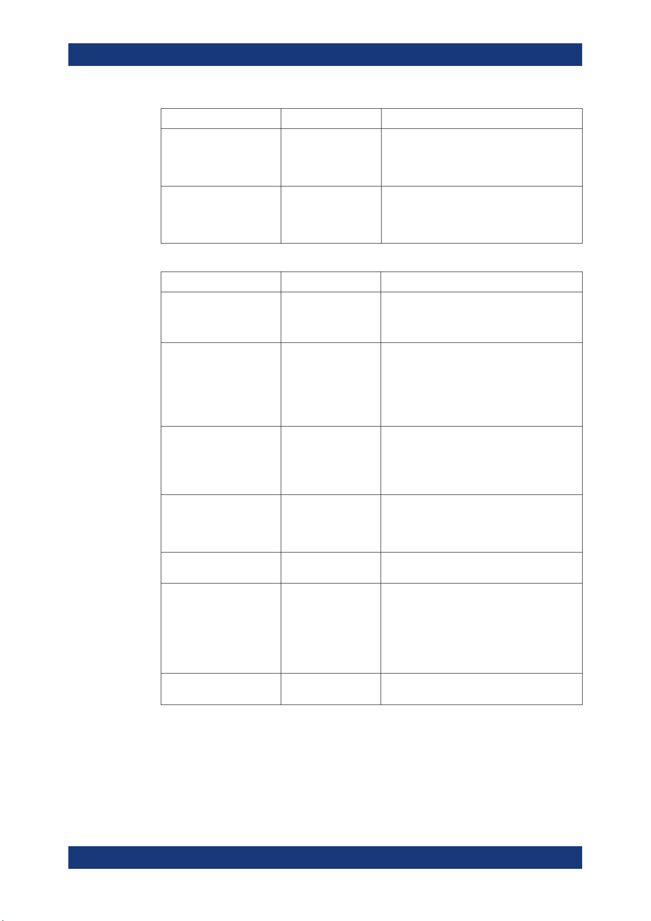
Table 6-4: Trigger-out signals
Trigger-out parameters Trigger conditions Descriptions
Output channel Output On
Output Off
Gated
If a trigger is detected, respective channel output
of the instrument turns on or off.
Digital Output Fault CC, CV, CR, Protection
and Sink, Output Off
If respective channel operation modes, protection
event or sink mode is detected, a trigger signal is
sent out at pin 11 of the Digital I/O connector.
If "Output Off" is selected, the "fault output" will be
active if the output of the selected channel is off.
See Figure 6-19.
Digital Output Out1 Trigger-in signal
Output On Ch1
If detected, a constant level trigger signal is sent
out at pin 4 of the Digital I/O connector.
If the pulse option is selected for the signal type,
an output pulse of 100 ms trigger signal is sent
out instead.
Digital Output Out2 Trigger-in signal
Output On Ch2
If detected, a constant level trigger signal is sent
out at pin 12 of the Digital I/O connector.
If the pulse option is selected, an output pulse of
100 ms trigger signal is sent out instead.
Logging Trigger-in signal If detected, the data logger starts recording the
instrument.
Arb Start triggered
Stop triggered
If a trigger is detected, respective channel starts
generating a complete arbitrary signal or steps
through the arbitrary signal for every trigger signal
detected.
The step time from the arbitrary signal is ignored
in the case when trigger condition is set as "Stop
triggered".
FastLog Trigger-in signal If detected, the FastLog module is enabled and
starts acquiring measurement data.
Trigger / Digital I/O
Loading ...
Loading ...
Loading ...