Loading ...
Loading ...
Loading ...
72
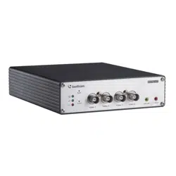
Output Setting
Figure 4-19
Select Enable to enable the output device. Choose the output signal that mostly suits the
device you are using: N/O (Open Circuit), N/C (Grounded Circuit), N/O Toggle, N/C Toggle,
N/O Pulse or N/C Pulse. For Toggle output type, the output will keep going on once it is
triggered until the next trigger. For Pulse output type, the output is triggered for the
amount of time you specify in the Trigger Pulse Mode for x Seconds field.
Alarm Settings:
You can choose to automatically activate the configured output device for alarm under
these conditions: video lost, tampering alarm, video recording start (Start Record), video
recording stop (Stop Record), disk write error (Rec Error) and hard disk full (HD Full).
Note the video recording start / stop function is only supported by GV-VS04H / 11 / 12 / 14.
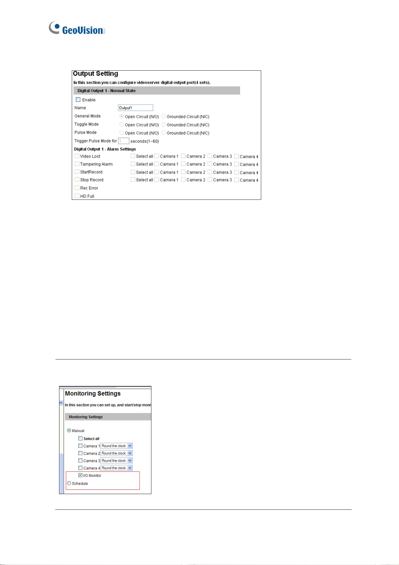
Important: The input/output settings only function after you start I/O Monitor manually
or by schedule. To configure the I/O monitoring, see 4.4 Monitoring.
Figure 4-20
Loading ...
Loading ...
Loading ...