Loading ...
Loading ...
Loading ...
Auxiliary Device Connectors
161
9
GV-VS2820 / 2800 / 21600
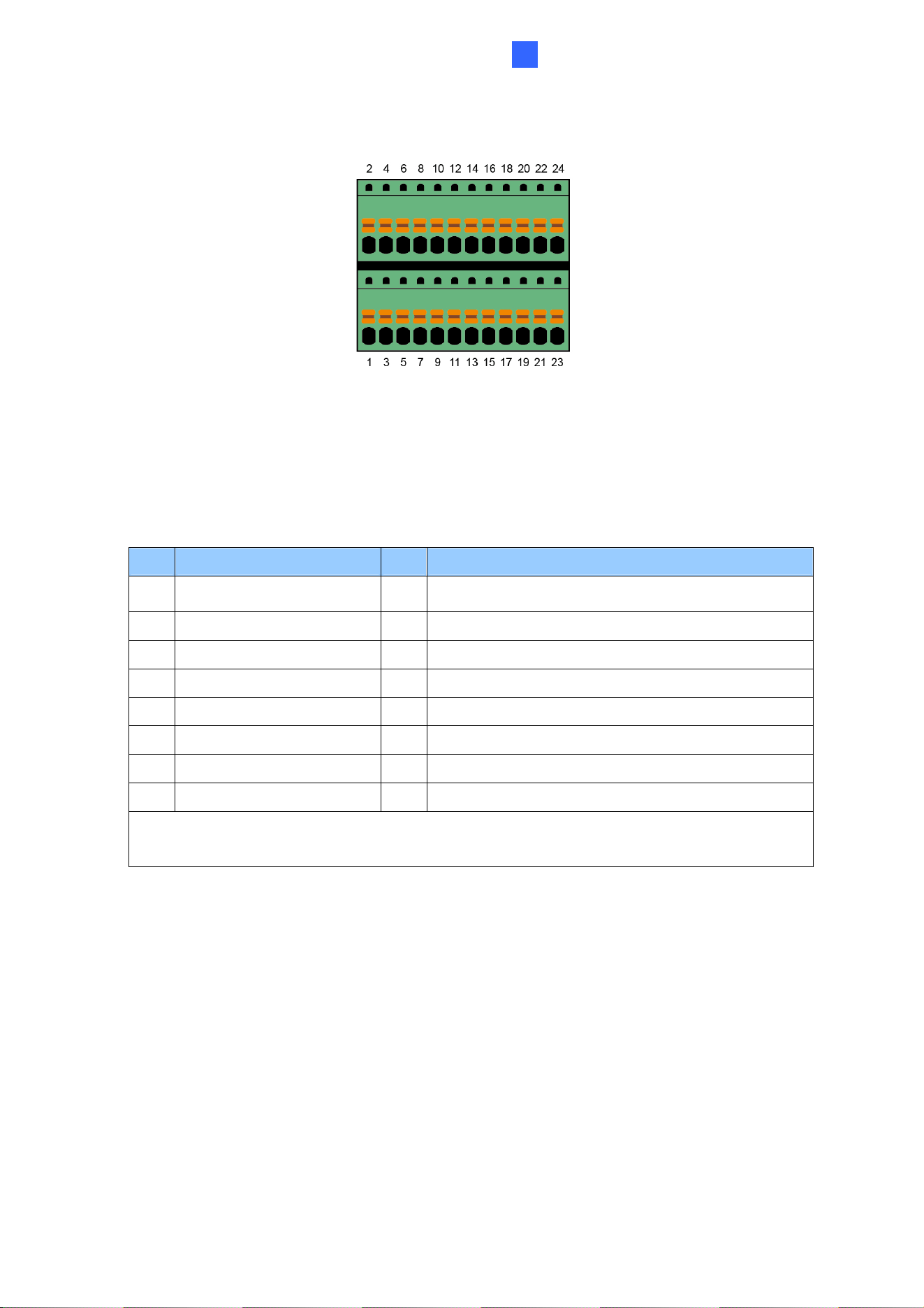
Figure 9-2
9.1.1 Pin Assignment
The table below lists the pin assignment for the terminal block.
GV-VS04H / 14
Pin Function Pin Function
1 Relay Output 1 9 DC 5V Out for GV-Relay Module, or GPS Module
2 Digital Input 1 10 Ground, or GPS Ground
3 Relay Output 2 11 RS 485+
4 Digital Input 2 12 Wiegand D0, or GPS RX
5 Relay Output 3 13 RS 485-
6 Digital Input 3 14 Wiegand D1, or GPS TX
7 Relay Output 4 15 Ground
8 Digital Input 4 16 DC 12V Out for Wiegand Card Reader
Note: To connect the GPS module, use Pin 9 for power supply, Pin 10 for ground, Pin 12
for GPS RX and Pin 14 for GPS TX.
Loading ...
Loading ...
Loading ...