Loading ...
Loading ...
Loading ...
I nt rodu ct ion
1
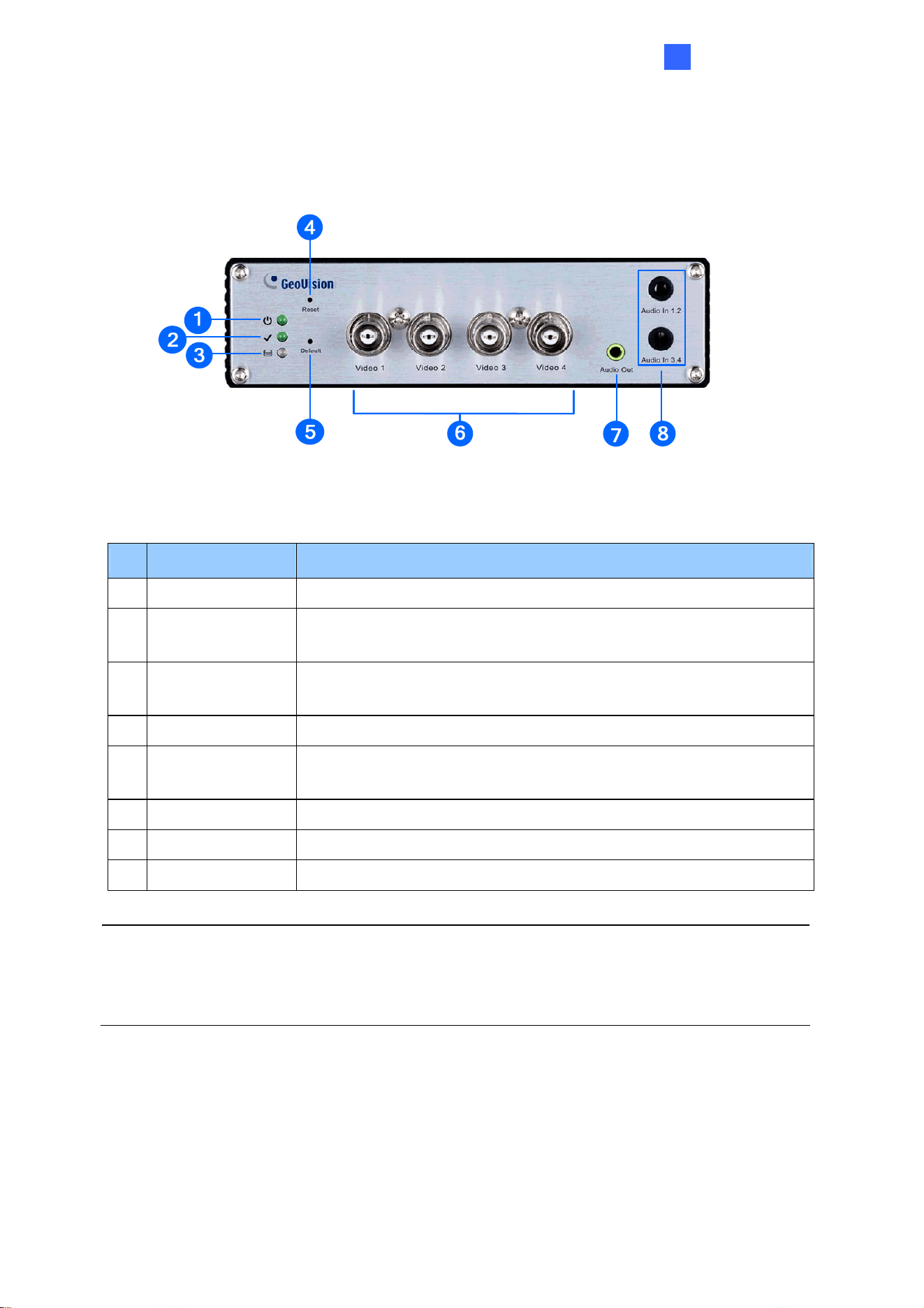
1.7.1.5 GV-VS2401
Figure 1-5
No. Name Function
1
Power LED This LED is on, indicating the power is supplied.
2 Ready LED
This LED is on, indicating the GV-Video Server is ready for
connection.
3
Disk Full/Fault
LED
This LED is on, indicating the hard drive is full or faulty.
4
Reset It reboots the GV-Video Server and keeps all current configurations.
5 Default Button
It resets all configurations to their factory settings. See 6.4
Restoring to Factory Default Settings.
6
Video Input 4 plugs for video inputs.
7
Audio Out A plug for the speaker device.
8
Audio In Each plug is for 2 audio inputs.
Note: W
hen transmitting video signals over a long distance, it is highly recommended to use
5C-FB coaxial cables or above to minimize the degradation of image quality. The
transmission distance should be within 300 m (984 ft).
17
Loading ...
Loading ...
Loading ...