Loading ...
Loading ...
Loading ...
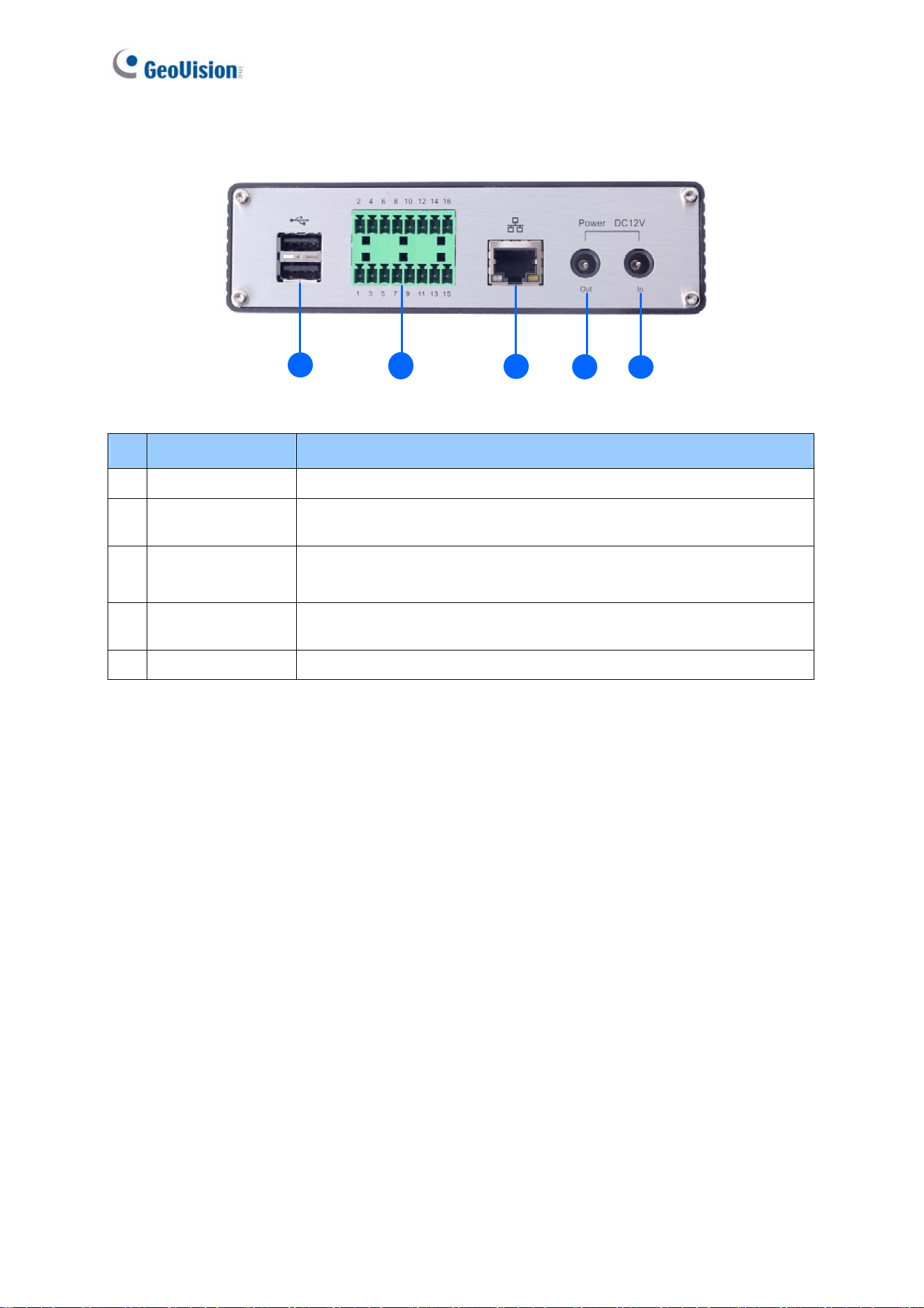
1.7.2.4 GV-VS2420 / 2400
4
1 2
3
5
Figure 1-11
No. Name Function
1 USB Port 2 USB ports for installing portable storage devices.
2 Terminal Block
The connectors for digital inputs, digital outputs, and PTZ cameras.
See Chapter 9 Auxiliary Device Connectors.
3
Gigabit Ethernet
Port
A plug for a 10/100/1000 Base-T Ethernet
4 Power Out
A plug to power the camera, by using the optional DC
Male-to-Male Cable, directly through the GV-Video Server
5 Power In A plug for power input.
22
Loading ...
Loading ...
Loading ...