Loading ...
Loading ...
Loading ...
81
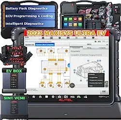
Figure 5-10 Breakout Lead Connection Diagram
NOTE
The required adapter or breakout leads may vary by vehicles. Please make
the correct connection according to your actual situation.
10. Power up the EVDiag Box. Ensure the EVDiag Box is connected to the DC
power supply. Tap OK on the tablet’s Connection Diagram screen to confirm
the connection. The Main Screen will appear once the link has been
established.
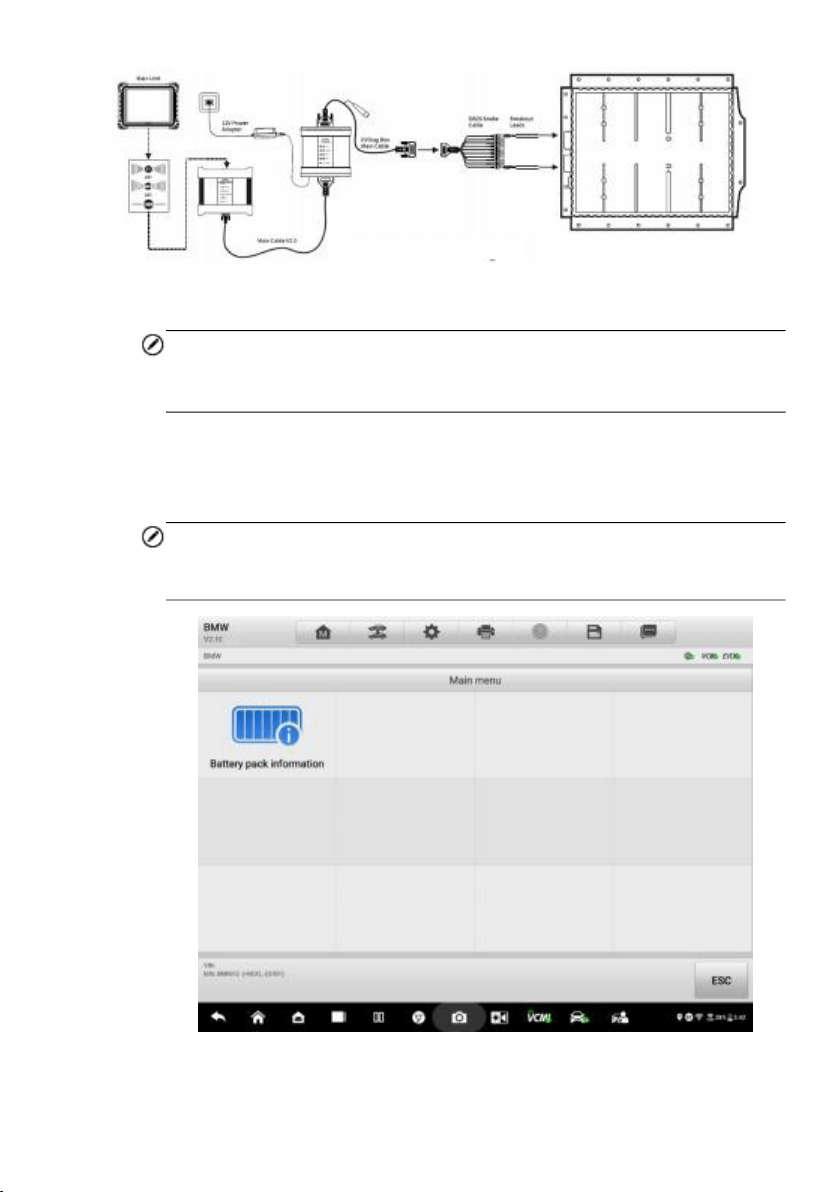
NOTE
After the EVDiag Box is powered up, a green check will appear at the bottom-
right corner of the EVDB icon.
Figure 5-11 Main Menu on Vehicle Mode
Loading ...
Loading ...
Loading ...