Loading ...
Loading ...
Loading ...
234
General Introduction
Component Locations
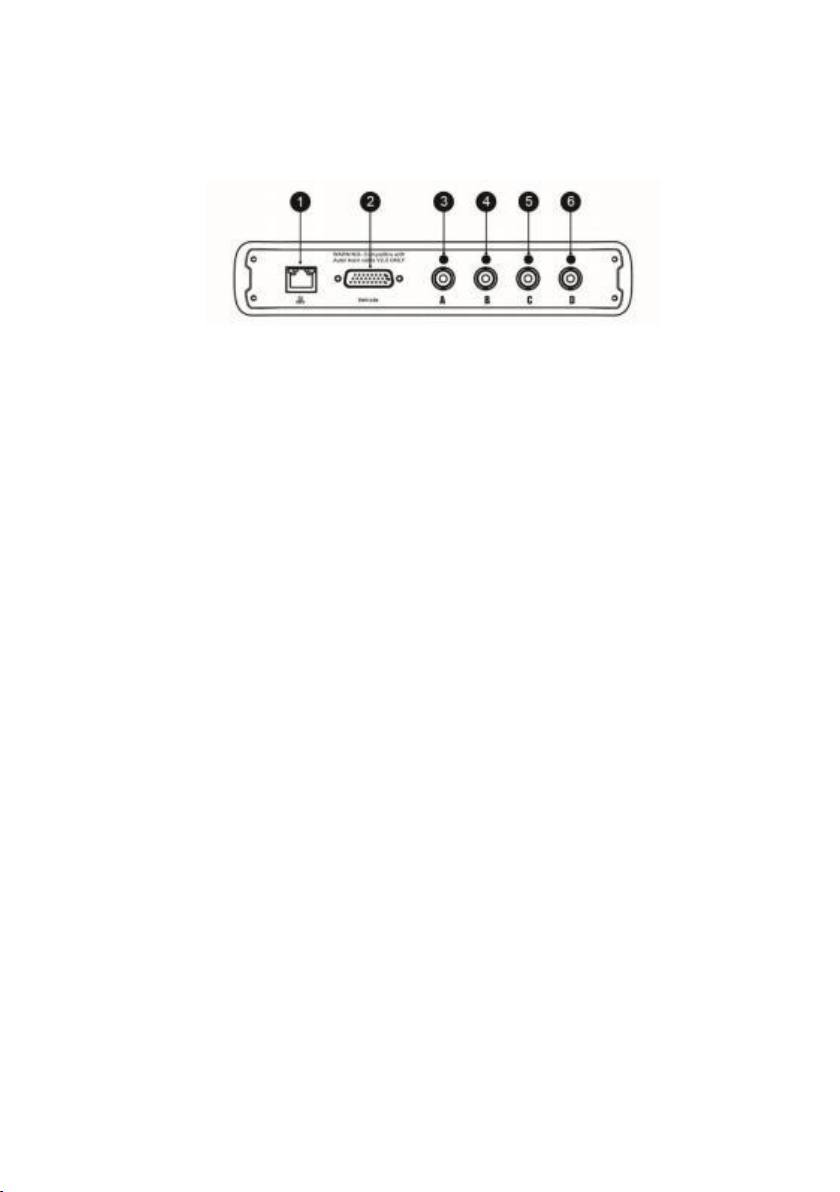
The main connectors are located at the bottom of the VCMI device.
Figure 9-117 VCMI Top View
1. Ethernet Connector
2. Vehicle Data Connector
3. Input Channel A
4. Input Channel B
5. Input Channel C
6. Input Channel D
Getting Started
Before opening the OBDII CAN Bus Check application, you have to complete three steps
below:
1 ) Connect the VCMI device to the tablet via Wi- Fi, BT or the supplied USB, see
Establish Vehicle Communication.
2) Connect the VCMI device to the vehicle's OBDII connector.
3) Place the ignition in the key on position .
Loading ...
Loading ...
Loading ...