Home
Bookmarks
Home
Autel
Autel MAXISYS ULTRA EV SCANNER User Manual
Page 69
Autel MAXISYS ULTRA EV SCANNER MaxiSys Ultra EV: 2023 UltraEV Intelligent Scanner High-Voltage System & Battery Pack Analysis
User Manual - Page 69
For MAXISYS ULTRA EV SCANNER.
PDF File Manual
,
324 pages
,
Read Online
|
Download pdf file
Trademarks
Copyright Information
Disclaimer of Warranties and Limitation of Liabili
For Services and Support:
Safety Messages
Safety Instructions
Safety Warnings
1 Using This Manual
Conventions
Bold Text
Notes and Important Messages
Notes
Important
Hyperlink
Illustrations
Procedures
2 General Introduction
MaxiSys Tablet
Function Description
Power Sources
Internal Battery Pack
AC/DC Power Supply â using AC/DC adapter or dockin
Vehicle Power
Technical Specifications
MaxiFlash VCMI â Vehicle Communication and
Function Description
Communication Capability
Measurement Capability
Programming Capability
Power Sources
Vehicle Power
AC/DC Power Supply
Built-in Battery Pack
Technical Specifications
EVDiag Box
Function Description
Power Source
Technical Specifications
Accessories Kit
Main Cable V2.0
Battery Pack Accessories
OBDI-Type Adapters (optional)
Other Accessories
3 Getting Started
Power Up
Application Buttons
Locator and Navigation Buttons
System Status Icons
Power Down
Reboot System
4 New Energy
Establish Vehicle Communication
Vehicle Connection
VCMI Connection
No Communication Message
Getting Started
New Energy Vehicle Menu Layout
Vehicle Identification
Auto Detect
Manual Input
Scan VIN/License
Manual Vehicle Selection
Navigation
New Energy Screen Layout
New Energy Toolbar
Current Directory Path
Status Information Bar
Navigation Bar
Main Section
Function Buttons
Screen Messages
Making Selections
Auto Scan
Auto Scan Results
Control Unit
ECU Information
Trouble Codes
Read Codes
Erase Codes
Live Data
Active Test
HV System Diagnostics
System List >SME (Storage Management Electronics)
System Block Diagram
Special Function
Coding
Reprogramming
Re-flash Errors
Diagnostic Report
Pre-Scan and Post-Scan
Diagnostic Report
Diagnostic Report Cloud Sharing
Exit New Energy application
5 Battery Pack Test
Getting Started
Battery Pack Information
6 Diagnostics
Generic OBDII Operations
General Procedure
Function Descriptions
DTC & FFD
I/M Readiness
Live Data
O2 Sensor Monitor
On-Board Monitor
Component Test
Vehicle Information
Vehicle Status
7 Intelligent Diagnostics
Accessing Intelligent Diagnostics Function
Auto Scan
Scan System Faults
Access via Intelligent Diagnostics Button
Access via Intelligent Diagnostics Icon
Intelligent Diagnostics Operations
Vehicle System and Detected DTC(s)
Technical Service Bulletin (OEM Information)
DTC Analysis
Repair Assist
Repair Tips
Component Measurement
8 Service
Oil Reset Service
Electric Parking Brake (EPB) Service
EPB Safety
Tire Pressure Monitoring System (TPMS) Service
Diesel Particle Filter (DPF) Service
Immobilizer (IMMO) Service
9 Measurement
Oscilloscope
Safety Information
General Introduction
Component Locations
Technical Specifications
Accessories
Getting Started
Oscilloscope Update
APK Update
Firmware Update
Screen Layout and Operations
Upper Toolbar
Scope Icon
Start/Stop Button
Presets Menu
Waveform Library
Online Waveform Library
Local Waveform Library
Settings Menu
Mode
Window Function
Waveform Generator
Decoding Settings
Startup Setting
Math Channel
File Menu
Help Menu
Number of Samples
Auto Scale
Main View Section
Measurement Overrange Indicator
Channel Selection
Waveform Zooming
Measurement Rulers
Zero Baseline
Parameter and Help
Real-time Help
Lower Toolbar
Channel Control
Channel Color
Amplitude Setting
Probe Setting
Probe Edit
LPF (Low-pass Filtering)
Trigger
Edge Triggering
Advanced Edge
Window
Pulse Width
Interval
Window Pulse Width
Horizontal Distortion
Window Distortion
Underthrow
Buffer
Time Base
Measurement
Troubleshooting
Glossary
AC/DC Control
Aliasing
Amplitude
Analog Bandwidth
Buffer Size/Cache Size
Frequency
Peak to peak voltage
Time Base
Voltage Range
Sampling Rate
Safety Information
General Introduction
Component Locations
Technical Specifications
Accessories
Getting Started
Multimeter Update
APK Update
Screen Layout and Operations
Upper Toolbar
Multimeter Icon
Start/Stop Button
Show Mode Menu
File Menu
Help Menu
Main View Section
Digital Mode
Waveform Mode
Channel Selection
Waveform Zooming
Measurement Rulers
Zero Baseline
Wiring Diagram and Help
Digital + Waveform Mode
Lower Toolbar
Measurement Setting
Amplitude Setting
Testing Procedures
Probe Edit
Buffer
Troubleshooting
Glossary
AC
DC
Amperage
Amplitude
Frequency
Duty Cycle
Peak to Peak
Diode
Grid
Safety Information
General Introduction
Component Locations
Technical Specifications
Accessories
Getting Started
Waveform Generator Update
APK Update
Screen Layout and Operations
Upper Toolbar
Waveform Generator Icon
Start/Stop Button
File Menu
Help Menu
Main View Section
Channel Selection
Waveform Zooming
Measurement Ruler
Zero Baseline
Wiring Diagram and Help
Lower Toolbar
Signal Mode Setting
DC Voltage
Actuator Drive
Square Wave
Square Wave (X+Y)
Triangle Waveform
Arbitrary Waveform
Voltage Setting
Frequency Setting
Duty Cycle Setting
Troubleshooting
Glossary
Safety Information
General Introduction
Component Locations
Getting Started
Bus Inspection
APK Update
Screen Layout and Operations
Upper Toolbar
OBD Icon
Start/Stop Button
Settings Menu
File Menu
Help Menu
Main View Section and Lower Toolbar
Indicator Mode
Main View Section
Lower Toolbar
Test Procedure
Waveform Mode
Main View Section
Lower Toolbar
Troubleshooting
Glossary
Vehicle Bus
CAN Bus
SAE International
SAE J1708
SAE J1939
J1850
OBD
OBD-II diagnostic connector
DLC
10 Data Manager
Vehicle History
Historical Test Record
Workshop Information
Customer
Image
Report
PDF Files
Review Data
Data Logging
Uninstall Apps
11 Settings
Operations
Unit
Language
Printing Settings
Printing Setting
Printing Operations
Report Settings
Push Notifications
Auto Update
ADAS Settings
Vehicle List
EVDiag Box Settings
Country/ Region Code
System Settings
About
12 Update
13 VCMI Manager
Wi-Fi Connection
BT Pairing
Update
14 ADAS
15 Support
Product Registration
Support Screen Layout
My Account
Personal Info
Update Info
Service Info
Training
Data Logging
FAQ Database
16
Operations
17 Quick Link
18 MaxiViewer
19 MaxiVideo
20
Test Preparation
Inspect the Battery
Connect the Battery Tester
Battery Test
Starter Test
Generator Test
Out-vehicle Test
Test Procedure
21 OEM Authorization
22 User Feedback
23 Maintenance and Service
Maintenance Instructions
Troubleshooting Checklist
About Battery Usage
Service Procedures
Technical Support
Repair Service
Other Services
24 Compliance Information
25 Warranty
12-month Limited Warranty
This warranty does not apply to:
Page 69/324
Page 1
Page 2
Page 3
Page 4
Page 5
Page 6
Page 7
Page 8
Page 9
Page 10
Page 11
Page 12
Page 13
Page 14
Page 15
Page 16
Page 17
Page 18
Page 19
Page 20
Page 21
Page 22
Page 23
Page 24
Page 25
Page 26
Page 27
Page 28
Page 29
Page 30
Page 31
Page 32
Page 33
Page 34
Page 35
Page 36
Page 37
Page 38
Page 39
Page 40
Page 41
Page 42
Page 43
Page 44
Page 45
Page 46
Page 47
Page 48
Page 49
Page 50
Page 51
Page 52
Page 53
Page 54
Page 55
Page 56
Page 57
Page 58
Page 59
Page 60
Page 61
Page 62
Page 63
Page 64
Page 65
Page 66
Page 67
Page 68
Page 69
Page 70
Page 71
Page 72
Page 73
Page 74
Page 75
Page 76
Page 77
Page 78
Page 79
Page 80
Page 81
Page 82
Page 83
Page 84
Page 85
Page 86
Page 87
Page 88
Page 89
Page 90
Page 91
Page 92
Page 93
Page 94
Page 95
Page 96
Page 97
Page 98
Page 99
Page 100
Page 101
Page 102
Page 103
Page 104
Page 105
Page 106
Page 107
Page 108
Page 109
Page 110
Page 111
Page 112
Page 113
Page 114
Page 115
Page 116
Page 117
Page 118
Page 119
Page 120
Page 121
Page 122
Page 123
Page 124
Page 125
Page 126
Page 127
Page 128
Page 129
Page 130
Page 131
Page 132
Page 133
Page 134
Page 135
Page 136
Page 137
Page 138
Page 139
Page 140
Page 141
Page 142
Page 143
Page 144
Page 145
Page 146
Page 147
Page 148
Page 149
Page 150
Page 151
Page 152
Page 153
Page 154
Page 155
Page 156
Page 157
Page 158
Page 159
Page 160
Page 161
Page 162
Page 163
Page 164
Page 165
Page 166
Page 167
Page 168
Page 169
Page 170
Page 171
Page 172
Page 173
Page 174
Page 175
Page 176
Page 177
Page 178
Page 179
Page 180
Page 181
Page 182
Page 183
Page 184
Page 185
Page 186
Page 187
Page 188
Page 189
Page 190
Page 191
Page 192
Page 193
Page 194
Page 195
Page 196
Page 197
Page 198
Page 199
Page 200
Page 201
Page 202
Page 203
Page 204
Page 205
Page 206
Page 207
Page 208
Page 209
Page 210
Page 211
Page 212
Page 213
Page 214
Page 215
Page 216
Page 217
Page 218
Page 219
Page 220
Page 221
Page 222
Page 223
Page 224
Page 225
Page 226
Page 227
Page 228
Page 229
Page 230
Page 231
Page 232
Page 233
Page 234
Page 235
Page 236
Page 237
Page 238
Page 239
Page 240
Page 241
Page 242
Page 243
Page 244
Page 245
Page 246
Page 247
Page 248
Page 249
Page 250
Page 251
Page 252
Page 253
Page 254
Page 255
Page 256
Page 257
Page 258
Page 259
Page 260
Page 261
Page 262
Page 263
Page 264
Page 265
Page 266
Page 267
Page 268
Page 269
Page 270
Page 271
Page 272
Page 273
Page 274
Page 275
Page 276
Page 277
Page 278
Page 279
Page 280
Page 281
Page 282
Page 283
Page 284
Page 285
Page 286
Page 287
Page 288
Page 289
Page 290
Page 291
Page 292
Page 293
Page 294
Page 295
Page 296
Page 297
Page 298
Page 299
Page 300
Page 301
Page 302
Page 303
Page 304
Page 305
Page 306
Page 307
Page 308
Page 309
Page 310
Page 311
Page 312
Page 313
Page 314
Page 315
Page 316
Page 317
Page 318
Page 319
Page 320
Page 321
Page 322
Page 323
Page 324
Contents
Table of Contents
Search
Previous
Next
Troubleshooting
Bookmarks
Loading ...
Loading ...
Loading ...
60
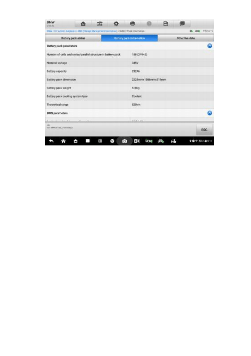
Figure
4-28
Battery
Pack
Information
Screen
C.
Other
L
ive
Data
The
re
are
data
list
di
spla
ye
d
on
this
scre
en,
including
parame
ter
names,
values
and
units
.
Swipe
th
e
screen
up
or
d
own
to
quickly
browse
t
he
dat
a
list.
See
Live
Data
for
mo
re
details.
Loading ...
Loading ...
Loading ...
File type: PDF
File name: 70633913_maxisys-ultra-ev-scanner.pdf
File size: 4.7 MB
File Language: English
Pages: 324
Author: Autel
File created: 2023-02-21
Published:
2023-06-23
Updated: 2023-06-22
Download File
Table of Contents
×
Trademarks
1
Copyright Information
1
Disclaimer of Warranties and Limitation of Liabili
1
For Services and Support:
1
Safety Messages
2
Safety Instructions
2
Safety Warnings
3
1 Using This Manual
10
Conventions
10
Bold Text
10
Notes and Important Messages
10
Notes
10
Important
10
Hyperlink
11
Illustrations
11
Procedures
11
2 General Introduction
12
MaxiSys Tablet
12
Function Description
12
Power Sources
14
Internal Battery Pack
15
AC/DC Power Supply â using AC/DC adapter or dockin
15
Vehicle Power
15
Technical Specifications
15
MaxiFlash VCMI â Vehicle Communication and
17
Function Description
17
Communication Capability
19
Measurement Capability
19
Programming Capability
19
Power Sources
20
Vehicle Power
20
AC/DC Power Supply
20
Built-in Battery Pack
20
Technical Specifications
20
EVDiag Box
21
Function Description
21
Power Source
22
Technical Specifications
22
Accessories Kit
22
Main Cable V2.0
22
Battery Pack Accessories
23
OBDI-Type Adapters (optional)
24
Other Accessories
25
3 Getting Started
26
Power Up
26
Application Buttons
27
Locator and Navigation Buttons
28
System Status Icons
30
Power Down
30
Reboot System
30
4 New Energy
31
Establish Vehicle Communication
31
Vehicle Connection
31
VCMI Connection
33
No Communication Message
35
Getting Started
35
New Energy Vehicle Menu Layout
36
Vehicle Identification
38
Auto Detect
38
Manual Input
40
Scan VIN/License
41
Manual Vehicle Selection
42
Navigation
43
New Energy Screen Layout
43
New Energy Toolbar
45
Current Directory Path
46
Status Information Bar
46
Navigation Bar
46
Main Section
47
Function Buttons
47
Screen Messages
48
Making Selections
48
Auto Scan
48
Auto Scan Results
49
Control Unit
51
ECU Information
52
Trouble Codes
53
Read Codes
53
Erase Codes
55
Live Data
55
Active Test
62
HV System Diagnostics
63
System List >SME (Storage Management Electronics)
65
System Block Diagram
70
Special Function
74
Coding
76
Reprogramming
76
Re-flash Errors
77
Diagnostic Report
77
Pre-Scan and Post-Scan
77
Diagnostic Report
78
Diagnostic Report Cloud Sharing
81
Exit New Energy application
82
5 Battery Pack Test
84
Getting Started
84
Battery Pack Information
91
6 Diagnostics
92
Generic OBDII Operations
92
General Procedure
93
Function Descriptions
94
DTC & FFD
94
I/M Readiness
95
Live Data
96
O2 Sensor Monitor
96
On-Board Monitor
96
Component Test
96
Vehicle Information
96
Vehicle Status
96
7 Intelligent Diagnostics
97
Accessing Intelligent Diagnostics Function
97
Auto Scan
97
Scan System Faults
98
Access via Intelligent Diagnostics Button
100
Access via Intelligent Diagnostics Icon
100
Intelligent Diagnostics Operations
103
Vehicle System and Detected DTC(s)
104
Technical Service Bulletin (OEM Information)
105
DTC Analysis
106
Repair Assist
106
Repair Tips
109
Component Measurement
110
8 Service
111
Oil Reset Service
111
Electric Parking Brake (EPB) Service
112
EPB Safety
112
Tire Pressure Monitoring System (TPMS) Service
112
Diesel Particle Filter (DPF) Service
113
Immobilizer (IMMO) Service
114
9 Measurement
116
Oscilloscope
116
Safety Information
116
General Introduction
118
Component Locations
118
Technical Specifications
119
Accessories
120
Getting Started
123
Oscilloscope Update
124
APK Update
124
Firmware Update
125
Screen Layout and Operations
126
Upper Toolbar
127
Scope Icon
128
Start/Stop Button
128
Presets Menu
129
Waveform Library
133
Online Waveform Library
133
Local Waveform Library
136
Settings Menu
136
Mode
137
Window Function
141
Waveform Generator
145
Decoding Settings
146
Startup Setting
149
Math Channel
150
File Menu
152
Help Menu
153
Number of Samples
154
Auto Scale
154
Main View Section
154
Measurement Overrange Indicator
154
Channel Selection
155
Waveform Zooming
156
Measurement Rulers
157
Zero Baseline
159
Parameter and Help
160
Real-time Help
161
Lower Toolbar
162
Channel Control
163
Channel Color
164
Amplitude Setting
164
Probe Setting
167
Probe Edit
168
LPF (Low-pass Filtering)
170
Trigger
172
Edge Triggering
173
Advanced Edge
175
Window
176
Pulse Width
177
Interval
178
Window Pulse Width
178
Horizontal Distortion
178
Window Distortion
178
Underthrow
178
Buffer
178
Time Base
179
Measurement
180
Troubleshooting
186
Glossary
187
AC/DC Control
187
Aliasing
187
Amplitude
187
Analog Bandwidth
187
Buffer Size/Cache Size
187
Frequency
187
Peak to peak voltage
187
Time Base
187
Voltage Range
188
Sampling Rate
188
Safety Information
189
General Introduction
190
Component Locations
190
Technical Specifications
191
Accessories
192
Getting Started
193
Multimeter Update
193
APK Update
194
Screen Layout and Operations
194
Upper Toolbar
195
Multimeter Icon
196
Start/Stop Button
196
Show Mode Menu
196
File Menu
197
Help Menu
199
Main View Section
199
Digital Mode
200
Waveform Mode
200
Channel Selection
201
Waveform Zooming
201
Measurement Rulers
202
Zero Baseline
203
Wiring Diagram and Help
203
Digital + Waveform Mode
205
Lower Toolbar
205
Measurement Setting
206
Amplitude Setting
207
Testing Procedures
209
Probe Edit
210
Buffer
212
Troubleshooting
212
Glossary
213
AC
213
DC
213
Amperage
213
Amplitude
213
Frequency
213
Duty Cycle
213
Peak to Peak
213
Diode
213
Grid
213
Safety Information
214
General Introduction
215
Component Locations
215
Technical Specifications
216
Accessories
216
Getting Started
217
Waveform Generator Update
218
APK Update
219
Screen Layout and Operations
220
Upper Toolbar
221
Waveform Generator Icon
222
Start/Stop Button
222
File Menu
222
Help Menu
223
Main View Section
224
Channel Selection
224
Waveform Zooming
225
Measurement Ruler
225
Zero Baseline
226
Wiring Diagram and Help
226
Lower Toolbar
227
Signal Mode Setting
228
DC Voltage
228
Actuator Drive
229
Square Wave
230
Square Wave (X+Y)
230
Triangle Waveform
231
Arbitrary Waveform
232
Voltage Setting
232
Frequency Setting
235
Duty Cycle Setting
237
Troubleshooting
240
Glossary
240
Safety Information
242
General Introduction
243
Component Locations
243
Getting Started
243
Bus Inspection
244
APK Update
244
Screen Layout and Operations
246
Upper Toolbar
246
OBD Icon
247
Start/Stop Button
247
Settings Menu
247
File Menu
249
Help Menu
250
Main View Section and Lower Toolbar
251
Indicator Mode
251
Main View Section
252
Lower Toolbar
252
Test Procedure
254
Waveform Mode
255
Main View Section
255
Lower Toolbar
258
Troubleshooting
268
Glossary
268
Vehicle Bus
268
CAN Bus
268
SAE International
268
SAE J1708
268
SAE J1939
268
J1850
269
OBD
269
OBD-II diagnostic connector
269
DLC
269
10 Data Manager
270
Vehicle History
271
Historical Test Record
272
Workshop Information
273
Customer
274
Image
275
Report
277
PDF Files
278
Review Data
278
Data Logging
278
Uninstall Apps
278
11 Settings
279
Operations
279
Unit
279
Language
280
Printing Settings
280
Printing Setting
280
Printing Operations
280
Report Settings
281
Push Notifications
282
Auto Update
282
ADAS Settings
283
Vehicle List
283
EVDiag Box Settings
283
Country/ Region Code
284
System Settings
285
About
285
12 Update
286
13 VCMI Manager
288
Wi-Fi Connection
289
BT Pairing
290
Update
291
14 ADAS
293
15 Support
294
Product Registration
294
Support Screen Layout
295
My Account
296
Personal Info
296
Update Info
296
Service Info
297
Training
297
Data Logging
297
FAQ Database
298
16
299
Operations
299
17 Quick Link
301
18 MaxiViewer
302
19 MaxiVideo
304
20
305
Test Preparation
305
Inspect the Battery
305
Connect the Battery Tester
306
Battery Test
308
Starter Test
310
Generator Test
311
Out-vehicle Test
312
Test Procedure
312
21 OEM Authorization
315
22 User Feedback
316
23 Maintenance and Service
317
Maintenance Instructions
317
Troubleshooting Checklist
317
About Battery Usage
318
Service Procedures
319
Technical Support
319
Repair Service
320
Other Services
321
24 Compliance Information
322
25 Warranty
324
12-month Limited Warranty
324
This warranty does not apply to:
324
Search:
×
Search