
Loading ...
Loading ...
Loading ...
182
IMPORTANT
When using the multimeter function, please insert the supplied multimeter probes to
the multimeter probe jacks. When measuring the current, use a current clamp to
connect to the input channel A on the top of the VCMI device .
The multimeter LED is located on the front panel of the VCMI device. When the VCMI
is properly connected and powered on, the multimeter LED lights green when
operating in the multimeter mode.
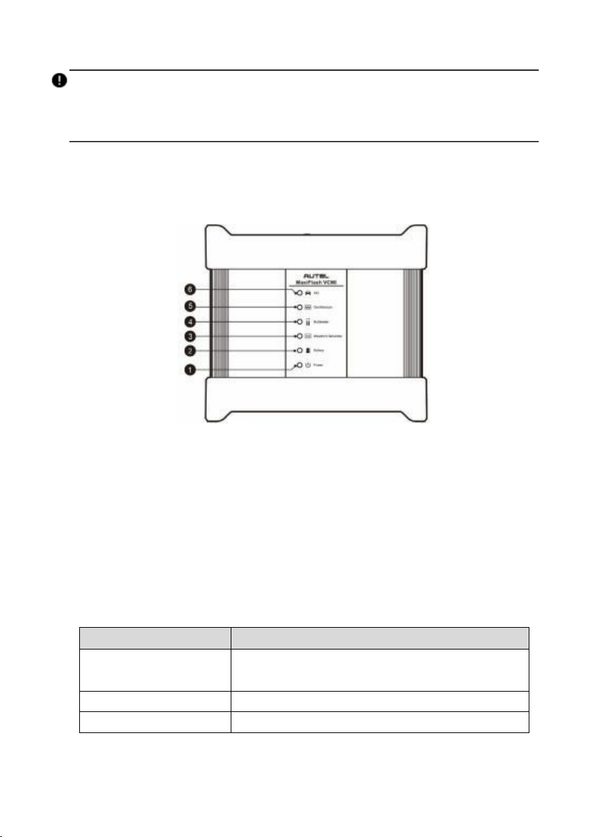
Figure 9-68 VCMI Front View
1. Power LED
2. Battery LED
3. Waveform Generator LED
4. Multimeter LED
5. Oscilloscope LED
6. Vehicle LED
Technical Specifications
Item
Description
Voltage Range
VDC 200 V
VAC 200 V RMS
Resistance Range
1 Q to 10 MQ
Diode
2 V
Loading ...
Loading ...
Loading ...