
Loading ...
Loading ...
Loading ...
155
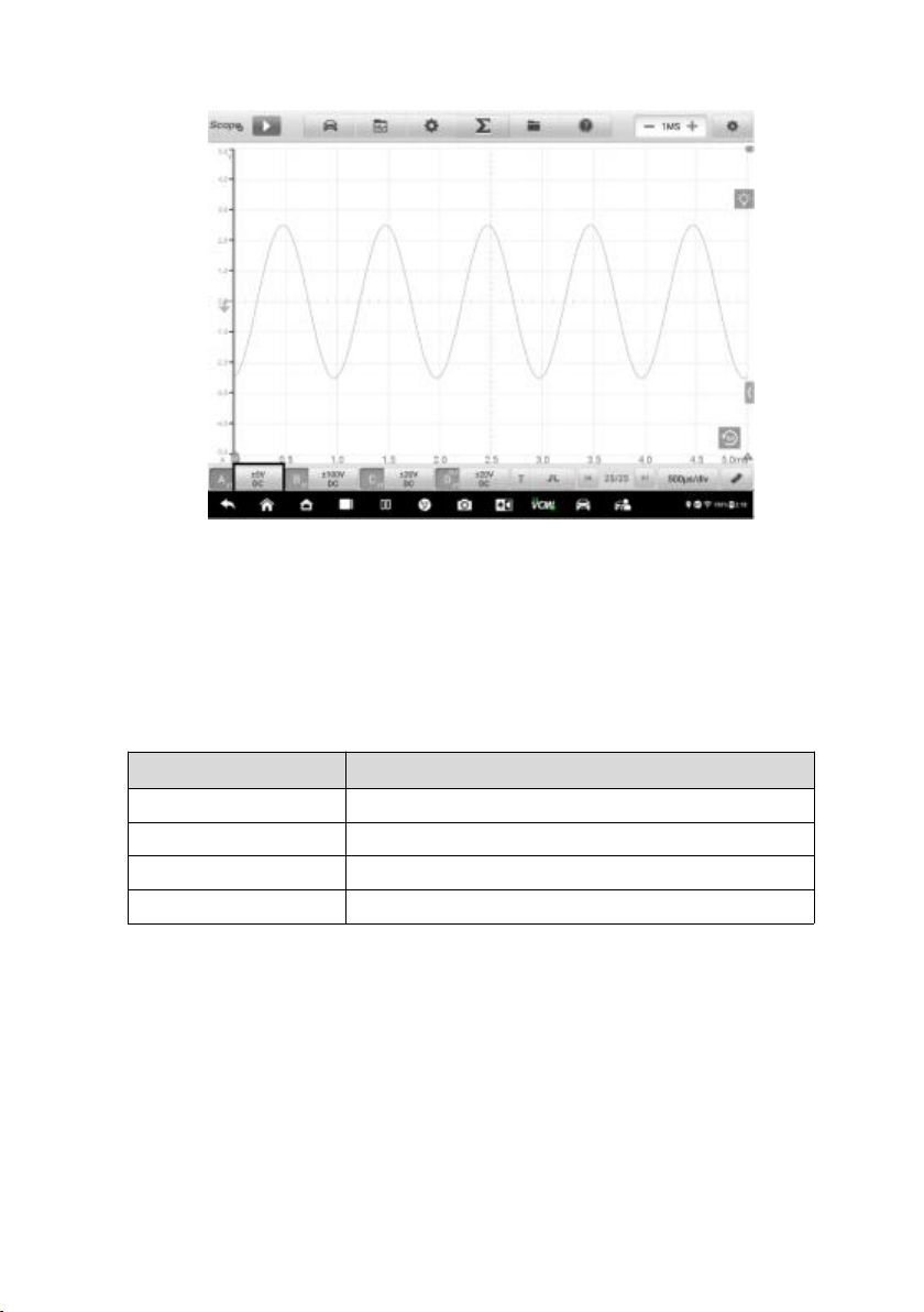
Figure 9-44 Activate Channel Screen
3. Tap the left column of channel control button again to close the channel.
The closed channel button displays gray.
Channel Color
Identify each channel waveform by color.
Table 9-6 Channel Color Table
Input Channel
Color
A
Red
B
Green
C
Blue
D
Yellow
Amplitude Setting
The amplitude, probe, and low-pass filtering settings can be configured in the
Channel control dialog box.
The amplitude setting allow you to set up the oscilloscope to capture signals with the
specified range. If the input signal exceeds the selected range, an over-range
Loading ...
Loading ...
Loading ...