Loading ...
Loading ...
Loading ...
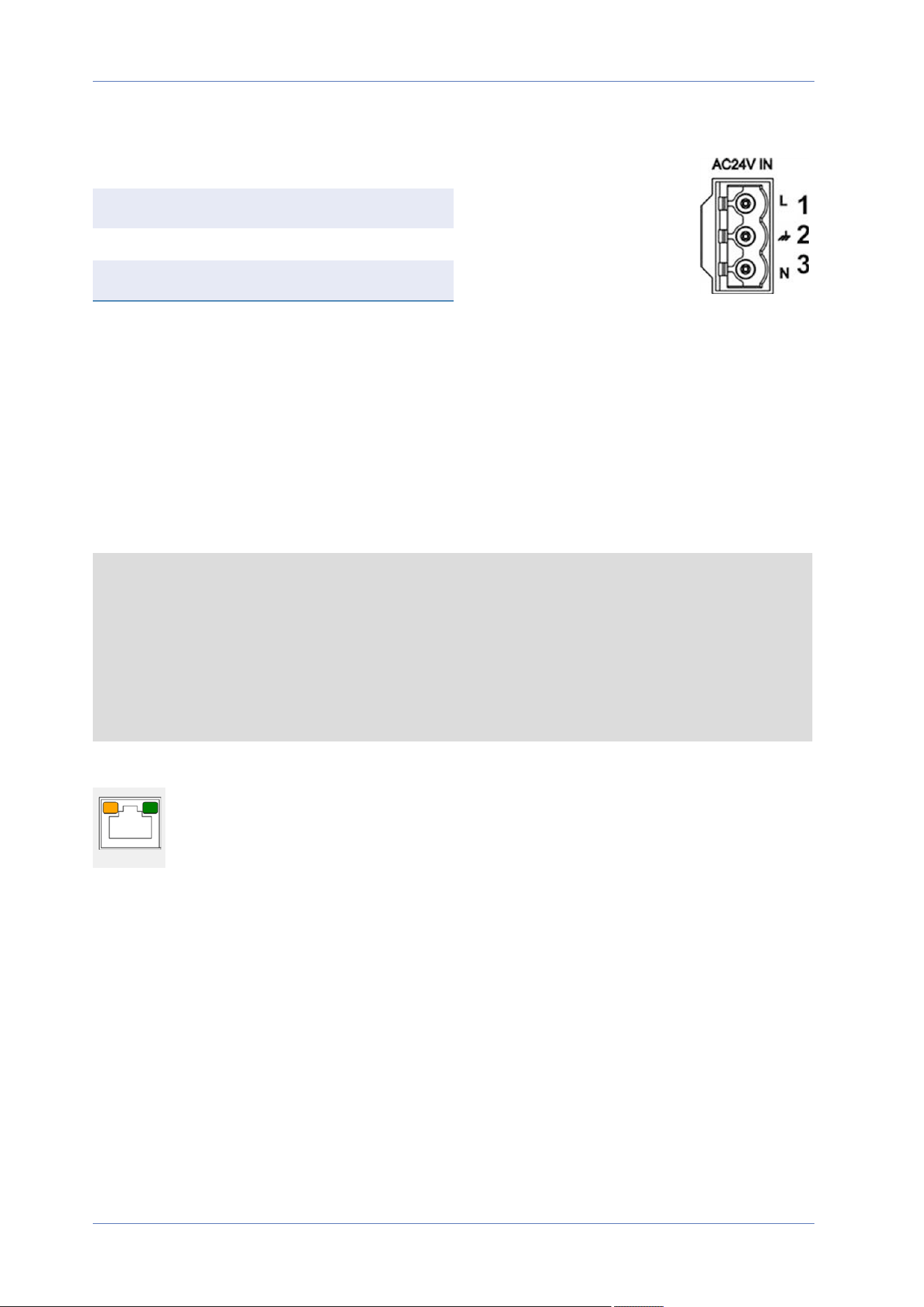
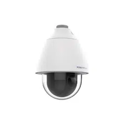
Diagram and Pin Definition for AC24V Power Connection
Pin Definition
1 AC24V L
2 GND
3 AC24V N
Connecting Ethernet Cable
Ethernet Cable Connection
Connect one end of the Ethernet cable to the RJ-45 connector of the camera and plug the other end
of the cable into the network switch or PC.
NOTE!
n
The length of the Ethernet cable should not exceed 100m/300ft.
n
Check the status of the link indicator and the activity indicator LEDs of the switch. If the
LEDs are unlit, please check the LAN connection.
n
In some cases, an Ethernet crossover cable may be needed when connecting the camera
directly to the PC.
Ethernet Connector LEDs
n
Green Link LED indicates good network connection.
n
Orange Activity LED flashes for network activity indication.
Connection
Connecting Ethernet Cable
19 / 130
Loading ...
Loading ...
Loading ...