User Guide
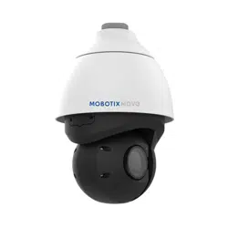
MOBOTIX 2MP Low-Light Video Analytics Speed Dome
©2023MOBOTIX AG
V1.06_9/28/2023, Order Code:Mx-SD2A-230-LL-VA

Table of Contents
Table of Contents
Table of Contents 2
Before You Start 5
Support 6
MOBOTIX Support 6
MOBOTIX eCampus 6
MOBOTIX Community 6
Safety Notes 7
Legal Notes 7
Overview 9
Features 10
Package Contents 10
Dimensions 11
Accessories 12
Further Reading 14
Connection 15
Camera Cabling 16
Camera Connectors 17
microSD Card Slot 18
Reset Button 18
Connecting Power 18
Connecting Ethernet Cable 19
Connecting Audio/Alarm I/O & RS485 20
Installation 21
General Remarks 22
Camera Installation 22
Camera Installation Notice 22
Installing to a Wall 23
Installing to a Ceiling 23
Configuration 25
System Requirements for Operating the Camera 26
Accessing the Camera 26
Setting the Video Resolution 28
Default Resolution 28
2 / 130

Exporting/Importing Configuration Files 29
Menu Reference 31
The Camera Menu 34
The “Home” Tab 35
Function Items on Home Page 35
The “System” Tab 40
System 40
Security 42
Network 49
DDNS 57
Mail 58
FTP 58
HTTP 58
MxMessageSystem 59
Events (Alarm Settings) 60
Storage Management 77
Recording 80
Schedule 82
File Location (Snapshots and Web Recording) 83
View Information 83
Factory Default 84
Software Version 85
Software Upgrade 85
Maintenance 85
The “Streaming” Tab 87
Video Configuration 88
Video Rotation 90
Video Text Overlay 91
Video OCX Protocol 92
Audio (Audio Mode and Bit Rate Settings) 92
The “Camera” Tab 95
Exposure 95
White Balance 97
Picture Adjustment 101
Color Style 102
IR Function 102
Noise Reduction 104
HDR Type 104
Table of Contents
3 / 130

Table of Contents
Gamma HDR 105
Image Stabilizer 105
Digital Zoom 106
Defog 106
Profile 106
TV System 107
The “PTZ” Tab 108
Preset 108
Cruise 109
Auto Pan 109
Sequence 110
Home Function 111
Tilt Range 112
Privacy Mask 112
PTZ Setting 114
The “Logout” Tab 115
Appendix A: Installing UPnP Components 116
Appendix B: Converting IP Addresses from Decimal to Binary 116
AppendixC: List of Open/Closed IP Ports 118
TCP Protocol 118
UDP Protocol 118
Technical Support Information 121
Technical Specifications 122
4 / 130


Before You Start
Support
Support
MOBOTIX Support
If you need technical support, please contact your MOBOTIX dealer. If your
dealer cannot help you, he will contact the support channel to get an answer for
you as quickly as possible.
If you have internet access, you can open the MOBOTIX help desk to find addi-
tional information and software updates.
Please visit www.mobotix.com > Support > Help Desk.
MOBOTIX eCampus
The MOBOTIX eCampus is a complete e-learning platform. It lets you decide
when and where you want to view and process your training seminar content.
Simply open the site in your browser and select the desired training seminar.
Please visit www.mobotix.com/ecampus-mobotix.
MOBOTIX Community
The MOBOTIX community is another valuable source of information. MOBOTIX
staff and other users are sharing their information, and so can you.
Please visit community.mobotix.com.
6 / 130

Safety Notes
n
This product must not be used in locations exposed to the dangers of explosion.
n
Do not use this product in a dusty environment.
n
Protect this product from moisture or water entering the housing.
n
Install this product as outlined in this document. A faulty installation can damage the
product!
n
Do not replace batteries of the camera. If a battery is replaced by an incorrect type, the bat-
tery can explode.
n
This equipment is not suitable for use in locations where children are likely to be present.
n
External power supplies must comply with the Limited Power Source (LPS) requirements and
share the same power specifications with the camera.
n
When using a ClassI adapter, the power cord shall be connected to a socket-outlet with
proper ground connection.
n
To comply with the requirements of EN 50130-4 regarding the power supply of alarm systems
for 24/7 operation, it is highly recommended to use an uninterruptible power supply (UPS)
for backing up the power supply of this product.
NOTE! Observe the MOBOTIX MOVE Installation Hints document to ensure optimum performance
of the camera features.
Legal Notes
Legal Aspects of Video and Sound Recording
You must comply with all data protection regulations for video and sound monitoring when using
MOBOTIX AG products. Depending on national laws and the installation location of the cameras, the
recording of video and sound data may be subject to special documentation or it may be pro-
hibited. All users of MOBOTIX products are therefore required to familiarize themselves with all
applicable regulations and to comply with these laws. MOBOTIX AG is not liable for any illegal use of
its products.
Declaration of Conformity
The products of MOBOTIX AG are certified according to the applicable regulations of the EC and
other countries. You can find the declarations of conformity for the products of MOBOTIX AG on
Before You Start
Safety Notes
7 / 130

Before You Start
Legal Notes
www.mobotix.com under Support> Download Center> Marketing & Documentation> Cer-
tificates & Declarations of Conformity.
RoHS Declaration
The products of MOBOTIX AG are in full compliance with European Unions Restrictions of the Use of
Certain Hazardous Substances in Electrical and Electronic Equipment (RoHS Directive 2011/65/EC) as
far as they are subject to these regulations (for the RoHS Declaration of MOBOTIX, please see www.-
mobotix.com, Support> Download Center> Marketing & Documentation> Brochures & Guides>
Certificates).
Disposal
Electrical and electronic products contain many valuable materials. For this reason, we recommend
that you dispose of MOBOTIX products at the end of their service life in accordance with all legal
requirements and regulations (or deposit these products at a municipal collection center). MOBOTIX
products must not be disposed of in household waste! If the product contains a battery, please dis-
pose of the battery separately (the corresponding product manuals contain specific directions if the
product contains a battery).
Disclaimer
MOBOTIX AG does not assume any responsibility for damages, which are the result of improper use
or failure to comply to the manuals or the applicable rules and regulations. Our General Terms and
Conditions apply. You can download the current version of the General Terms and Conditions from
our website at www.mobotix.com by clicking on the corresponding link at the bottom of every page.
8 / 130

Overview
Features
Features
Supported by high-performance DNN processor/SoC in combination with state-of-the-art CMOS video
sensor, the outdoor MOBOTIX MOVE 2MP Low-Light Video Analytics Speed Dome is much more than
just standard, providing crisp, noise-free and smooth video streaming at full HD 2MP resolution even
under extreme low-light conditions. The integrated DNN-based video analytics functions include face
and license plate recognition that can be combined with preset PTZ positions to enable a wide vari-
ety of 24/7 video surveillance applications. The MOBOTIX EverClear superhydrophilic and self-clean-
ing nano coating of the dome ensures best image quality even in rain and reduces cleaning efforts
and operational costs.
n
High light sensitivity:
0.01Lux color, 0.001Lux
B/W
n
30x motorized zoom/focus
lens 4.3 to 129mm
n
WDR up to 130dB
n
Quad streaming
H.264/H.265/MJPEG
n
Intelligent encoding, smart
low-bitrate control
n
MOBOTIX
MxMessageSystem
n
2D & 3D motion-com-
pensated noise reduction
(MCTF)
n
ONVIF Profile S/G/T/M sup-
port
n
Electrical image stabilizer
(EIS)
n
Auto object tracking, DNN-
based (persons, vehicles)
n
DNN video analytics (8 VA,
Face & ALPR) linkable to
PTZ presets & smart event
functions
n
Smart Event Functions
n
Micro SD/SDHC/SDXC card
support up to 1TB
n
Dual power support
(IEEE802.3at/AC24V)
n
Outdoor protection rate
IP66, IK10
n
Temp. Range –40 to 55°C/-
40 to 131°F with heater
n
EverClear coating of dome
NOTE! Observe the MOBOTIX MOVE Installation Hints document to ensure optimum performance
of the camera features.
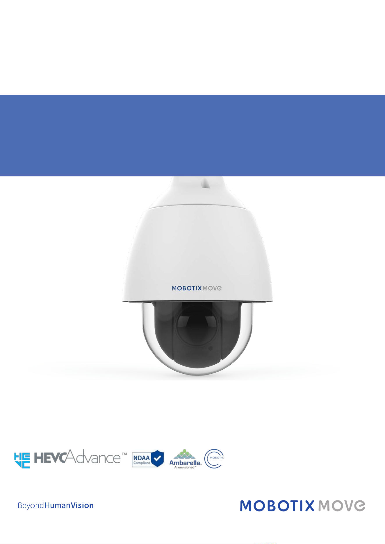
Package Contents
Check the package for the items listed below.
2MP Low-Light Video Analytics Speed Dome
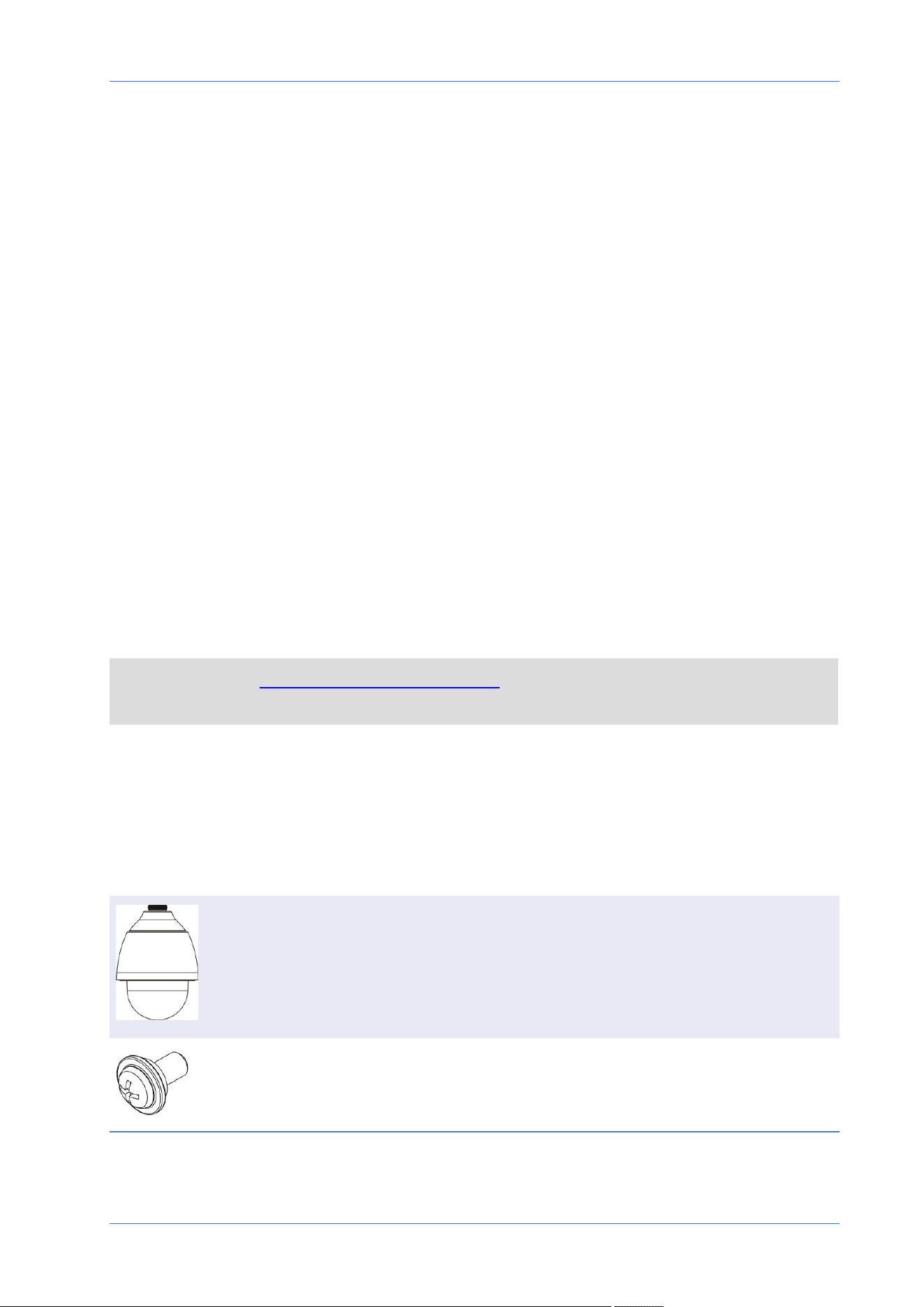
M4 security screw with sealing
10 / 130
3-pin power terminal block (for AC24V)
14-pin alarm and audio I/O terminal block
NOTE! To purchase a power adapter, contact MOBOTIX for further information.
CAUTION! Do not replace batteries of the camera. Risk of explosion may occur if the battery is
replaced by an incorrect type.
Dimensions
NOTE! Download the drilling template from the MOBOTIX website: www.mobotix.com> Sup-
port > Download Center > Marketing & Documentation> Drilling Templates.
CAUTION! Always print or copy the drilling template at 100% of the original size!
Overview
Dimensions
11 / 130
Overview
Accessories
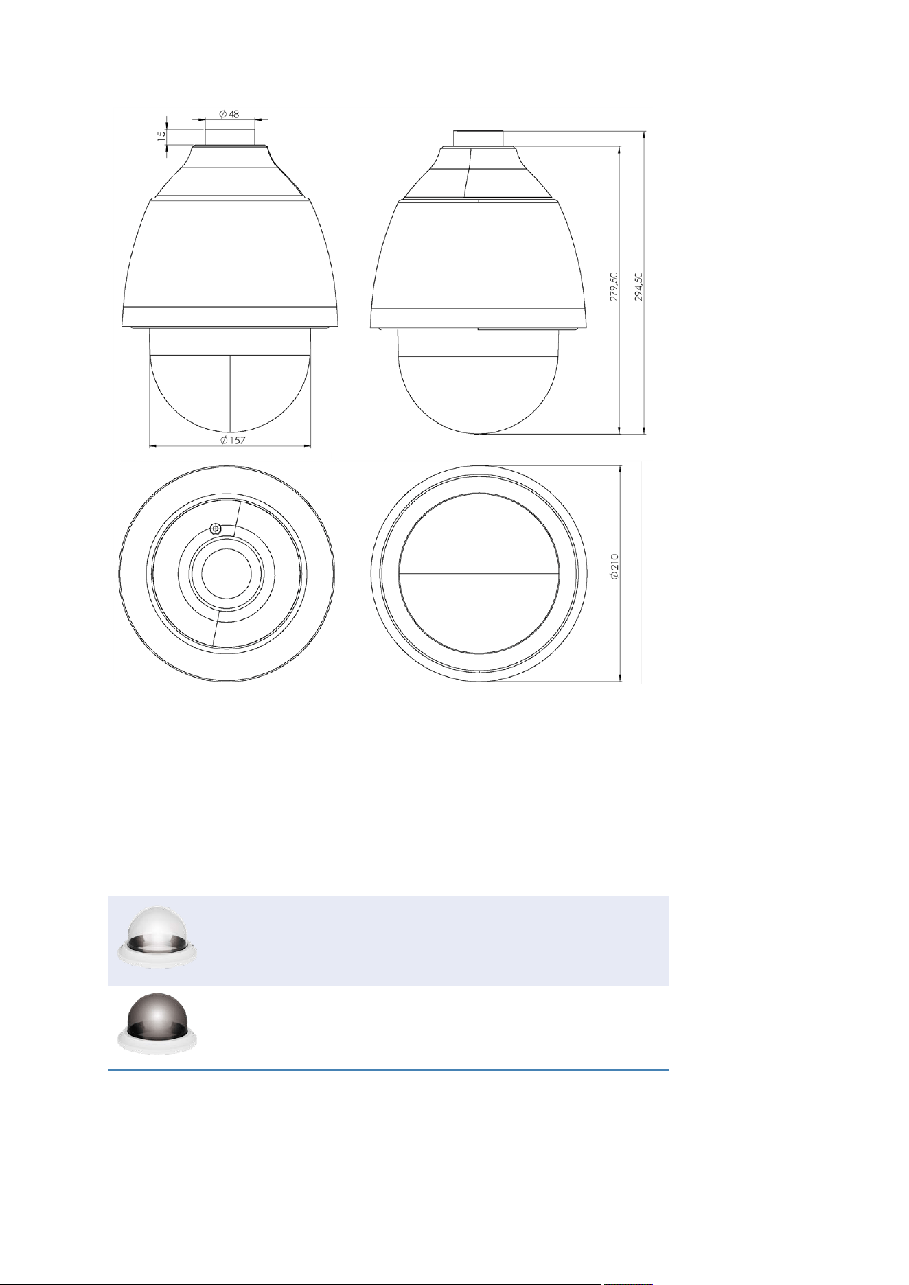
Fig. 1: 2MP Low-Light Video Analytics Speed Dome: All measurements in mm
Accessories
Picture Order Code Description
Mx-A-SD-DBC-EC Clear replacement dome with
EverClear coating
MX-A-SD-DBT-EC Tinted replacement dome with
EverClear coating
12 / 130
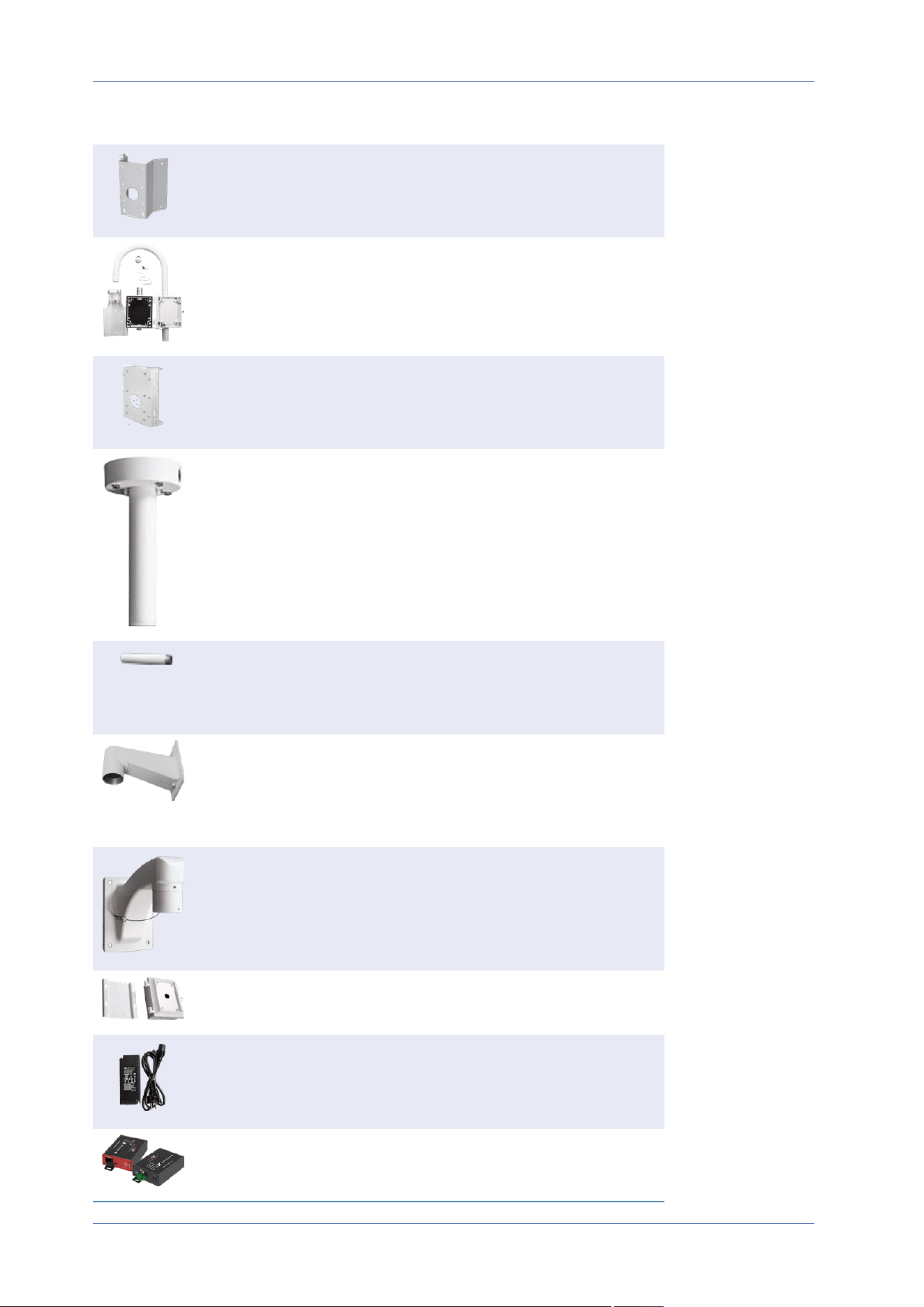
Picture Order Code Description
Mx-M-SD-C Corner Mount for MOBOTIX MOVE
cameras (only in combination with
Wall Mount Mx-M-SD-W/WM)
Mx-M-SD-GN Parapet Mount (Gooseneck) with
integrated junction box for MOBOTIX
MOVE cameras
Mx-M-SD-P Pole Mount for MOBOTIX MOVE cam-
eras (only in combination with Wall
Mount Mx-M-SD-W/WM)
Mx-M-SD-PM Pendant Mount Kit 25cm for
MOBOTIX MOVE cameras
Mx-M-SD-PMEXT Pendant mount extension 25cm for
use with Pendant Mount Kit Mx-M-
SD-PM
Mx-M-SD-W Wall Mount for MOBOTIX MOVE cam-
eras; can be combined with Pole
Mount Mx-M-SD-P or Corner Mount
Mx-M-SD-C
Mx-M-SD-WM Wall Mount with room for optional
junction box Mx-M-SD-WMJB for
MOBOTIX MOVE cameras
Mx-M-SD-WMJB Wall Mount Junction Box for
MOBOTIX MOVE cameras
Mx-NPA-UPOE1A-60W UPoE Network Power Injector 60W
Mx-A-ETP1A-2601-SET Media Converter Set Ethernet (PoE+)
– Twisted-Pair
Overview
Accessories
13 / 130

Connection
Camera Cabling
Camera Cabling
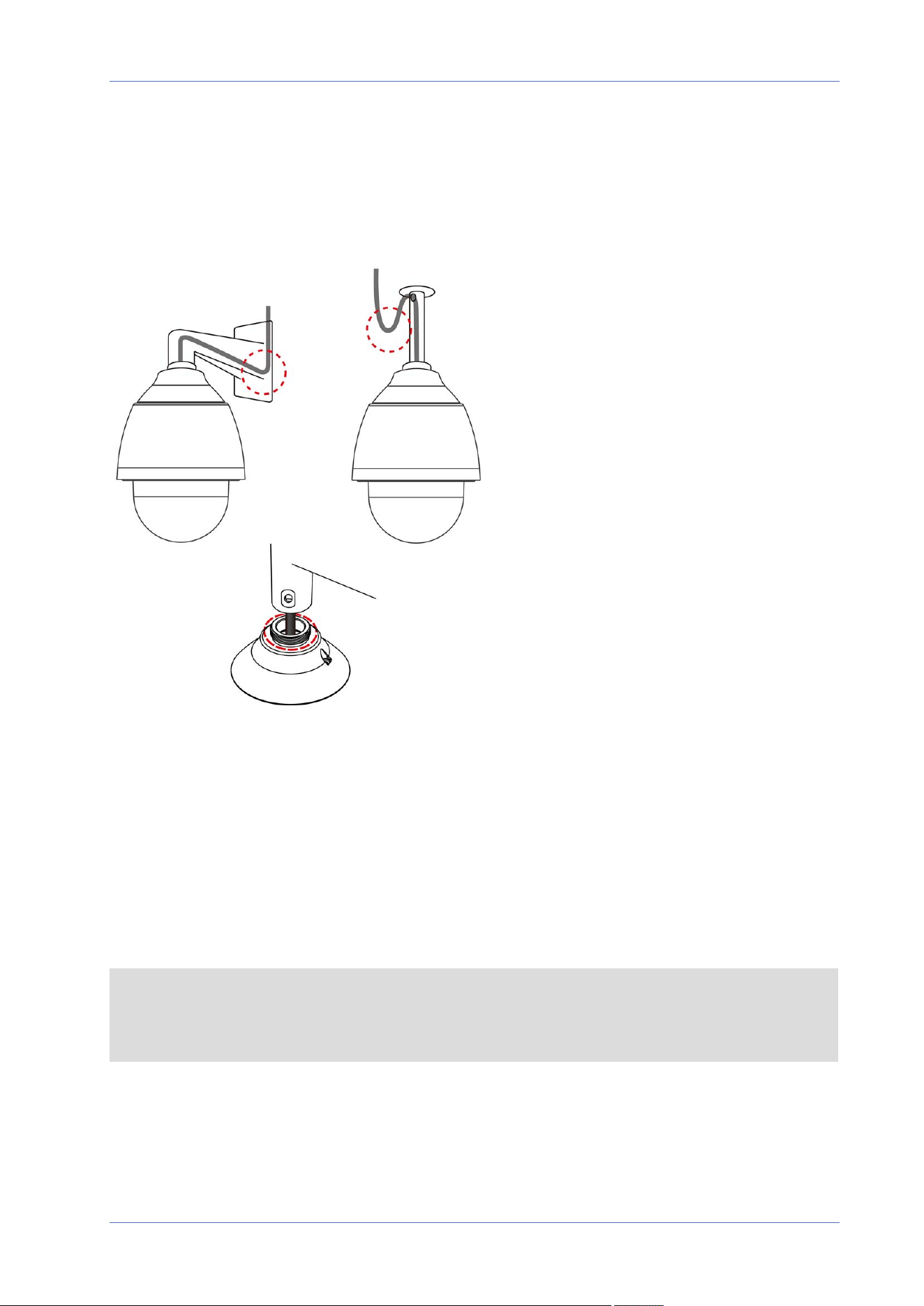
The camera is rated IP66 to prevent water from entering the camera. However, water might still enter
the camera if it is being improperly installed. Please make sure the warnings below are strictly fol-
lowed when installing the camera.
n
Place all cables and the adapter in dry and well-waterproofed environments, e.g. waterproof
boxes. This will prevent moisture from accumulating inside the camera and from penetrating
cables.
n
While running cables, slightly bend the cables to a U-shaped curve (see top images in figure
above) to make a low point. This will prevent water from entering the camera along the cables
from above.
n
The cable entry hole of the outdoor mounting kit (see bottom image in figure above) needs to
be sealed with thread seal tape to avoid water from entering the camera.
NOTE!
This camera must be installed by qualified personnel and the installation should conform to all
local codes.
16 / 130
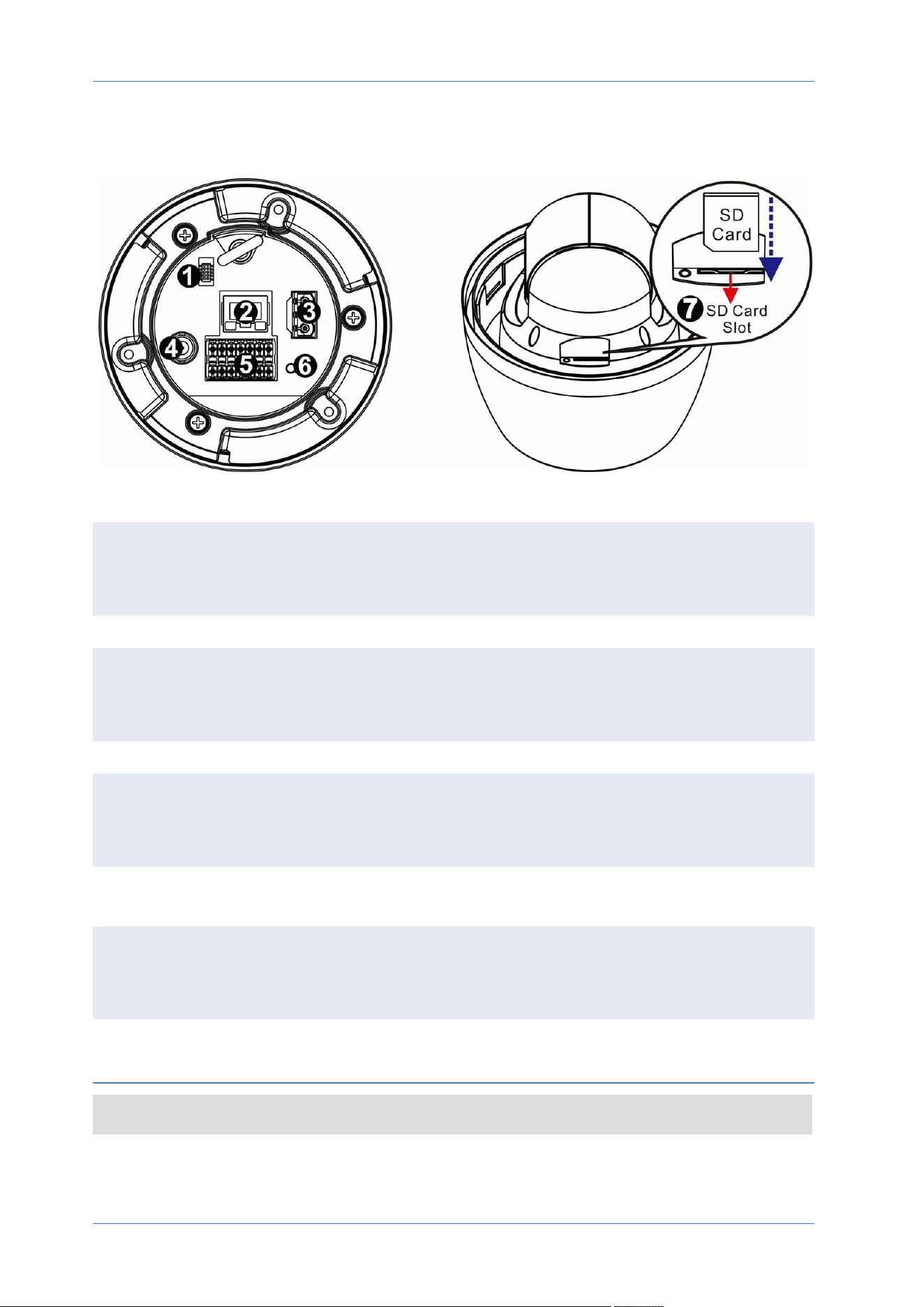
Camera Connectors
No. Connector Definition
1 Console Con-
nector
This connector is used to burn firmware into the camera when the cam-
era is returned for repair/maintenance. Please contact the camera man-
ufacturer for further information.
2 RJ-45 Port For network and PoE+ (Class4) connections
3 Power Con-
nector
(AC24V)
AC24V power connection (see Camera Cabling, p. 16 below)
4 BNC* For analog video output
5 Audio/Alarm
I/O & RS485
Connector**
Audio/Alarm I/O & RS485 connection (see Camera Cabling, p. 16 below)
6 Reset Button Press the button with a proper tool for at least 20 seconds to reset the
system to factory defaults.
7 SD Card Slot Open the dome cover to reveal the SD card slot. Use an SD card adapter
for microSD cards. Insert the SD card into the slot to store videos and
snapshots. Do not remove the SD card when the camera is powered on.
*Contact the manufacturer for a compatible BNC cable.
**Do NOT connect an external power supply to the alarm I/O connector of the camera.
NOTE! To purchase a power adapter, please contact MOBOTIX for further information.
Connection
Camera Cabling
17 / 130

Connection
Connecting Power
microSD Card Slot
n
Use an SD card adapter for microSD cards.
n
Insert the SD card into the card slot to store videos and snapshots.
n
Do not remove the SD card when the camera is powered on.
NOTE!
It is not recommended to record with the SD card for 24/7 continuously, as it may not be able to
support long term continuous data read/write. Please contact the manufacturer of the SD card for
information regarding the reliability and life expectancy.
Formatting the SD Card
After inserting a new or replacing a used SD card, the card must be formatted before the camera can
use it to record video streams.
1. Connect to the camera.
2. Open System> Storage Management> SD Card.
3. In the Device Setting section, click on Format to start the formatting process.
Once formatting has finished, the camera can use the SD card for recording.
Reset Button
Press the Reset button with a proper tool for at least 20 seconds to restore the factory defaults.
Connecting Power
Using Power over Ethernet (PoE)
Use a PoE+ switch (Class4) and connect the Ethernet cable to the RJ-45 port of the camera.
Using AC
To power up the camera, connect the AC power adapter to the power connector of the camera and
the power outlet.
18 / 130
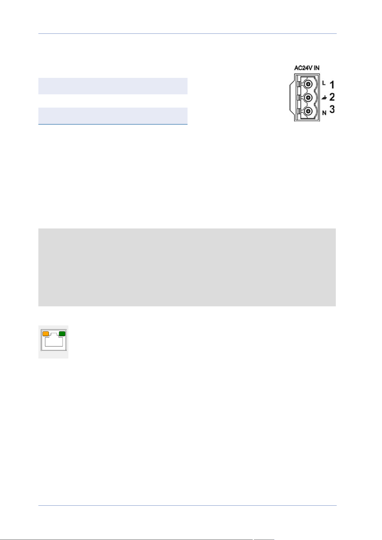
Diagram and Pin Definition for AC24V Power Connection
Pin Definition
1 AC24V L
2 GND
3 AC24V N
Connecting Ethernet Cable
Ethernet Cable Connection
Connect one end of the Ethernet cable to the RJ-45 connector of the camera and plug the other end
of the cable into the network switch or PC.
NOTE!
n
The length of the Ethernet cable should not exceed 100m/300ft.
n
Check the status of the link indicator and the activity indicator LEDs of the switch. If the
LEDs are unlit, please check the LAN connection.
n
In some cases, an Ethernet crossover cable may be needed when connecting the camera
directly to the PC.
Ethernet Connector LEDs
n
Green Link LED indicates good network connection.
n
Orange Activity LED flashes for network activity indication.
Connection
Connecting Ethernet Cable
19 / 130
Connection
Connecting Audio/Alarm I/O & RS485
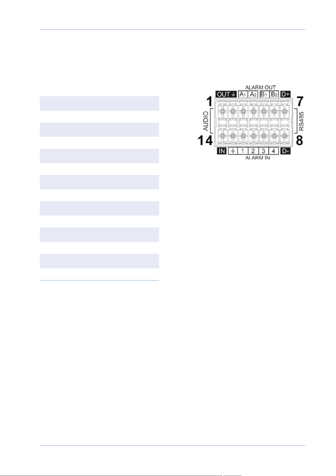
Connecting Audio/Alarm I/O & RS485
Please refer to the diagram and pin definition tables below for using the audio/alarm I/O & RS485
connection.
Pin Definition
1 Audio Out
2 GND (Audio I/O)
3 Alarm Out A1
4 Alarm Out A2
5 Alarm Out B1
6 Alarm Out B2
7 RS485 D+ (optional)
8 RS485 D- (optional)
9 Alarm In 4
10 Alarm In 3
11 Alarm In 2
12 Alarm In 1
13 GND (Alarm I/O and RS485)
14 Audio In
20 / 130

Installation
General Remarks
General Remarks
Read the instructions provided in this chapter thoroughly before installing the camera.
NOTE! This camera must be installed by qualified personnel and the installation must conform to
all local codes.
NOTE! Observe the MOBOTIX MOVE Installation Hints document to ensure optimum performance
of the camera features.
Camera Installation
The 2MP Low-Light Video Analytics Speed Dome cannot be mounted to walls or ceilings without
accessories. Please refer to Accessories, p. 12 to find the type of mount that is suitable for your situ-
ation.
To install the camera using one of these accessories, please refer to the corresponding Quick Install-
ation document available on www.mobotix.com> Support> Download Center> Marketing &
Documentation> Manuals in the Speed Dome Accessories section.
Camera Installation Notice
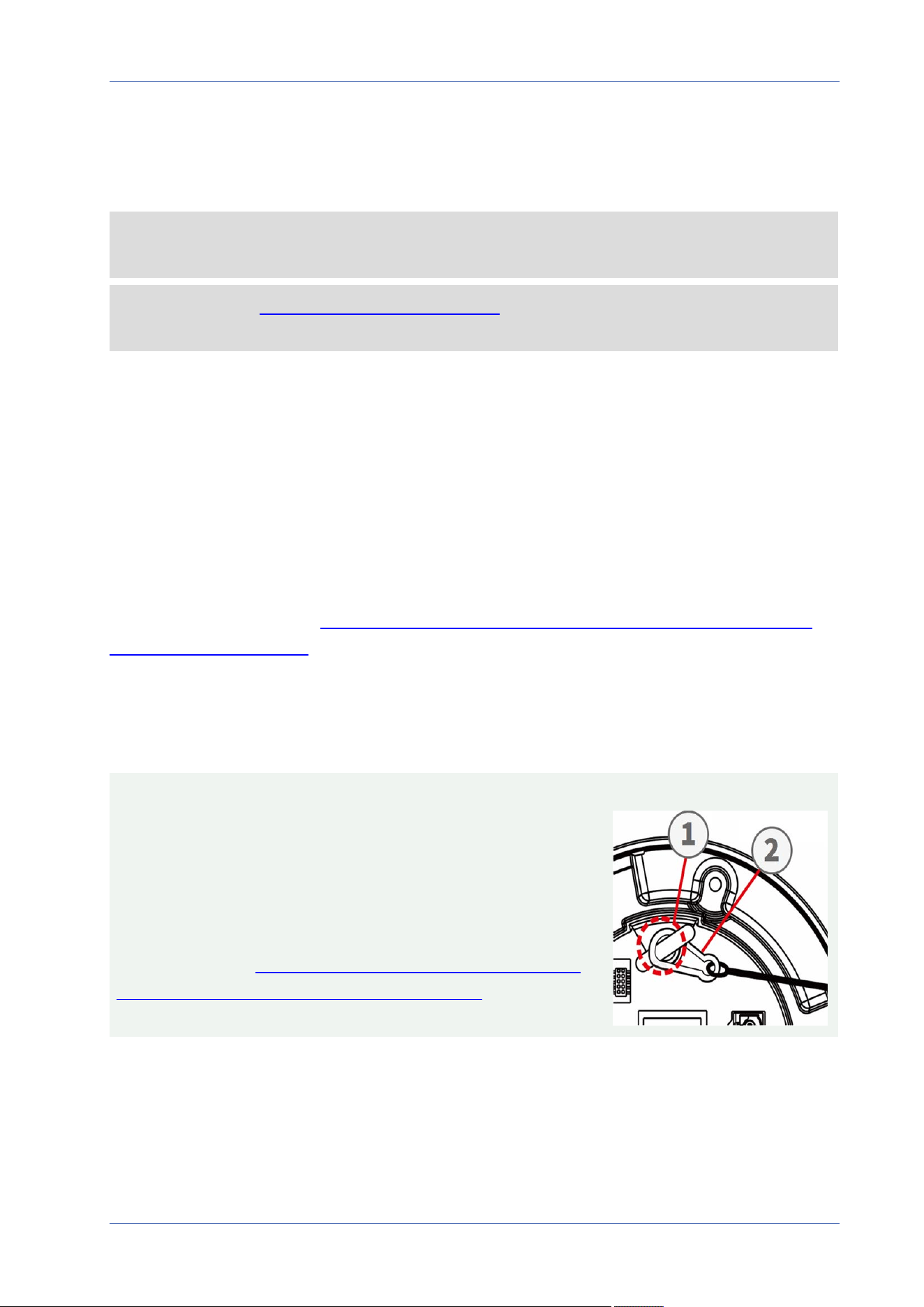
CAUTION!
For safety reasons, it is recommended to hook up the camera's
anti-drop ring ① to the anti-drop cable ② of the pendant/wall
mount when installing the camera.
For more information about installing the mounts and the anti-
drop cable, please see the corresponding Quick Installation doc-
ument available at www.mobotix.com> Support> Download
Center> Marketing & Documentation> Manuals in the
MOBOTIX MOVE Accessories section.
22 / 130

Installing to a Wall
You can install the camera to a wall using the following accessories:
n
Corner Mount Mx-M-SD-C (only in combination with SpeedDome Wall Mount Mx-M-SD-W/WM)
n
Parapet Mount Mx-M-SD-GN (Gooseneck) with integrated junction box
n
Pole Mount Mx-M-SD-P (only in combination with SpeedDome Wall Mount Mx-M-SD-W/WM)
n
Wall Mount Mx-M-SD-W can be combined with SD Pole Mount Mx-M-SD-P or Corner Mount
Mx-M-SD-C
n
Wall Mount Mx-M-SD-WM with room for optional junction box Mx-M-SD-WMJB
Installing to a Ceiling
You can install the camera to a ceiling using the following accessories:
n
Pendant Mount Kit 25cm Mx-M-SD-PM
n
Optional 25cm extension Mx-M-SD-PMEXT
Installation
Camera Installation
23 / 130


Configuration
System Requirements for Operating the Camera
System Requirements for Operating the
Camera
To operate the IP camera via web browser, please ensure the PC is in good network connection and
meets system requirements as described below.
Items System Requirements
Personal Computer Minimum:
n
Intel® Core™ i5-2430M @ 2.4 GHz
n
4 GB RAM
Recommended:
n
8 GB RAM
Operating System Windows 7 or later operating system
Web Browser Any current web browser
Network Card 10Base-T (10 Mbps), 100Base-TX (100 Mbps) or 1000Base-T operation
NOTE! The ITE is to be connected only to PoE networks without routing to the outside plant or
equivalent description.
Accessing the Camera
Accessing the Camera
The 2MP Low-Light Video Analytics Speed Dome supports all current browsers without requiring any
additional plug-ins or add-ons (e.g. for H.264/H.265/MJPEG support).
Camera Login
The default IP address of the camera is: 10.x.x.x. By default, the camera starts as DHCP client and
automatically tries to get an IP address from a DHCP server.
1. Enter the camera’s IP address in the URL bar of the web browser and hit “Enter”.
2. Enter the default username (admin) and password (meinsm).
NOTE! User names and passwords are case sensitive.
26 / 130
3. You will be prompted to set a new admin user password.
NOTE! The password can have between 6 and 14 characters (at least one digit, no special
characters allowed).
4. After setting a new password, you will be prompted to log in again. Remember to use the new
password.
Zoom and Focus Adjustment
The live image will be displayed on the Home page when the camera is successfully accessed. If
zoom or focus is not at the desired position, please use the function buttons on the Home page to
adjust zoom and focus.
NOTE! Refer to section Menu Reference, p. 31 of the Speed Dome WDR IP camera for more button
function details.
Configuration
Accessing the Camera
27 / 130
Configuration
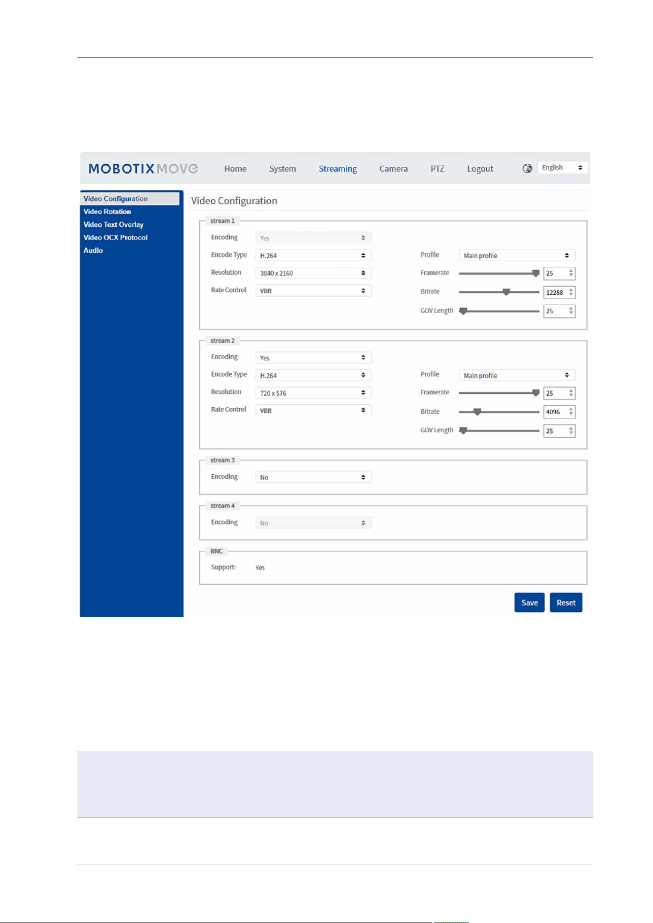
Setting the Video Resolution
Setting the Video Resolution
To edit the video configuration settings, select Streaming> Video Configuration.
Default Resolution
The following table lists the default resolution of the camera.
IP Camera Model Default Resolution
2MP Low-Light Video Analytics Speed
Dome
Mx-SD2A-230-LL-VA
WDR on/off H.265/H.264: 1920 × 1080 (30fps) +
MJPEG: 1080 × 720 (30fps)
28 / 130

Exporting/Importing Configuration Files
To export and import configuration files, you can access the Maintenance page on the user-friendly
browser-based configuration interface.
To edit the Maintenance settings, select System> Maintenance.
You can export configuration files to a specified location and retrieve data by uploading an existing
configuration file to the camera. This is especially convenient to make multiple cameras having the
same configuration.
Export
You can save the system settings by exporting the configuration file (.bin) to a specified location for
future use.
n
Click on the Export button, and the popup File Download window will come out.
n
Click on Save and specify a desired location for saving the configuration file.
Upload
To upload a configuration file to the camera, click on Browse to select the configuration file, and
then click on the Upload button for uploading.
Configuration
Exporting/Importing Configuration Files
29 / 130


31 / 130
Menu Reference
This section contains the following information:
The Camera Menu 34
The “Home” Tab 35
Function Items on Home Page 35
The “System” Tab 40
System 40
Security 42
Network 49
DDNS 57
Mail 58
FTP 58
HTTP 58
MxMessageSystem 59
Events (Alarm Settings) 60
Storage Management 77
Recording 80
Schedule 82
6

Menu Reference
File Location (Snapshots and Web Recording) 83
View Information 83
Factory Default 84
Software Version 85
Software Upgrade 85
Maintenance 85
The “Streaming” Tab 87
Video Configuration 88
Video Rotation 90
Video Text Overlay 91
Video OCX Protocol 92
Audio (Audio Mode and Bit Rate Settings) 92
The “Camera” Tab 95
Exposure 95
White Balance 97
Picture Adjustment 101
Color Style 102
IR Function 102
Noise Reduction 104
HDR Type 104
Gamma HDR 105
Image Stabilizer 105
Digital Zoom 106
Defog 106
Profile 106
TV System 107
The “PTZ” Tab 108
Preset 108
Cruise 109
Auto Pan 109
Sequence 110
Home Function 111
Tilt Range 112
Privacy Mask 112
PTZ Setting 114
32 / 130


Menu Reference
The Camera Menu
The Camera Menu
The camera’s Home Page shows these main tabs at the top:
The “Home” Tab, p. 35
You can monitor the live video of the targeted area.
The “System” Tab, p. 40
The administrator can set host name, system time, root password, network related settings, etc.
The “Streaming” Tab, p. 87
The administrator can configure video format, video compression, video OCX protocol, video frame
rate and audio compression in this page.
The “Camera” Tab, p. 95
This tab contains the camera-related settings and is only available for the administrator and user
accounts with camera control privileges.
The “PTZ” Tab, p. 108
This tab contains the PTZ-related settings and is only available for the administrator and user
accounts with camera control privileges.
The “Logout” Tab, p. 115
Click on the tab to log out of the camera system. Click on Login to log in again with a different user-
name and password, for example.
34 / 130
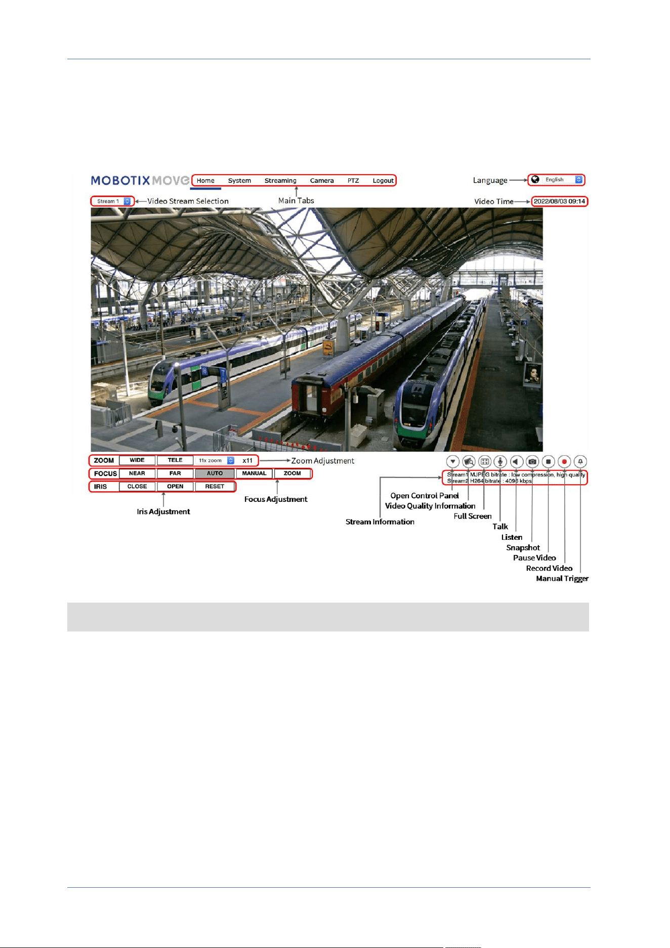
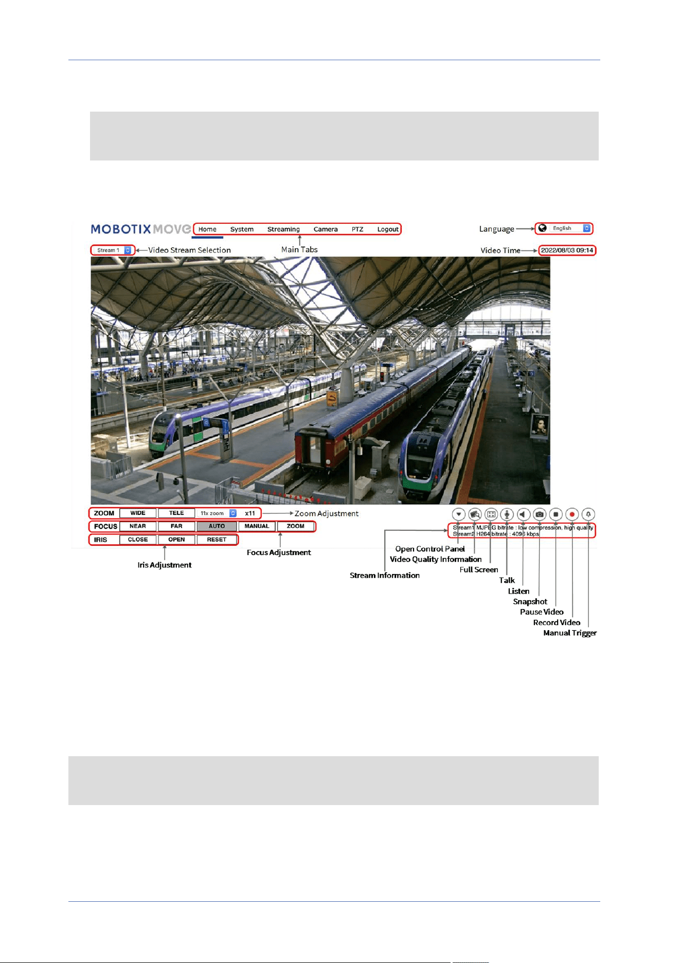
The “Home” Tab
Click on the tab Home to access the Home Page. There are several function buttons on this page.
Detailed information of each item is as described in the following section.
NOTE! The function buttons on the Home page will vary for different camera models.
Function Items on Home Page
Multiple Languages Support
The 2MP Low-Light Video Analytics Speed Dome supports different languages for the browser inter-
face, including German, English, Spanish, French, Italian, Japanese, Portuguese, Russian, Simplified
Menu Reference
The “Home” Tab
35 / 130
Menu Reference
The “Home” Tab
Chinese, and Traditional Chinese.
Display Stream Selection
According to the streaming setting, you can choose the one stream to display from the drop-down
menu.
Camera Info
Double-click on the live view pane, and the camera info window will pop up. You can instantaneously
check the basic information of the camera, such as IP address, network status, video format, etc.
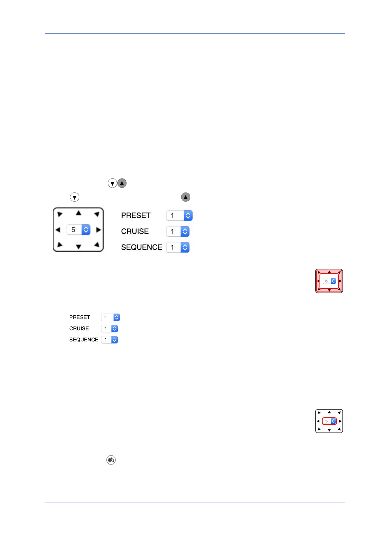
Control Panel (On/Off)
Click on to open the control panel and on to close it.
n
Pan/Tilt Direction Control
Click on the arrows to pan and tilt the camera into the corresponding direction.
n
Run Preset/Cruise/Sequence
n
Select a set of preset points you defined in Preset, p. 108.
n
Select a cruise path you defined in Cruise, p. 109.
n
Select a sequence line you defined in Preset, p. 108.
n
PT Speed
Select a number between 1 (slow) and 10 (fast) to set the pan/tilt speed of the cam-
era when using the Pan/Tilt Direction Control buttons.
Video Quality
Click to show/hide the video quality information including bitrate and compression.
36 / 130
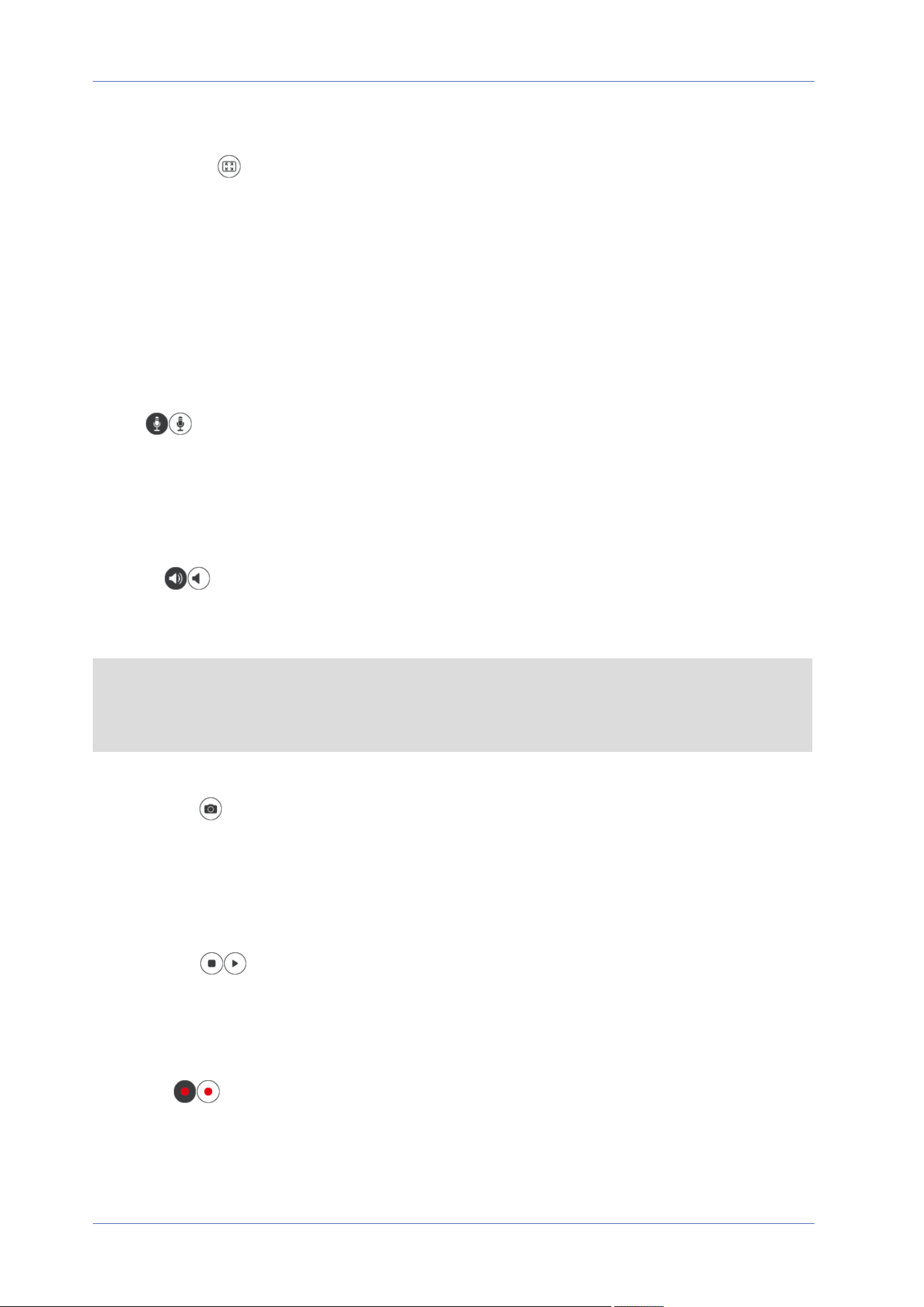
Full Screen
Use this button to switch the image display to full screen. Alternatively, right click on the Live Video
pane and select Fullscreen.
To exit full screen mode:
n
Tap Esc on the keyboard.
n
Double-click on the Live Video pane.
n
Right-click on the Live Video pane and select Normal view.
Talk (On/Off)
Talk function allows the local site talks to the remote site. Click on the button to switch it to On/Off.
Users must select the suitable transmission mode under this path: Streaming> Audio to enable this
function.
Listen (On/Off)
Click on Listen to mute/activate the audio. Users must select the suitable transmission mode under
Streaming> Audio to enable this function.
NOTE! Both Talk and Listen functions are only available for user accounts that have been granted
this privilege by the administrator. Please see the Talk/Listen section in System> Security>
User, p. 42 for further details.
Snapshot
Click on the button and the JPEG snapshots will automatically be saved in the appointed place. The
default place of saving snapshots is: C:\. To change the storage location, please see File Location
(Snapshots and Web Recording), p. 83 for further details.
Live View (Pause/Restart)
Click on Pause to disable video streaming, the live video will be displayed as black. Click on Restart
to show the live video again.
Record (On/Off)
Click on Record and the Live View through the web browser will be directly recorded to the specific
location on the local hard drive, which could be configured in the File Location page. The default
Menu Reference
The “Home” Tab
37 / 130
Menu Reference
The “Home” Tab
storage location for the web recording is: C:\. Please see File Location (Snapshots and Web Record-
ing), p. 83 for further details.
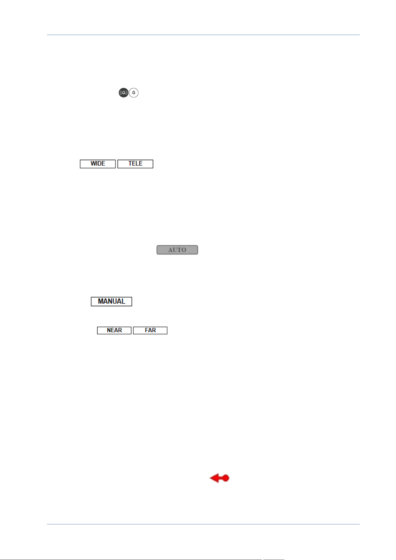
Manual Trigger (On/Off)
Click on Manual Trigger to activate/deactivate the manual trigger. Please see Manual Trigger, p. 70
for further details.
Zoom Adjustment
Wide/Tele
Hold the WIDE/TELE button, and implement continuous zoom adjustment.
For zoom lens models, optical zoom in/out functions can also be implemented by moving the cursor
to the live video pane and scrolling the mouse wheel in Normal View display mode.
Focus Adjustment
n
Auto Focus (Continuous AF)
Click on the Auto button to enable AF mode. In this mode, the camera will keep in focus auto-
matically and continuously regardless of zoom changes or any view changes. The focus status
will also be displayed above the live video pane.
n
Manual
Click on Manual, and you can adjust the focus manually via the Near/Far buttons.
n
Near/Far
Hold the Near/Far button, and implement continuous focus adjustment. The focus status will
also be displayed above the live video pane.
Iris Adjustment
n
Close: Closes the iris (image gets darker).
n
Open: Opens the iris (image gets brighter).
n
Reset: Resets the iris to the default setting.
Pan/Tilt Control
In the live video pane, left click and drag the pointer in any direction to move the camera.
38 / 130

Set Center Mode
In center mode, you can click on any point in the live image and the camera will move this point to
the center of the image.
n
Right-click on the live video pane and select Set Center Mode.
n
Click on the point of interest and the camera moves this point to the center of the live image.
To end center mode, right-click on the live video pane and select Set Emulated Joystick Mode to
return to the regular pan/tilt direction control (see Pan/Tilt Control, p. 38 above).
Optical/Digital Zoom Control
n
Normal View display mode:
Zoom in/out by moving the cursor to the live video pane and rotate the mouse wheel.
n
Full Screen display mode:
Rotate the mouse wheel anywhere to zoom in/out.
Digital zoom is only available if it has been activated in Camera> Digital Zoom (see Digital Zoom,
p. 106). Once the camera reaches the limit of its optical zoom, it will automatically switch to digital
zoom.
Menu Reference
The “Home” Tab
39 / 130
Menu Reference
The “System” Tab
The “System” Tab
NOTE! Only administrators can access the System configuration page.
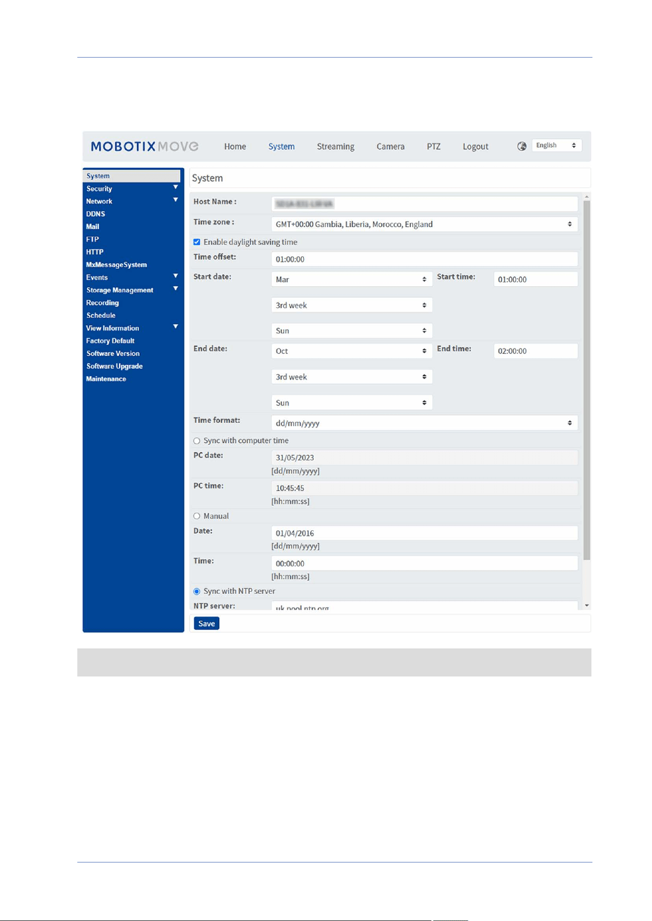
System
To edit the system settings, select System> System.
40 / 130

Host Name
The name is for camera identification. If alarm actions (see Triggered Actions (Common to All Event
Types), p. 60) are enabled and is set to send alarm messages by Mail/FTP, the host name entered
here will be displayed in the alarm message.
Time Zone
Select the time zone from the drop-down menu according to the location of the camera.
Enable Daylight Saving Time
To enable DST, please check the item and then specify the time offset and the DST duration. The
format for time offset is [hh:mm:ss]; for instance, if the amount of time offset is one hour, please
enter “01:00:00” into the field.
Time format
Choose a time format (yyyy/mm/dd or dd/mm/yyyy) from the drop-down menu. The format of the
date and time displayed above the live video window will be changed according to the selected
format.
Sync with Computer Time
Select the item, and video date and time display will synchronize with the PC’s.
NOTE! Users MUST click on Save to confirm the setting. Otherwise, the time will not be synced.
Manual
The administrator can set video date and time manually. Entry format should be identical with the
examples shown next to the enter fields.
Sync with NTP Server
Network Time Protocol (NTP) is an alternate way to synchronize the camera’s clock with a NTP
server. Please specify the server that is wished to synchronize in the entry field. Then select an
update interval from the drop-down menu. For further information about NTP, please open the web
site www.ntp.org.
NOTE! The synchronization will be done every time the camera boots up.
Menu Reference
The “System” Tab
41 / 130

Menu Reference
The “System” Tab
Click on Save to apply and store the settings.
Security
To edit the security settings, select System> Security.
Click on Security, there will be a drop-down menu with tabs including User, HTTPS, IP Filter, and
IEEE 802.1X.
User
To edit the user settings, select System> Security> User.
Admin Password
This item is for the administrator to reset password. Enter the new password in Admin password
and Confirm password. The input characters will be displayed as dots for security purposes. Click on
Save to confirm the changes. After the changes are confirmed, the web browser will ask the admin-
istrator to login again using the new password.
NOTE! The password can have between 6 and 14 characters (at least one digit, no special char-
acters allowed).
Add User
This item is for the administrator to add new users. Enter the new user’s name in User name and the
password in User password. Username can be up to 16 characters, and the password can have
between 6 and 14 characters (at least one digit, no special characters). Click on Add to add the new
user. The name of the new added user will be displayed in the User name drop-down menu under
Manage User. There is a maximum of twenty user accounts.
Activate the boxes below to give privileges for functions:
n
I/O access
This item supports fundamental functions that enable users to view the live video when access-
ing to the camera.
n
Camera control
This item allows the appointed user to change camera parameters on the Camera and Pan
Tilt setting page.
42 / 130

Manage User
n
Delete user
Pull down the User name drop-down menu and select the username that is wished to be
deleted. Click on Delete to remove the selected name.
n
Edit user
Pull down the User name drop-down menu and select the username. Click on Edit and a
popup window will appear. In the appeared window, enter the new user password and reset
the privileges. Click on Save to confirm the changes. Then click on Close to complete the edit-
ing.
HTTP Authentication Setting
This setting allows secured connections between the IP camera and web browser by enforcing
access controls to web resources. When users approach to the web browser, it’ll ask for username
and password, which protects the camera settings or live streaming information from snooping.
There are two security models available: Basic and Digest. Refer to the descriptions below for more
details.
n
Basic
This mode can only provide basic protection for the connection security. There will still be
risks for the password being intercepted.
n
Digest
Digest mode is a safer option for protection. The password is sent in an encrypted format to
prevent it from being stolen.
NOTE! Users MUST click on Save to apply the setting.
Streaming Authentication Setting
This setting provides security against unauthorized users from getting streaming via Real Time
Streaming Protocol (RTSP). If the setting is enabled, users will be requested to enter user name and
password before viewing the live streams. There are three security modes available: Disable, Basic
and Digest. Refer to the descriptions below for more details.
n
Disable
If disable mode is selected, there will be no security provided to against unauthorized access.
Users will not be asked to input user name and password for authentication.
n
Basic
This mode can only provide basic protection for the live streams. There will still be risks for
the password being intercepted.
Menu Reference
The “System” Tab
43 / 130

Menu Reference
The “System” Tab
n
Digest
Digest mode is a safer option for protection. The password is sent in an encrypted format to
prevent it from being stolen.
NOTE! Users MUST click on Save to apply the setting.
Enable Account Lockout Function
The Account Lockout Function is to lock out an account when someone tries to log on unsuccessfully
several times in a row. To protect user’s account, “Account Lockout Function’’ is activated when mul-
tiple login failures occur. Check the box Enable Account Lockout Function and enter the number of
threshold and duration.
n
Threshold
Threshold is a maximum number of login attempts, ranging from 5-20 times. The default value
is 5 (attempts).
n
Duration
Duration is the length of time that the account remains locked once the account lockout func-
tion is triggered, ranging from 1-60 minutes (default is 10 minutes).
Auto Log Off Setting
If Enable log off timer is enabled, the camera will log off the current user after the specified number
of minutes without interaction have passed (default is 5 minutes).
HTTPS
To edit the HTTPS settings, select System> Security> HTTPS.
HTTPS allows secure connections between the camera and the web browser using Secure Socket
Layer (SSL) or Transport Layer Security (TLS), which protects camera settings and user-
name/password inforomation from snooping. It is required to install a self-signed or generated cer-
tificate or a CA-signed certificate for implementing HTTPS.
To use HTTPS on the camera, an HTTPS certificate must be installed. The HTTPS certificate can be
obtained by either creating and sending a certificate request to a Certificate Authority (CA), by
uploading a certificate, or by creating a self-signed HTTPS certificate.
NOTE! On MOBOTIX MOVE cameras, a certificate has already been installed. If you are not required
to use a specific certificate (provided by your network administrator), you can use the pre-installed
certificate.
44 / 130

Enable HTTPS
Check the box to enable HTTPS secure connection. Once enabled, choose one of the following
secure modes.
n
HTTP & HTTPS
Under this mode, HTTP & HTTPS secure connections are enabled.
n
HTTPS only
Under this mode, the secure connection is ensured by HTTPS only.
Click on Save to apply and store the settings.
Install new certificate
Pull down the Install new certificate drop-down list and select the certificate type. Choose one
from the following types.
n
Generate Self-signed Certificate
Before a CA-issued certificate is obtained, you can create and install a self-signed certificate
first.
Beneath Generate Self-signed Certificate, click on Create and provide the requested inform-
ation as outlined under Provide the Certificate Information, p. 46.
NOTE! The self-signed certificate does not provide the same high level of security as when
using a CA-issued certificate.
n
Generate Certificate Request
Click on Generate Certificate Request to create a certificate request for obtaining a signed
certificate from CA. Provide the requested information as outlined under Provide the Cer-
tificate Information, p. 46.
When the request is complete, the subject of the created request will be shown in the field.
Click on Properties below the Subject field, copy the PEM-formatted request and send it to
the selected CA.
When the signed certificate is returned, install it by uploading the signed certificate (see
Upload Private Key/Certificate, p. 45).
Upload Private Key/Certificate
n
Do one of the following:
n
If you have a private key file, click on Browse beneath Private key and select the
private key file.
n
If you have a certificate file, click on Browse beneath Certificate and select the cer-
tificate file.
Menu Reference
The “System” Tab
45 / 130

Menu Reference
The “System” Tab
n
Click on Upload and wait until the installation is finished.
Click on Save to apply and store the settings.
Provide the Certificate Information
To create a Self-signed HTTPS Certificate or a Certificate Request to CA, please enter the information
as requested.
Information Item Create Self Signed Certificate Create Certificate Request
Country ✓ ✓
State or Province ✓ ✓
Locality ✓ ✓
Organization ✓ ✓
Organizational Unit ✓ ✓
Common Name ✓ ✓
Valid Days ✓ -
n
Country
enter a two-letter combination code to indicate the country the certificate will be used in. For
instance, type in “US” to indicate United States.
n
State or Province
Enter the local administrative region.
n
Locality
Enter other geographical information.
n
Organization
Enter the name of the organization to which the entity identified in “Common Name” belongs.
n
Organization Unit
Enter the name of the organizational unit to which the entity identified in “Common Name”
belongs.
n
Common Name
Indicate the name of the person or other entity that the certificate identifies (often used to
identify the website).
n
Valid Days
Enter the period in days (1 to 9999) to indicate the valid period of certificate.
Click on OK to save the Certificate Information after completing the setting.
46 / 130

IP Filter
To edit the IP filter settings, select System> Security> IP Filter.
With IP Filter, you can allow or deny specific IP addresses from accessing the camera.
Enable IP Filter
Check the box to enable the IP Filter function. Once enabled, the listed IP addresses (IPv4) in the
Filtered IP Addresses list box will be allowed/denied to access the camera.
Select Allow or Deny from the drop-down menu and click on Apply to determine the IP filter beha-
vior.
Add IP Address
Input IP address at the blank space below the Filtered IP Address list and click Add. The newly-
added address will be shown in the list. Up to 256 IP address entries can be specified.
In addition, to filter a group of IP addresses, enter an address at the blank space followed with a
slash and a number ranging from 1 to 31, e.g. 192.168.2.81/30. The number after the slash can
define how many IP addresses will be filtered. For details, please refer to Example: Filtering a Group
of Consecutive IP Addresses, p. 47 below.
Delete IP Address
To remove an IP address from the Filtered IP Address list, select the address and click on Delete.
Example: Filtering a Group of Consecutive IP Addresses
1. Convert 192.168.2.81/30 to binary numbers (see Appendix B: Converting IP Addresses from
Decimal to Binary, p. 116). The binary numbers are 11000000.10101000.00000010.01010001. The
number “30” after the slash is referring to the first 30 digits of the binary numbers.
Menu Reference
The “System” Tab
47 / 130

Menu Reference
The “System” Tab
2. Convert a few IP addresses before and after 192.168.2.81 to binary numbers. Then compare their
first 30 digits with the binary numbers of 192.168.2.81.
1. Convert 192.168.2.80 to binary numbers. The binary numbers are
11000000.10101000.00000010.01010000. The first 30 digits are the same with the binary num-
bers of 192.168.2.81, thus 192.168.2.80 will be filtered.
2. Convert 192.168.2.79 to binary numbers. The binary numbers are
11000000.10101000.00000010.01001111. The first 30 digits are different with the binary num-
bers of 192.168.2.81, thus 192.168.2.79 will not be filtered. This also means the IP addresses
before 192.168.2.79 will not be filtered. Therefore, you can stop converting the IP addresses
before 192.168.2.79 to binary numbers.
3. Repeat the same procedure in “a” with the IP addresses after 192.168.2.81. Stop when the
situation occurs in “b” happened. Namely, the 30th digit of the binary numbers of IP address
192.168.2.84 is different, and will not be filtered.
As a result, the IP addresses 192.168.2.80 to 192.168.2.83 will be filtered when entering
192.168.2.81/30. The following table clearly shows the 30
th
digit of the binary numbers of IP
addresses 192.168.79 and 192.168.84 are different from the others. Therefore, these two IP addresses
will not be filtered.
IP Addresses Binary Numbers
192.168.2.79 11000000.10101000.00000010.01001111
192.168.2.80 11000000.10101000.00000010.01010000
192.168.2.81 11000000.10101000.00000010.01010001
192.168.2.82 11000000.10101000.00000010.01010010
192.168.2.83 11000000.10101000.00000010.01010011
192.168.2.84 11000000.10101000.00000010.01010100
IEEE 802.1X
To edit the IEEE 802.1x settings, select System> Security> IEEE 802.1X.
The camera is allowed to access a network protected by 802.1X/EAPOL (Extensible Authentication
Protocol over LAN).
Choose On to enable the IEEE 802.1X function.
Select one among the four protocol types: EAP-MD5, EAP-TLS, EAP-TTLS and EAP-PEAP.
Users need to contact with the network administrator for gaining certificates, user IDs and pass-
words.
48 / 130

CA Certificate
The CA certificate is created by the Certification Authority for the purpose of validating itself.
Upload the certificate for checking the server’s identity.
Client Certificate/Private Key
Upload the Client Certificate and Private Key for authenticating the camera itself.
Settings
n
Identity
Enter the user identity associated with the certificate. Up to 16 characters can be used.
n
Private Key Password
Enter the password (maximum 16 characters) for user identity.
Enable IEEE 802.1X
Check the box to enable IEEE 802.1X.
Click on Save to apply and store the settings.
Network
To edit the network settings, select System> Network.
Click on Network, there will be a drop-down menu with tabs including Basic, QoS, SNMP, and
UPnP.
Basic
To edit the basic settings, select System> Network> Basic.
This setting page is for setting a new IP address for the camera, configuring other network-related
parameters and activating IPv6 address (if the network supports it).
General
This setting menu is for configuring a new IP address for the camera. To setup an IP address, please
find out the network type first. Contact the network provider for it. Then refer to the network type
and follow the instructions to setup the IP address.
NOTE! If the network type is Point-to-Point Protocol over Ethernet (PPPoE), please obtain the
PPPoE username and password from the network provider.
Menu Reference
The “System” Tab
49 / 130

Menu Reference
The “System” Tab
n
Get IP address automatically (DHCP)
Select the item and click Save to confirm the new setting. A note for camera system reboot
will appear. Click OK and the camera system will restart. The camera will be assigned with a
new IP address. Close the web browser and search the camera through the installer program:
DeviceSearch.exe. Refer to the steps below to connect the camera through “DeviceSearch” soft-
ware.
NOTE! Before searching the camera through DeviceSearch.exe, please record the camera’s
MAC address, which can be found on the label or on the package container of the camera,
for later use and identification in the future.
n
Double-click on the program DeviceSearch.exe.
n
After its window appears, click on Device Search on the top. All the finding IP devices will be
listed in the page.
n
Find the camera by its MAC address.
n
Then double-click or right click and select Browse to access the camera directly by the web
browser.
n
A prompt window requesting for the username and the password will appear. Enter the user-
name and the password to login to the camera.
50 / 130

n
Use fixed IP address
Select the item and insert the new IP address, e.g. 192.168.7.123. Note that the inserted IP
address should be in the same LAN as the PC’s IP address. Then go to the Default gateway
(explained later) blank and change the setting, e.g. 192.168.7.254. Click on Save to confirm
the new setting. A note for system restart will appear, click OK and the camera system will
restart. Wait for 15 seconds. The camera’s IP address in the URL bar will be changed, and
users have to login again.
When using a static IP address to connect the camera, you can access the camera by input-
ting the IP address in the URL bar and hit Enter on the keyboard. Alternatively, you can
access the camera by the installer program: DeviceSearch.exe. Refer to the steps below to
connect the camera through “DeviceSearch” software with a static IP address.
n
Double-click on the program DeviceSearch.exe.
n
After its window appears, click on Device Search on the top. All the finding IP devices will be
listed in the page.
n
Find the camera by its IP address.
n
Then double-click or right click and select Browse to access the camera directly by the web
browser.
n
A prompt window requesting for the username and the password will appear. Enter the user-
name and the password to login to the camera.
n
IP address
This is necessary for network identification.
n
Subnet mask
It is used to determine if the destination is in the same subnet. The default value is
“255.255.255.0”.
n
Default gateway
This is the gateway used to forward frames to destinations in different subnet. Invalid
gateway setting will fail the transmission to destinations in different subnet.
n
Primary DNS
Primary DNS is the primary domain name server that translates hostnames into IP
addresses.
n
Secondary DNS
Secondary DNS is a secondary domain name server that backs up the primary DNS.
n
Use PPPoE
For the PPPoE users, enter the PPPoE username and password into the enter fields.
Click on Save to apply and store the settings.
Menu Reference
The “System” Tab
51 / 130

Menu Reference
The “System” Tab
Advanced
The following introduces the camera’s Web Server port, RTSP port, MJPEG over HTTP port, and
HTTPS port.
n
Web Server port
The default web server port is 80. With the default web server port ‘80’, you can simply input
the IP address of the camera in the URL bar of a web browser to connect the camera. When
the web server port is changed to any number other than 80, users have to enter the camera’s
IP address followed by a colon and the port number. For instance, a camera whose IP address
is set as 192.168.0.100 and web server port as 8080 can be connected by entering
“http://192.168.0.100:8080” in the URL bar.
n
RTSP port
The default setting of RTSP Port is 554; the RTSP Port should be set as 554 or from the range
1024 to 65535.
n
MJPEG over HTTP port
This setting always uses port 80. To access the MJPEG stream over HTTP, open http://<ip
address>/live/stream<#>, where <#> is the number of the stream you want to show.
n
HTTPS port
The default setting of HTTPS Port is 443; the HTTPS Port should be set as 443 or from the
range 1024 to 65535.
NOTE! Please make sure the port numbers set above are not the same with each other; oth-
erwise, network conflict may occur.
n
RTSP URL
When users use RTSP players to view the live streaming, the camera provides the flexibility to
configure the streaming access name for stream 1 to stream 4. The streaming format is
rtsp://ip address:rtsp port/access name. Take a camera whose IP address is set as
192.168.0.100 for example, if users enter “liveview.1” in the blank of stream 1 access name, the
streaming address of stream 1 will be rtsp://192.168.0.100:554/liveview.1.
NOTE! The maximum length of the access name is 32 characters, and the valid characters
are A-Z, a-z, 0-9 and !#$%&’-.@^_~.
NOTE! For a list of default ports, please refer to AppendixC: List of Open/Closed IP Ports, p. 118.
Click on Save to apply and store the settings.
52 / 130

IPv6 Address Configuration
If the network supports IPv6, you can check the box beside Enable IPv6 and click Save. An IPv6
address will appear beside Address, and you can use it to connect to the camera.
Click on Save to apply and store the settings.
QoS
To edit the QoS (Quality of Service) settings, select System> Network> QoS.
QoS allows providing differentiated service levels for different types of traffic packets, which guar-
antees delivery of priority services especially when network congestion occurs. Adapting the Dif-
ferentiated Services (DiffServ) model, traffic flows are classified and marked with DSCP (DiffServ
CodePoint) values, and thus receive the corresponding forwarding treatment from DiffServ capable
routers.
DSCP Settings
The DSCP value range is from 0 to 63. The default DSCP value is 0 (DSCP disabled). The camera uses
the following QoS Classes:
n
Management DSCP
NOTE! The class consists of HTTP traffic: Web browsing.
n
Stream 1~4 DSCP
NOTE! You can set the Video DSCP of each stream.
n
Video DSCP
The class consists of applications such as MJPEG over HTTP, RTP/RTSP and
RTSP/HTTP.
NOTE! To enable this function, please make sure the switches/routers in the network support
QoS.
Click on Save to apply and store the settings.
VLAN
To edit the VLAN settings, select System> Network> VLAN.
Check the box Enable VLAN to activate the VLAN function. Enter the VLAN ID. The allowed range of
VLAN ID is from 1 to 4095. The default value is 20.
Menu Reference
The “System” Tab
53 / 130

Menu Reference
The “System” Tab
CoS
CoS stands for Class of Service. The higher the value of CoS is, the better transmission performance
will be. The value also determines the transmission priority among the following three classes:
n
Live Video
The value range is from 0 to 7.
n
Management
The value range is from 0 to 7.
SNMP
To edit the SNMP (Simple Network Management Protocol) settings, select System> Network>
SNMP.
With Simple Network Management Protocol (SNMP) support, the camera can be monitored and man-
aged remotely by the network management system.
SNMP v1/v2
n
Enable SNMP v1/v2
Select the version of SNMP to use by checking the box.
n
Read Community
Specify the community name that has read-only access to all supported SNMP objects. The
default value is “public”.
n
Write Community
Specify the community name that has read/write access to all supported SNMP objects (except
read-only objects). The default value is “private”.
SNMP v3
SNMP v3 supports an enhanced security system that provides protection against unauthorized users
and ensures the privacy of the messages. Users will be requested to enter security name, authen-
tication password and encryption password while setting the camera connections in the network
management system. With SNMP v3, the messages sent between the cameras and the network man-
agement system will be encrypted to ensure privacy.
n
Enable SNMP v3
Enable SNMP v3 by checking the box.
54 / 130

n
Security Name
The maximum length of the security name is 32 characters.
NOTE! The valid characters are A-Z, a-z, 0-9 and !#$%&’-.@^_~.
n
Authentication Type
There are two authentication types available: MD5 and SHA. Select SHA for a higher security
level.
n
Authentication Password
The authentication password must be 8 characters or more. The input characters will be dis-
played as dots for security purposes.
NOTE! The valid characters are A-Z, a-z, 0-9 and !#$%&’-.@^_~.
n
Encryption Type
There are two encryption types available: DES and AES. Select AES for a higher security level.
n
Encryption Password
The minimum length of the encryption password is 8 characters and the maximum length is
512 characters. The input characters will be displayed as dots for security purposes. The
encryption password can also be left blank. However, the messages will not be encrypted to
protect privacy.
NOTE! The valid characters are A-Z, a-z, 0-9 and !#$%&’-.@^_~.
Traps for SNMP v1/v2/v3
Traps are used by the camera to send messages to a management system for important events or
status changes.
n
Enable Traps
Check the box to activate trap reporting.
n
Trap address
Enter the IP address of the management server.
n
Trap community
Enter the community to use when sending a trap message to the management system.
Trap Option
n
Warm Start
A Warm Start SNMP trap signifies that the SNMP device, i.e. IP camera, performs software
reload.
Menu Reference
The “System” Tab
55 / 130

Menu Reference
The “System” Tab
Click on Save to apply and store the settings.
UPnP
To edit the UPnP settings, select System> Network> UPnP.
UPnP Setting
n
Enable UPnP
When the UPnP is enabled, whenever the camera is presented to the LAN, the icon of the con-
nected cameras will appear in My Network Places to allow for direct access.
NOTE! To enable this function, please make sure the UPnP component is installed on the
computer. Please see Appendix A: Installing UPnP Components, p. 116 for the installation
procedure.
n
Enable UPnP port forwarding
When the UPnP port forwarding is enabled, the camera is allowed to open the web server port
on the router automatically.
NOTE! To enable this function, please make sure that the router supports UPnP and it is
activated.
n
Friendly name
Set a name for the camera for identity.
Click on Save to apply and store the settings.
OpenVPN
This camera uses OpenVPN to implement a virtual private network (VPN). A VPN establishes secure
point-to-point or site-to-site connections between networks and computers (e.g. for remote workers).
Your VPN gateway administrator will provide the values for the settings below.
n
OpenVPN
Select Enabled to activate VPN.
n
Server address
Enter the IP address or DNS name of the VPN gateway you want to use.
n
Server port
Enter the server port of the specified VPN gateway.
n
Communication protocol
Select the type of protocol for the specified VPN gateway.
56 / 130

n
Cipher
Select the cipher that is being used to encode the network data.
n
CA certificate
Click on Browse to upload a new certification authority (CA) certificate file (ask your VPN
administrator for details).
n
Client certificate
Click on Browse to upload a new client certificate file (ask your VPN administrator for
details).
n
Private key
Click on Browse to upload a new private key file (ask your VPN administrator for details).
Click on Save to apply and store the settings.
Bonjour
Bonjour (also known as Zero-configuration networking or zeroconf) is a method for establishing
automatic peer-to-peer networks (i.e. without dedicated network services, such as DHCP or DNS
servers).
Activate Enable Bonjour to use this feature.
Click on Save to apply and store the settings.
DDNS
To edit the DDNS settings, select System> DDNS.
Dynamic Domain Name System (DDNS) allows a host name to be constantly synchronized with a
dynamic IP address. In other words, it allows those using a dynamic IP address to be associated to
a static domain name so others can connect to it by name.
n
Enable DDNS
Check the item to enable DDNS.
n
Provider
Select one DDNS host from the provider list.
n
Host name
Enter the registered domain name in the field.
n
Username/E-Mail
Enter the username or E-mail required by the DDNS provider for authentication.
Menu Reference
The “System” Tab
57 / 130

Menu Reference
The “System” Tab
n
Password/Key
Enter the password or key required by the DDNS provider for authentication.
Mail
To edit the mail settings, select System> Mail.
The administrator can send an E-mail via Simple Mail Transfer Protocol (SMTP) when an alarm is
triggered. SMTP is a protocol for sending E-mail messages between servers. SMTP is a relatively
simple, text-based protocol, where one or more recipients of a message are specified and the mes-
sage text is transferred.
Two sets of SMTP can be configured. Each set includes SMTP Server, Account Name, Password and E-
mail Address settings. For SMTP server, contact the network service provider for more specific inform-
ation.
Click on Save when finished. Then, please click on Test to check the connection between the camera
and the specified SMTP server.
FTP
To edit the FTP settings, select System> FTP.
The administrator can set the camera to send the alarm messages to a specific File Transfer Protocol
(FTP) site when an alarm is triggered. You can assign alarm message to up to two FTP sites. Enter the
FTP details, which include server, server port, username, password and remote folder, in the fields.
Click on Save when finished. Then, please click on Test to check the connection between the camera
and the specified FTP server.
HTTP
To edit the HTTP settings, select System> HTTP.
An HTTP Notification server can listen for the notification messages from the cameras by triggered
events. Enter the HTTP details, which include server name (for instance, http://192.168.0.100/ad-
min.php), username, and password in the fields. Alarm triggered and Motion Detection notifications
can be sent to the specified HTTP server.
Click on Save to apply and store the settings.
58 / 130
NOTE! Please see Events> Application>Send HTTP Notification, p. 63 for the HTTP notification
settings.
MxMessageSystem
This system allow exchanging network messages between computers and cameras and is used for
advanced signaling of events.
To edit the MxMessageSystem settings, select System> MxMessageSystem.
The camera can send notifications via the MxMessageSystem by triggered events.
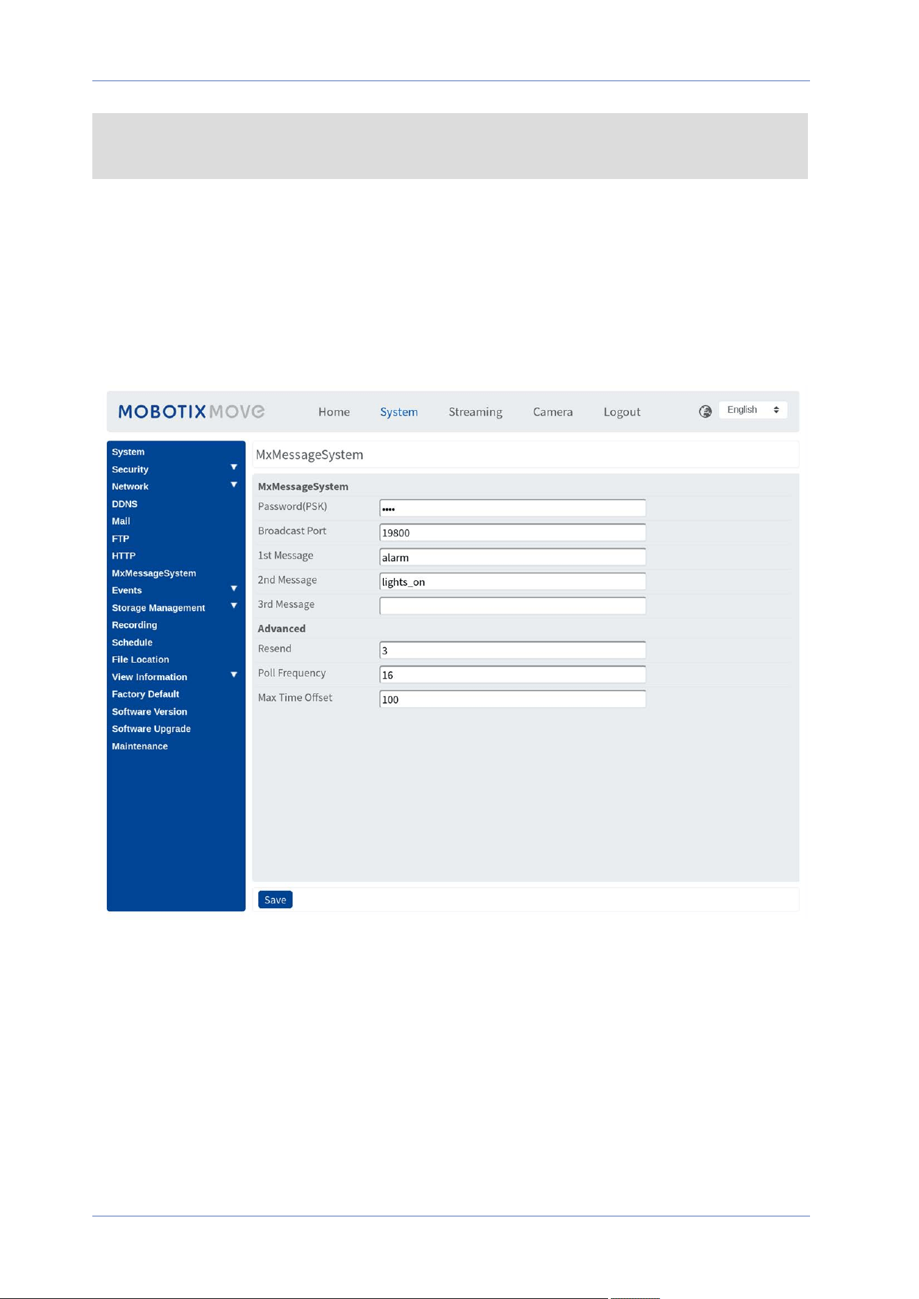
MxMessageSystem
Password (PSK): The communication is SSH encrypted. Enter your private security key.
Broadcast Port: Enter the broadcast port of the MxMessageSystem.
Messages: Enter up to three messages that can be sent to the MxMessageSystem.
Advanced
Resend: This parameter specifies how often in total the message will be resent. Many resends
increase the probability that the message is actually received, but they also create heavier network
Menu Reference
The “System” Tab
59 / 130

Menu Reference
The “System” Tab
load.
Poll frequency: This parameter specifies how often per second the messages will be sent. A higher
frequency reduces latency, but creates heavier network load.
Max. Time Offset: Maximum difference between the message timestamp and the system time. Mes-
sages with a greater difference are discarded. It is highly recommended to synchronize the system
time of all message system components using NTP (in the Date and Time dialog).
Click on Save to apply and store the settings.
NOTE! To configure events that use MxMessageSystem, open System> Events>
MxMessageSystem Event (see also Events (Alarm Settings)).
Events (Alarm Settings)
To edit the events settings, select System> Events. You will see these sections:
n
Application
n
Motion Detection
n
Network Failure Detection
n
Tampering
n
MxMessageSystem Event
n
Periodical Event
n
Manual Trigger
n
Audio Detection
n
Video Analytics
Triggered Actions (Common to All Event Types)
The following alarm actions can be triggered by the camera when it detects the corresponding event.
NOTE! Depending on the camera’s features and specific settings, some actions may not be avail-
able (e.g. FTP is only available if an FTP site has been specified).
n
Enable Alarm Output (high/low)
Select these items to enable alarm relay outputs.
n
Send Alarm Message by FTP/E-Mail
The administrator can select whether to send an alarm message by FTP and/or E-mail when
audio is detected.
60 / 130

n
Upload Image by FTP
Select this item and the administrator can assign an FTP site and configure various para-
meters. When audio is detected, event images will be uploaded to the appointed FTP site.
Note that to implement this function, one of the streaming MUST be set as MJPEG; otherwise,
this function will be grayed out and cannot be accessed.
The Pre-trigger buffer function allows users to check what happened to cause the trigger.
The Pre-trigger buffer frame rate could be pre-determined. On the other hand, Post-trigger
buffer is for users to upload certain amount of images after audio event occurs.
NOTE! The Pre-trigger buffer generally ranges from 1 to 20 frames. However, the range
will change accordingly if the frame rate of MJPEG on Streaming> Video Configuration is
6 or lower.
Check the box Continue image upload to upload the triggered images during certain time or
keep uploading until the trigger is off. Select Upload for __sec and enter the duration in the
blank. The images of the duration will be uploaded to FTP when the audio event occurs. The
setting range is from 1 to 99999 sec. Select Upload while the trigger is active to make the
images keep being uploaded to FTP during the trigger active until the event stops. Set the
Image frequency as the upload frame rate. The setting range is from 1 to 15 frames per
second.
NOTE! Make sure FTP configuration has been completed. Refer to section FTP for further
details.
Menu Reference
The “System” Tab
61 / 130

Menu Reference
The “System” Tab
n
Upload Image by E-Mail
Select this item and the administrator can assign an E-mail address and configure various para-
meters. When audio is detected, event images will be sent to the appointed E-mail address.
Note that to implement this function, one of the streaming MUST be set as MJPEG; otherwise,
this function will be grayed out and cannot be accessed.
The Pre-trigger buffer function allows users to check what happened to cause the trigger. The
Pre-trigger buffer frame rate could be pre-determined. On the other hand, Post-trigger buf-
fer is for users to upload certain amount of images after the audio event occurs.
NOTE! The Pre-trigger buffer generally ranges from 1 to 20 frames. However, the range will
change accordingly if the frame rate of MJPEG on Streaming> Video Configuration is 6 or
lower.
Check the box Continue image upload to upload the triggered images during certain time or
keep uploading until the trigger is off. Select Upload for __sec and enter the duration in the
blank. The images of the duration will be uploading by E-mail when the audio event occurs.
The setting range is from 1 to 99999 sec. Select Upload while the trigger is active to make
the images keep being uploaded to E-mail during the trigger active until the event stops. Set
the Image frequency as the upload frame rate. The setting range is from 1 to 15 frames per
second.
NOTE! Make sure SMTP configuration has been completed. Refer to section Mail for further
details.
62 / 130

n
Upload Image to SD Card
Select this item, and then the images will be uploaded to the SD card periodically. Note that
to implement this function, one of the streaming MUST be set as MJPEG; otherwise, this func-
tion will be grayed out and cannot be accessed.
The Pre-trigger buffer function can define how many images to be uploaded before the
triggered moment. The Post-trigger buffer function can define how many images to be
uploaded after the triggered moment.
NOTE! The Pre-trigger buffer generally ranges from 1 to 20 frames. However, the range
will change accordingly if the frame rate of MJPEG on Streaming> Video Configuration is
6 or lower.
NOTE! Before implementing Upload Image to SD Card, please make sure that the SD Card
is properly detected and installed. Refer to Storage Management> SD Card> Device
Information for further details.
Send message by MxMessageSystem
Check this item and select a message to be sent to the MxMessageSystem accordingly. If
required, add custom JSON parameters to the message.
n
Send HTTP Notification
Check this item, select the destination HTTP address, and specify the parameters for event
notifications by Audio Detection triggered. When an alarm is triggered, the notification can
be sent to the specified HTTP server.
For instance, if the custom parameter is set as “action=1&group=2”, and the HTTP server
name is “http://192.168.0.1/admin.php”, the notification will be sent to HTTP server as
“http://192.168.0.1/admin.php? action=1&group=2” when alarm is triggered.
Send message by MxMessageSystem
Check this item and select a message to be sent to the MxMessageSystem accordingly. If
required, add custom JSON parameters to the message.
Menu Reference
The “System” Tab
63 / 130

Menu Reference
The “System” Tab
n
Record Video Clip
Check this item and select a video recording storage type, SD Card or NAS (Network-Attached
Storage>. The Audio Detection recording will be stored in microSD/SD card or the NAS when
audio is detected.
The Pre-trigger buffer recording function allows users to check what happened to cause the
trigger. The pre-trigger buffer time range is from 1 to 3 sec. Select Upload for __ sec to set the
recording duration after audio is triggered. The setting range is from 1 to 99999 sec. Select
Upload while the trigger is active to record the triggered video until the trigger is off.
NOTE! Please make sure the local recording (with microSD/SD card) or the remote recording
(with NAS) is activated so that this function can be implemented. Refer to section Recording
for further details.
File Name
Enter a file name in the blank, e.g. image.jpg. The uploaded image’s file name format can be set in
this section. Please select the one that meets the requirements.
n
Add date/time suffix
File name: imageYYMMDD_HHNNSS_XX.jpg
Y: Year, M: Month, D: Day
H: Hour, N: Minute, S: Second
X: Sequence Number
n
Add sequence number suffix (no maximum value)
File name: imageXXXXXXX.jpg
X: Sequence Number
n
Add sequence number suffix up to # and then start over
File Name: imageXX.jpg
X: Sequence Number
NOTE! The file name suffix will end at the number being set. For example, if the setting is up
to “10”, the file name will start from 00, end at 10, and then start all over again.
n
Overwrite
The original image in the FTP site will be overwritten by the new uploaded file with a static file
name.
Click on Save to apply and store the settings.
64 / 130

Application
To edit the application settings, select System> Events> Application.
The camera supports one alarm input and one relay output for cooperation with alarm system to
catch event images. Refer to alarm pin definition below to connect alarm devices to the camera if
needed.
Alarm Switch
The default setting for the Alarm Switch function is Off. Enable the function by selecting On. You
can also activate the function according to the schedule previously set in the Schedule setting
page. Select By schedule and click Please select… to choose the desired schedule from the drop-
down menu.
Alarm Type
Select an alarm type, Normal close or Normal open, that corresponds with the alarm application.
Triggered Action
See the section Triggered Actions (Common to All Event Types), p. 60 for information about the vari-
ous actions that can be triggered.
Click on Save to apply and store the settings.
Motion Detection
To edit the motion detection settings, select System> Events> Motion Detection.
Motion Detection function allows the camera to detect suspicious motion and trigger alarms by
comparing sampling pixels in the detection area of two consecutive live images. When motion
volume in the detection area reaches/exceeds the determined sensitivity threshold value, the alarm
will be triggered.
The function supports up to 4 sets of Motion Detection Settings. Settings can be chosen from the
Motion Detection drop-down menu.
Motion Detection
By default, motion detection is Off. Select On to enable this feature.
You can also activate the function according to the schedule previously set in the Schedule setting
page. Select By schedule and click Please select… to choose the desired schedule from the drop-
down menu.
Menu Reference
The “System” Tab
65 / 130
Menu Reference
The “System” Tab
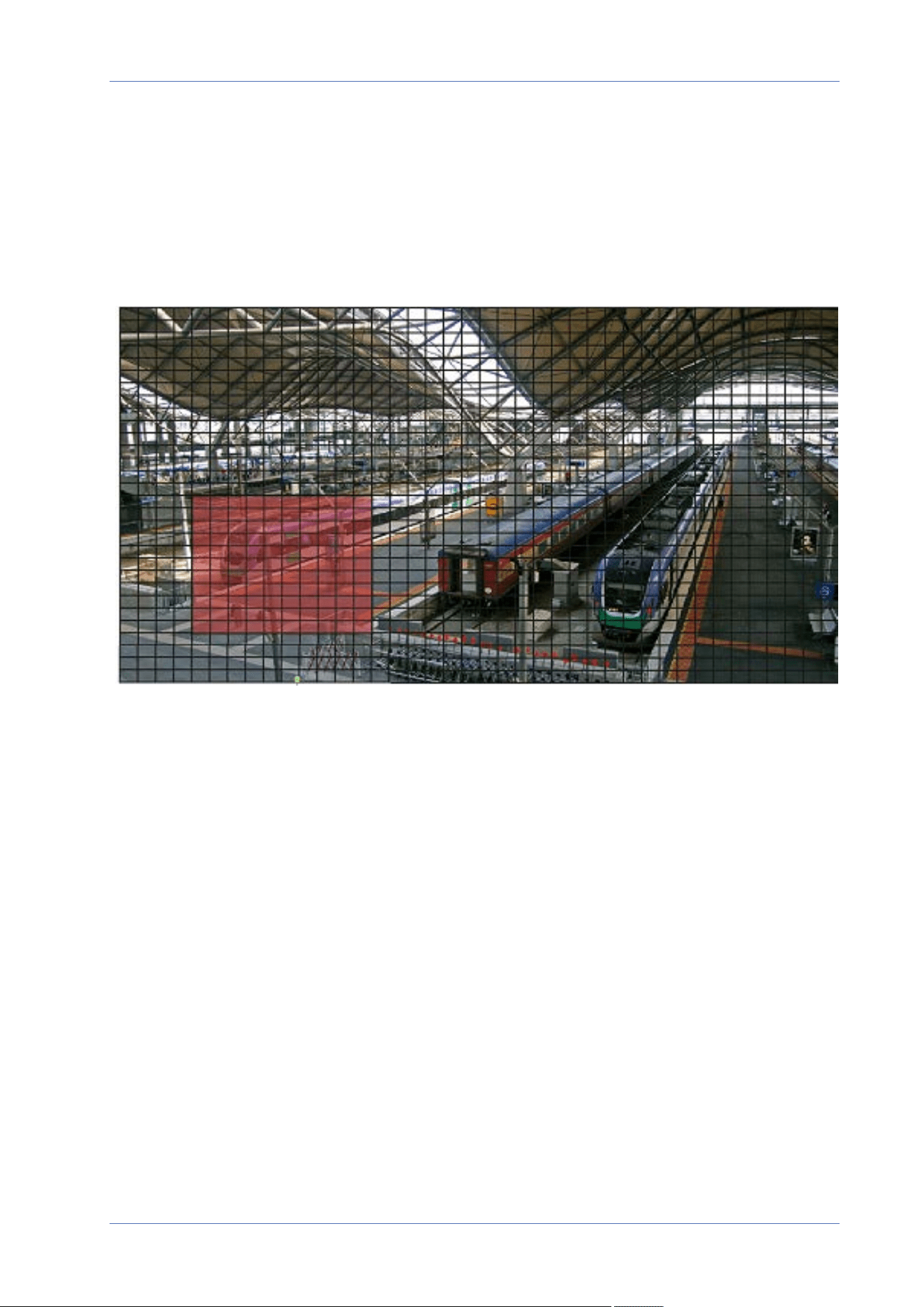
Motion Region Paint
The camera divides the detection area into 1200 (40x30) detection grids; you can draw the motion
detection region using the paintbrush.
Check the box Enable brush and select the brush size, 1x1, 3x3 or 5x5. Then, left click and drag the
mouse cursor to draw the preferred detection region. To erase the drawn detection region, left click
and drag the mouse cursor on the colored grids.
Motion Detection Setting
Users could adjust various parameters of Motion Detection in this section.
66 / 130
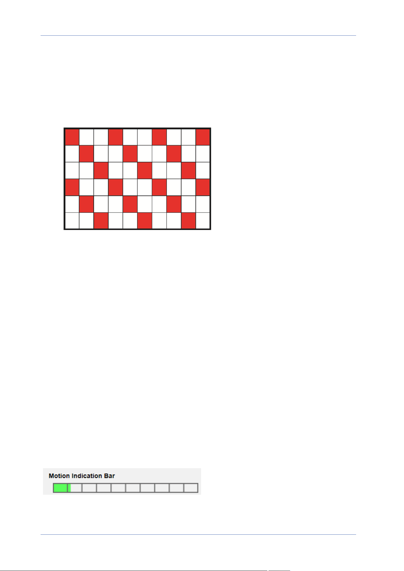
n
Sampling pixel interval [1-10]:
This item is used to examine the differences between two frames. You can configure the inter-
val of sampling pixel. The default value is 1. For instance, if users set the interval as 3, IP cam-
era system will take one sampling pixel from every 3 pixels of each row and each column in
detection area (refer to the figure below). The alarm will be triggered when differences are
detected.
n
Detection level [1-100]:
You can configure detection level for each sampling pixel. Detection level is how much the
camera can accept the differences between two sampling pixels. The smaller the value is, the
more minor motions it detects. The default level is 10.
n
Sensitivity level [1-100]:
The default level is 80, which means if 20% or more sampling pixels are detected differently,
system will detect motion. The bigger the value, the more sensitive it is. Meanwhile, when the
value is bigger, the red horizontal line in the motion indication window will be lower accord-
ingly.
n
Time interval (sec) [0-7200]:
The value is the interval between each detected motion. The default interval is 10.
Motion Indication Bar
When Motion Detection function is activated and the motion is detected, the signals will be dis-
played on the motion indication bar. The motion indication bar will go green or red when there is
any motion occurrence in the detection region.
Green suggests the occurring motion is detected and does not exceed the threshold of detection
level and sensitivity level. No alarms will be triggered.
Menu Reference
The “System” Tab
67 / 130
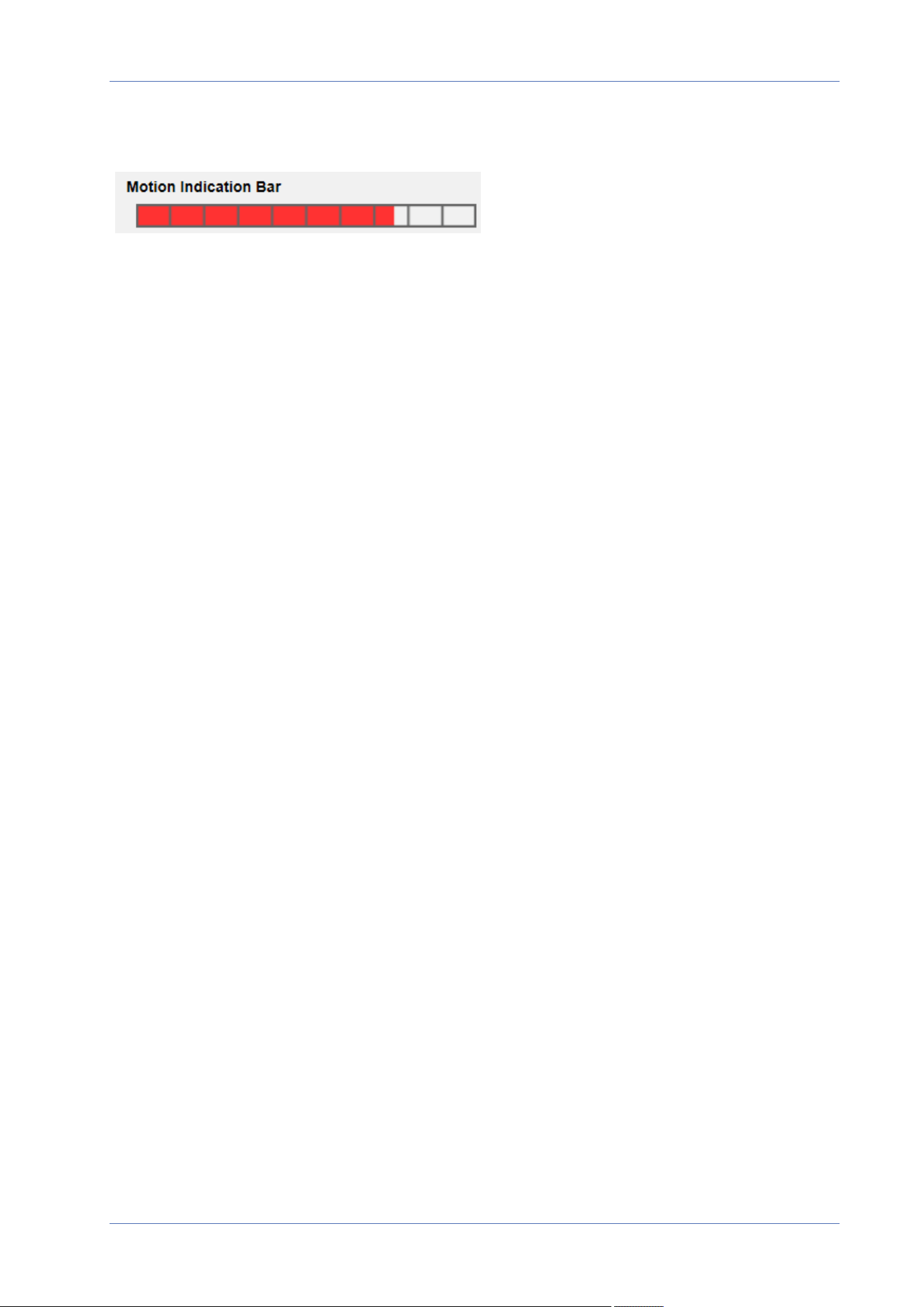
Menu Reference
The “System” Tab
Red suggests the ongoing motion exceeds the threshold of detection level and sensitivity level. The
alarm will be triggered.
Triggered Action
See the section Triggered Actions (Common to All Event Types), p. 60 for information about the vari-
ous actions that can be triggered.
Click on Save to apply and store the settings.
Network Failure Detection
To edit the network failure detection settings, select System> Events> Network Failure Detection.
Network Failure Detection allows the camera to ping another IP device (e.g. NVR, VSS, Video Server,
etc.) within the network periodically and generates some actions in case of network failure occurs,
for instance, a Video Server is somehow disconnected.
Being capable of implementing local recording (through microSD/SD card) or remote recording (via
NAS) when network failure happens, the camera can be a backup recording device for the sur-
veillance system.
Detection Switch
The default setting for the Detection Switch function is Off. Enable the function by selecting On. You
can also activate the function according to the schedule time that is previously set in the Schedule
setting page. Select By schedule and click Please select… to choose the desired schedule from the
drop-down menu.
Detection Type
Input the IP device address and the period of ping time to ping. The camera will ping the IP device
every N minute(s). If it fails for up to three times, the alarm will be triggered. The ping time setting
range is from 1 to 99 min.
Triggered Action
See the section Triggered Actions (Common to All Event Types), p. 60 for information about the vari-
ous actions that can be triggered.
Click on Save to apply and store the settings.
MxMessageSystem Event
To edit the MxMessageSystem Event settings, select System> Events> MxMessageSystem Event.
68 / 130

MxMessageSystem Alarm function can trigger an action if a notification by the MxMessageSystem is
received
MxMessageSystem Alarm
The default setting for the MxMessageSystem Alarm function is Off. Enable the function by selecting
On. You can also activate the function according to the schedule previously set in the Schedule set-
ting page. Select By schedule and click Please select… to choose the desired schedule from the
drop-down menu.
MxMessageSystem Setting
n
Message Path/Name: Enter the message path of the MxMessage which should trigger an
action. Minimum Tampering Duration is the time for video analysis to determine whether
camera tampering has occurred. Minimum Duration could also be interpreted as defining the
Tampering threshold; longer duration represents higher threshold. Settable Tampering Dur-
ation time range is from 10 to 3600 sec. The Default value is 20 sec.
n
Action Duration: Set a time period in seconds after which a triggered action such as video
recording is to be ended.
Triggered Action
See the section Triggered Actions (Common to All Event Types), p. 60 for information about the vari-
ous actions that can be triggered.
Click on Save to apply and store the settings.
Periodical Event
To edit the periodical event settings, select System> Events> Periodical Event.
With Periodical Event setting, you can set the camera to upload images periodically to an FTP site
or an E-mail address. For example, if the time interval is set to 60 seconds, the camera will upload
images to the FTP site or the E-mail address every 60 seconds. The images to be uploaded are the
images before and after the triggered moment. You can define how many images to be uploaded in
the Triggered Action section of this setting page.
Periodical Event
The default setting for the Periodical Event function is Off. Enable the function by selecting On.
Time Interval
The default value of the time interval is 60 seconds. The setting range of the time interval is from 60
to 3600 seconds.
Menu Reference
The “System” Tab
69 / 130

Menu Reference
The “System” Tab
Triggered Action
See the section Triggered Actions (Common to All Event Types), p. 60 for information about the vari-
ous actions that can be triggered.
Click on Save to apply and store the settings.
Manual Trigger
To edit the manual trigger settings, select System> Events> Manual Trigger.
With Manual Trigger setting, the current image(s) or video can be uploaded to the appointed des-
tination, such as an FTP site or an E-mail address. The administrator can specify the triggered actions
that will take when the users switch the Manual Trigger button to ON. All options are listed as fol-
lows.
Manual Trigger
The default setting for the Manual Trigger function is Off. Enable the function by selecting On. After
the Manual Trigger function is enabled, click the Manual Trigger button on the Home page to start
uploading data. Click again to stop uploading.
Triggered Action
See the section Triggered Actions (Common to All Event Types), p. 60 for information about the vari-
ous actions that can be triggered.
Click on Save to apply and store the settings.
Audio Detection
To edit the audio detection settings, select System> Events> Audio Detection.
Audio Detection function allows the camera to detect audio and trigger alarms when audio volume in
the detected area reaches or exceeds the determined sensitivity threshold value.
NOTE! Audio Detection function is only available for models equipped with Audio I/O function.
Audio Detection
In Audio Detection Setting, the default setting for the Audio Detection function is Off. Enable the func-
tion by selecting On.
Audio Detection Setting
Users could adjust various parameters of Audio Detection in this section.
70 / 130

n
Detection level [1-100]:
The item is to set detection level for each sampling volume; the smaller the value, the more
sensitive it is. The default level is 10.
n
Time interval (sec) [0-7200]:
The value is the interval between each detected audio. The default interval is 10.
Triggered Action
See the section Triggered Actions (Common to All Event Types), p. 60 for information about the vari-
ous actions that can be triggered.
Click on Save to apply and store the settings.
Menu Reference
The “System” Tab
71 / 130
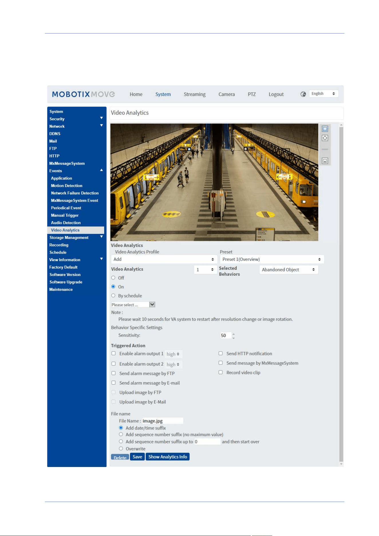
Menu Reference
The “System” Tab
Video Analytics
To edit the video analytics settings, select System> Events> Video Analytics.
72 / 130

Video Analytics Profile
You can create Video Analytics (VA) profiles to direct the camera to different preset positions and
then execute the specified video analytics “behaviors” (max. two can be used at one position).
NOTE! Before you can store additional profiles beside the Default profile, you need to set preset
positions as outlined in Preset, p. 108. You can set up many different presets; make sure you
name them properly (“Overview”, “StairsLeft”, “StairsRight”, ...) so you can identify them easier in
this dialog.
Setting up Different Video Analytics Profiles
A video analytics profile combines a preset position with a video analytics function. You can either
select a profile manually or by using automated position sequences (see Sequence, p. 110).
1. Click on the Video Analytics Profiles dropdown and select Add.
2. Select a preset position, such as Preset1(Overview).
3. Under Selected Behavior, select the VA function you want to use (e.g. Abandoned Object).
4. Set the Video Analytics option to On or By schedule and select a schedule (see Schedule, p. 82
on how to define one).
5. Select the settings for the chosen behavior in the Behavior-Specific Settings section (see Video
Analytics Behaviors, p. 74).
6. Select the action you want to execute in case the camera detects an event in the Triggered
Action section.
7. Click on Save at the bottom of the dialog to save this profile (in this case, it gets the name of
the selected preset, e.g. Preset1).
When you select a profile for testing in this dialog, the camera will move to the corresponding pos-
ition and execute the selected behavior. When selecting one of the preset positions for which you
defined a Video Analytics profile in the Home screen, the camera will execute the assigned VA func-
tion.
NOTE! After moving to a new position, the camera needs about 10 seconds before the selected VA
function can be executed properly (adjustment of focus, exposure, etc.).
Editing a Video Analytics Profile
1. Select the profile you want to edit in Video Analytics Profile.
2. Edit the profile as desired.
3. Click on Save at the bottom of the dialog.
Menu Reference
The “System” Tab
73 / 130

Menu Reference
The “System” Tab
Deleting a Video Analytics Profile
1. Select the profile you want to delete in Video Analytics Profile.
2. Click on Delete at the bottom of the dialog.
Combining a Sequence With Video Analytics Profiles
A sequence line is set of preset positions to which the camera will move automatically one after the
other. To combine such a sequence line with specific video analytics functions for each position, pro-
ceed as follows.
1. Define preset positions and save profiles as outlined in Video Analytics Profile, p. 73.
2.
Define a Sequence line in PTZ> Sequence, p. 110 by selecting the preset positions you want to
use (for this example, we will set up sequence line #1).
NOTE! Set the Dwell Time for every preset to at least 15 seconds so the camera has enough
time to adjust the focus, set the exposure, etc. and to execute the video analytics function
before moving to the next position.
3.
Click on Home in the main menu, open the control panel by clicking on and from the
SEQUENCE dropdown, select 1.
The camera will now move to the preset positions defined in this sequence line (it executes a
“sequence run”). If you defined a Video Analytics profile for a preset position, the camera will execute
the selected function at that position.
To stop the sequence run, select a preset position in the PRESET dropdown or move the camera pos-
ition using the mouse (click and drag in the image) or click on one of the arrow buttons in the PTZ
control panel.
Video Analytics Behaviors
Every profile allows defining two different behaviors from the Selected Behaviors dropdown. For
example:
n
Set Video Analytics to 1.
n
From Selected Behaviors, select Face Detection.
n
Under Behavior-Specific Settings, configure the settings for the selected behavior option (in
this case, you could activate the Face and Gender checkboxes).
n
Click on Save to apply and store the settings.
n
Set Video Analytics to 2.
n
From Selected Behaviors, select Abandoned Object.
NOTE! You cannot select the same a behavior already selected for Video Analytics #1.
74 / 130
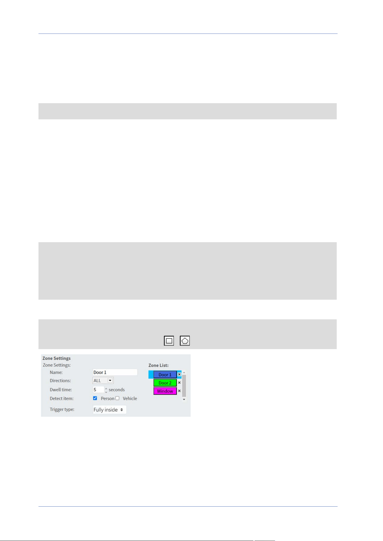
n
Under Behavior-Specific Settings, configure the settings for the selected behavior option (in
this case, you could change the Sensitivity).
n
Click on Save to apply and store the settings.
Auto Tracking
NOTE! This section is only available for the Intrusion Detection behavior.
The Auto Tracking feature of the MOBOTIX MOVE 2MP Low-Light Video Analytics Speed Dome will
follow objects that enter the live image of the camera.
n
Enable auto tracking: Activates the auto tracking feature.
n
Resume PTZ status after tracking: Returns to the original position after auto tracking has
stopped.
n
Duration
n
Always: No limit on auto tracking.
n
Others: Sets a time limit to auto tracking.
n
Click on Save to apply and store the settings.
NOTE!
Objects in the image need to have at least this size for autotracking to work properly.
n
Persons: 50 x 135 pixels (1080p)
n
Vehicles: 70 x 70 pixels (1080p)
Zone Settings
NOTE! This section is only available for the Intrusion Detection behavior and if you have defined
at least one zone in the image (using the / buttons).
n
The active zone in the Zone List has a blue background.
n
The defined zones get default names (“Zone 1”, “Zone 2”, ...). To rename a zone, click on a
zone and enter a different name (in this case, “Door 1”, Door 2”, and “Window”).
n
To delete a zone, click on the trailing “x” after the zone name in the list.
n
Directions: Select one direction or ALL to trigger based on direction of movement.
Menu Reference
The “System” Tab
75 / 130
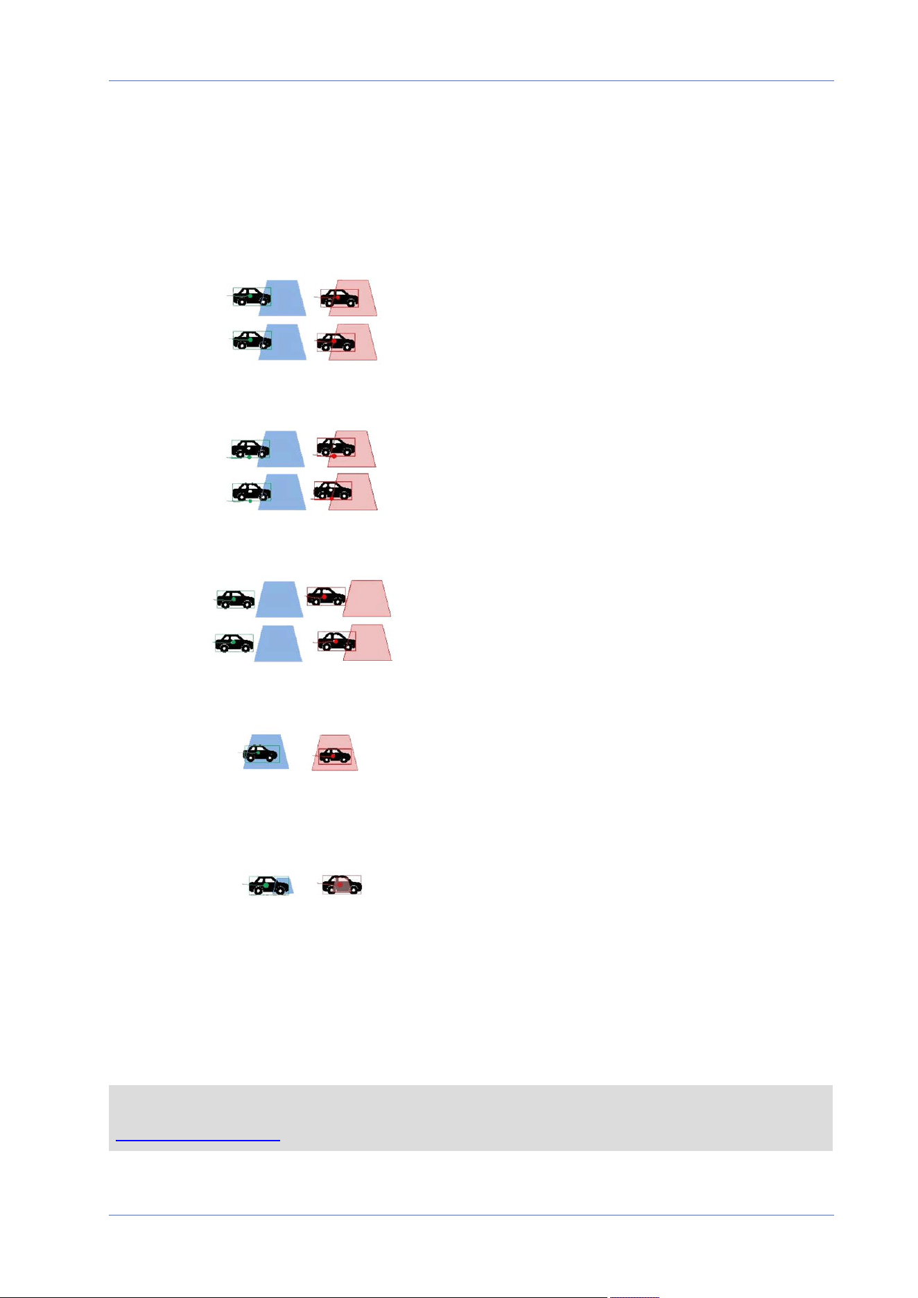
Menu Reference
The “System” Tab
n
Dwell time: Enter the minimum number of seconds for the object to stay within the zone to
trigger.
n
Detect item: Allows detecting only persons or vehicles, or both.
n
Trigger Type: Provides additional options on how an object enters the zone.
n
Center: Triggers if the center of the object bounding box enters the zone.
n
Bottom center: Triggers if the bottom center of the object bounding box enters the zone.
n
Edge: Triggers if an edge of the object bounding box enters the zone.
n
Fully inside: Triggers if the object bounding box is fully inside the zone (e.g. door frame).
n
Fully cover: Triggers if the object bounding box covers the entire zone (e.g. small area in
a passageway or gate).
n
Click on Save to apply and store the settings.
Show Analytics Info
Click on Show Analytics Info to open a separate window that contains the event stream of the cam-
era. This will allow you to monitor the events that are detected by the currently defined settings (e.g.
for testing the setup).
NOTE! For more information on how to operate the Video Analytics settings, please refer to the
Video Analytics Manual.
76 / 130

Triggered Action
See the section Triggered Actions (Common to All Event Types), p. 60 for information about the vari-
ous actions that can be triggered.
Click on Save to apply and store the settings.
Storage Management
To edit the storage management settings, select System> Storage Management.
Click on Storage Management, there will be a drop-down menu with tabs including SD Card and
Network Share.
SD Card
To edit the settings for the SD card, select System> Storage Management> SD Card.
You can implement local recording to the microSD/SDHC/SDXC card with up to 1TB capacity.
This page shows the capacity information of the storage medium and a recording list with all the
recording files saved on the memory card. You can also format the storage medium and implement
automatic recording cleanup through the setting page.
To implement recording on a storage medium, please go to the Recording page (see Recording, p.
80).
NOTE! Please format the storage medium when using it for the first time. Formatting will also be
required when a storage medium is being used on one camera and later transferred to another
camera with different software platform.
It is not recommended to record on microSD/SD cards for 24/7 continuously, as it may not be able
to support long term continuous data read/write. Please contact the manufacturer of the
microSD/SD card for information regarding reliability and life expectancy.
Device Information
After the storage medium is inserted into the camera, the card information such as memory capa-
city and status will be shown at Device Information.
Recording Source
Select a video stream to set as the recording source. The default format of the video stream is
Stream 1. Select a preferred stream from the drop-down list.
Click on Save to apply and store the settings.
Recording Filename Format
Menu Reference
The “System” Tab
77 / 130

Menu Reference
The “System” Tab
Select a format as the recording file name format. The default recording file name format is Start
time only. Select a preferred format from the drop-down list.
Click on Save to apply and store the settings.
Device Setting
Click on Format to format the storage medium.
Two file systems are provided: vfat (default) and ext4. It is recommended to select ext4 for steady
and better performance.
Disk Cleanup Setting
Check Enable automatic disk cleanup and specify the time 1~999 day(s) or 1~142 week(s) and
storage limits 1~99% full to configure disk cleanup settings.
Click on Save to apply and store the settings.
Recording List
Enter the period in the date fields and click on Search. Select Video / JPEG, and then each video/im-
age file on the storage medium will be listed in the recording list. The maximum file size is 60 MB/per
file.
When the recording mode is set as Always (consecutive recording) and the storage medium record-
ing is also allowed to be enabled by events triggered, once events occur, the system will immediately
implement events recording to the memory card. After the recording of the events are finished, the
camera will return to the regular recording mode.
n
Remove
To remove a file, select the file first, and then click Remove button.
n
Sort
Click on Sort, and the files in the Recording list will be listed in name and date order.
The capital letter at the beginning of a name indicates the type of recording:
Initial Recording Type Initial Recording Type
A Alarm S Periodical Event
M Motion R Regular Recording
N Network Failure V Manual Trigger
T Tampering U Audio Detection
78 / 130

n
Download
To open/download a video clip/image, select the file first, then click on Download below the
Recording list. The selected file window will pop up. Click on the AVI/JPEG file to download
the file to the specified location.
Network Share (NAS)
To edit the network share settings, select System> Storage Management> Network Share.
You can store the recording videos to a network share folder, or NAS (Network-Attached Storage). A
NAS device is used for data storage and data sharing via network. This page displays the capacity
information of the network device and a recording list with all the recording files saved on the net-
work device. You can also format the NAS and implement automatic recording cleanup through the
setting page.
Device Information
When a NAS is successfully installed, the device information such as the memory capacity and
status will be shown at Device Information.
Storage Setting
The administrator can set the camera to send the alarm messages to a specific NAS site when an
alarm is triggered. Enter the network device details, which include host (the IP of the NAS), share
(the folder name of the NAS), user name, and password, in the fields.
Click on Save to apply and store the settings.
Storage Tools
Click on Format to format the NAS.
Recording Source
Select a video stream to set as the recording source. The default format of the video stream is
Stream 1. Select a preferred stream from the drop-down list.
Click on Save to apply and store the settings.
Recording Filename Format
Select a format to set as the recording file name format. The default recording file name format is
Start time only. Select a preferred format from the drop-down list
Click on Save to apply and store the settings.
Disk Cleanup Setting
Check Enable automatic disk cleanup and specify the time 1~999 day(s) or 1~142 week(s) and
storage limits 1~99% full to configure disk cleanup settings.
Menu Reference
The “System” Tab
79 / 130

Menu Reference
The “System” Tab
Click on Save to confirm the settings.
Recording List
Each video file on the Network Share will be listed in the Recording list. The maximum file size is 60
MB/per file.
When the recording mode is set as Always (consecutive recording) and the NAS recording is also
allowed to be enabled by events triggered, once events occur, the system will immediately imple-
ment events recording to NAS. After the recording of the events are finished, the camera will return
to the regular recording mode.
n
Remove
To remove a file, select the file first, and then click on Remove.
n
Sort
Click on Sort, and the files in the Recording list will be listed in name and date order.
The capital letter at the beginning of a name indicates the type of recording:
Initial Recording Type Initial Recording Type
A Alarm S Periodical Event
M Motion R Regular Recording
N Network Failure V Manual Trigger
T Tampering U Audio Detection
n
Download
To open/download a video clip, select the file first, and then click on download below the
Recording list field. The selected file window will pop up. Click on the AVI file to directly play
the video in the player or download it to a specified location.
Recording
To edit the recording settings, select System> Recording.
In the Recording setting page, you can specify the recording schedule that fits the present sur-
veillance requirement.
80 / 130
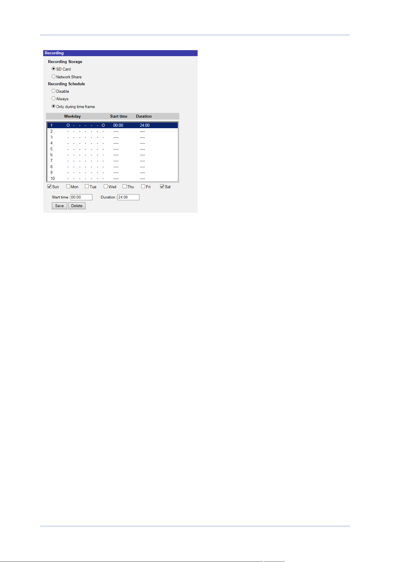
Recording Selector
Select Camera1 to Camera4 from the drop-down menu to configure the video stream from the cor-
responding camera head.
Recording Storage
Select SD Card or Network Share as recording storage.
Enable Recording Schedule
Two types of schedule mode are offered: Always and Only during time frame. You can select
Always to activate recording on a storage medium or network storage all the time. Or, select a set
of schedule from the time frame blank, check specific weekdays and setup the start time
(hour:minute) and time period (hour:minute) to activate the recording at certain time frames. The
setting range for the duration time is from 00:00 to 168:59.
Click on Save to apply and store the settings.
To delete a schedule, select one from the schedule list, and click Delete.
Disable Recording Schedule
n
Select Disable to terminate the recording function.
n
Click on Save to apply and store the settings.
Menu Reference
The “System” Tab
81 / 130
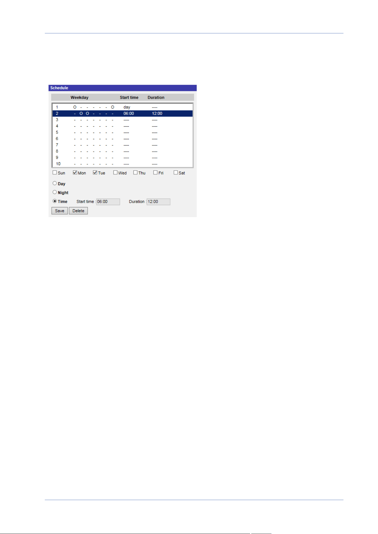
Menu Reference
The “System” Tab
Schedule
To edit the schedule settings, select System> Schedule.
Schedules Setup
1. Select a time frame from the time frame list.
2. Check the weekday boxes below to choose the specific weekdays.
3. Select a time mode, Day, Night or Time. Under Time mode, specify the start time (hour:minute)
and the time duration (hour:minute) to activate the schedule triggered features. The setting
range for the time duration is from 00:00 to 168:59.
4. Click on Save to apply and store the settings.
Alternatively, click on Delete to remove the highlighted time frame.
Time Mode
n
Day
The camera profile will be loaded when IR cut filter is on.
n
Night
The camera profile will be loaded when IR cut filter is off.
82 / 130

n
Time
This indicates the start time and the time duration for the schedule.
NOTE! Users MUST select By schedule under each feature setting page to enable the sched-
ule function.
File Location (Snapshots and Web Recording)
To edit the file location settings, select System> File Location.
You can specify a storage location on the PC or in the hard drive for the snapshots and the live
video recordings. The default setting is: C:\. Once the setting is confirmed, click on Save, and all the
snapshots and the web recordings will be saved in the designate location.
NOTE! Make sure the selected file path contains valid characters such as letters and numbers.
View Information
To edit the view information settings, select System> View Information.
Click on View Information, there will be a drop-down menu with tabs including Log File, User
Information, and Parameters.
Log File
To edit the log file settings, select System> View Information> Log File.
Click on the tab to view the system log file. The camera keeps a record of the system’s behavior and
information related to the camera. These log data can be exported for future use. Click generate
syslog and the Save File As dialog window will pop up. The default file name is named after the
model name and the MAC address as “Model Name-MAC-log.tgz”. Select the file destination and
click Save to export the log data.
NOTE! “Save File As” dialog window may not show up immediately for the camera needs some
time to process the log data.
User Information
To edit the user information settings, select System> View Information> User Information.
Menu Reference
The “System” Tab
83 / 130

Menu Reference
The “System” Tab
The administrator can view the privileges of each user (refer to Security, p. 42). User lines follow this
syntax:
<User name>: <I/O access>:<camera control>:<talk>:<listen>
Example: <main-entrance>: 1:1:0:1
Values for <I/O access>, <camera control>, <talk>, and <listen>:
n
1: function allowed
n
0: function blocked
NOTE! The talk and listen privileges will be set regardless of the audio capabilities of the camera.
Parameters
To edit the parameters settings, select System> View Information> Parameter.
Click on this item to view the parameter settings of the entire system, such as Camera Settings, Mask
Information and Network Information.
Factory Default
To edit the factory default settings, select System> Factory Default.
You can follow the instructions on this page to reset the camera to factory default settings if needed.
Full Restore
Click on Full Restore to recall the factory default settings. The camera system will restart in 30
seconds. The IP address will be restored to default. After the camera system is restarted, reconnect
the camera using the default IP address. The default IP address is 192.168.0.250.
Partial Restore
Click on Partial Restore to recall the factory default settings (excluding network settings). The cam-
era system will restart in 30 seconds. Refresh the browser page after the camera system is restarted.
NOTE! The IP address will not be restored to default.
Reboot
Click on Reboot and the camera system will restart without changing the current settings. Refresh
the browser page after the camera system is restarted.
84 / 130

Software Version
To see the software version, select System> Software Version.
Software Upgrade
To edit the software upgrade settings, select System> Software Upgrade.
NOTE! Make sure the upgrade software file is available before carrying out software upgrade.
The procedure of software upgrade is as below.
1. Click on Browse and locate the upgrade file, for example, “ulmage_userland”.
NOTE! Do not change the name of the upgrade file, or the system will fail to find the file.
2. Pick a file type from the drop-down menu. In this case, select “ulmage+userland.img”.
3. Click on Upgrade. Then the system will prepare to start the software upgrade. Subsequently, an
upgrade status bar will be displayed on the page to show the current upgrade process. After the
upgrade process is finished, the viewer will return to the Home page.
4. Close the video browser.
5. Click on Start and activate the Control Panel. In the appeared window, double-click on Add or
Remove Programs. A window with the Currently install programs list will pop up. In the list,
select the viewer and click on Remove to uninstall the existing progam.
6. Open a new web browser and re-login the camera. Users will be prompted to download the
viewer. Once the viewer is downloaded and installed, the live video will be available.
Maintenance
To edit the maintenance settings, select System> Maintenance.
You can export configuration files to a specified location and retrieve data by uploading the con-
figuration file to the camera.
Export Files
You can save the system settings by exporting a configuration file (.bin) to a specified location for
future use. Click on Export, and the popup File Download window will come out. Click on Save and
specify a desired location for saving the configuration file.
Menu Reference
The “System” Tab
85 / 130

Menu Reference
The “System” Tab
Upload Files
To upload a configuration file to the camera, click on Browse to select the configuration file and then
click on Upload for uploading.
86 / 130
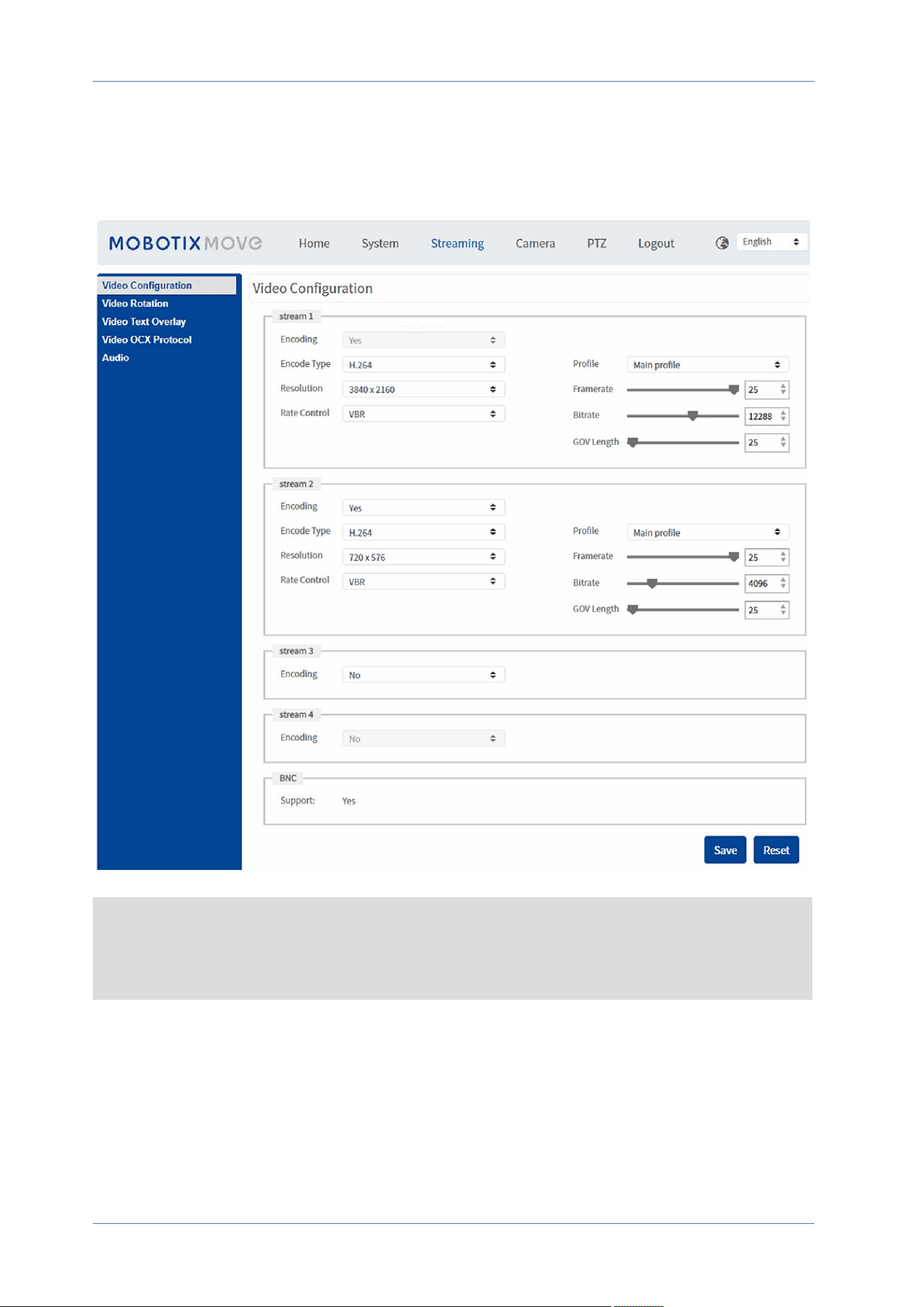
The “Streaming” Tab
To edit the video configuration settings, select Streaming> Video Configuration.
NOTE!
n
Only the administrator can access the Streaming configuration page.
n
The preset resolution and other settings will vary depending on the current camera model.
Menu Reference
The “Streaming” Tab
87 / 130

Menu Reference
The “Streaming” Tab
Video Configuration
To edit the video configuration, select Streaming> Video Configuration.
Encoding
For stream2 to stream4, select Yes to enable a stream and No to disable it.
Encode Type
The available video resolution formats include H.265, H.264, and MJPEG. You can select the preferred
encode type from the drop-down menu.
Resolution
The following table lists the default resolution of the camera.
IP Camera Model Default Resolution
2MP Low-Light Video Analytics Speed
Dome
Mx-SD2A-230-LL-VA
WDR on/off H.265/H.264: 1920 × 1080 (30fps) +
MJPEG: 1080 × 720 (30fps)
Frame Rate
Video frame rate is for setting the frames per second (fps) if necessary.
The default setting of Stream 1 is 30fps (NTSC) or 25fps (PAL). The maximum frame rate range of
each stream will change according to the selected video resolution.
NOTE!
n
Low frame rate will decrease video smoothness.
n
Please make sure the higher compression ratio is supported by the system before setup.
Profile
You can set H.265/H.264 Profile to High Profile or Main Profile according to its compression needs.
With the same bit rate, the higher the compression ratio, the better the image quality is. The default
setting is Main Profile.
88 / 130

Rate Control
The following H.265/H.264 bit rate modes are supported:
n
CBR (Constant Bit Rate)
The video bitrate of the video stream will be fixed and consistent to maintain the bandwidth.
n
VBR (Variable Bit Rate)
The video bitrate of the video stream varies according to the activity of the monitoring envir-
onment to achieve better image quality.
n
LBR (Low Bit Rate)
LBR keeps low bitrate and ensures superior image quality. To implement LBR control, setup
the compression level and dynamic GOV for each streaming accordingly beforehand.
n
Compression
Based on the current application area and streaming bit rate, select the most suitable
compression level, high/mid/low.
n
Set High, and bit rate will vastly be reduced; however, image quality may be
degraded at the same time.
n
Set Low, and bit rate will stably keep low while image quality remains high.
n
Dynamic GOV
According to the amount of motion in the application area, the GOV length of the video
will be adjusted dynamically to reduce more bit rate, especially for scenes with minor
changes. The length of Dynamic GOV is from GOV Length to Max. GOV (4094).
n
Select Enabled and set Max. GOV. Then click on Save to activate the setting.
n
If there is small or zero activity in the scene, set Max. GOV larger, the GOV length
will be longer, resulting in lower bit rate and bandwidth.
n
If there are constant dynamic changes in the scene, it is suggested just adjust
GOV Length and disable Dynamic GOV.
Click on Save to apply and store the settings.
Bit Rate
The default setting of the H.265/H.264 bit rate for Stream 1/2 is 4096 kbit/s; for Stream 3/4 is 2048
kbit/s. The setting range is from 64 to 20480 kbit/s, and the total bit rate should not exceed
26624kbit/s.
Menu Reference
The “Streaming” Tab
89 / 130

Menu Reference
The “Streaming” Tab
GOV Length
You can set the GOV length to determine the frame structure (I-frames and P-frames) in a video
stream to save bandwidth. Less bandwidth is needed if the GOV length is set to a high value.
However, the shorter the GOV length, the better the video quality is.
The default setting for the available streams is 50. The setting range of the GOV length is from 1 to
4094.
Q (Quality) Factor (MJPEG Only)
The default setting of MJPEG Q factor is 35; the setting range is from 1 to 70.
BNC Support
The BNC Support: (Yes/No) item indicates whether the current resolution combination supports
BNC output.
If users want to check the camera view via connecting a BNC monitor, please configure the
stream/resolution settings as below:
Stream Resolution
Single Stream All available resolutions of Stream 1
Dual Stream (1) Stream 1 = Stream 2 or
(2) Stream 2 ≦ D1
Triple Stream Stream 1 = Stream 2 = Stream 3
Quad Stream Stream 1 = Stream 2 = Stream 3 = Stream 4
Video Rotation
Rotate Function
You can change video display type if necessary. Selectable video rotate types include Mirror video
and 90/180/270 degree clockwise rotate. Refer to the following descriptions for the different video
rotate type.
n
Mirror
Select yes from the drop-down menu, and the image will be mirrored horizontally.
90 / 130

n
Rotate Type
You can choose 0, 90, 180, or 270 degrees from the drop-down menu to rotate the image.
Click on Save to apply and store the settings.
Video Text Overlay
You can select the items to display data including date & time/text string/subtitle/image on the live
video pane.
Overlay Type
You can select at most three items out of four options including date & time/text string/sub-
title/image to display on the live video pane.
n
Include Date & Time
Check the box to enable date & time display on the Live Video Pane and a Video Text Overlay
Window will show up. Move the mouse cursor to the center of the window then click and drag
the window to preferred display position. You can choose to display date, time, or date &
time from the drop-down menu, and decide the string align position (left/right).
n
Include Text String
Check the box to enable text string display on the Live Video Pane and a Video Text Overlay
Window will show up. Move the mouse cursor to the center of the window then click and drag
the window to preferred display position. Type the text to display in the entry field and
decide the string align position (left/right). The maximum length of the text string is 15 alpha-
numeric characters.
n
Include Subtitle
Check the box to enable subtitle display on the Live Video Pane and a Video Text Overlay Win-
dow will show up. Move the mouse cursor to the center of the window then click and drag
the window to preferred display position. Type the text to display in the entry field and
decide the string align position (left/right). You can set at most 5 subtitles, and the maximum
length of each subtitle is 16 alphanumeric characters.
n
Include Image
Check the box to enable image display on the Live Video Pane and a Video Text Overlay Win-
dow will show up. Move the mouse cursor to the center of the window, click and drag the win-
dow to preferred display position, and then decide the string align position (left/right).
Click on Set to confirm the setting.
Menu Reference
The “Streaming” Tab
91 / 130

Menu Reference
The “Streaming” Tab
Text Overlay Setting
You can choose the Text Overlay Color (black, white, yellow, red, green, blue, cyan, or magenta) and
Text Overlay Size (small, medium, or large) of the display date & time/text string/subtitle.
Click on Set to confirm the setting.
Image Overlay Setting
Users must save the image as a 8-bit BMP file; the length should be the multiple of 32, and the width
should be the multiple of 4. The maximum resolution of the image should not exceed 32768 pixels.
Click on Set and Upload to confirm the setting.
Video OCX Protocol
To edit the video OCX protocol settings, select Streaming> Video OCX Protocol.
In the Video OCX protocol setting page, the administrator can select RTP over UDP, RTP over RTSP
(TCP), RTSP over HTTP or MJPEG over HTTP, for streaming media over the network. In the case of
multicast networking, you can select the Multicast mode. Click on Save to confirm the setting.
Video OCX protocol setting options include:
n
RTP over UDP/RTP over RTSP(TCP) / RTSP over HTTP/MJPEG over HTTP
n
Multicast Mode
Enter all required data, including Multicast Stream 1~4 Video Address, Multicast Port and
Multicast TTL into each blank.
Click on Save to apply and store the settings.
Audio (Audio Mode and Bit Rate Settings)
To edit the audio mode settings, select Streaming> Audio.
In this page, the administrator can adjust the sound transmission mode, the audio gain levels and
the audio bit rate. Setting for enabling sound recording to the microSD/SD card is also available.
92 / 130

Transmission Mode
n
Full-duplex (Talk and Listen simultaneously)
In the Full-duplex mode, the local and remote sites can communicate with each other sim-
ultaneously, i.e. both sites can speak and listen to the other side at the same time.
n
Half-duplex (Talk or Listen, not at the same time)
In the Half-duplex mode, the local/remote site can only talk or listen to the other site at a
time.
n
Simplex (Talk only)
In the Talk only Simplex mode, the local/remote site can only talk to the other site.
n
Simplex (Listen only)
In the Listen only Simplex mode, the local/remote site can only listen to the other site.
n
Disable
Select the item to turn off the audio transmission function.
Server Gain Setting
Set the audio input/output gain levels for the sound amplification. The audio input gain value is
adjustable from 1 to 10. The audio output gain value is adjustable from 1 to 6. The sound will be
turned off if the audio gain is set to “Mute”.
Bit Rate
Selectable audio transmission bit rate include 16 kbit/s, 24 kbit/s, 32 kbit/s, 40 kbit/s, uLAW (64
kbit/s), ALAW (64 kbit/s), AAC (128 kbit/s), PCM (128 kbit/s), PCM (256 kbit/s), PCM (384 kbit/s), and
PCM (768 kbit/s). Higher bit rate will let higher audio quality and require bigger bandwidth.
Click on Save to apply and store the settings.
Input Type
Selectable input type is Line in. If the audio input is from the audio device connected via the Audio
In connecters, users should select “Line in”. If the audio input is from the microphone connected via
the Audio In connecters, users should select “External Mic” for better sound quality.
Click on Save to apply and store the settings.
Menu Reference
The “Streaming” Tab
93 / 130

Menu Reference
The “Streaming” Tab
Recording to Storage
Select Enable from the drop-down menu to enable audio recording with videos into the microSD/SD
card or the NAS.
NOTE! If the chosen bit rate is not compatible with the player, there will only be noise instead of
audio during playback.
Click on Save to apply and store the settings.
94 / 130
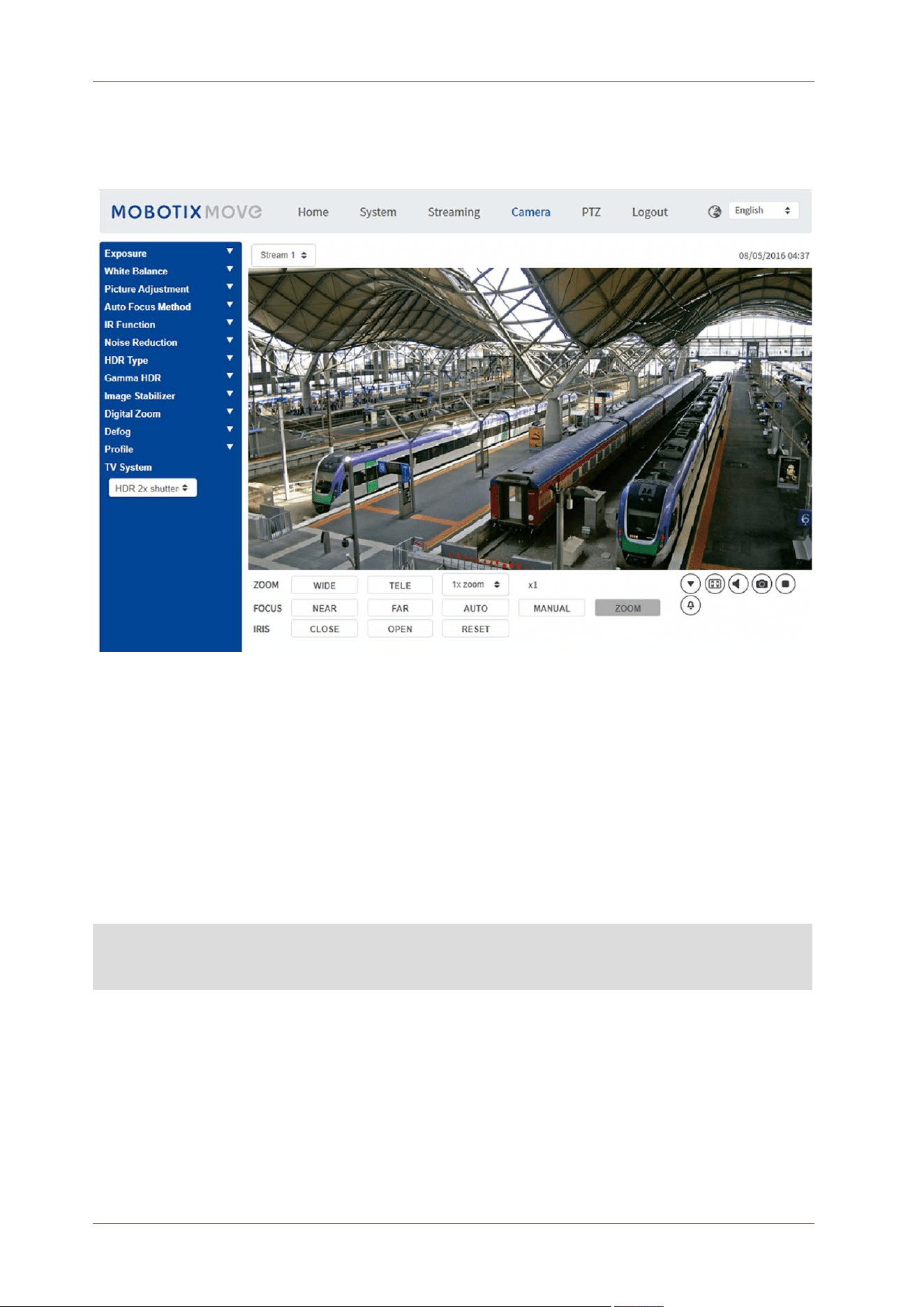
The “Camera” Tab
Exposure
To edit the exposure settings, select Camera> Exposure.
Exposure is the amount of light received by the image sensor. It is determined by the width of lens
diaphragm opening, the shutter speed and other exposure parameters. With these items, you can
define how the Auto Exposure function works. You can select one of the exposure modes according
to the operating environment. Each exposure mode is specified as follows.
NOTE! The available settings and the shutter speed range will vary depending on the lens/CMOS
sensor combination.
Menu Reference
The “Camera” Tab
95 / 130

Menu Reference
The “Camera” Tab
Auto Mode
n
Max Gain
Maximum Gain can be set to reduce image noises. The Max Gain ranges from 1dB to 24dB, or
select Off to disable the function. The default setting is 24dB.
n
Auto Iris
In this mode, the camera will automatically adjust the iris to suit the environment illumination.
The minimum shutter speed can be set from 1/30 to 1 sec. (NTSC) or 1/25 to 1/1.5 sec. (PAL).
AGC (Auto Gain Control) will function automatically according to the light conditions of the sub-
ject.
n
P-Iris Priority Mode
The minimum shutter speed can be set from 1/500 to 1/2 sec. (NTSC) or 1/425 to 1/3 sec. (PAL).
n
Iris Size Setting
Alternatively, you can manually adjust the iris size by selecting Manual. Click
and to adjust the iris size. Alternatively, you can manually adjust the iris size by
selecting Manual. Click and to adjust the iris size.
n
Minimum Shutter Speed
The minimum shutter speed can be set from 1/30 to 1 sec. (NTSC) or 1/25 to 1/1.5 sec.
(PAL).
n
Iris Priority Mode
In this mode, it is the iris that has premier priority in control of the exposure. The range of the
iris size is from 0 to 9, or select Full open to fully open the iris. The minimum shutter speed
can be set from 1/30 to 1 sec. (NTSC) or 1/25 to 1/1.5 sec. (PAL).
n
Auto Shutter Mode
In this mode, the camera will automatically adjust the shutter speed and the iris size according
to the light intensity. It is also effective if a fixed iris lens is being used. The minimum shutter
speed range is configurable from 1/500 to 1 sec. (NTSC) or 1/425 to 1/1.15 sec. (PAL).
n
Shutter Priority Mode
In this mode, it is the shutter speed that takes the main control of the exposure. The range is
configurable from 1/500 to 1/30 sec. (NTSC) or 1/425 or 1/25 sec. (PAL).
Manual Mode
With this mode, you can select the suitable shutter speed, iris size and gain value according to the
environmental illumination. The shutter speed ranges from 1/67500 to 1 sec. (NTSC) or from 1/67500
to 1/1.5 sec. (PAL).
96 / 130

The range of the iris size is from 0 to 9, or select Full open to fully open the iris. The gain value
range is from 3dB to 48dB, or select Off to disable the function.
NOTE! The Iris Size setting is only available for models with Zoom Lens.
NOTE! For Motorized Lens models, the iris size setting differs. To set the iris size, click on ,
and the camera will auto detect the best iris size for the environment. If necessary, users still can
manually adjust the iris size by selecting and . Alternatively, click on to reset
the iris size. The iris size will be set to the largest. Then, you can manually adjust the iris size by
selecting and .
White Balance
To edit the white balance settings, select Camera> White Balance.
A camera needs to find reference color temperature, which is a way of measuring the quality of a
light source, for calculating all the other colors. The unit for measuring this ratio is in degree Kelvin
(K). You can select one of the White Balance Control modes according to the operating envir-
onment. The following table shows the color temperature of some light sources for reference.
Light Sources Color Temperature in K
Cloudy Sky 6,000 to 8,000
Noon Sun and Clear Sky 6,500
Household Lighting 2,500 to 3,000
75-watt Bulb 2,820
Candle Flame 1,200 to 1,500
Auto Mode
The Auto White Balance mode is suitable for environments with light source having color tem-
perature in the range roughly from 2700K to 7800K.
ATW Mode (Auto Tracking White Balance)
With Auto Tracking White Balance function, the white balance in a scene will be automatically adjus-
ted while temperature color is changing. The AWB.wide mode is suitable for environments with light
source having color temperature in the range roughly from 2500K to 10000K.
Menu Reference
The “Camera” Tab
97 / 130

Menu Reference
The “Camera” Tab
AWB.normal
The AWB (Auto White Balance).normal mode is suitable for environments with light source having
color temperature in the range roughly from 2700K to 7800K.
AWB.wide
With AWB (Auto White Balance).wide function, the white balance in a scene will be automatically
adjusted while temperature color is changing. The AWB.wide mode is suitable for environments with
light source having color temperature in the range roughly from 2500K to 10000K.
AWB.all
The AWB (Auto White Balance).all mode is suitable for environments with light source having color
temperature under 2500K or over 10000K.
Smart Mode
The Smart mode is suitable for environments with one single background color which is strongly sat-
urated, for instance, in a forest.
One Push
With One Push function, white balance is adjusted and fixed according to the scene the camera cur-
rently sees. This function is best for situations with minimal scene changes and continuous lighting.
The function is suitable for light sources with any kind of color temperature. Follow the steps below
to set the white balance.
n
Point the camera to the monitoring area.
n
Select One Push in the White Balance setting menu
n
Click the button to adjust the color tone of the live images.
NOTE! In this mode, the value of white balance will not change as the scene or the light source var-
ies. Therefore, users might have to re-adjust the white balance by clicking the button again
when needed.
Smart Touch Mode
With Smart Touch function, you can select an area in the camera scene as the reference point for
white balance. Please ensure that the background color of the selected area is white. Smart Touch
98 / 130
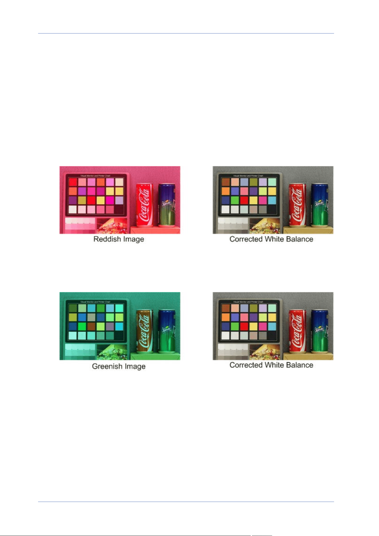
function is suitable for environments with unchanged brightness level.
Manual Mode
In this mode, you can manually adjust the White Balance value. Input a number between 0 to 249
for “Rgain/Bgain” to adjust the red/blue illuminant on the Live Video Pane. The following describes
several situations that might occur during the White Balance manual adjustment.
n
The video image turns reddish (as the left picture below).
The higher the Rgain value, the redder the image will be. To solve the problem, reduce the
Rgain value, and the video image will turn less reddish.
n
The video image turns greenish (as the left picture below).
The lower the Rgain value, the greener the image will be. To solve the problem, Increase the
Rgain value, and the video image will turn less greenish.
Menu Reference
The “Camera” Tab
99 / 130
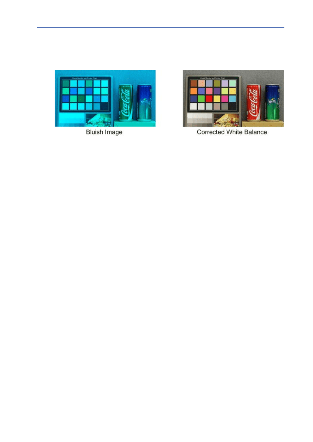
Menu Reference
The “Camera” Tab
n
The video image turns bluish (as the left picture below).
The higher the Bgain value, the bluer the image will be. To solve the problem, reduce the
Bgain value, and the video image will turn less bluish.
100 / 130
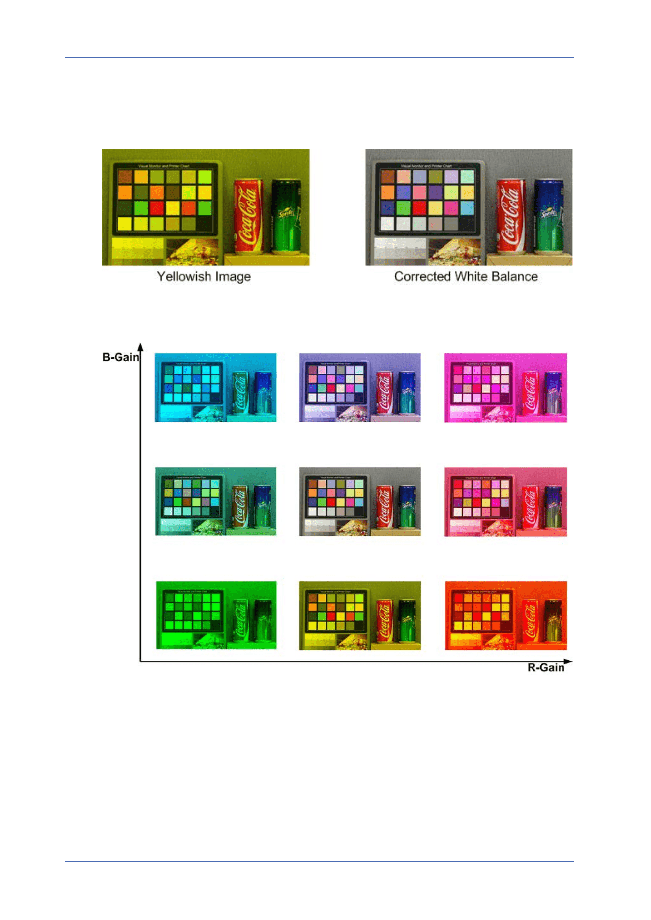
n
The video image turns yellowish (as the left picture below).
The lower the Bgain value, the yellower the image will be. To solve the problem, Increase the
Bgain value, and the video image will turn less yellowish.
The following image displays the general color shifts of the scene when different Rgain/Bgain
combinations are applied.
Picture Adjustment
To edit the picture adjustment settings, select Camera> Picture Adjustment.
n
Brightness
The brightness level of the images is adjustable from -12 to +13. The default value is 0.
Menu Reference
The “Camera” Tab
101 / 130

Menu Reference
The “Camera” Tab
n
Sharpness
The sharpness level of the images is adjustable from +0 to +15. The edge of the objects is
enhanced as the sharpness level increases. The default value is +4.
n
Contrast
The contrast level of the images is adjustable from -6 to +19. The default value is 0.
n
Saturation
The saturation level of the images is adjustable from -6 to +19. The default value is 0.
n
Hue
The hue level of the images is adjustable from -12 to +13. The default value is 0.
Color Style
To edit the color style settings, select Camera>Color Style.
Color style can automatically adjust the brightness, allowing users to select the best color style mode
based on the operating environment.
n
Normal
The default setting is normal mode.
n
Dark Detail Brighter
This mode increases brightness on dark areas of the image.
n
Highlight Detail Brighter
This mode increases brightness on general-illuminated areas of the image.
IR Function
To edit the IR function settings, select Camera> IR Function.
Day/Night Function
This item is for users to define the action of the IR cut filter and IR LED lights. Refer to the descrip-
tions of each option below to select a suitable mode.
n
Auto
With this mode, the camera will decide when to remove the IR cut filter. Please refer to
Day/Night Threshold, p. 103 for further details.
102 / 130

n
Night
Use this mode when the environment light level is low. The IR cut filter will be removed to
allow the camera to deliver clear images in black and white.
n
Day
Select this mode to turn on the IR cut filter. The IR cut filter can filter out the IR light and
allows the camera to deliver high quality images in color.
n
Light Sensor(Default)
In this mode, for cameras with built-in IR LED modules, the light sensor will decide the occa-
sion to turn the IR LED lights on/off. For cameras with non-IR modules, the light sensor will
decide the occasion to take the IR cut filter on/off.
n
Light On (Built-in IR LED Modules Only)
In this mode, IR LED lights will always be on.
n
Light Off (Built-in IR LED Modules Only)
In this mode, IR LED lights will always be off.
n
Smart
With Smart mode, the camera will decide the occasion to remove the IR cut filter. The Smart
mode mechanism can judge whether the main light source is from IR illumination. If so, the
IR cut filter will be kept removed (i.e. monochrome/night mode).
NOTE! It is recommended to select “Smart Mode” when the camera sets high zoom ratio
for close-up view.
Day/Night Threshold
This item is for users to set when the camera should switch from day mode to night mode or vice
versa. The camera will sense the surrounding brightness, and the threshold value stands for the
level of the light. Once the camera detects the light level reaches the set threshold, the camera will
automatically switch to Day/Night Mode. The range of the level is from 0 to 10, (darker = 0; brighter
= 10).
n
Night Mode to Day Mode
The lower the value, the earlier the camera switches to Day mode. The default value is 7.
n
Day Mode to Night Mode
The higher the value, the earlier the camera switches to Night mode. The default value is 3.
NOTE! Equipped with different CMOS sensors, the time the camera switches to Day/Night
mode may also vary from models to models even if the threshold is set to the same value.
Menu Reference
The “Camera” Tab
103 / 130

Menu Reference
The “Camera” Tab
IR Light Compensation
With the IR Light Compensation function, the camera can prevent the center object close to the cam-
era from being too bright when IR LED lights are turned on.
NOTE! IR Light Compensation function is NOT available when Auto Exposure Window Setting
function is enabled.
Noise Reduction
To edit the noise reduction settings, select Camera> Noise Reduction.
The camera provides multiple Noise Reduction options for delivering optimized image quality espe-
cially in extra low-light conditions.
3DNR
3DNR (3D Noise Reduction) function delivers optimized image quality especially in extra low-light con-
ditions.
Different levels of 3DNR are provided, including 3DNR Low, 3DNR Mid and 3DNR High. Higher level of
3DNR generates relatively enhanced noise reduction.
2DNR
2DNR (2D Noise Reduction) function delivers clear images without motion blurs in extra low-light con-
ditions.
Select on to turn on 2DNR function; otherwise, select off to turn off 2DNR function.
ColorNR
In a dark or insufficient light environment and the camera is under color mode, ColorNR (Color Noise
Reduction) can eliminate color noise.
Three levels of ColorNR, including Color Low, Color Mid and Color High, are provided. The higher
level of ColorNR generates relatively enhanced noise reduction.
HDR Type
To edit the HDR type settings, select Camera> HDR Type.
104 / 130

The HDR type controls the low-light performance of the camera. You can switch between Normal
and Linear mode.
Gamma HDR
To edit the Gamma HDR settings, select Camera> Gamma HDR.
Gamma HDR function solves high contrast or changing light issues. Different level options for
Gamma HDR are Low, Mid, Hi, and Auto. Select the suitable Gamma HDR mode based on the bright-
ness of the scene. Note that image noise may appear when activating this function.
NOTE!
Auto mode is not available under these conditions:
n
TV system has been set to Linear mode
n
TV system has been set to HDR mode and the Shutter ratio under HDR Type is set as
Fixed
Image Stabilizer
To edit the image stabilizer settings, select Camera> Image Stabilizer.
With the Image Stabilizer function, the camera can keep the image steady and suppress vibrating
effects on images caused by external vibration.
NOTE!
n
The image stabilizer is only available if the video format in TV System, p. 107 has been set
to WDR 2 Shutter.
n
When activating the image stabilizer, the field of view is reduced by a perceptible amount,
both horizontally and vertically. This is due to the stabilizing algorithm of the camera,
which needs about 10% of the image at each side to detect image movement and this por-
tion cannot be used in the final image.
Follow the instructions below to activate the function.
1. Select On from the Stabilizer drop-down list to enable the Image Stabilizer function.
2. Select On from the Auto Calibration drop-down to activate the auto calibration function.
3. Alternately, users can click the Calibrate button for manual calibration. Be sure not to move
the camera for 3 seconds for calibration accuracy.
To disable the function, select Off from the Stabilizer drop-down list.
Menu Reference
The “Camera” Tab
105 / 130

Menu Reference
The “Camera” Tab
NOTE!
n
Do NOT use PTZ functions when activating manual calibration.
n
The Digital Zoom function and the Privacy Mask/Zoom Factor function will be disabled when
the Image Stabilizer function is activated.
Click on Save to apply and store the settings.
Digital Zoom
To edit the digital zoom settings, select Camera> Digital Zoom.
Select On to enable digital zoom, select Off to disable the function.
Defog
Click on Camera> Defog and select On to improve the camera images in foggy conditions. In this
mode, the camera applies contrast enhancement to improve the colors in the images.
Profile
To edit the camera profile settings, select Camera> Profile.
Camera Profile allows users to setup the desired image parameters for specific environments with dif-
ferent time schedules. You can setup at most 10 sets of camera parameter configuration under the
Camera tab. To enable this function, users must setup the schedules in advance. Refer to section
Schedule for further details of schedule setup. Then, follow the steps below to setup a camera pro-
file.
Camera Profile Setup
1. In the “Camera” tab, setup the camera parameters, such as White Balance, Picture Adjustment,
etc., excluding TV System.
2. Click on Profile and its setting menu will be displayed. Select a number from the Num drop-down
menu.
3. Input a name for the profile in the Name field.
106 / 130

4.
Click on below the Name field. The camera configuration is saved and applied to the pro-
file. Now a camera profile is created and saved.
5. Select a profile from the Num drop-down menu.
6. Tick the By schedule box. Check the desired schedule(s) from the Schedule drop-down menu.
Multiple schedules can be applied to one profile.
7.
Click on below By schedule.
8. Follow the steps above to set the rest of the profiles.
Now, the camera will automatically switch profiles according to the schedule. Alternatively, manu-
ally select a number from the Num drop-down menu. Then, click on , the camera will load
and apply the setting of the profile.
NOTE! If users wish to set the camera parameters to factory default setting, select Normal from
the Num drop-down menu. The camera will start loading the default values.
NOTE! Users MUST set the camera parameter of the last profile as the default setting. Thus, if
there are gaps among schedules, the camera will apply the setting of the last profile.
TV System
To edit the TV system settings, select Camera> TV System.
Select the video format that matches the present TV system from the drop-down menu. The fol-
lowing table shows the available video formats for different types of models. The supported video
formats for each model are marked by “✓”.
Video Format 2MP Low-Light Video Analytics Speed Dome
NTSC 30 fps ✓
WDR 2 Shutter ✓
PAL 25 fps ✓
WDR 2 Shutter ✓
Menu Reference
The “Camera” Tab
107 / 130
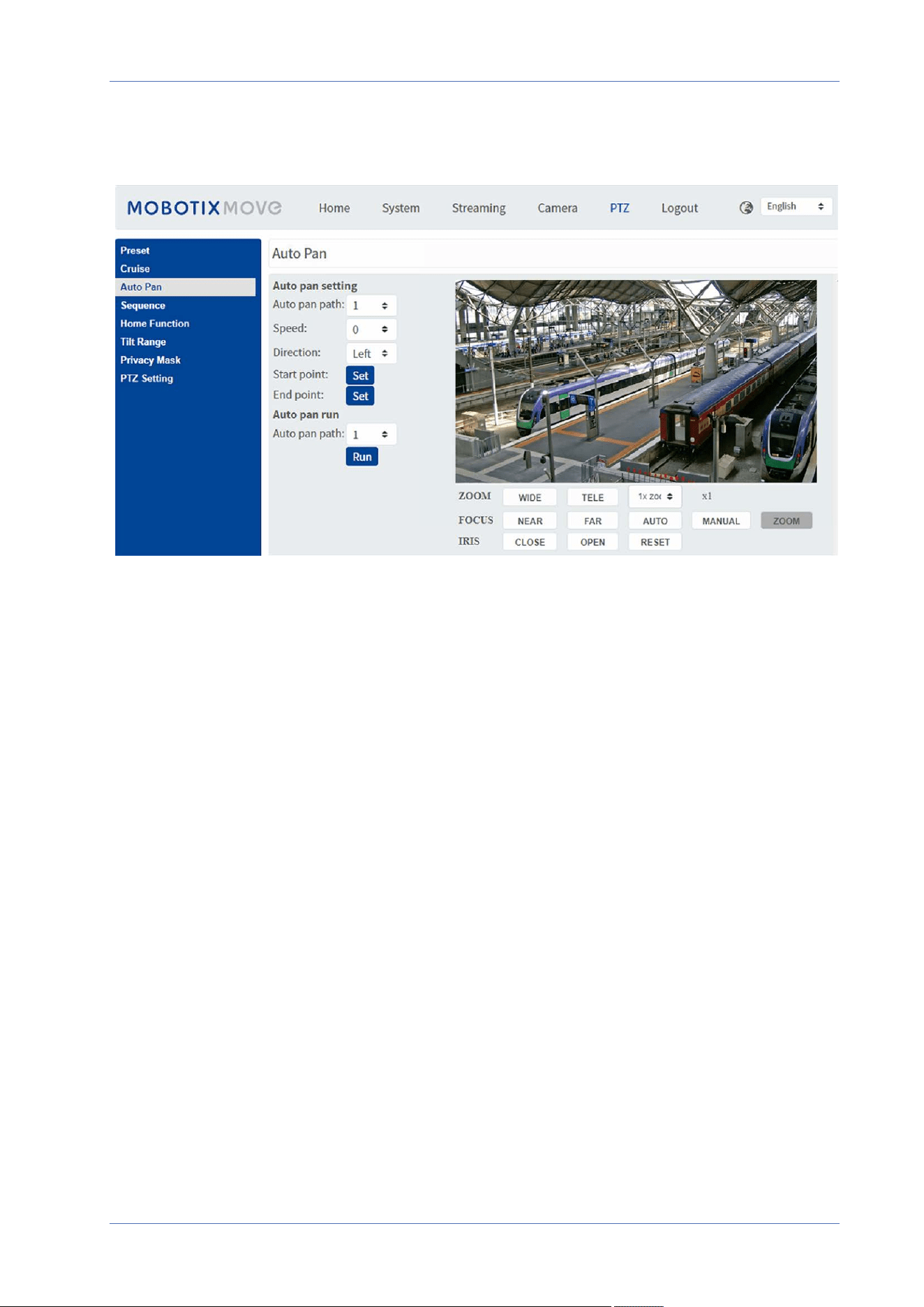
Menu Reference
The “PTZ” Tab
The “PTZ” Tab
Preset
To edit preset points, select PTZ > Preset.
The camera supports up to 256 preset points. Please refer to the instructions below to set a preset
point.
Preset Setting
Follow the steps to set up a preset point.
1. Move the cursor to the live view pane.
2. Left click and drag the red pointer with the PTZ controls to a desired position and adjust the fine
zoom/focus ratio.
3. Assign a number for the current position from the drop-down Number list (click PrePage or Nex-
tPage button to reach number 1 to 256), and enter its descriptive name.
4. Click Set to save the settings.
108 / 130

Preset Go
To have the camera move to a specified preset position, select the preset point from the Preset list
(click PrePage or NextPage button to reach preset number 1 to 256). The camera will move to the
target position.
Cruise
To edit cruise programming, select PTZ > Cruise.
The camera supports up to eight cruise paths. Please follow the instructions below for cruise path
setup.
Cruise Setting
Refer to the steps below to set up a cruise path.
1. Select a path number from the drop-down list.
2. Move the cursor to the live view pane, and move the camera to a desired view (PTZ controls) as
the start point of a Cruise Path.
3. Click Set button of Record Start and start programming the Cruise Path via PTZ controls.
4. When finishing programming, click the Set button of Record End to complete recording the
Cruise Path.
Cruise Run
Select the specified cruise path from the drop-down list, click the Run button, and the camera will
start touring around as recorded.
To view the camera touring in full screen mode, move the cursor onto the live view pane, right-click
and left-click to select Fullscreen. Then you can view the camera navigation in full screen.
To stop a cruise path, simply move the cursor to the live view pane and move the camera in any dir-
ection.
Auto Pan
To edit auto pan programming, select PTZ > Auto Pan.
The camera supports up to four Auto Pan paths. Please refer to the instructions below to set an
Auto Pan path.
Menu Reference
The “PTZ” Tab
109 / 130

Menu Reference
The “PTZ” Tab
Auto Pan Setting
Follow the steps to set up an Auto Pan path.
1. Select a path number from the drop-down list.
2. Select the speed ratio from the Speed drop-down list; the speed ratio ranges from 0 (low) to 3
(fast).
3. Choose to run the auto pan path in right/left direction from the Direction drop-down list.
4. Move the cursor to the live view pane, and move the camera to a desired view as the Start Point
of an auto pan path.
5. Click Set button of Start Point and the current view will be automatically saved as the start
point of the auto pan path.
6. Move the camera to another desired position as the end point of the auto pan path.
7. Click Set button of End Point to save the setting.
NOTE! The zoom ratio of an auto pan’s start point remains the same throughout the path.
Auto Pan Run
Select the specified auto pan path from the drop-down list, click the Run button, and the camera will
start moving horizontally as recorded.
To view the camera panning in full screen mode, move the cursor onto the live view pane, right-click
and left-click to select Fullscreen. Then you can view the camera navigation in full screen.
To stop running an auto pan path, simply move the cursor to the live view pane and move the cam-
era in any direction.
Sequence
To edit sequence line programming, select PTZ > Sequence.
The camera supports up to eight sequence lines; each sequence line consists of up to 64 Preset
points. Please refer to the instructions below to program a sequence line.
NOTE! Before setting this function, users must pre-define at least two Preset points.
Sequence Settings
Click the Edit button of Sequence Setting to enter the menu.
110 / 130

n
Sequence Line
Select the number of sequence lines to be set from the drop-down list in the top of the
Sequence Setting menu.
n
Sequential Preset Points
Set up each preset point of the programmed sequence line in order. Select a preset point
from the Name list for the specified number of preset points and enter both Dwell Time (0 to
127) and Speed (0 to 14) into the corresponding fields. When finishing the sequential setting
of preset points, click the Save button in the top of the Sequence setting menu.
Sequence Run
Select the specified sequence line from the drop-down list, click the Go button, and then the cam-
era will start moving forward each scene sequentially as programmed.
To view the camera executing a sequence line in full screen mode, please move the cursor onto the
live view pane, right-click and left-click to select Fullscreen. Then you can view the camera nav-
igation in full screen.
To stop running the sequence line, simply move the cursor to the live view pane and move the cam-
era in any direction.
Home Function
To edit the Home settings, select PTZ > Home Function.
You can set an operation mode to ensure constant monitoring. If the camera idles for a period of
time, the selected function will be activated automatically; this is the Home function. The Home
function allows constant and accurate monitoring to avoid the camera idling or missing events.
Home Setting
n
Switch
Select On or Off to activate or disable the Home function. Then click the Set button to apply
the setting.
n
Time
Time in this context represents the duration of camera idle time previous to running a preset
point/cruise line/auto pan path/sequence line. When the Home function is activated, the cam-
era will start to count down when it idles, and then execute the predefined action as time
expires. The time period ranges from 1 min. to 128 min.; specify it in the field.
Click Set to save the settings.
Menu Reference
The “PTZ” Tab
111 / 130

Menu Reference
The “PTZ” Tab
n
Type & Line
Select a Home action type (Preset Point/Cruise Line/Auto Pan Path/Sequence Line) and specify
the number of preset points/cruise lines/auto pan paths/sequence lines from the drop-down
Type and Line lists.
Click Set button to save the Home settings.
Tilt Range
To edit the tilt range settings, select PTZ > Tilt Range.
The camera’s tilt angle is adjustable from minimum −20° to maximum +100°. Enter the desired min-
imum and maximum tilt angles into the corresponding fields.
Click Set button to save the tilt angle settings.
Privacy Mask
To edit privacy masks, select PTZ > Privacy Mask.
The Privacy Mask function aims to avoid any intrusive monitoring. When setting a mask, it is sug-
gested to set it at least twice bigger (height and width) than the masked object. The camera will
assume the center of the selected view as the starting point. It is therefore advisable to keep the tar-
get object/region nearly positioned in the center of the scene.
Mask Setting
n
Switch
Select On or Off to activate or disable the Privacy Mask function. Click Set button to apply the
setting.
n
Color
Select a color from the Color drop-down list for the specified Privacy Mask. Click Set button to
apply the setting.
n
Mask Number (1~20)
Specify the number of the programmed privacy mask in the entry field.
112 / 130

n
Zoom Factor
Normally, a privacy mask will be repositioned and resized to cover the masked area
whenever pan/tilt/zoom functions are used. the zoom factor allows users to hide the mask if
the zoom ratio is set lower than the original ratio.
For example, when the privacy mask is set at a certain zoom ratio (e.g. 5x), the privacy mask
will be resized when the camera is zoomed in (e.g. from 5x to 20x); however, when the cam-
era zooms out (e.g. from 5x to 2x), the privacy mask will be hidden. Select On or Off to activ-
ate or disable the Zoom Factor function. Follow the steps below to set up a privacy mask.
1. Set Switch to On and click the Set button to turn on the Privacy Mask function.
2. Select a color for the mask from the Color drop-down list and click the Set button to apply the
color setting.
3. Specify the mask a number, e.g. 17. If Zoom Factor is needed, select On to enable this function.
Then, click the Add button and a privacy mask will be displayed on the Live Video Pane on the
right.
4. To shift the mask to the intended location, move the mouse cursor to the center of the mask
and click and drag.
5. To change the shape and the size of the mask, click any edge of the mask and draw it out-
ward/inward.
6. If needed, set up Zoom/Focus/Iris.
7. Click Set button to save and apply the setting. The privacy mask will be displayed in the color
set previously.
If you want to edit the previously-set mask, input the mask number in the Mask(1~20) entry field
and click the Edit button. The camera will go to the set location and display the mask. You can then
follow Steps 4 to 6 to edit the mask.
To cancel mask editing, just click the Return button to exit the editing.
Mask Clearing
To delete an existing privacy mask, select it from the drop-down list and click the Clear button. The
selected privacy mask will disappear.
Menu Reference
The “PTZ” Tab
113 / 130

Menu Reference
The “PTZ” Tab
PTZ Setting
To edit the PTZ settings, select PTZ > PTZ Setting.
Flip (Image Flip)
You can track an object continuously when it passes under the camera by setting Flip to M.E. Mode
(mechanical mode) or digital flip Image Mode:
n
M.E. Mode
M.E. is a standard mechanical operation. As the camera tilts to the maximum angle, it will pan
180°, and then continue tilting to keep tracking objects.
n
Image Mode
The digital image flip mode allows tracking the objects seamlessly. Compared to M.E. Mode,
there is hardly any perceptible delay.
NOTE!
n
The Flip setting is only controlled manually. If a preset position or a point for other function
(e.g. a sequence) is set in the position that can only be reached through FLIP motion, when
the Flip function is turned off, the position cannot be reached any more.
n
To make the camera tilt between a specific range, such as -10° to +100° or -10° to +190°,
please go to the Tilt Range setting page to set the tilt angle range. Otherwise, the camera
will tilt 90° as the default setting.
Speed by Zoom
This function allows the camera to adjust the pan/tilt speed automatically by the internal algorithm
when the zoom ratio is changed. The rotating speed will become slower as the zoom ratio gets lar-
ger. Click on the Set button to save the setting.
Auto Calibration (Servo Feedback)
Integrating Servo Feedback technology, the camera would calibrate and precisely return to the pre-
vious position without stalling when the deviation of dome pivot is detected. Select On and click on
the Set button to activate the setting.
Set Pan Zero
Click on the Set button to set the camera’s current position as the start point for panning (0 degree).
Click on Save to apply and store the settings.
114 / 130

The “Logout” Tab
Click on the tab Logout on the top of the page, and the login window will pop up. This enables log-
ging in with a different username.
Menu Reference
The “Logout” Tab
115 / 130

Menu Reference
Appendix A: Installing UPnP Components
Appendix A: Installing UPnP Components
Please follow the instructions below to install UPnP components on Windows computers.
1. In Windows, go to Start, click on Control Panel, and then double-click on Add or Remove Pro-
grams.
2. Click on Add/Remove Windows Components in the Add or Remove Programs page.
3. Select Networking Services from the Components list in Components Wizard window of the Win-
dows, and then click Details.
4. Select UPnP User Interface in the Networking Services’ subcomponents list and then click on
OK.
5. Click on Next in the Windows Components Wizard window.
6. Click on Finish to complete installation.
Appendix B: Converting IP Addresses from
Decimal to Binary
Follow the example below to convert the IP addresses to binary numbers. Use the calculator on the
computer for conversion: Start> All Programs> Accessories> Calculator.
n
Windows7/8: Click View on the calculator and click Programmer.
n
Windows10/11: Click on the menu button and select Programmer.
116 / 130

The example below shows how to convert 192.168.2.81 to binary numbers.
1. On the left of the calculator, select Dec. Then enter the first decimal number of the IP address,
“192”. Select Bin and the number will be converted to binary number. Repeat the same pro-
cedure with the rest of decimal numbers. Remember to select Dec before entering the next
decimal number. Otherwise a decimal number cannot be entered. The table below shows the
binary representation of each decimal number.
Decimal Numbers Binary Numbers
192 11000000
168 10101000
2 10
81 1010001
2. Each binary number should have eight digits. If a binary number does not have eight digits,
please add leading zeros until it does. The binary number of each decimal number should be as
follows.
Decimal Numbers Binary Numbers
192 11000000
168 10101000
2 00000010
81 01010001
Therefore, the binary representation of IP address 192.168.2.81 is
11000000.10101000.00000010.01010001.
Menu Reference
Appendix B: Converting IP Addresses from Decimal to Binary
117 / 130

Menu Reference
AppendixC: List of Open/Closed IP Ports
AppendixC: List of Open/Closed IP Ports
The following tables list the ports for the TCP and UDP IP protocols on the MOBOTIX MOVE cameras.
TCP Protocol
Port number Service Default
Port number Service Default
80 HTTP open
443 HTTPS open
554 RTSP open
5555 UPnP open
UDP Protocol
Port number Service Default
68 DHCP open
161 SNMP closed
1900 UPnP open
3702 ONVIF Probe open
5353 Bonjour open
6666 Device Search (Dynacolor search tool) open
15070 audio talk (RTP from PC to IPCam) closed
15071 audio talk (RTCP) closed
18890 stream1 video multicast RTP port open
18891 stream1 video multicast RTCP port open
18900 stream2 video multicast RTP port open
18901 stream2 video multicast RTCP port open
18910 stream3 video multicast RTP port open
118 / 130

Port number Service Default
18911 stream3 video multicast RTCP port open
18920 stream4 video multicast RTP port open
18921 stream4 video multicast RTCP port open
18930 audio multicast RTP port open
18931 audio multicast RTCP port open
18940 meta-data multicast RTP port open
18941 meta-data multicast RTCP port open
19800 MxMessage system open
Menu Reference
AppendixC: List of Open/Closed IP Ports
119 / 130


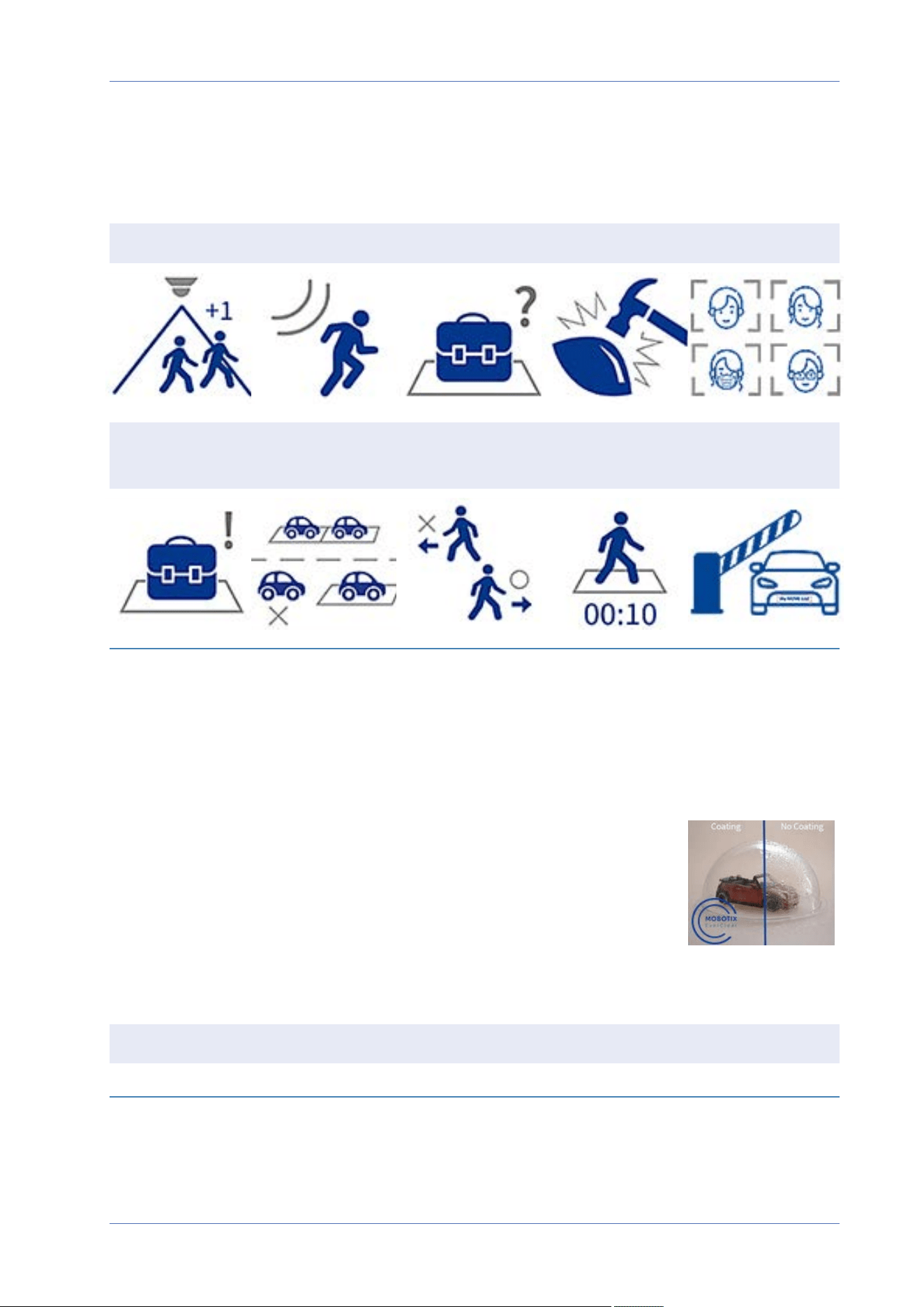
Technical Support Information
Technical Specifications
Technical Specifications
High-Quality DNN Edge Video Analytics
Counting Intrusion Removed Objects Sabotage Face Recognition
Abandoned
Objects
Stopped Vehicle Wrong Direction Loitering ALPR
The latest computer vision technology makes the DNN-accelerated video processing engine efficient
at the edge. This integrated engine provides high accuracy, real-time object tracking, and 10 (DNN-
based) video analytics functions including ALPR and human face recognition. Moreover, it allows sim-
ultaneous detection on multiple objects.
MOBOTIX EverClear Nano Coating
The new, groundbreaking MOBOTIX EverClear coating uses a special nano tech-
nology that transforms water droplets into an ultra-thin water film imme-
diately upon impact. This ensures the highest image quality in rain and
difficult environmental conditions and reduces maintenance costs due to its
“self-cleaning” effect.
Product Information
Product Name 2MP Low-Light Video Analytics Speed Dome
Order Code Mx-SD2A-230-LL-VA
122 / 130

Image Quality
Image Sensor 2MP 1/2.8” Progressive CMOS IMX662 (SONY STARVIS II)
Effective (Used) Pixels H x V = 1920x1080 (2MP)
Pixel Size 2.9µm
Frame Rate (maximum) WDR on/off:
H.265/H.264: 2MP@30 fps
MJPEG: 1080p@30fps
Dome Coating Superhydrophilic MOBOTIX EverClear nano coating transforms water
droplets into an ultra-thin water film upon impact. The coating
ensures best image quality in rain and difficult external conditions
and it reduces reflections and noise in low-light scenarios. EverClear
is dirt-repellent and increases the stability as well as the scratch-res-
istance of the dome, further reducing maintenance efforts. Coating
endurance up to 3 years depending on environmental conditions and
cleaning treatment.
Hardware Design
Processor Ambarella CV25
Memory RAM: 1024MBytes,
FLASH: 512MBytes
Lens
Minimum Illumination Color: 0.01Lux
B/W: 0.001Lux
F1.6, AGC=on, 30 IRE, 1/1s
Lens Characteristics Zoom Lens: Zoom, Auto Focus, P-IRIS, Auto-IRIS
Focal Length: 4.3 to 129mm
Aperture: F1.6 – F4.7
Horizontal Field of View: 59.3° (Wide), 2.3° (Tele)
Vertical Field of View: 34.9° (Wide), 1.4° (Tele)
Technical Support Information
Technical Specifications
123 / 130

Technical Support Information
Technical Specifications
Camera
Shutter Speed (Auto) 1 to 1/10000s
Shutter Speed (Manual) WDR: 1/37500s
Linear: 1/75000s
Shutter Priority Mode Up to 1/45s
WDR Up to 130 dB
Electronic Image Stabilizer
(EIS)
Yes
Auto Object Tracking On/off (object-based DNN algorithm: humans/vehicles selectable)
Zoom Optical: 30x, Digital: 10x
Image Settings Color, Brightness, Sharpness, Contrast, White Balance, Exposure Con-
trol, 2DNR, 3DNR, NR by Motion, Masking, Text Overlay
Image Rotation 90°, 180°, 270°
Servo Feedback Yes
PTZ Features
Preset positions Up to 256 positions, 1 Home position
Sequences Up to 8 sequences with 64 preset positions each
Cruise Paths Up to 8
Auto Pan Paths Up to 4
Display Position Pan/Tilt degrees can be displayed in live image
Pan Range 360° endless
Tilt Range –10° to +100°
Pan Speed Manual Pan Speed: 0.1°–90°/s
Preset Pan Speed: 400°/s
Tilt Speed Manual Tilt Speed: 0.1°–55°/s
Preset Tilt Speed: 300°/s
Joystick/Keyport Control RS485 protocols DSCP, Pelco-D and Pelco-P
Video Analytics Presets can be combined with 1 selectable integrated video analytics
feature
124 / 130

Video Codec
Compression/Encoding H.265/H.264/MJPEG
Streaming Up to 9 individually configurable streams (4 streams, 4 sub streams, 1
Quad stream) in H.264/H.265/MJPEG;
configurable resolution, frame rate, bandwidth LBR/VBR/CBR in
H.265/H.264
Audio Codec
Compression/Encoding G.711/G.726/AAC/LPCM
Streaming Bi-directional
Audio Input Line In
Max. 2.28 V
pp
for line signal
Input impedance: 33kΩ
Audio Output Line Out
Output resistance: 220Ω
Output voltage: 1V
rms
Cyber Security Features
Password Protection Yes (including “forced” password change during
initial setup)
IP address filtering Yes (to restrict unauthorized access based on IP
addresses)
IEEE 802.1X network access control Yes (for advanced network security and authen-
tication)
Digest authentication Yes (for secure user authentication)
AES encryption for password protection Yes (to ensure strong encryption for password
storage)
HTTPS/SSL (using TLS) Yes (TLS 1.2 default, TLS 1.0/1.1 optional select-
able)
User and Group Management Yes (for fine-grained access control)
VPN Yes (to establish secure network connections)
Technical Support Information
Technical Specifications
125 / 130

Technical Support Information
Technical Specifications
Digitally signed firmware Yes (to prevent firmware file tampering)
RSA encryption Yes (to support stronger ciphers; supported: RSA
(2048 bits), AES-128, AES-256, SHA-256, SHA-384)
Network
Interface 10/100 Mbps Ethernet
Supported Protocols ARP, PPPoE, IPv4/v6, ICMP, IGMP, QoS, TCP, UDP, DHCP, UPnP, SNMP,
SMTP, RTP, RTSP, HTTP, HTTPS, FTP, NTP, DDNS, SMBv2, VPN
ONVIF conformance Supports profiles S/G/T/M
Supported Browsers All current browsers (e.g. Microsoft Edge, Firefox, Google Chrome,
Opera, etc.) are supported.
System Integration
Base Video Analytics
n
Motion detection
n
Audio detection
Enhanced Video Analytics
(linkable to PTZ presets)
n
Abandoned objects
n
Intrusion (object classification)
n
Sabotage
n
Wrong direction
n
Loitering (object classification)
n
Object counting (object classification)
n
Object removal
n
Stopped vehicle (object classification)
2 analytics functions can be activated simultaneously
126 / 130

DNN (Deep Neural Network)
based video analytics
(linkable to PTZ presets)
n
Face Recognition (incl. gender & age estimation)
n
Number Plate Recognition – supported countries:
Armenia, Austria, Azerbaijan, Belarus, Belgium, Bosnia and
Herzegovina, Bulgaria, Croatia, Cyprus, Czech Republic, Den-
mark, Estonia, Finland, France, Georgia, Germany, Greece, Hun-
gary, Ireland, Israel, Italy, Japan, Kazakhstan, Kyrgyzstan,
Latvia, Lithuania, Luxembourg, Moldova, Monaco, Montenegro,
Netherlands, North Macedonia, Norway, Poland, Portugal,
Romania, Russia, Serbia, Slovakia, Slovenia, Spain, Sweden,
Switzerland, Taiwan, Turkey, Ukraine, United Kingdom, Uzbek-
istan, Vietnam
Event Triggers
n
External input
n
Analytics
n
Network failure detection
n
Periodical event
n
Manual trigger
n
MxMessageSystem messages
Event Actions
n
External output activation
n
Video and audio recording to edge storage
n
File upload: FTP, network share and email
n
Notification: HTTP, FTP, email
n
MxMessageSystem messages
General
Housing material Metal and plastic
Power Requirements PoE+ IEEE802.3at, class 4, max 25.5 watt
AC24V, max 29.04 watt, max 53.24 VA
PoE Modes Supported ModeA or ModeB
Connectors
n
RJ45
n
4 x Alarm in, 2x Alarm out, Audio in, Audio out, RS485 terminal
block
n
AC24V terminal block
n
CVBS connector (available with max. 2 activated streams)
Technical Support Information
Technical Specifications
127 / 130

Technical Support Information
Technical Specifications
Video Storage Micro SD/SDHC/SDXC card support up to 1TB (using SD card
adapter),
Support for recording to NAS, MOBOTIX HUB, MOBOTIX MOVE NVR
Remotely Upgradable Yes
Environmental Protection
Class
IP66/IK10
Operating Temperature –40 to 55°C/-40 to 131°F with heater
Relative Humidity 10 to 90% non-condensing
Storage Conditions –20 to 70 °C/–4 to 158 °F
Approvals EMC: CE/FCC
Safety: LVD
MTBF 50,000hours
Warranty 5years; mechanically wearable parts (motor, gears, belts, etc.)
excluded
Dimensions ø 210 x 294.5mm
Weight 3100g
NOTE! Observe the MOBOTIX MOVE Installation Hints document to ensure optimum performance
of the camera features.
Alarm Input/Output Current and Voltage
Alarm In Alarm Out
5V with 10kΩ pull up, 50mA 400V DC/AC, 120mA
128 / 130


EN_09/23
MOBOTIX AG • Kaiserstrasse • D-67722 Langmeil • Tel.: +49 6302 9816-103 • [email protected] • www.mobotix.com
MOBOTIX is a trademark of MOBOTIX AG registered in the European Union, the U.S.A., and in other countries. Subject to change without
notice. MOBOTIX do not assume any liability for technical or editorial errors or omissions contained herein. All rights reserved. ©MOBOTIX
AG2020