Loading ...
Loading ...
Loading ...
6
INTRODUCTION
Tablet Display Functions
TABLET DISPLAY FUNCTIONS
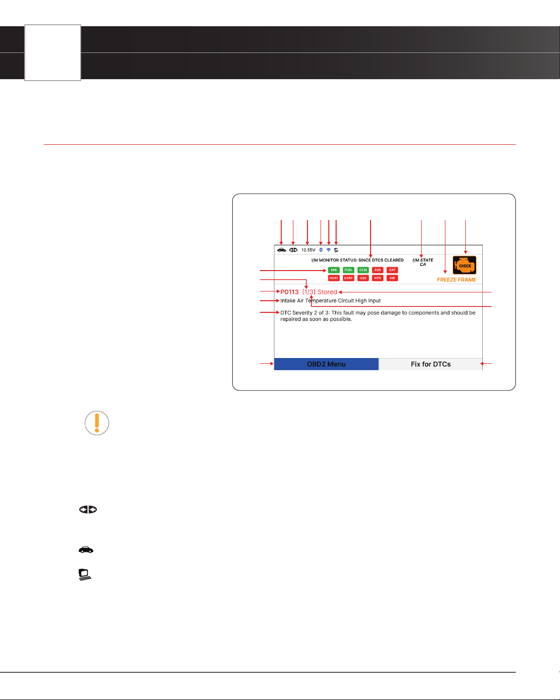
See Figure 2 for the locations of items 1 through 19 below.
1. I/M MONITOR STATUS: SINCE DTCs CLEARED eld - Identies the I/M Monitor status area.
2. Monitor icons - Indicate which
Monitors are supported by the vehicle
under test, and whether or not the
associated Monitor has completed
its diagnostic testing (Monitor status).
When a Monitor icon is solid green,
it indicates that the Monitor has
completed both Since DTCs Cleared
and This Drive Cycle. When a Monitor
icon is ashing red, it indicates that
the Monitor has not completed testing
Since DTCs Cleared. When a Monitor
is Green-Gray, it indicates that the
monitor has not completed testing This
Drive Cycle. When a Monitor is Red-
Gray, it indicates that the monitor has
been disabled This Drive Cycle.
NOTE: The I/M Monitor Status icons are associated with INSPECTION and
MAINTENANCE (I/M) READINESS STATUS. Some states require that all vehicle
Monitors have run and completed their diagnostic testing before a vehicle can be
tested for Emissions (Smog Check). A maximum of fteen Monitors are used on
OBD2 systems. Not all vehicles support all fteen Monitors. When the Tablet is linked
to a vehicle, only the icons for Monitors that are supported by the vehicle under test
are visible on the display.
3.
Link Icon - Indicates whether or not the Tablet is communicating (linked) with the vehicle’s on-board
computers. When visible, the Tablet is communicating with the computers. If the Link icon is not visible, the Tablet
is not communicating with the vehicle’s computers.
4.
Vehicle Icon - Indicates whether or not the Tablet is being properly powered through the vehicle’s Data Link
Connector (DLC). A visible icon indicates that the Tablet is being powered through the vehicle’s DLC connector.
5.
Computer Icon – When visible, indicates the Tablet is linked to a personal computer.
6. DTC Display Area - Displays the Diagnostic Trouble Code (DTC) number. Each fault is assigned a code number
that is specic to that fault.
7. Code Type – Indicates the type of code being displayed: Stored, Pending, Permanent.
8. Code Number Sequence - The Tablet assigns a sequence number to each DTC that is present in the computer’s
memory, starting with “1”. This helps keep track of the number of DTCs present in the computer’s memory. Code
Figure 2� Tablet Display Functions
1
2
345
6
7
9
10
11
12 13
1415161718
8
19
Loading ...
Loading ...
Loading ...