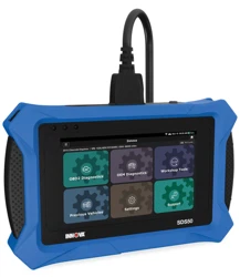
OE-Level Diagnostic Tablet
USER S MANUAL
i
WELCOME TO THE INNOVA FAMILY!
Hello...
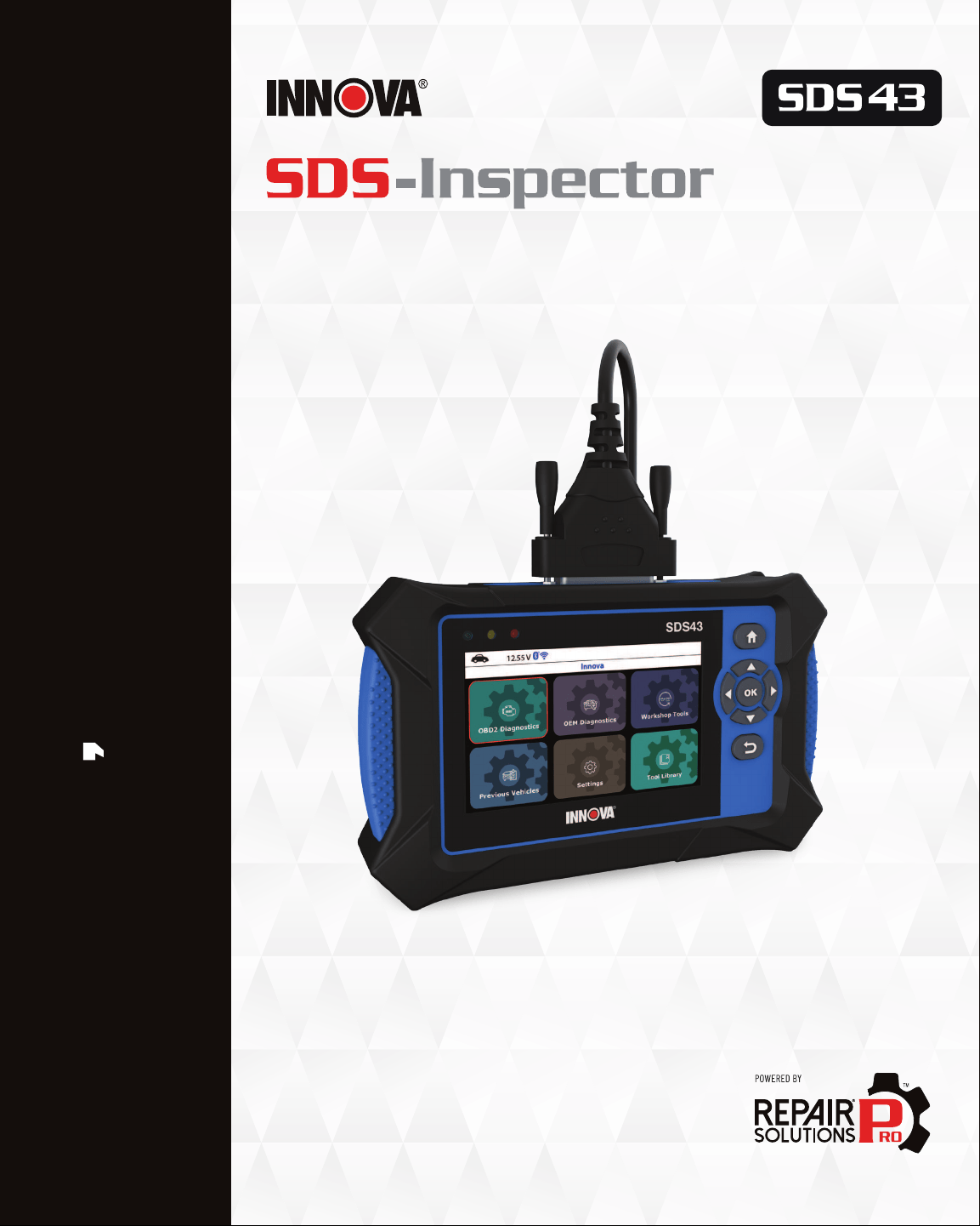
On behalf of everyone at INNOVA, we want to welcome you and thank you for purchasing the
INNOVA
®
SDS Inspector! Every automotive diagnostic scan tool we make includes tons of
pro-level features designed to help maximize, and simplify, your OBD2 diagnostic routine. In
this manual, we will guide you on how to access your tablet’s intuitive functions including:
Plus, gain the benet of having unlimited access to real world solutions on your mobile device:
Enjoy using your INNOVA SDS Tablet!
Yours sincerely,
The Innova Technical Team
P.S.: Connect with us to see what we’re up to...
RepairSolutionsPRO™ increases the power of your INNOVA
OBD2 diagnostic tablet by delivering the most complete
automotive repair database with veried xes from ASE
Certied Master Technicians. Get the right x and the right
parts instantly right on your SDS Tablet or mobile device.
; Check Engine Light Diagnostics
; OEM Network Scans
; Smog / Emissions Readiness
; Bi-Directional / Active Test
; Enhanced Data Stream for ECM (PCM),
TCM, ABS, SRS systems
; Code Severity Level Identier
; Battery / Charging System Test
; TPMS / Tire Pressure Readings
; Read Oil Life, Oil Level, Brake Pad
Life, Transmission Temperature
; Hybrid Battery Cell Voltage
Readings
; Workshop Tools (12 service resets
including Oil Maintenance Reset,
Electronic Parking Brake Reset,
ABS Bleeding, DPF Reset, etc.)
; OEM ECU Information
; And Much More...

ii
TABLE OF CONTENTS
LEGAL INFORMATION � � � � � � � � � � � � � � � � � � � � � � � � � � � � � � � 1
FCC Compliance Statement � � � � � � � � � � � � � � � � � � � � � � � � � � � � � � � � � � � � � � � � � � �1
Trademarks � � � � � � � � � � � � � � � � � � � � � � � � � � � � � � � � � � � � � � � � � � � � � � � � � � � � � �1
Patents � � � � � � � � � � � � � � � � � � � � � � � � � � � � � � � � � � � � � � � � � � � � � � � � � � � � � � � � � 2
Software Version� � � � � � � � � � � � � � � � � � � � � � � � � � � � � � � � � � � � � � � � � � � � � � � � � � 2
California Product Warnings � � � � � � � � � � � � � � � � � � � � � � � � � � � � � � � � � � � � � � � � � 2
SAFETY PRECAUTIONS � � � � � � � � � � � � � � � � � � � � � � � � � � � � � �3
Safety First! � � � � � � � � � � � � � � � � � � � � � � � � � � � � � � � � � � � � � � � � � � � � � � � � � � � � � 3
Safety Alert Icons � � � � � � � � � � � � � � � � � � � � � � � � � � � � � � � � � � � � � � � � � � � � � � � � � 4
INTRODUCTION � � � � � � � � � � � � � � � � � � � � � � � � � � � � � � � � � �5
Tablet Controls and Indicators� � � � � � � � � � � � � � � � � � � � � � � � � � � � � � � � � � � � � � � � 5
Tablet Display Functions � � � � � � � � � � � � � � � � � � � � � � � � � � � � � � � � � � � � � � � � � � � � 6
Technical Specications � � � � � � � � � � � � � � � � � � � � � � � � � � � � � � � � � � � � � � � � � � � � 7
The RepairSolutionsPRO™ App� � � � � � � � � � � � � � � � � � � � � � � � � � � � � � � � � � � � � � � � 8
The RSPRO APP Offers… � � � � � � � � � � � � � � � � � � � � � � � � � � � � � � � � � � � �8
Hardware Requirements � � � � � � � � � � � � � � � � � � � � � � � � � � � � � � � � � � � �8
Download the RSPRO App � � � � � � � � � � � � � � � � � � � � � � � � � � � � � � � � � � �8
Using the RepairSolutionsPRO App � � � � � � � � � � � � � � � � � � � � � � � � � � � � � �9
USING THE TABLET � � � � � � � � � � � � � � � � � � � � � � � � � � � � � � � 10
Home Screen� � � � � � � � � � � � � � � � � � � � � � � � � � � � � � � � � � � � � � � � � � � � � � � � � � � � �10
INITIAL TABLET SETUP (Personal Settings) � � � � � � � � � � � � � � � � � � � � � � � � � � � � � � �10
OBD2 Diagnostics � � � � � � � � � � � � � � � � � � � � � � � � � � � � � � � � � � � � � � � � � � � � � � � � � 11
I/M Readiness Status - $01, $41 � � � � � � � � � � � � � � � � � � � � � � � � � � � � � � � 12
Retrieving OBD2 Diagnostic Trouble Codes (DTCs) � � � � � � � � � � � � � � � � � � � � 12
Fix for DTCs � � � � � � � � � � � � � � � � � � � � � � � � � � � � � � � � � � � � � � � � � 16

iii
TABLE OF CONTENTS
OBD2 Report � � � � � � � � � � � � � � � � � � � � � � � � � � � � � � � � � � � � � � � � � 17
Erasing Diagnostic Trouble Codes (DTCs) - $04 � � � � � � � � � � � � � � � � � � � � � � � 19
Freeze Frame - $02 � � � � � � � � � � � � � � � � � � � � � � � � � � � � � � � � � � � � � 20
Live Data - $01 � � � � � � � � � � � � � � � � � � � � � � � � � � � � � � � � � � � � � � � � 20
Viewing Live Data .............................................................21
Customizing Live Data (PIDs) ................................................... 22
Record Live Data � � � � � � � � � � � � � � � � � � � � � � � � � � � � � � � � � � � � � � � 24
Record by DTC Trigger......................................................... 24
Record Manually.............................................................. 25
Playback Live Data � � � � � � � � � � � � � � � � � � � � � � � � � � � � � � � � � � � � � � 26
O2 Sensor Monitor - $05 � � � � � � � � � � � � � � � � � � � � � � � � � � � � � � � � � � � 28
OBD Monitor Test - $06 � � � � � � � � � � � � � � � � � � � � � � � � � � � � � � � � � � � � 28
Request Control On-Board System - $08 � � � � � � � � � � � � � � � � � � � � � � � � � � 30
Drive Cycle Procedures � � � � � � � � � � � � � � � � � � � � � � � � � � � � � � � � � � � 30
Viewing Vehicle Information - $09 � � � � � � � � � � � � � � � � � � � � � � � � � � � � � 31
Viewing Vehicle ID .............................................................31
Viewing Available Modules .....................................................32
Viewing In-Use Performance Tracking ...........................................32
OEM Diagnostics � � � � � � � � � � � � � � � � � � � � � � � � � � � � � � � � � � � � � � � � � � � � � � � � � 33
Perform a Scan - Scan All Systems � � � � � � � � � � � � � � � � � � � � � � � � � � � � � 33
Reading DTCs for a Selected Module . . . . . . . . . . . . . . . . . . . . . . . . . . . . . . . . . . . . . . . . . . . . . 34
Erasing DTCs for a Selected Module .............................................34
Viewing Live Data for a Selected Module..........................................35
Perform Active Test for a Selected Module � � � � � � � � � � � � � � � � � � � � � � � � � 35
Chrysler Active Tests..........................................................35
NVLD Evaporative Vent Valve Solenoid Control State .................................36
GM Active Tests ..............................................................36
Air Pump Relay Test ............................................................36
Cooling Fan Test ...............................................................37

iv
EVAP Purge Solenoid Test .......................................................37
EVAP Vent Solenoid Test ........................................................37
Fuel Pump Relay Test ..........................................................38
Ford Active Tests .............................................................38
Spark Advance Test ............................................................38
Gear Commanded by Output State Control Test......................................39
One-Touch Start Status Test .....................................................39
(EVAP) Vapor Blocking Valve Test .................................................40
Output State Control of Torque Converter Test ......................................40
Fan Speed Desired Test .........................................................40
Fuel Pump Test ............................................................... 41
Injector Disable Test............................................................ 41
Hyundai Active Tests ..........................................................41
Check Engine Lamp (MIL) Test....................................................42
Electronic Waste Gate Valve (Turbo Only) Test ......................................42
Variable Intake Solenoid (Option) Test .............................................43
Nissan Active Tests ..........................................................43
Fan Duty Control Test ..........................................................43
Purge Vol Control Valve Test .....................................................44
Vent Control Valve Test .........................................................44
Toyota Active Tests ........................................................... 44
EGR Cut VSV Test ..............................................................45
EGR Step Position / System Test .................................................45
Inspection Mode Test ..........................................................46
Cranking Request Test .........................................................46
PWM Output Test ..............................................................46
Cooling Fan Test ..............................................................47
OFF Ave Cg Relay Test ..........................................................47
Honda Active Tests ...........................................................48
TABLE OF CONTENTS

v
A/C Clutch Manual Operation Test .................................................48
CRK Pattern Clear ..............................................................48
Reading ECU Information........................................................49
Perform a Scan for Individual Modules � � � � � � � � � � � � � � � � � � � � � � � � � � � 49
Vehicle Inspection � � � � � � � � � � � � � � � � � � � � � � � � � � � � � � � � � � � � � � 50
DTC Detail – to view Denitions and status DTCs of all systems. ......................50
Workshop Tools� � � � � � � � � � � � � � � � � � � � � � � � � � � � � � � � � � � � � � � � � � � � � � � � � � �51
Oil Maintenance Reset � � � � � � � � � � � � � � � � � � � � � � � � � � � � � � � � � � � � 51
Battery Reset � � � � � � � � � � � � � � � � � � � � � � � � � � � � � � � � � � � � � � � � 52
Battery Initialization (Audi, BMW, Ford, Volkswagen, Volvo) � � � � � � � � � � � � � � � � 53
Steering Angle Sensor (SAS) Calibration � � � � � � � � � � � � � � � � � � � � � � � � � � 54
Electronic Parking Brake (EPB) Reset � � � � � � � � � � � � � � � � � � � � � � � � � � � � 54
DPF Reset (
Except Chrysler, General Motors, Nissan, and Volkswagen) � � � � � � � � � � 55
DPF Reset (
Chrysler) � � � � � � � � � � � � � � � � � � � � � � � � � � � � � � � � � � � � 56
DPF Reset (
General Motors) � � � � � � � � � � � � � � � � � � � � � � � � � � � � � � � � � 56
DPF Reset (
Nissan) � � � � � � � � � � � � � � � � � � � � � � � � � � � � � � � � � � � � � 56
DPF Reset (
Volkswagen) � � � � � � � � � � � � � � � � � � � � � � � � � � � � � � � � � � � 57
ABS Bleeding � � � � � � � � � � � � � � � � � � � � � � � � � � � � � � � � � � � � � � � � � 57
EV/HEV/PHEV Battery Health � � � � � � � � � � � � � � � � � � � � � � � � � � � � � � � � 58
Battery / Alternator Test � � � � � � � � � � � � � � � � � � � � � � � � � � � � � � � � � � � 58
Perform a Battery Check Only ..................................................58
View Battery Live Data ........................................................ 59
Perform a Charging System Check ..............................................60
View Alternator Live Data ......................................................60
Previous Vehicles � � � � � � � � � � � � � � � � � � � � � � � � � � � � � � � � � � � � � � � � � � � � � � � � �61
Settings � � � � � � � � � � � � � � � � � � � � � � � � � � � � � � � � � � � � � � � � � � � � � � � � � � � � � � � 62
Vehicle Inspection Setup � � � � � � � � � � � � � � � � � � � � � � � � � � � � � � � � � � 62
AutoLink Setting � � � � � � � � � � � � � � � � � � � � � � � � � � � � � � � � � � � � � � � 63
TABLE OF CONTENTS

vi
Wi-Fi Setting � � � � � � � � � � � � � � � � � � � � � � � � � � � � � � � � � � � � � � � � � 63
Adjusting Display Brightness � � � � � � � � � � � � � � � � � � � � � � � � � � � � � � � � 64
Enabling/Disabling the Audible Tone � � � � � � � � � � � � � � � � � � � � � � � � � � � � 64
Selecting the Display Language � � � � � � � � � � � � � � � � � � � � � � � � � � � � � � � 64
Setting the Unit of Measurement � � � � � � � � � � � � � � � � � � � � � � � � � � � � � � 65
Smog Check or I/M Program Location � � � � � � � � � � � � � � � � � � � � � � � � � � � � 65
Viewing the App QR Code - RepairSolutionsPRO™ � � � � � � � � � � � � � � � � � � � � � 65
Setting the QR RepairSolutionsPRO App Mode � � � � � � � � � � � � � � � � � � � � � � � 65
Viewing the Version Information � � � � � � � � � � � � � � � � � � � � � � � � � � � � � � 65
Updating the Tablet � � � � � � � � � � � � � � � � � � � � � � � � � � � � � � � � � � � � � 66
Tool Library � � � � � � � � � � � � � � � � � � � � � � � � � � � � � � � � � � � � � � � � � � � � � � � � � � � � 67
Icon Denition � � � � � � � � � � � � � � � � � � � � � � � � � � � � � � � � � � � � � � � � 67
DTC Library � � � � � � � � � � � � � � � � � � � � � � � � � � � � � � � � � � � � � � � � � � 67
Smog Check or I/M Program LED Denitions � � � � � � � � � � � � � � � � � � � � � � � � 68
Using the DLC Locator � � � � � � � � � � � � � � � � � � � � � � � � � � � � � � � � � � � � 68
Icon Monitor Status � � � � � � � � � � � � � � � � � � � � � � � � � � � � � � � � � � � � � 69
WARRANTY+ CUSTOMER SERVICE � � � � � � � � � � � � � � � � � � � � � � � 70
Limited Warranty � � � � � � � � � � � � � � � � � � � � � � � � � � � � � � � � � � � � � � � � � � � � � � � � 70
Customer Service � � � � � � � � � � � � � � � � � � � � � � � � � � � � � � � � � � � � � � � � � � � � � � � � 70
GLOSSARY � � � � � � � � � � � � � � � � � � � � � � � � � � � � � � � � � � � 71
OBD2 Terminology � � � � � � � � � � � � � � � � � � � � � � � � � � � � � � � � � � � � � � � � � � � � � � � � �71
OBD2 Monitors� � � � � � � � � � � � � � � � � � � � � � � � � � � � � � � � � � � � � � � � � � � � � � � � � � � 72
Continuous Monitors � � � � � � � � � � � � � � � � � � � � � � � � � � � � � � � � � � � � � 72
Non-Continuous Monitors � � � � � � � � � � � � � � � � � � � � � � � � � � � � � � � � � � 73
Additional Terminology + Acronyms � � � � � � � � � � � � � � � � � � � � � � � � � � � � � � � � � � 73
TABLE OF CONTENTS

LEGAL INFORMATION
FCC Compliance Statement
LEGAL INFORMATION
FCC COMPLIANCE STATEMENT
This equipment has been tested and found to comply with the limits for a Class B digital device, pursuant to part 15 of
the FCC Rules. These limits are designed to provide reasonable protection against harmful interference in a residential
installation. This equipment generates, uses and can radiate radio frequency energy and, if not installed and used
in accordance with the instructions, may cause harmful interference to radio communications. However, there is no
guarantee that interference will not occur in a particular installation. If this equipment does cause harmful interference
to radio or television reception, which can be determined by turning the equipment off and on, the user is encouraged
to try to correct the interference by one or more of the following measures:
n Reorient or relocate the receiving antenna.
n Increase the separation between the equipment and receiver.
n Connect the equipment into an outlet on a circuit different from that to which the receiver is
connected.
n Consult the dealer or an experienced radio/TV technician for help.
Changes or modications not expressly approved by the party responsible for compliance could void the user’s
authority to operate the equipment.
FCC ID: 2AC7Z-ESPWR00M32D
FCC RF Radiation Exposure Statement
n The transmitters within this device must not be co-located or operating in conjunction with any
other antenna or transmitter.
n This equipment complies with IC radiation exposure limits set forth for an uncontrolled
environment. End users must follow the specic operating instructions for satisfying RF
exposure compliance. To maintain with IC RF exposure compliance requirements please follow
operation instruction as documented in this manual.
TRADEMARKS
Title, ownership rights, and intellectual property rights in the Products and Services shall remain in Innova and/or its
licensors and other suppliers. Licensee and End Users acknowledge such ownership, condential information, and
intellectual property rights and will not take any action to jeopardize, limit or interfere in any manner with Innova’s or
its licensors’ or other suppliers’ ownership of or rights with respect to the Products and Services. The Products and
Services may be protected by Patent, Trademark, Copyright and/or other intellectual property laws and by international
treaties. All trademarks used in connection with the Products and Services are owned by Innova, its afliates or its
licensors and other suppliers, and no license to use any such trademarks is provided hereunder. Licensee and End
Users agree that Innova may use in any manner and without limitation all comments, suggestions, complaints and other
feedback Licensee and End Users provide relating to the Products and Services. For more information and current
1
2
LEGAL INFORMATION
Patents
listing of trademarks, please visit https://www.innova.com/pages/trademarks.
PATENTS
Innova Electronics Corp. protects its intellectual property with numerous U.S. patents, which were used to research,
design and manufacture this product. Please visit
https://www.innova.com/pages/patents for additional information.
SOFTWARE VERSION
Please note that the images and functions on this manual may differ based on the current Firmware Version (FW)
and Software Version you have. To check your tablet’s current version and to check for updates, please see the
SETTINGS tab under the Version Information section. [
See page 65]
CALIFORNIA PRODUCT WARNINGS

SAFETY PRECAUTIONS
Safety First!
SAFETY PRECAUTIONS
SAFETY FIRST!
It is important that every user utilizing this product read all instructions and warnings included within this manual
to ensure your safety, the safety of others, and to prevent damage to this product & vehicles being diagnosed and
repaired. This manual describes common test procedures used by experienced service technicians. It is inferred that
the user has a good understanding of vehicle systems before using this product.
Many test procedures require precautions to avoid accidents that can result in personal injury, and/or damage to
your vehicle or test equipment. At a minimum, the following safety standards should be followed whenever using this
product, or whenever working on a vehicle.
When an engine is running, it produces carbon monoxide, a toxic and poisonous gas. To
prevent serious injury or death from carbon monoxide poisoning, operate the vehicle ONLY in
a well-ventilated area.
To protect your eyes from propelled objects as well as hot or caustic liquids, always wear
approved safety eye protection.
When an engine is running, many parts (such as the coolant fan, pulleys, fan belt etc.) turn at
high speed. To avoid serious injury, always be aware of moving parts. Keep a safe distance
from these parts as well as other potentially moving objects.
Engine parts become very hot when the engine is running. To prevent severe burns, avoid
contact with hot engine parts.
Before starting an engine for testing or troubleshooting, make sure the parking brake is
engaged. Put the transmission in park (for automatic transmission) or neutral (for manual
transmission). Block the drive wheels with suitable tire blocks.
Connecting or disconnecting test equipment when the ignition is ON can damage test equipment
and the vehicle’s electronic components. Turn the ignition OFF before connecting the tablet
to or disconnecting the tablet from the vehicle’s Data Link Connector (DLC).
To prevent damage to the on-board computer when taking vehicle electrical measurements,
always use a digital multimeter with at least 10 Megohms of impedance.
Fuel and battery vapors are highly ammable. To prevent an explosion, keep all sparks, heated
items, and open ames away from the battery and fuel vapors. DO NOT SMOKE NEAR THE
VEHICLE DURING TESTING.
Don’t wear loose clothing or jewelry when working on an engine. Loose clothing can
become caught in the fan, pulleys, belts, etc. Jewelry is highly conductive and can cause a
severe burn if it makes contact between a power source and ground.
3
4
SAFETY PRECAUTIONS
Safety Alert Icons
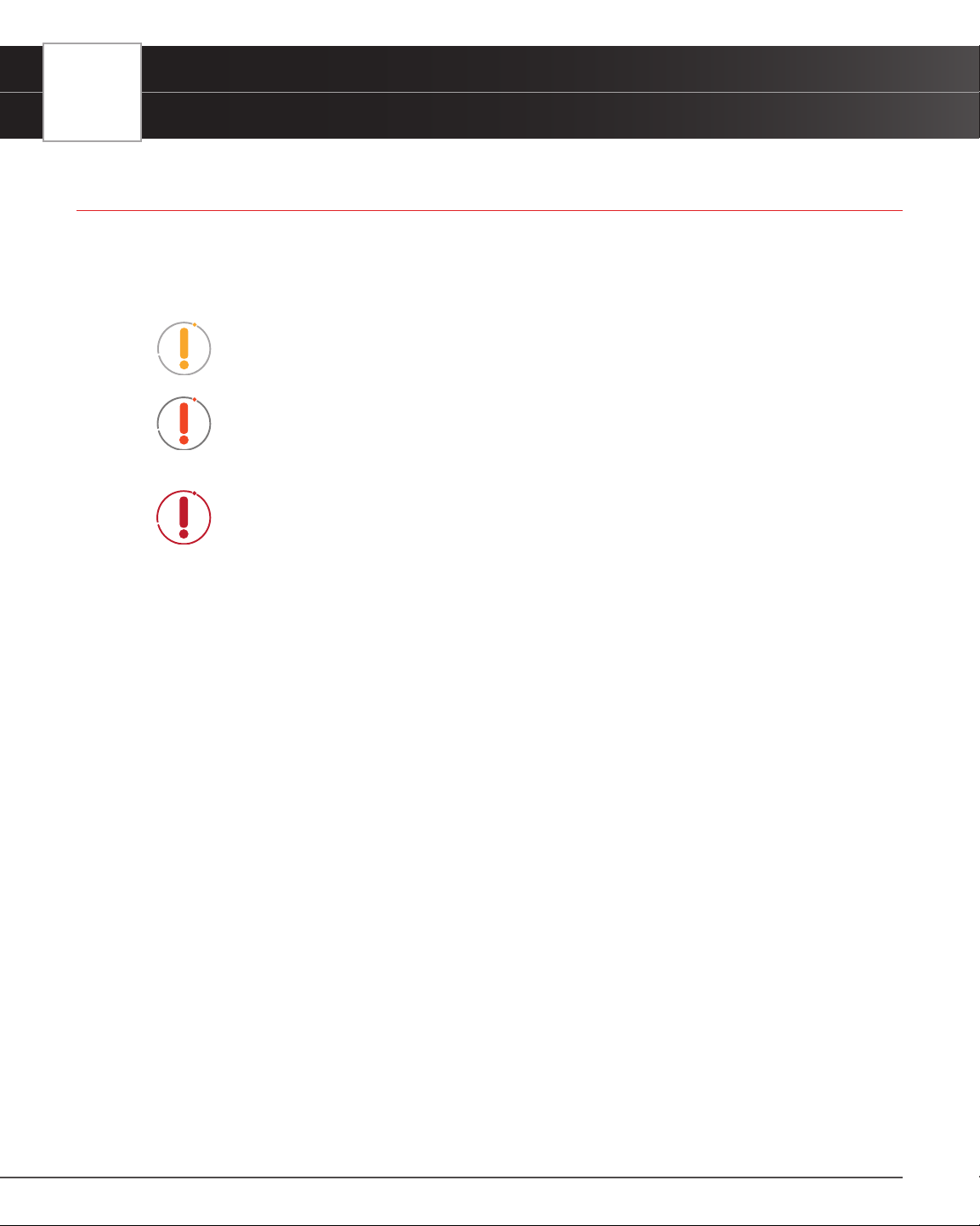
SAFETY ALERT ICONS
As you read this manual, color-coded icons are used throughout to identify safety alerts and warnings. These are
provided to help prevent serious injury to you, injury to bystanders, and damage to property or equipment. They are
characterized as follows:
Yellow Icon – Provides a ”NOTE:“ statement to offer special information
or tip on what is being instructed.
Orange Icon – Potential hazardous situation. Provides a “
WARNING:“
statement on how to proceed to avoid serious injury to the user,
bystanders, and/or equipment.
Red Icon – Imminent hazardous situation. Provides an immediate
“
DANGER:“ alert on what must be done to prevent serious injury or death
to the user or bystanders.
INTRODUCTION
Tablet Controls and Indicators
INTRODUCTION
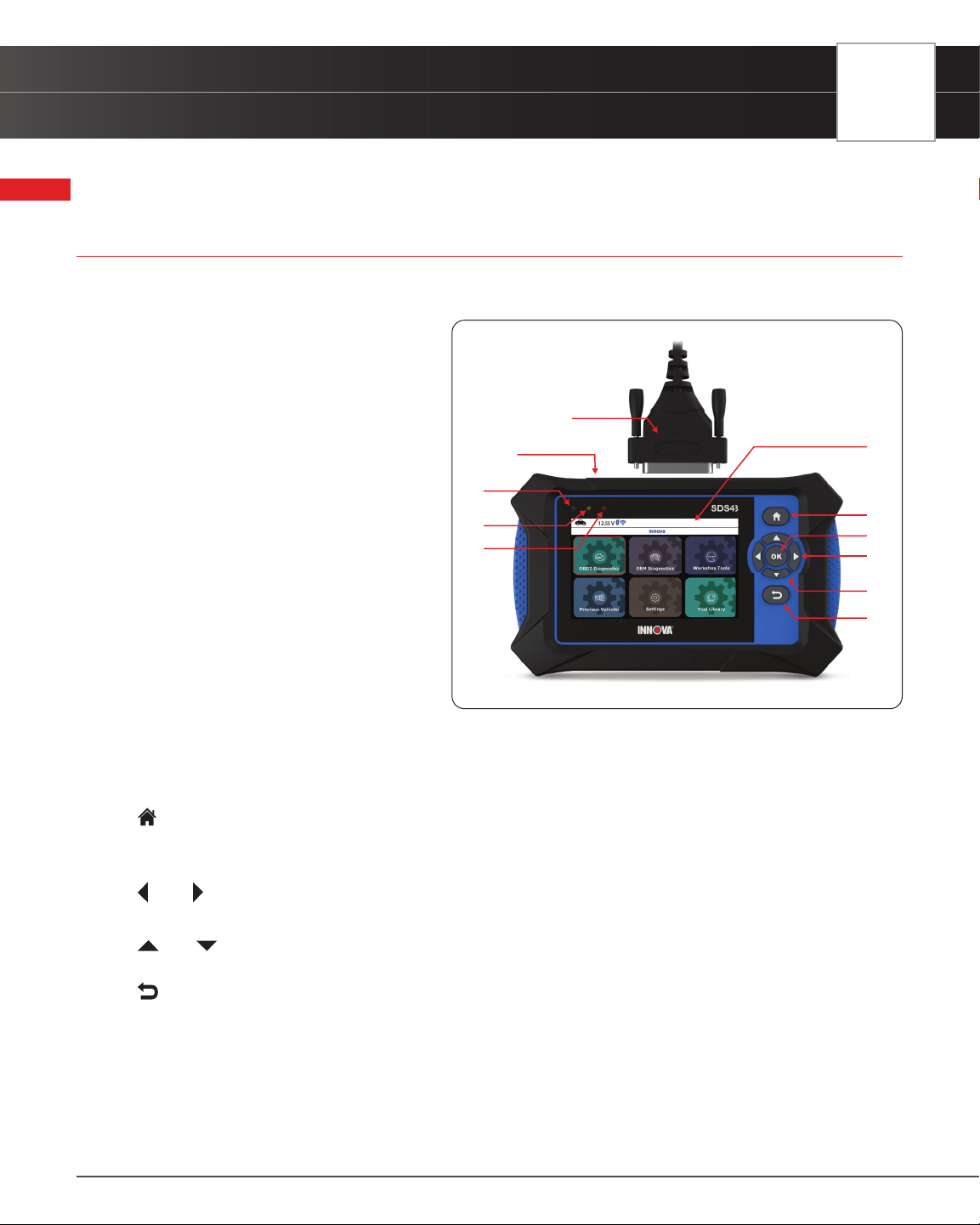
TABLET CONTROLS AND INDICATORS
See Figure 1 for the locations of items 1 through 11, below.
1. 4.3-inch LCD Screen - Color LCD display
shows menus and sub-menus, test
results, tablet functions and vehicle status
information.
2. Diagnostic Port - Connects the Tablet to
the vehicle’s Data Link Connector (DLC).
3. USB Port - Allows connection to a PC
using a standard USB cable.
4. GREEN LED - Indicates that all engine
systems are running normally, and
all emission monitors are active and
performing their diagnostic testing. The
Malfunction Indicator “Check Engine”
Lamp on the vehicle’s instrument panel is
off.
5. YELLOW LED - Indicates there is a
possible problem in one or more of the
vehicle’s systems. Either a “Pending” DTC
is present and/or some of the vehicle’s
emission monitors have not run their diagnostic testing.
6. RED LED - Indicates there is a problem in one or more of the vehicle’s systems. The Malfunction Indicator “Check
Engine” Lamp on the vehicle’s instrument panel is on.
7.
Home Button - Press from any screen to return back to the Home screen (except the screens in Active Test
and services reset function).
8. OK Button - Conrms the selected option or value.
9.
Left / Right Button - Moves selection cursor left or right, or helps scroll through pages when more than one
page is displayed.
10.
Up / Down Button - When in MENU mode, scrolls Up/Down through the menu options. When LINKED to
a vehicle, scrolls Up/Down through the current display screen to display additional data.
11.
Back Button - Exits the current function or returns to the previous screen.
Figure 1� Controls and Indicators
1
2
3
4
5
6
7
9
10
11
8
5
6
INTRODUCTION
Tablet Display Functions
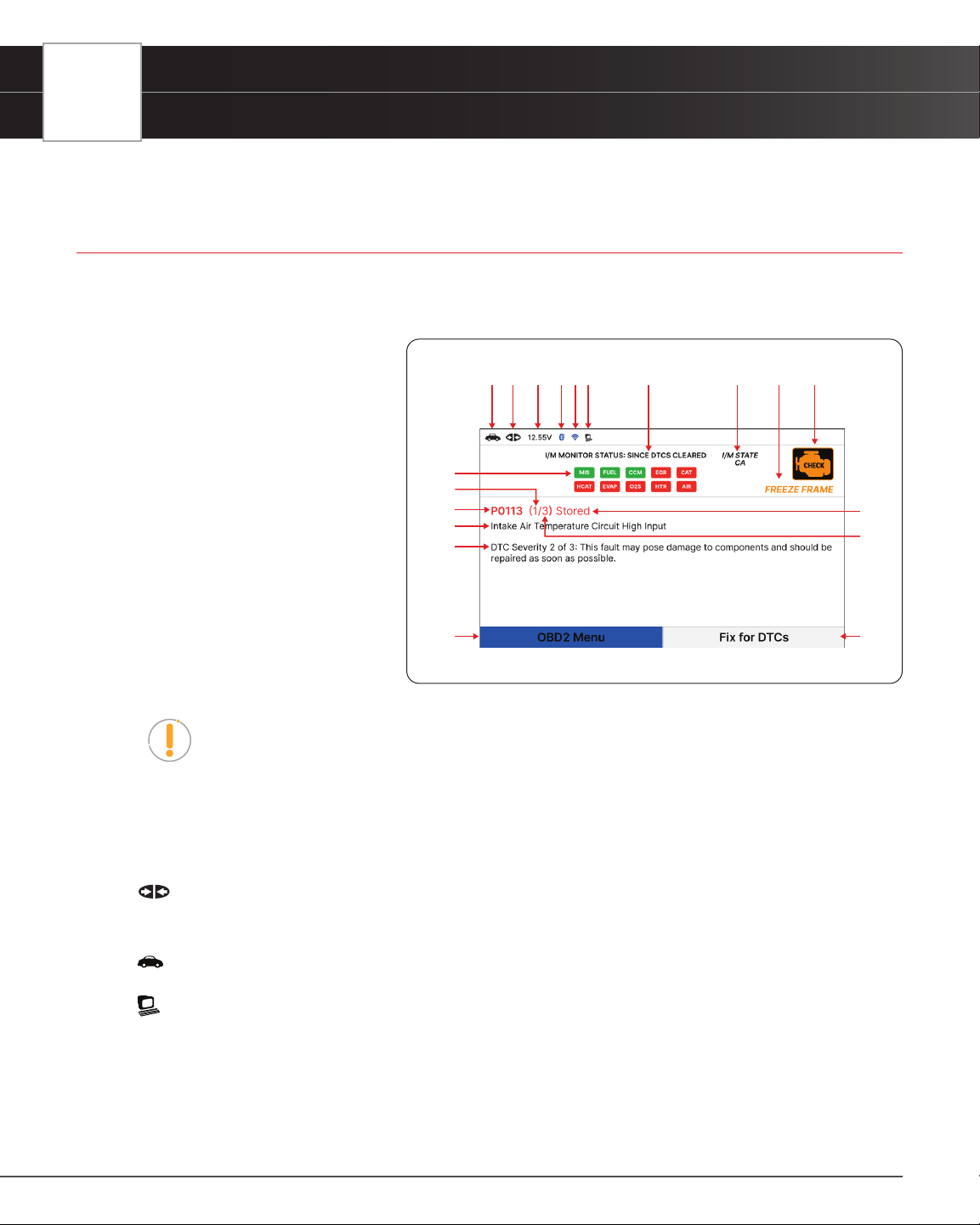
TABLET DISPLAY FUNCTIONS
See Figure 2 for the locations of items 1 through 19 below.
1. I/M MONITOR STATUS: SINCE DTCs CLEARED eld - Identies the I/M Monitor status area.
2. Monitor icons - Indicate which
Monitors are supported by the vehicle
under test, and whether or not the
associated Monitor has completed
its diagnostic testing (Monitor status).
When a Monitor icon is solid green,
it indicates that the Monitor has
completed both Since DTCs Cleared
and This Drive Cycle. When a Monitor
icon is ashing red, it indicates that
the Monitor has not completed testing
Since DTCs Cleared. When a Monitor
is Green-Gray, it indicates that the
monitor has not completed testing This
Drive Cycle. When a Monitor is Red-
Gray, it indicates that the monitor has
been disabled This Drive Cycle.
NOTE: The I/M Monitor Status icons are associated with INSPECTION and
MAINTENANCE (I/M) READINESS STATUS. Some states require that all vehicle
Monitors have run and completed their diagnostic testing before a vehicle can be
tested for Emissions (Smog Check). A maximum of fteen Monitors are used on
OBD2 systems. Not all vehicles support all fteen Monitors. When the Tablet is linked
to a vehicle, only the icons for Monitors that are supported by the vehicle under test
are visible on the display.
3.
Link Icon - Indicates whether or not the Tablet is communicating (linked) with the vehicle’s on-board
computers. When visible, the Tablet is communicating with the computers. If the Link icon is not visible, the Tablet
is not communicating with the vehicle’s computers.
4.
Vehicle Icon - Indicates whether or not the Tablet is being properly powered through the vehicle’s Data Link
Connector (DLC). A visible icon indicates that the Tablet is being powered through the vehicle’s DLC connector.
5.
Computer Icon – When visible, indicates the Tablet is linked to a personal computer.
6. DTC Display Area - Displays the Diagnostic Trouble Code (DTC) number. Each fault is assigned a code number
that is specic to that fault.
7. Code Type – Indicates the type of code being displayed: Stored, Pending, Permanent.
8. Code Number Sequence - The Tablet assigns a sequence number to each DTC that is present in the computer’s
memory, starting with “1”. This helps keep track of the number of DTCs present in the computer’s memory. Code
Figure 2� Tablet Display Functions
1
2
345
6
7
9
10
11
12 13
1415161718
8
19
INTRODUCTION
Technical Specications
number ”1” is always the highest priority code and the one for which “Freeze Frame” data has been stored.
NOTE: If “1” is a “Pending” code, there may or may not be “Freeze Frame” data
stored in memory.
9. Code Enumerator - Indicates the total number of codes retrieved from the vehicle’s computer.
10. Test Data Display Area – Displays DTC denitions, Freeze Frame data and other pertinent test information
messages.
11. Severity – Indicates the level of severity for the priority code (code number “1”), as follows:
[1] This fault typically does not cause damage to components and should be serviced when convenient.
[2] This fault may pose damage to components and should be repaired as soon as possible.
[3] This fault will cause damage to components and should be repaired immediately.
12. OBD2 Menu – Displays menu to perform the 10 modes of OBD2 functions.
13. Fix for DTCs – Displays the veried x for retrieved DTCs.
14.
MIL Icon - Indicates the status of the Malfunction Indicator Lamp (MIL). The MIL icon is visible only when a
DTC has commanded the MIL on the vehicle’s dashboard to light.
15. FREEZE FRAME Icon - Indicates that there is Freeze Frame data stored in the vehicle’s computer memory
(Captured when Priority Code was set / Code #1).
16. I/M STATE – Displays acronym of I/M program location.
17.
Wi-Fi Icon – When OFF, indicates there is no Wi-Fi connection.
18.
Bluetooth Icon – Indicates communication status with a compatible INNOVA
®
mobile application. A solid
blue icon indicates an active Bluetooth connection has been established.
19. 12.55V – Displays the vehicle’s current battery voltage.
TECHNICAL SPECIFICATIONS
The following table provides the tablet’s current technical specications*:
Display Type
4.3 Inch Panel
J1962 DLC Cable
6-foot Detachable 16-pin OBDII Compliant Connector
Wi-Fi
802.11b/g/n
Operating Temperature
23ºF to 113ºF (-5ºC to 45ºC)
Memory
4GB Memory
7
8
INTRODUCTION
The RepairSolutionsPRO™ App
Tablet Case
Rugged ABS Shock & Drop Resistant
Included Accessories
Molded Storage Case, Quick Start Guide, USB Cable
*Manufacturer reserves the right to change technical specications at any time.
THE RepairSolutionsPRO™ APP
Innova’s RepairSolutionsPRO (RSPRO) app is a web-based service created to assist Professional technicians
simplify and augment their vehicle diagnostic process.
In essence, it helps you decode the diagnostic data collected by your
INNOVA
®
OBD2 Tablet to arrive at a most likely x. At its core, the app uses
a database of millions of real-world veried xes–collected over the last 25
years by ASE Master Technicians across the U.S.– that is cross-referenced
to your specic vehicle’s problem to instantly arrive at a veried x. Think of it
as a second opinion from your most trusted peers to help you diagnose and
repair more vehicles.
THE RSPRO APP OFFERS…
n Veried Fixes – Find the most likely xes reported and veried by ASE Technicians for the
retrieved DTCs. Plus, quickly purchase the exact parts you need right from the app.
n Predicted Repairs – With millions of veried repair solutions, get a statistical probability of what
repairs the vehicle may need within the next 12 months.
n TSBs & Recalls – Learn if there are any special NHTSA safety recalls or Technical Service
Bulletins (TSBs) issued by the vehicle’s manufacturer.
n Upcoming Maintenance – View the vehicle manufacturer’s recommended maintenance
intervals. Plus, conveniently order the correct maintenance parts right from the app.
n And much more...
HARDWARE REQUIREMENTS
n Innova OBD2 Tablet with Bluetooth/Wi-Fi connectivity.
n Android or iOS Mobile Device.
DOWNLOAD THE RSPRO APP
n Available for Apple iOS & Android Devices (Scan QR Code)

INTRODUCTION
The RepairSolutionsPRO™ App
USING THE RepairSolutionsPRO APP
1. Retrieve your vehicle’s diagnostic data. [See page 12]
2. Download and install the RSPRO app (see above).
3. Launch the app and log in to your account.
n If you have not yet established an account, you must register for a FREE account before
proceeding.
4. Follow the screen prompts to pair your INNOVA Tablet. Be sure your mobile device is connected to an available
Wi-Fi network.
n Begin the pairing process by selecting your handheld tablet from the list.
NOTE: The RSPRO app can only store up to two Wi-Fi congurations.
5. Once paired, the data from your tablet is automatically transferred to the app to create a report.
NOTE: If the data does not automatically transfer, simply keep the app and tablet
paired and scan your vehicle again.
9
10
USING THE TABLET
Home Screen
USING THE TABLET
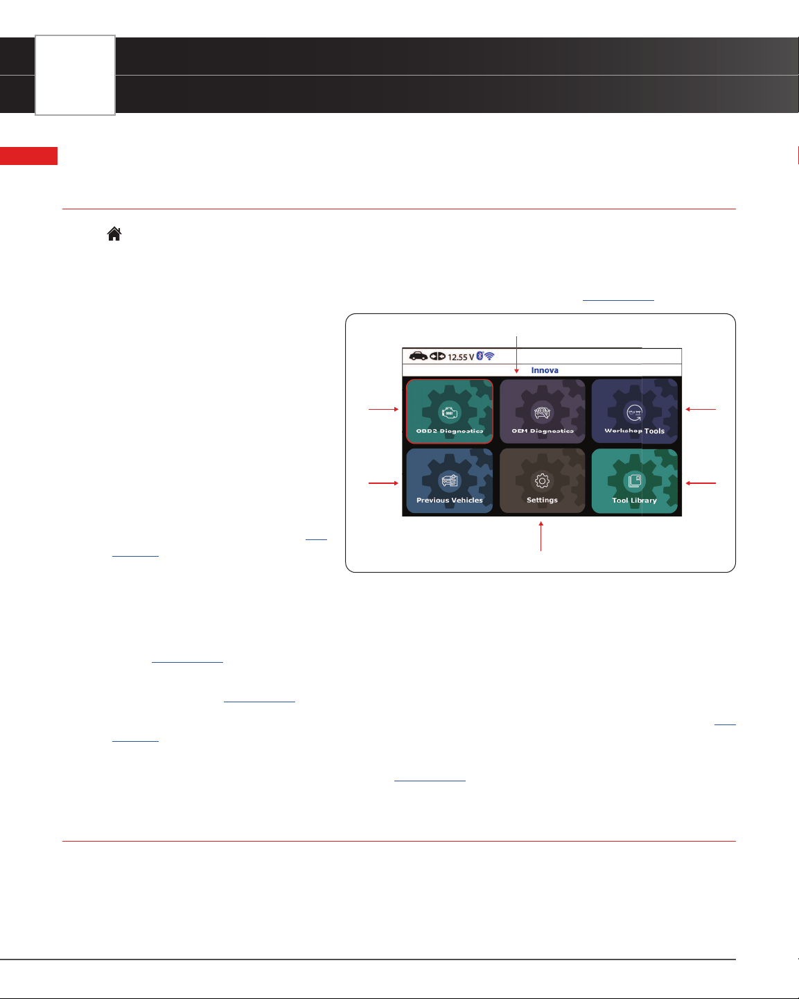
HOME SCREEN
The Home Screen provides access to all the tablet’s primary functions.
See Figure 3 for the explanation of items 1 through 6, below:
1. OBD2 Diagnostics Tab – Use to perform OBD2 menu, display 10 modes of OBD2. [
See page 11]
2. OEM Diagnostics Tab – Provides
enhanced OEM level diagnostics that
are not available over generic OBD2.
Access ABS, Airbag, Transmission,
Tire Pressure, Battery, and all modules
to view and erase their DTCs. Perform
bi-directional tests on fuel pump,
injectors, ignition coils, and much
more. Plus, get access to hundreds
of additional parameters that you
can view in real-time. Also provide
the Vehicle Inspection that show
Diagnostic Report, Customer Report
and Collision Industry Report. [
See
page 33
]
3. Workshop Tools Tab – Perform several OEM services, including Vehicle Inspection, Oil Maintenance Reset,
Battery Reset, Battery Initialization, EV/HEV/PHEV Battery Health, Battery/Alternator Test, Electronic Parking
Brake Reset, etc. Access dealership level relearn procedures to complete repairs or maintenance and much
more. [
See page 51]
4. Previous Vehicles Tab – Access and view reports for the 30 previous tested vehicles, including pre-recorded
Live Data streams. [
See page 61]
5. Settings Tab – Setup your tablet’s settings, including Wi-Fi, update software, and other personal settings. [
See
page 62
]
6. Tool Library Tab – Access the tablet’s tool library for DTC and tool icon denitions, Smog Check or I/M Program
LED Denition, DLC Locator, Monitor Icon Status. [
See page 67]
INITIAL TABLET SETUP (Personal Settings)
The rst time the Scan Tool is connected to a vehicle, it is necessary to complete your setup by performing the following
steps:
1. Select the desired display language (English, Spanish, French) and press OK.
Figure 3� Home Screen
1
2
3
4
5
6
USING THE TABLET
OBD2 Diagnostics
2. Select the desired unit of measurement (Standard or Metric) and press OK.
3. Select the preferred Smog Check or I/M Program Location and press OK.
4. The next screen displays the Smog Check or I/M Program LED Denition. Press OK to continue.
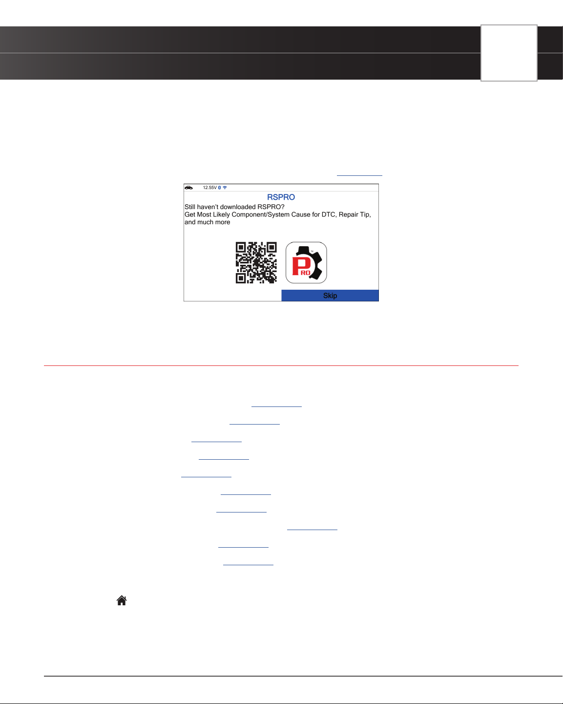
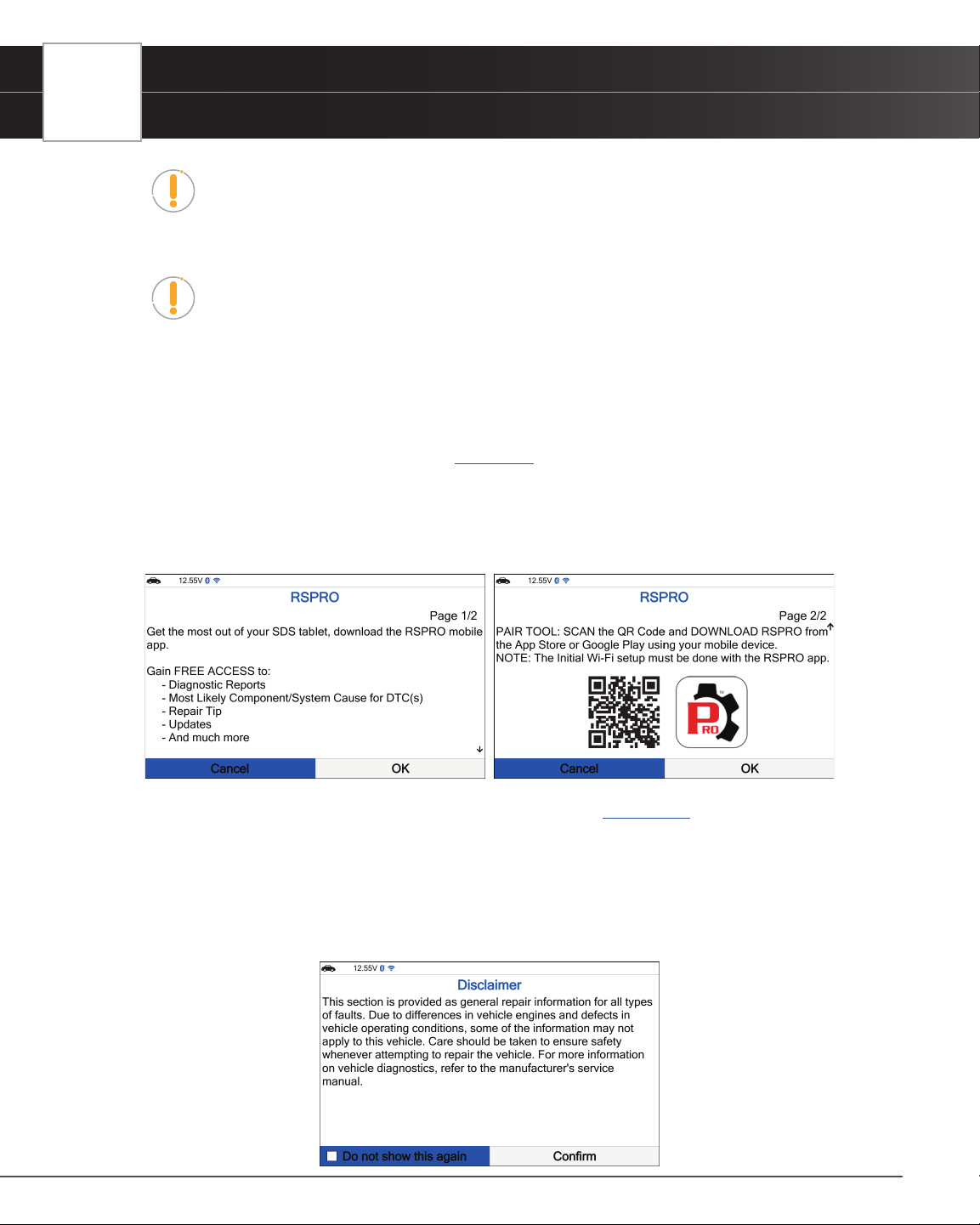
5. In this next screen, a QR code to RepairSolutionsPRO (RSPRO) is provided. Using any mobile device, scan the
code to download and install the free RSPRO app. The app offers additional information including Most Likely
Component/System Cause for DTC, Repair Tip, and much more. [
See page 8]
6. Enjoy your INNOVA Smart Diagnostic System!
OBD2 DIAGNOSTICS
The OBD2 Diagnostic provides access all 10 modes of OBD2. The following functions are available:
I/M Readiness Status – $01, $41 [See page 12]
Read DTCs - $03, $07, $0A [See page 12]
Erase DTCs - $04 [See page 19]
Freeze Frame - $02 [See page 20]
Live Data - $01 [See page 20]
O2 Sensor Monitor - $05 [See page 28]
OBD Monitor Test - $06 [See page 28]
Request Control On-Board System - $08 [See page 30]
Drive Cycle Procedures [See page 30]
Vehicle Information - $09 [See page 31]
There are two main ways to access OBD2 Diagnostic functions:
1. From the
Home Screen, select OBD2 Diagnostics and press the OK button.
2. From the OBD2 Control Display screen, select OBD2 Menu and press the OK button.
11
12
USING THE TABLET
OBD2 Diagnostics
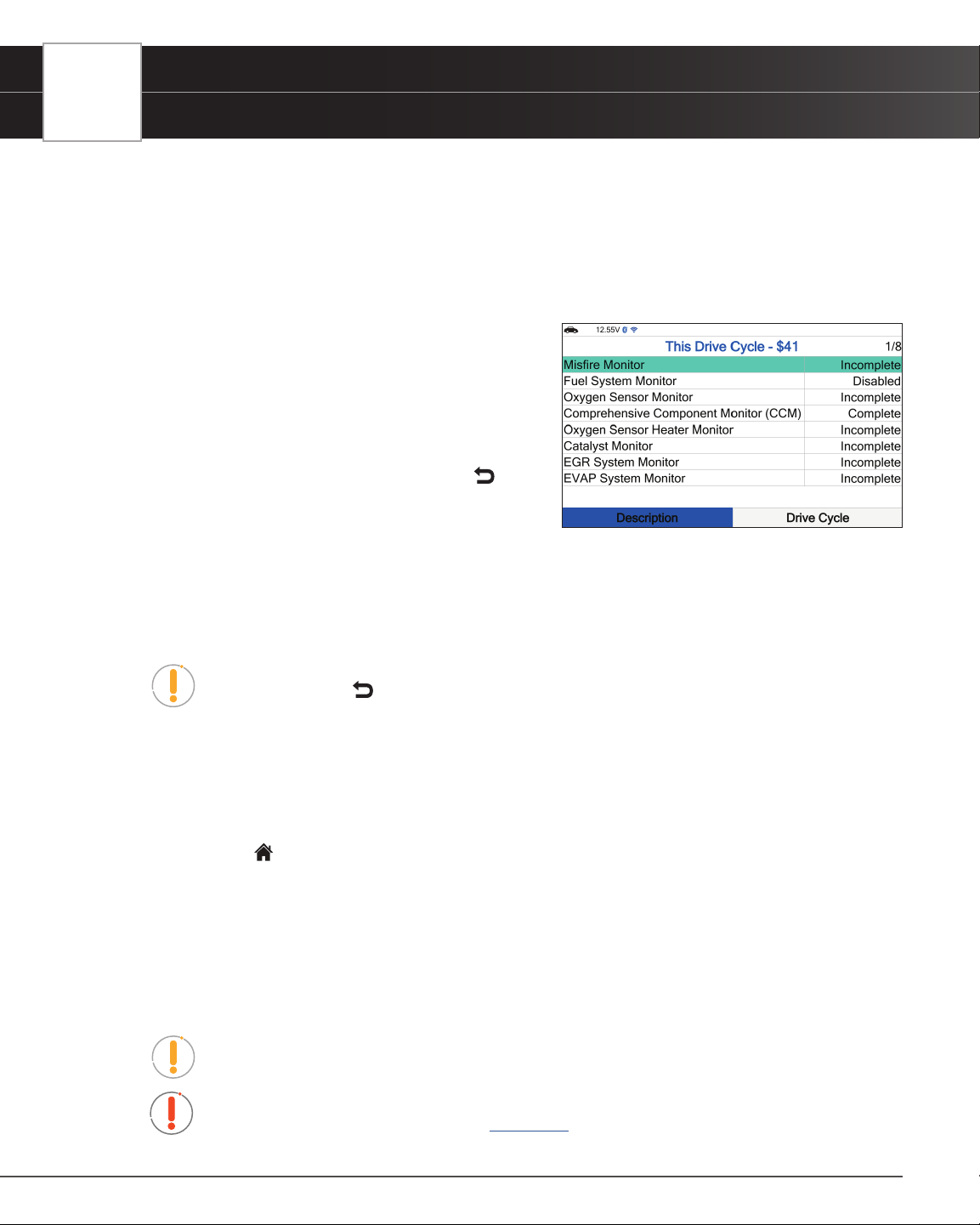
I/M READINESS STATUS - $01, $41
A Drive Cycle for a Monitor requires that the vehicle is driven in such a way that all the required “Enabling Criteria”
for the Monitor to run and complete its diagnostic testing are met. You can use the Tablet to view the Drive Cycle
Procedures for a selected Monitor. You can also view a description of a selected Monitor.
1. From the OBD2 Menu, select I/M Readiness Status - $01, $41, then press OK button.
2. A “One moment please. . .” message displays, followed
by a selection dialog. Select Since DTCs Cleared -
$01 or This Drive Cycle - $41 as appropriate. Press
OK to continue.
n If the vehicle under test does not support Since
DTCs Cleared - $01 or This Drive Cycle - $41, a
warning message displays “This vehicle does not
support this monitor type.” Press the
Back
button to return to the previous dialog.
3. The Select Monitor screen displays listing all Monitors
supported by the vehicle.
4. To view a Monitor description, select the desired Monitor, then choose Description.
n A description for the selected Monitor displays.
5. To view Drive Cycle Procedures for a Monitor, select the desired Monitor, then choose Drive Cycle.
NOTE: If Drive Cycle Procedures are not available for the vehicle, an advisory
message show. Press
Back to return to the OBD2 Menu.
n The Drive Cycle Procedures screen for the Monitor display.
6. The Drive Cycle Procedure screen shows the specic set of operating procedures that ensure the vehicle is
driven in such a way that all the required “Enabling Criteria” for the Monitor to run and complete its diagnostic
testing are met.
7. When you are nished viewing the Drive Cycle Procedures, choose Other Monitors to view other monitors
or press the
Home button to return to the Home Screen.
RETRIEVING OBD2 DIAGNOSTIC TROUBLE CODES (DTCs)
Never replace a part based only on the DTC denition. Each DTC has a set of testing procedures, instructions
and ow charts that must be followed to conrm the location of the problem. This information is found in the
vehicle’s service manual. Always refer to the vehicle’s service manual for detailed testing instructions.
NOTE: Check your vehicle thoroughly before performing any test.
WARNING: ALWAYS observe safety precautions whenever working on a vehicle.
See SAFETY FIRST! for more information. [See page 3]
USING THE TABLET
OBD2 Diagnostics
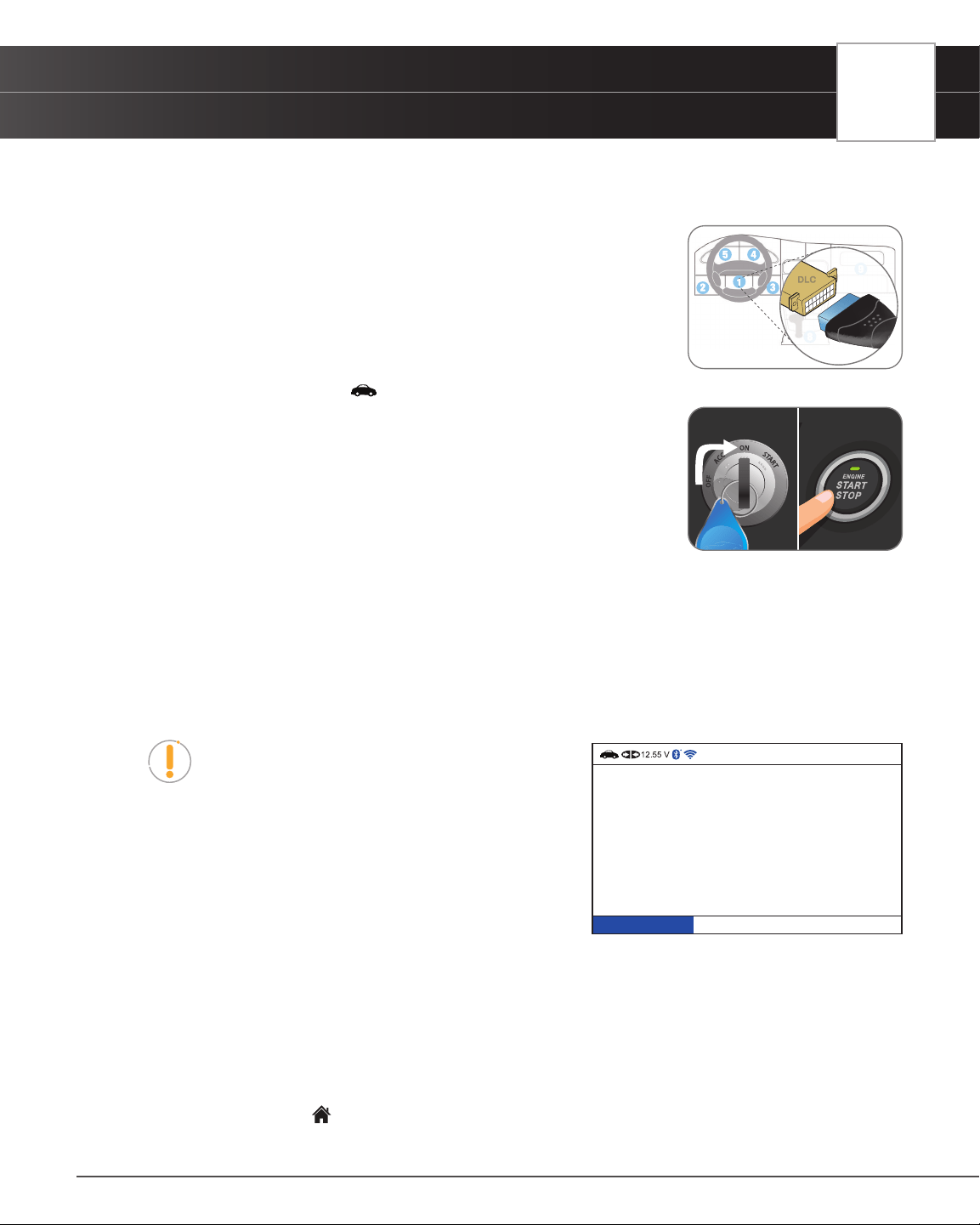
1. Turn the ignition OFF.
2. Locate the vehicle’s 16-pin Data Link Connector (DLC).
3. Connect the Tablet’s cable connector to the vehicle’s DLC. The cable
connector is keyed and will only t one way.
n If you have problems connecting the cable connector to the DLC,
rotate the connector 180° and try again. If you still have problems,
check the DLC on the vehicle and on the Tablet. Refer to your
vehicle’s service manual to check the vehicle’s DLC properly.
n After the Tablet’s test connector is properly connected to the vehicle’s
DLC, the Vehicle icon
should display to conrm a good power connection.
4. Turn the ignition on. DO NOT start the engine.
5. When the Tablet is properly connected to the vehicle’s DLC, the unit
automatically turns ON.
n If the unit does not power on automatically, it may indicate there is no
power present at the vehicle’s DLC connector. Check the fuse panel
and replace any burned-out fuses.
n If replacing the fuse(s) does not correct the problem, consult the vehicle’s repair manual to
identify the proper computer (PCM) fuse/ circuit, and perform any necessary repairs before
proceeding.
6. The Tablet automatically checks the vehicle’s computer to determine which communication protocol it is
using.
n Tablet begins to “AUTO-LINK” to identify computer’s communication protocol. A progress bar
is displayed while a communication link is established.
NOTE: A PROTOCOL is a set of rules and procedures
for regulating data transmission between computers,
and between testing equipment and computers. As of
this writing, ve different types of protocols (ISO 9141,
Keyword 2000, J1850 PWM, J1850 VPW and CAN)
are in use by vehicle manufacturers.
n If the Tablet fails to link to the vehicle’s computer, a
“Communication Error” message shows.
━ Ensure your vehicle is OBD2 compliant.
━ Verify the connection at the DLC, and verify the ignition is ON.
━ Turn the ignition OFF, wait 5 seconds, then back ON to reset the computer.
━ Choose Relink to try again or select OBD2 Menu button to return to the OBD2 Menu.
n If the Tablet cannot link to the vehicle’s computer after three attempts, the message “Contact
Technical Support” displays.
━ Choose the
Home button to return to the Home Screen.
NO Brake Pedal
Tap Button 2 Times
AUTO-LINK in progress.
Linked to CAN.
20%
13
14
USING THE TABLET
OBD2 Diagnostics
━ Turn the ignition OFF and disconnect the Tablet.
━ Contact Technical Support for assistance.
7. If the Tablet can decode the Vehicle Identication Number (VIN) for the vehicle under test, the OBD2 results
screen displays. Proceed to Step 9.
8. If the Tablet cannot decode the Vehicle Identication Number (VIN) for the vehicle under test, the Vehicle
Selection screen displays.
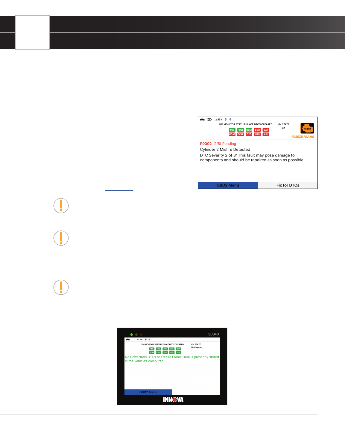
9. After approximately 2~3 seconds, the Tablet will retrieve
and display any Diagnostic Trouble Codes (DTCs), I/M
Monitor Status and Freeze Frame Data retrieved from the
vehicle’s computer memory.
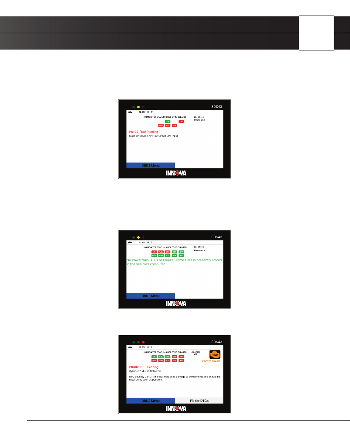
n The Tablet will display a code only if codes are
present. If no codes are present, the message “No
Powertrain DTCs or Freeze Frame Data presently
stored in the vehicle’s computer” displays.
10. Refer to TABLET DISPLAY FUNCTIONS for a description
of display elements. [
See page 6]
NOTE: In the case of long code denitions, a small arrow is shown in the upper/
lower right-hand corner of the display area to indicate the presence of additional
information. Use arrow keys as necessary to scroll through the denition.
NOTE: If a denition for the currently displayed code is not available, an advisory
message shows “The denition for this trouble code is not available. Please connect
your tablet to the update software quarterly to see if a new update is available.”
11. Read and interpret Diagnostic Trouble Codes/system condition using the display and the green, yellow, and
red LEDs.
NOTE: The green, yellow, and red LEDs are used (with the display) as visual aids to
make it easier to determine engine system conditions.
n Green LED – Indicates that all engine systems are running normally, and all emission monitors
are active and performing their diagnostic testing. The Malfunction Indicator “Check Engine”
Lamp on the vehicle’s instrument panel is off.
USING THE TABLET
OBD2 Diagnostics
n Yellow LED – Indicates one of the following conditions:
[A] A PENDING CODE IS PRESENT – If the yellow LED is illuminated, it may indicate a Pending code
is present. Check the display for conrmation. A Pending code is conrmed by the presence of a numeric
code and the word
Pending.
[B] MONITOR NOT RUN STATUS – If the display shows a zero (indicating there are no DTCs present
in the vehicle’s computer memory), but the yellow LED is that some of the Monitors supported by the
vehicle have not yet run and completed their diagnostic testing. Check the display for conrmation. All
Monitor icons that are blinking have not yet run and completed their diagnostic testing; all Monitor icons
that are solid have run and completed their diagnostic testing.
n Red LED – Indicates there is a problem in one or more of the vehicle’s systems. The Malfunction
Indicator “Check Engine” Lamp on the vehicle’s instrument panel is on.
15
16
USING THE TABLET
OBD2 Diagnostics
NOTE: DTC’s that start with “P0”, “P2” and some “P3” are considered Generic
(Universal). All Generic DTC denitions are the same on all OBD2 equipped
vehicles. The Tablet automatically displays the code denitions (if available) for
Generic DTC’s.
NOTE: DTC’s that start with “P1” and some “P3” are Manufacturer specic codes –
their code denitions will vary with each vehicle manufacturer.
FIX FOR DTCs
Innova’s RepairSolutionsPRO reports offer a x, which is cross referenced for accuracy against a database of millions
of veried xes. It is real-world data that has been collected for over 25 years by Innova’s network of ASE Master
Technicians across the U.S. (For the RSPRO App, [
See page 8]
1. From OBD2 Diagnostic screen, select Fix for DTCs, then press OK.
n The tablet veries that it has a registered RSPRO account. If not, the screen displays a screen
requesting that the tablet be registered with an RSPRO account. Follow the steps to create your
account.
n The tablet also veries if its connected to a Wi-Fi Network. [See page 63]
n If the Tablet fails to establish communication, the screen shows a notication. Select Cancel,
then press OK to return to the OBD2 Diagnostic screen or select Try Again, then press OK to
try again.
2. A “One moment please…” message displays while the results are gathered.
n A Disclaimer is provided every time a x is requested.
USING THE TABLET
OBD2 Diagnostics
3. To stop showing this screen, press the OK button to check the “Do not show this again” check-box, select
Conrm and press OK to conrm your selection. Alternatively, select Conrm without the check mark, and press
OK to not make any changes.
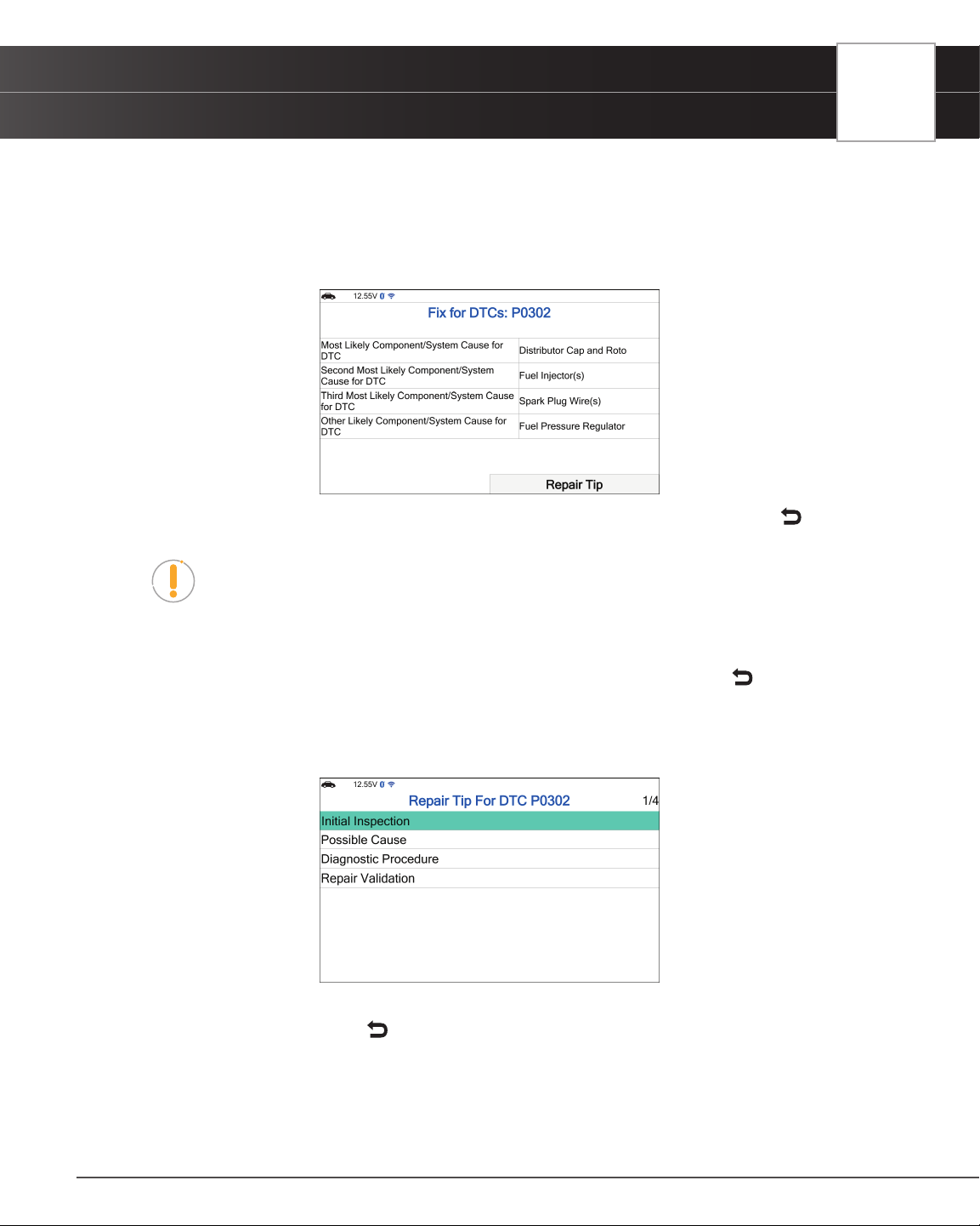
n The results screen displays the recommended Fix for DTCs, and provides the Most Likely
Component/System Cause for the DTC, and any additional most likely x recommendations.
n If a Fix is not available for the retrieved DTC, an advisory message displays. Press the
Back
button to return to the OBD2 Diagnostic screen.
NOTE: A Repair Tip offers additional insight and helpful tips to solve the issue.
4. Select Repair Tip and press OK.
n A Repair Tip menu for the retrieved DTC is provided.
n If a DTC Repair Tip is not available, an advisory message displays. Press the
Back button
to return to the Fix for DTCs screen.
5. Each Repair Tip for DTC includes: Initial Inspection, Possible Cause, Diagnostic Procedure and Repair
Validation.
6. Select the information you wish to view, then press OK.
7. When nished viewing, press the
Back button to return to the Repair Tip menu.
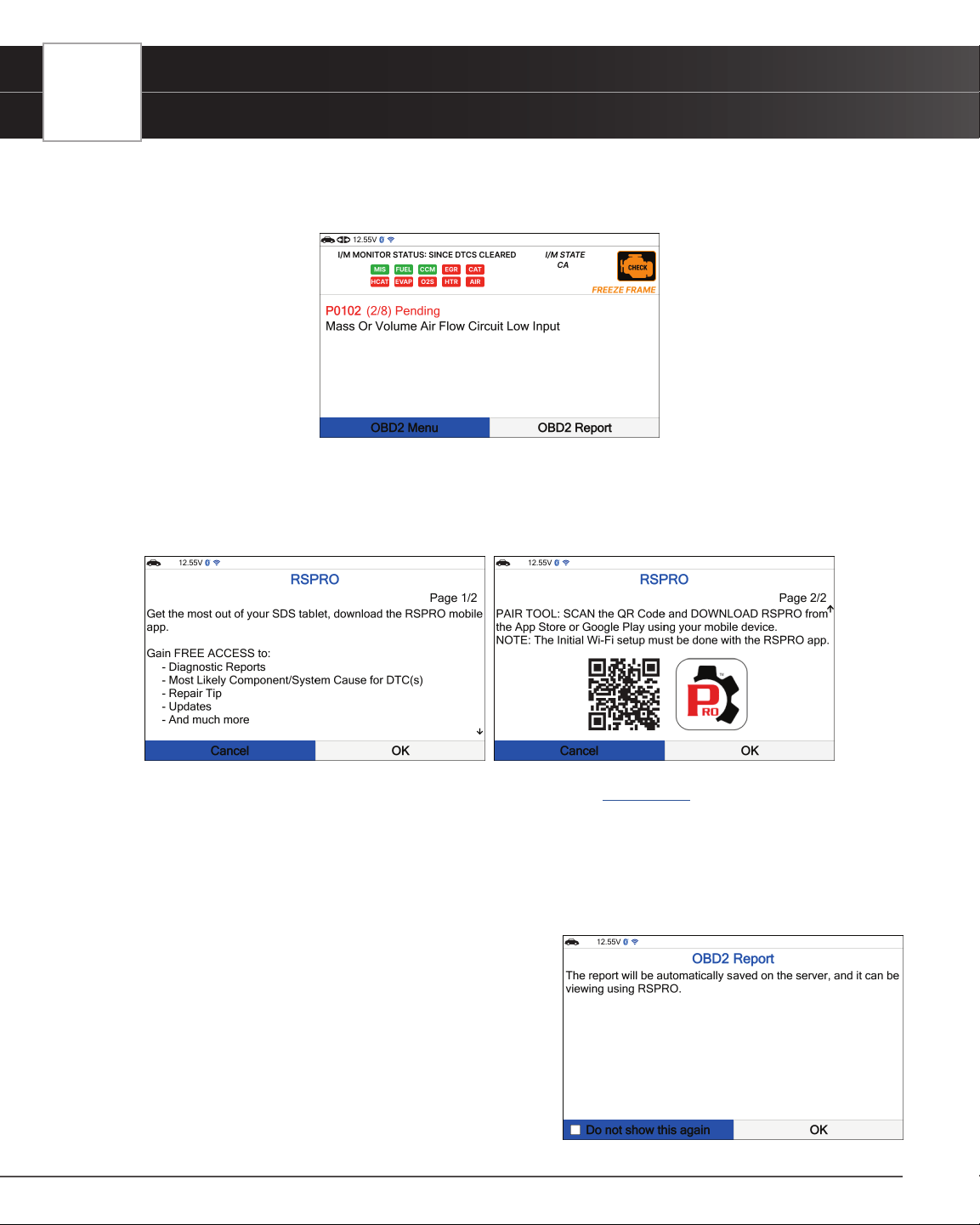
OBD2 REPORT
The OBD2 Report function allows you create an OBD2 Diagnostics Report and upload it to your account, which you
17
18
USING THE TABLET
OBD2 Diagnostics
can view at a later time on your registered RSPRO app. The OBD2 Report function is available from the second DTC
or from the rst DTC that does not offer a Fix for DTC. This option is removed once a report has been successfully
completed and will reappear after each vehicle relink.
1. From OBD2 Diagnostics screen, select the OBD2 Report button then press OK.
n The tablet veries that it has a registered RSPRO account. If not, the screen displays a screen
requesting that the tablet be registered with an RSPRO account. Follow the steps to create your
account.
n The tablet also veries if its connected to a Wi-Fi Network. [See page 63]
n If the Tablet fails to establish communication, a notication is displayed. Select Cancel, then
press OK to return to the OBD2 Diagnostic screen or select Try Again, then press OK to try
again.
2. A “Submitting data…” message displays.
n If the report creation fails, the screen displays a notication and returns to the OBD2 Diagnostics
screen after 3 seconds.
n If the report was successfully created, a
conrmation screen displays.
3. To bypass all these steps, press the OK button to check
the “Do not show this again” check-box, then select and
press OK to conrm your selection. The tool will bypass this
screen the next time it is used, and after each successful
data submission, the screen will return to the OBD2
Diagnostics screen. Alternatively, select OK without the
check mark and press OK to not make any changes.
USING THE TABLET
OBD2 Diagnostics
ERASING DIAGNOSTIC TROUBLE CODES (DTCs) - $04
NOTE: When the Tablet’s ERASE function is used to erase the DTCs from the
vehicle’s on-board computer, “Freeze Frame” data and manufacturer-specic
enhanced data are also erased.
If you plan to take the vehicle to a Service Center for repair, DO NOT erase the codes from the vehicle’s computer. If
the codes are erased, valuable information that might help the technician troubleshoot the problem will also be erased.
Erase DTCs from the computer’s memory as follows:
NOTE: When DTCs are erased from the vehicle’s computer memory, the I/M
Readiness Monitor Status program resets status of all the Monitors to a not run
“ashing” condition. To set all the Monitors to a DONE status, an OBD2 Drive Cycle
must be performed. Refer to your vehicle’s service manual for information on how to
perform an OBD2 Drive Cycle for the vehicle under test.
1. Perform the Code Retrieval procedure [
See page 12]
n Wait until the codes are displayed.
n Press the OK button to access to OBD2 Menu.
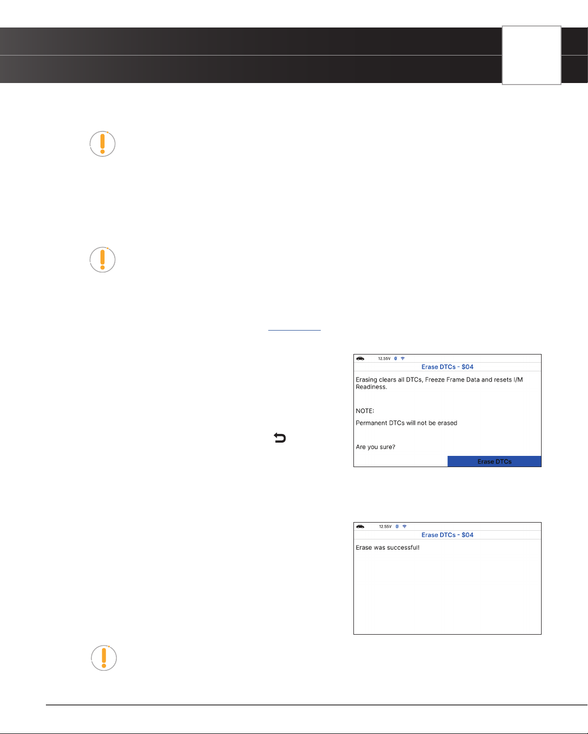
2. From OBD2 Menu, select Erase DTCs - $04, then press
OK button. A conrmation message shows.
n If you are sure you want to proceed, choose Erase
DTCs to continue.
n If you do not want to proceed, press
Back button
to back to OBD2 Menu.
3. Select Erase DTCs then press OK button.
n If the vehicle’s engine is running, an advisory message shows: “Please stop the vehicle and
place transmission in Park or Neutral then press “Erase DTCs” to continue.
n A “One moment please…” message displays while
the erase function is in progress.
4. If the erase was successful, a conrmation message
displays. After 3 seconds, the tablet automatically re-links
to the vehicle’s computer.
n If the erase was not successful, an advisory message
shows indicating the erase request was sent to
the vehicle’s computer. After 3 seconds, the tablet
automatically re-links to the vehicle’s computer.
NOTE: If the erase was not successful and ECU error code $22 is present, an
advisory message display. Start the engine and maintain vehicle speed at 0. Choose
Erase DTCs to try again.
19
20
USING THE TABLET
OBD2 Diagnostics
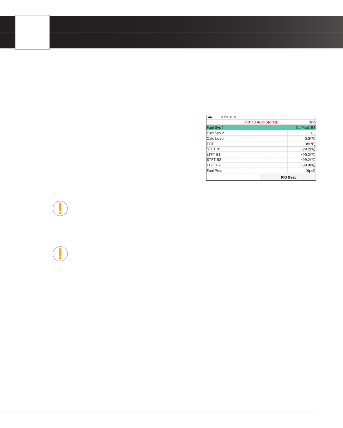
FREEZE FRAME - $02
If more than one Diagnostic Trouble Code (DTC) was retrieved and to view Freeze Frame Data, following procedures
bellow:
1. From OBD2 Menu, select Freeze Frame - $02 and press the OK button.
n The Freeze Frame data displays.
n In OBD2 systems, when an emissions-related engine
malfunction occurs that causes a DTC to set, a record
or snapshot of engine conditions at the time that the
malfunction occurred is also saved in the vehicle’s
computer memory. The record saved is called Freeze
Frame data. Saved engine conditions include, but
are not limited to: engine speed, open or closed
loop operation, fuel system commands, coolant
temperature, calculated load value, fuel pressure,
vehicle speed, air ow rate, and intake manifold
pressure.
NOTE: If more than one malfunction is present that causes more than one DTC to
be set, only the code with the highest priority will contain Freeze Frame data. The
code designated “01” on the Tablet display is referred to as the PRIORITY code and
Freeze Frame data always refers to this code. The priority code is also the one that
has commanded the MIL (Check Engine) lamp on.
NOTE: Retrieved information can be uploaded to a Personal Computer (PC) with
the use of optional software (see instructions included with the software for more
information).
n To view a description of the displayed PID, press PID Desc.
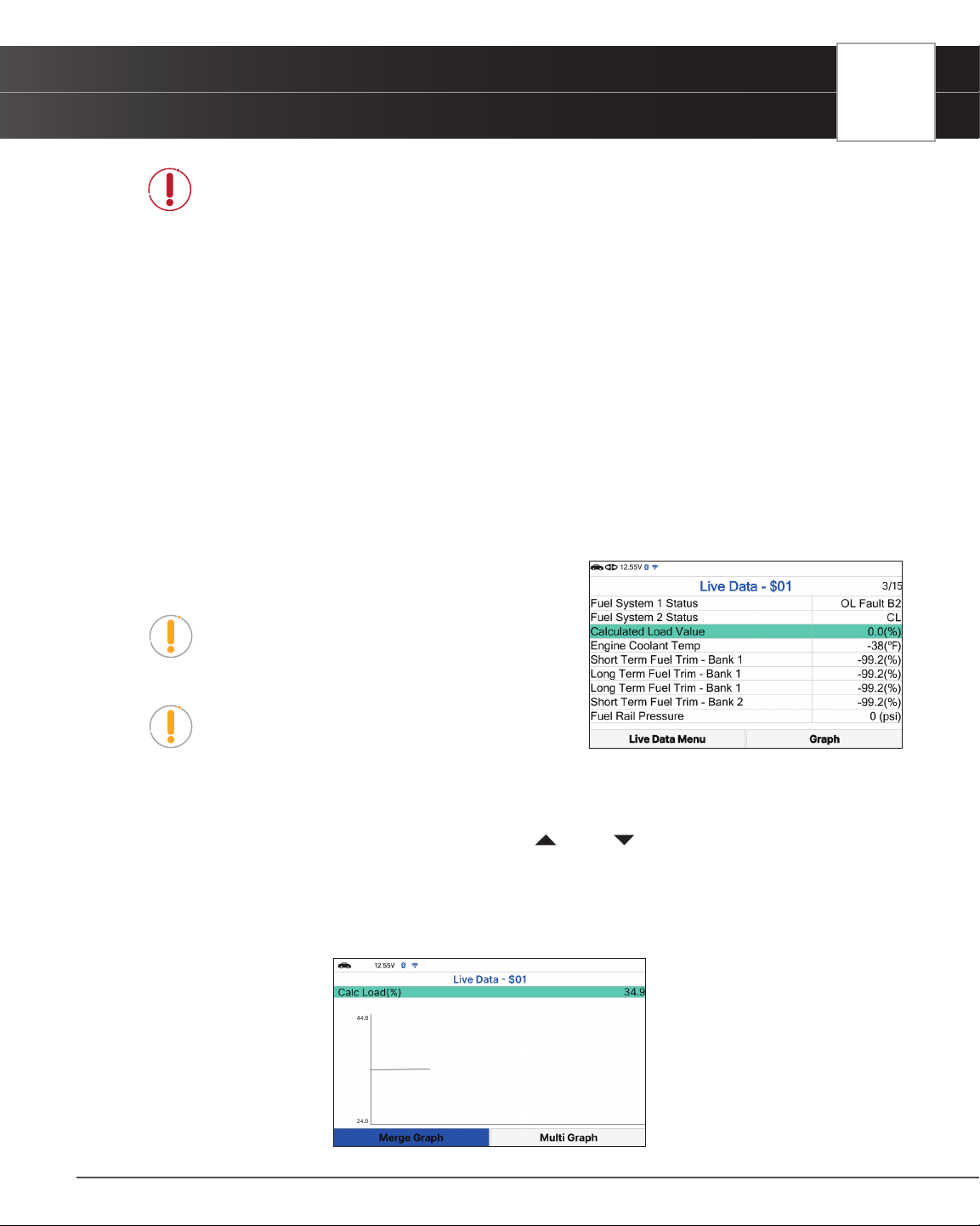
LIVE DATA - $01
The Tablet lets you view “real-time” Live Data. This information includes values (volts, rpm, temperature, speed etc.)
and system status information (open loop, closed loop, fuel system status, etc.) generated by the various vehicle
sensors, switches, and actuators. These are the same signal values generated by the sensors, actuators, switches
and/or vehicle system status information used by the vehicle’s computer when calculating and conducting system
adjustments and corrections.
The real time (Live Data) vehicle operating information (values/status) that the computer supplies to the Tablet for each
sensor, actuator, switch, etc. is called Parameter Identication Data (PID).
Each PID (sensor, actuator switch, status, etc.) has a set of operating characteristics and features (parameters) that
serve to identify it. The Tablet displays this information for each sensor, actuator, switch, or status that is supported by
the vehicle under test.
USING THE TABLET
OBD2 Diagnostics
DANGER: If the vehicle must be driven in order to perform a troubleshooting
procedure, ALWAYS have a second person help you. One person should drive the
vehicle while the other person observes the Tablet data. Trying to drive and operate
the Tablet at the same time is dangerous and could cause a serious trafc accident.
Viewing Live Data
1. From OBD2 Menu, select Live Data - $01, then press OK button.
2. A “One moment please . . .” message displays while the Tablet establishes communication with the vehicle.
n If the Tablet fails to establish communication with the vehicle, a “Communication Error” message
displays.
━ Ensure the vehicle is OBD2 compliant.
━ Verify the connection at the DLC, and verify the ignition is ON.
━ Turn the ignition OFF, wait 5 seconds, then back ON to reset the computer.
━ Press Relink to continue.
3. Real-time Live Data (PID) information supported by the
vehicle under test displays.
NOTE: The values for the various PIDs displayed
may change as the vehicle’s operating conditions
change.
NOTE: The Graph function button will stay inactive if
the selected PID does not report a numerical value.
An example is the Fuel System Status PID, which
reports either Open Loop (OL) or Close Loop (CL).
4. Only a limited amount of PID data can be displayed on the screen at one time. If additional PID data is
available, a small arrow is shown on the display. Press
UP and DOWN, as necessary, to view available
PID data.
n If communication with the vehicle is lost while viewing Live Data, an advisory message is
displayed.
5. Select Graph and press OK to view the currently selected PID in “graph” mode.
21
22
USING THE TABLET
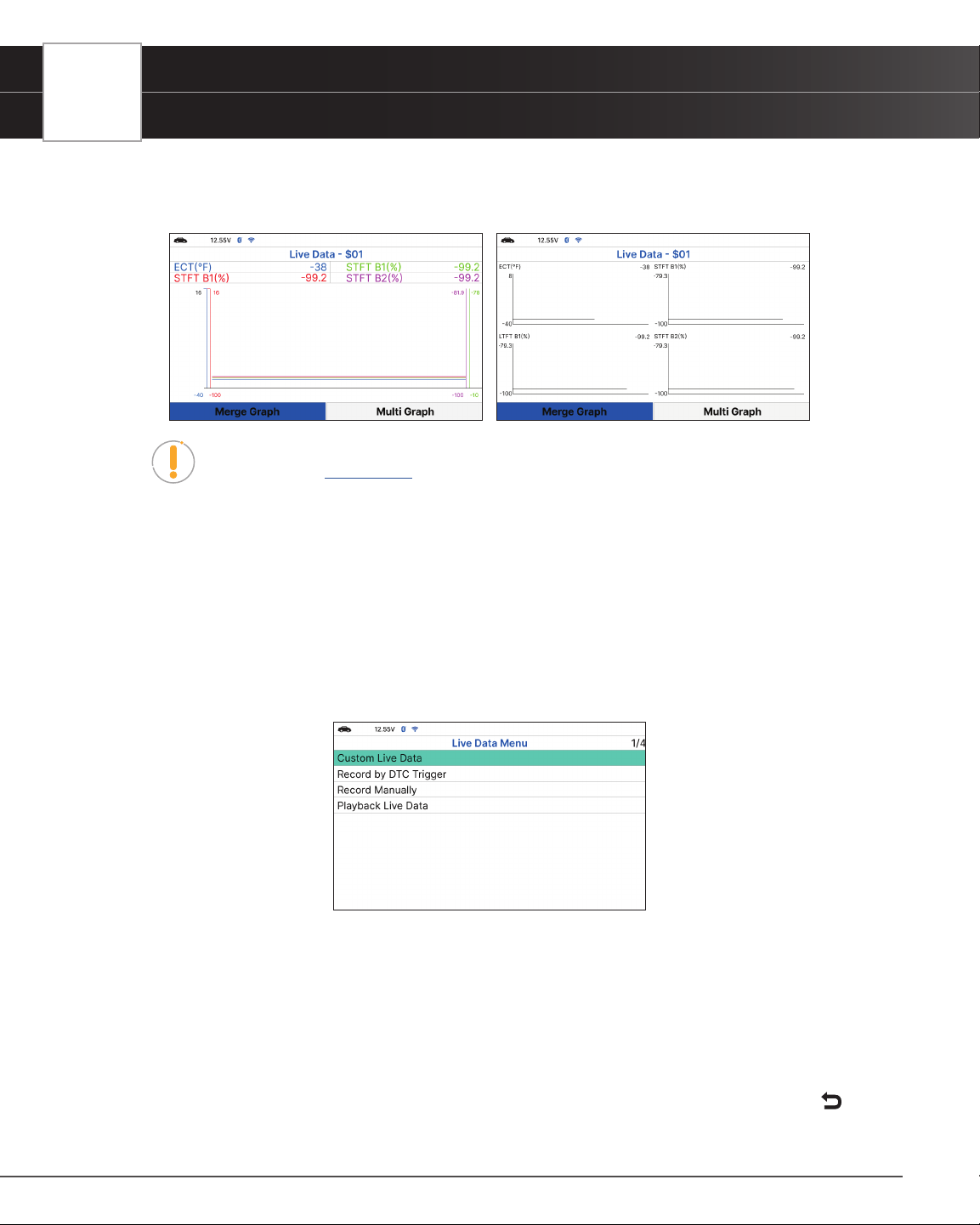
OBD2 Diagnostics
n Choose Merge Graph to view more PID results on one graph.
n Choose Multi Graph to view more Graphs in one screen.
NOTE: The “expanded” denition functionality is available only when enabled
through Settings. [
See page 62]
6. Troubleshoot any diagnostic issues by referencing your vehicle’s repair manual to view and/or compare Live
Data (PID) information displayed on the Tablet against recommended vehicle specications.
Customizing Live Data (PIDs)
You can customize the Live Data display by placing the Tablet in “Custom Live Data” mode and selecting only the
PIDs that you wish to display.
1. With the Tablet in Live Data mode, select Live Data Menu to access the Live Data menu, then select Custom
Live Data and press the OK button.
n If the Tablet fails to establish communication with the vehicle, a “Communication Error” message
displays.
━ Ensure the vehicle is OBD2 compliant.
━ Verify the connection at the DLC, and verify the ignition is ON.
━ Turn the ignition OFF, wait 5 seconds, then back ON to reset the computer.
━ Press Relink to continue.
n If Live Data is not supported by the vehicle under test, an advisory message displays. Press
USING THE TABLET
OBD2 Diagnostics
Back to return to the OBD2 Menu.
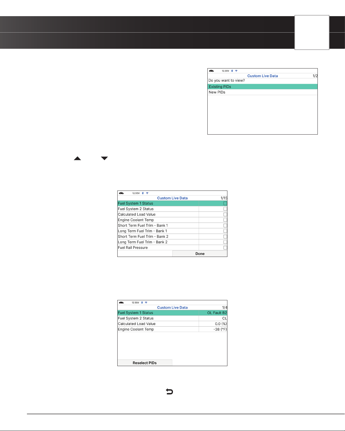
n If custom Live Data was previously congured, the
Select PIDs to Use screen displays.
━ To use the existing custom Live Data selections,
select Existing PIDs, then press OK. Proceed to
step 5.
━ To congure new custom Live Data, select New
PIDs, then press OK. The Custom Live Data menu
displays. Proceed to step 2.
n If custom Live Data was not previously selected, the Custom Live Data menu displays. Proceed
to step 2.
2. Press
UP and DOWN to scroll through the available PIDs. When a PID you wish to display is highlighted,
press OK (a “check-mark” shows to conrm your selection). Repeat until only the PIDs you want to display
are selected.
n To deselect a PID, highlight the PID, then press OK. The check-mark is removed.
3. When you are nished making your selection(s), choose Done to continue.
n If no PIDs have been selected, an advisory message display. Press OK to return to the Custom
Live Data menu.
4. The Tablet is now in “Custom Live Data” mode. Only the PIDs you selected are shown.
n To change the current custom Live Data selections, select Reselect PIDs, then press OK to
return to the Custom Live Data menu. Repeat step 2.
5. To exit the “Custom Live Data” mode, press
Back to return to the Live Data Menu.
23
24
USING THE TABLET
OBD2 Diagnostics
RECORD LIVE DATA
You can record and save several frames of Live Data information for each PID supported by the vehicle in the
Tablet’s memory. Once recorded, each session can be played back for further analysis.
There are two ways that the Tablet can record Live Data:
Record by DTC Trigger
Record Manually
Record by DTC Trigger
This function automatically records Live Data information when a DTC sets and saves it in the Tablet’s memory. The
recorded data can be a valuable troubleshooting aid, particularly if you are experiencing a fault that is causing a
DTC to set. The Tablet can record approximately 100 frames of Live Data.
1. With the Tablet in Live Data mode [
See page 20] select Live Data Menu and press OK to display the Live
Data Menu.
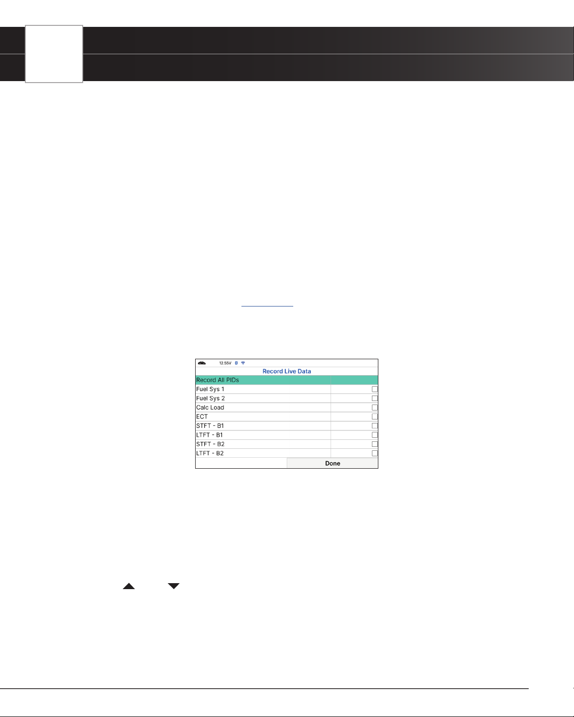
2. Select Record by DTC Trigger, then press OK.
n The Select PIDs to Record screen displays.
n If the Tablet fails to establish communication with the vehicle, a “Communication Error” message
displays.
━ Ensure the vehicle is OBD2 compliant.
━ Verify the connection at the DLC, and verify the ignition is ON.
━ Turn the ignition OFF, wait 5 seconds, then back ON to reset the computer.
━ Press Relink to continue.
3. Press
UP and DOWN to scroll through the available PIDs. When a PID you wish to display is highlighted,
press OK (a “check-mark” shows to conrm your selection). Repeat until only the PIDs you want to record are
selected.
n To select all PIDs, choose Record All PIDs.
n To deselect a PID, highlight the PID, then press OK. The check-mark is removed.
4. When you are nished making your selections, choose Done to continue.
USING THE TABLET
OBD2 Diagnostics
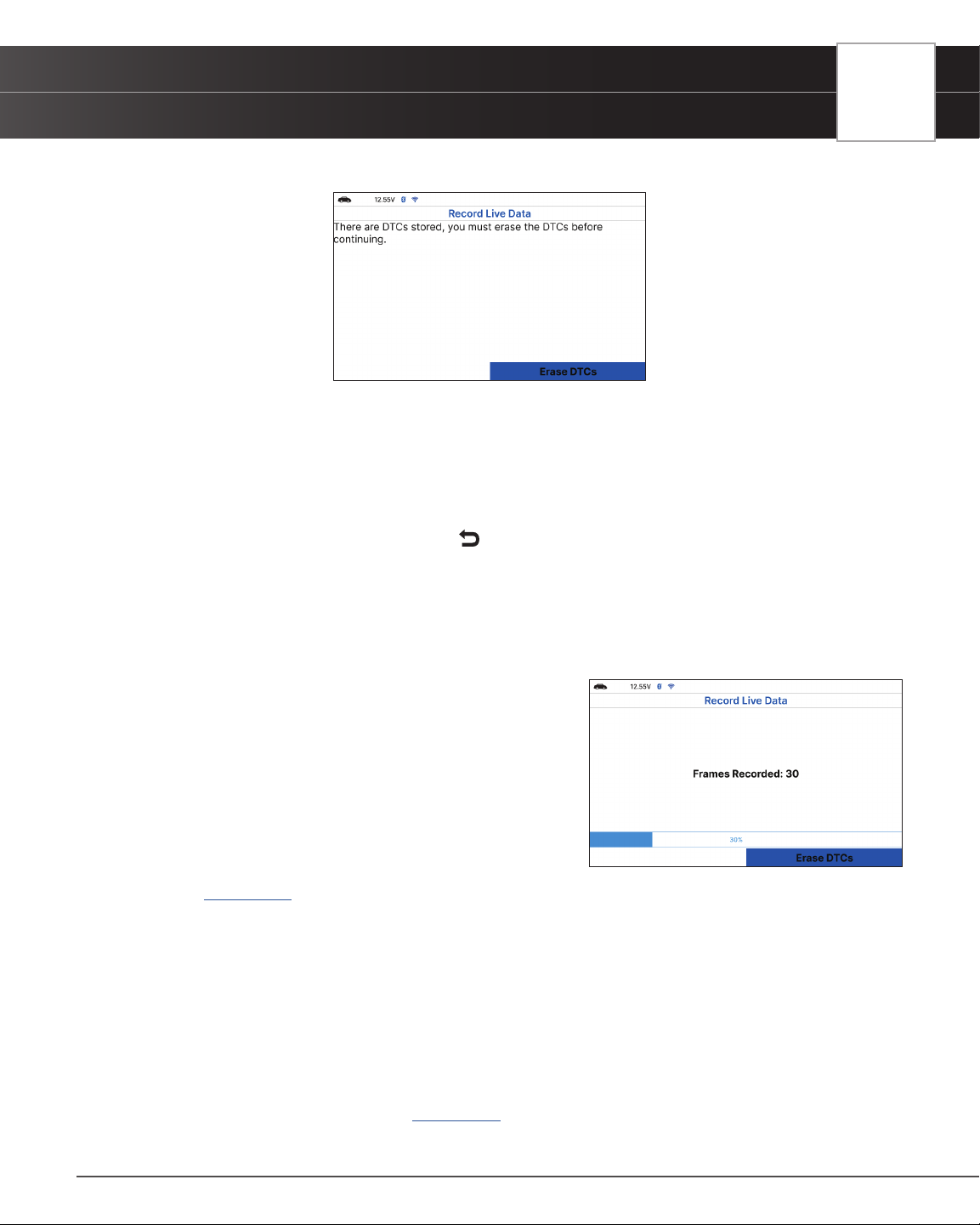
n If DTCs are presently stored in the vehicle’s computer, an advisory message displays.
━ Choose Erase DTCs. A “One moment please…” message displays while DTCs are erased
from the vehicle’s computer.
n If the erase is not successful, an advisory message displays.
━ To retry the erase process, verify that the Tablet is properly connected to the vehicle’s DLC
and that the ignition is on. Choose Erase DTCs.
━ To exit the record function, press
Back to return to the Record Live Data menu.
n When the Erase process is complete, the Record Live Data screen displays the message
“Ready to record. Waiting for DTCs.”
5. Put the engine in the operating condition that causes the DTC to set.
n If necessary, drive the vehicle until you reach the vehicle speed at which the problem occurs.
6. When the Tablet detects a fault that causes a DTC to set,
it automatically records and saves approximately 100
frames of Live Data information in its memory for each PID
selected.
n A progress message shows on the display.
━ You can stop and save recorded Live Data at any
time by choosing Stop/Save.
n When the recording is complete, a conrmation
screen displays. Choose Yes to Playback Live Data
[
See page 26] or No to return to the Live Data menu, as desired.
n If recording was not successful, an advisory message displays. Choose Continue to return
to the Live Data menu.
Record Manually
This option lets you select the precise time at which the Live Data recording will occur. Record by Manually can
be a very valuable tool when troubleshooting intermittent problems that do not meet the requirements for a DTC to
set. The Tablet is capable of recording approximately 100 frames of Live Data.
1. With the Tablet in Live Data mode [
See page 20] select Live Data Menu and press OK to display the Live
Data Menu.
25
26
USING THE TABLET
OBD2 Diagnostics
2. Select Record Manually, then press OK.
n The Select PIDs to Record screen displays.
n If the Tablet fails to establish communication with the vehicle, a “Communication Error” message
displays.
━ Ensure your vehicle is OBD2 compliant.
━ Verify the connection at the DLC, and verify the ignition is ON.
━ Turn the ignition OFF, wait 5 seconds, then back
ON to reset the computer.
━ The Tablet should power up once the ignition is in
the ON position.
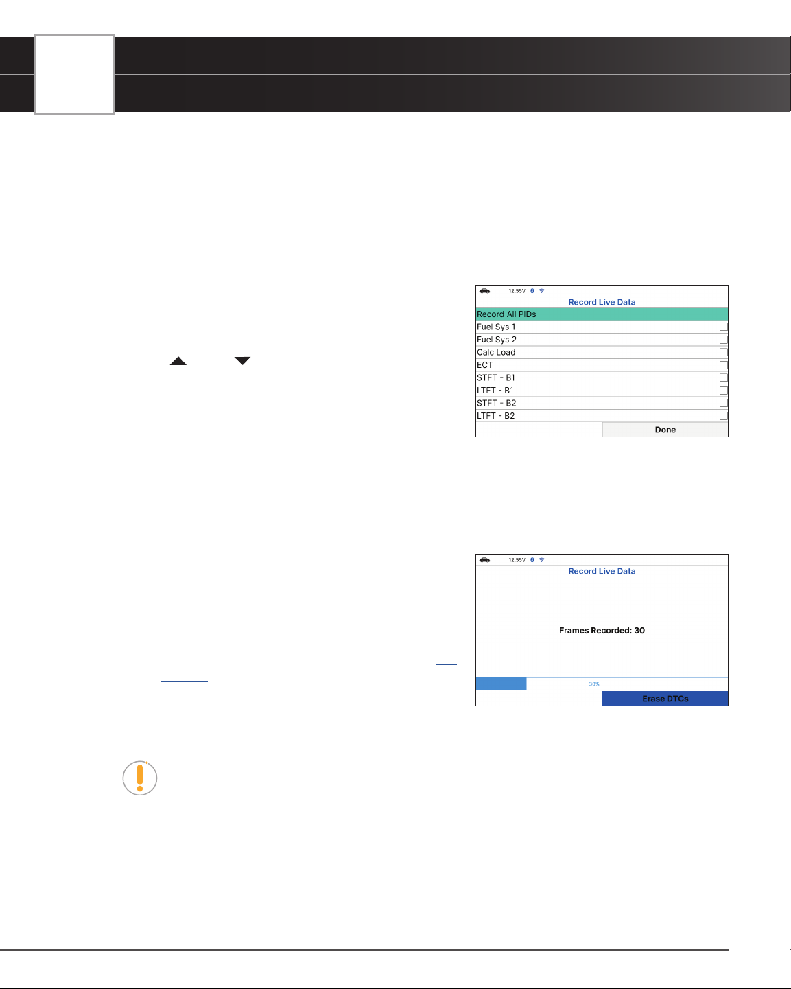
3. Press
UP and DOWN to scroll through the available
PIDs. When a PID you wish to record is highlighted, press
OK (a “check-mark” shows to conrm your selection).
Repeat until only the PIDs you want to record are selected.
n To select all PIDs, choose Record All PIDs.
n To deselect a PID, highlight the PID, then press OK. The check-mark is removed.
4. When you are nished making your selections, choose Done to continue.
n The Record Live Data screen displays.
n Put the engine in the operating condition where the problem manifests itself.
━ If necessary, drive the vehicle until you reach the
vehicle speed at which the problem occurs.
5. When the problem occurs, choose Record.
n A progress message shows on the display.
n When recording is complete, a conrmation screen
displays. Choose Yes to Playback Live Data [
See
page 26
] or No to return to the Live Data menu, as
desired.
n If recording was not successful, an advisory message
display. Choose Continue to return to the Live Data menu.
NOTE: If desired, you can transfer the recorded Live Data information to a personal
computer with the use of optional software (see instructions included with the
software for more information).
PLAYBACK LIVE DATA
Once Live Data has been recorded, it is saved in the Tablet’s memory. You can view recorded Live Data immediately
after recording by selecting Yes from the Record Live Data conrmation screen, or you can view it later using the
“Playback” function.
USING THE TABLET
OBD2 Diagnostics
1. From Live Data Mode, select Live Data Menu and press OK.
2. Select Playback Live Data, then press OK.
n The Playback Live Data menu displays.
NOTE: If there is no Live Data currently stored in the Tablet’s memory, an advisory
message shows on the display. Press View LD to return to Live Data mode.
NOTE: When you select Yes from the Record Live Data conrmation screen, the
Tablet enters the “Live Data Playback” mode, and the
Playback Live Data menu displays.
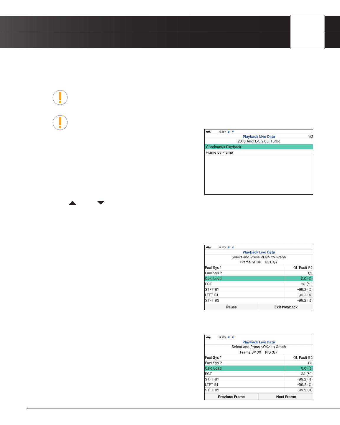
3. Select Continuous Playback or Frame by Frame, as
desired, then press OK.
n The display shows the recorded Live Data, beginning
with the “trigger” frame.
n Only a limited amount of PID data can be displayed on
the screen at one time. If additional PID data is
available, a small arrow is shown on the display. Press
UP and DOWN, as necessary, to view all available PID data.
n When viewing recorded Live Data, look for any irregularities in any of the PID values/signal
information (LTFT %, RPM, MAP, TEMP, etc.). If any PIDs are not within specication, or
irregularities are detected, follow the procedures in the vehicle’s service repair manual to
perform additional troubleshooting and repair.
4. When you select Continuous Playback, the Tablet plays
recorded data at a rate of one frame per 2 seconds.
n Press OK on any selected PID to open a graph view
for that PID.
n Select Pause, to “pause” the Live Data playback.
Select Play to resume the playback mode.
n Select Exit Playback to exit the Live Data Playback
mode and return to the Playback Live Data menu.
n Once playback nishes, the tablet automatically
returns to the Playback Live Data menu.
━ To replay the data again, select Continuous
Playback or Frame by Frame, as desired, then
press OK.
5. When Frame by Frame is selected, you must scroll the
individual frames manually.
n When you have viewed all PID information for the
current frame of Live Data, choose Next Frame or
Previous Frame, as desired.
27
28
USING THE TABLET
OBD2 Diagnostics
n Press OK on any PID to open a graph view for that PID.
n To exit Live Data Playback mode, select Exit Playback selection at the bottom of the list, then
press OK.
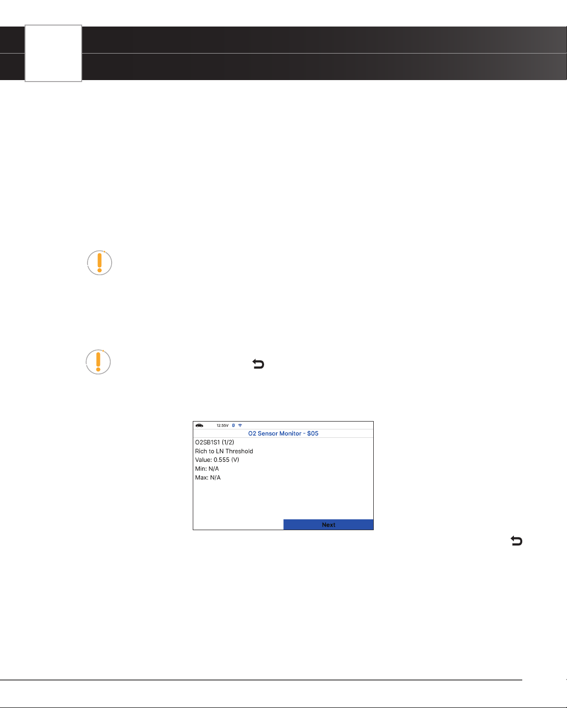
O2 SENSOR MONITOR - $05
The O2 Sensor Monitor lets you view the test results of the vehicle’s two or more O2 sensors. These sensors are
designed to help identify problems that can reduce fuel efciency or increase emissions. Each O2 sensor has a unique
name that identies its location in the exhaust system – cylinder bank location (bank 1 or bank 2) and its location in
relation to the catalytic converter (upstream or downstream). Please reference the vehicle’s service manual for further
information.
NOTE: Service Mode $05 is not supported in ISO 15765-4 (CAN) applications
– it includes the majority of 2008 and older vehicles. For CAN applications, the
functionality of Service Mode $05 was revised and implemented in Service Mode
$06.
1. From OBD2 Menu, select O2 Sensor Monitor - $05, then press OK.
n The O2 Sensor Monitor - $05 screen displays.
NOTE: If the O2 Sensor Monitor is not supported by the vehicle under test, a
notication is displayed. Press the
Back button to return to the OBD2 menu.
2. Choose the item you wish to view, then press OK.
n The screen will show test result.
3. When you have nished viewing the retrieved test data, press Next to view results for the next test, or press
Back to return to Select Test menu.
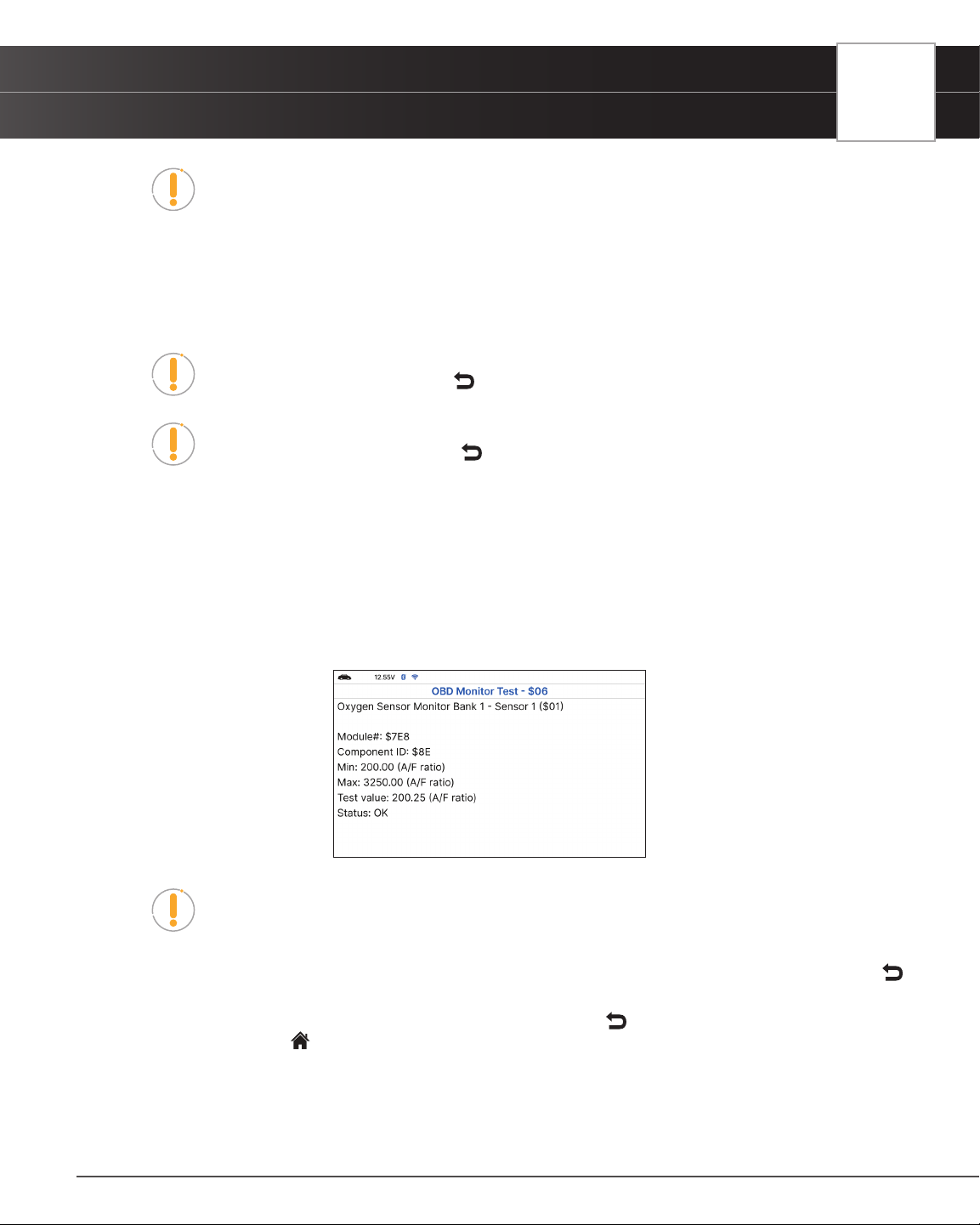
OBD MONITOR TEST - $06
The OBD Monitor Test function retrieves and displays test results for emission-related powertrain components and
systems that are not continuously monitored. The tests available are determined by the vehicle’s manufacturer.
USING THE TABLET
OBD2 Diagnostics
NOTE: The diagnostic tablet does not perform the OBD monitor test but retrieves
results from the most recently performed tests from the on-board computer’s
memory. You may retrieve OBD monitor test results for only one test at any given
time.
1. From the OBD2 Menu, select OBD Monitor Test - $06, then press OK.
2. A “One moment please…” message displays, followed by the Select Test menu screen. (Refer to the vehicle’s
service repair manual for information related to non-continuous tests.)
NOTE: If OBD Monitor Test data is not presently stored in the vehicle’s computer, an
advisory message display. Press the
Back button to return to the OBD2 Menu.
NOTE: If the OBD Monitor Test is not supported by the vehicle under test, an
advisory message displays. Press the
Back button to return to the OBD2 Menu.
3. Select the desired test, then press OK to display the test results. The display shows the following information:
n Test ID number
n Module ID number
n Component ID number
n Min or Max test limit (Only one test limit, either Min or Max, is shown for any given test.)
n Test Value and status.
NOTE: Status is calculated by the diagnostic tablet by comparing the Test Value
against the displayed test limit (either Min or Max). Status is shown as either Low,
High, or OK.
4. When you have nished viewing the retrieved test data, press Next to view results for the next test, or press
Back to return to Select Test menu.
5. When you have nished viewing test data for all desired tests, press
Back from Select Test menu to return to
OBD2 Menu, or press
Home button to return to Home screen.
29
30
USING THE TABLET
OBD2 Diagnostics
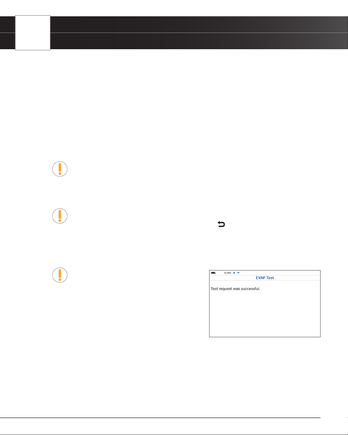
REQUEST CONTROL ON-BOARD SYSTEM - $08
The Request Control On-Board System - $08 allows you perform an EVAP Test or Particulate Filter Regeneration and
Inducement System Reinitialization.
n EVAP Test - lets you initiate a leak test for the vehicle’s EVAP system.
n Particulate Filter Regeneration – this service requests the vehicle to initiate a PF regeneration.
The vehicle manufacturer is responsible to determine the criteria to enable, start and stop the
test, such as engine running, vehicle speed, or engine rpm.
n Inducement System Reinitialization - This service requests the vehicle to initiate a reinitialize
the inducement system. The vehicle manufacturer is responsible to determine the criteria to
enable, start and stop the test, such as engine running, vehicle speed, or engine rpm.
NOTE: The tablet does not perform the leak test, but signals to vehicle’s on-board
computer to initiate the test. The vehicle manufacturer determines the criteria and
method for stopping the test once it has been started. BEFORE using the Request
Control On-Board System function, refer to the vehicle’s service manual to determine
the procedures necessary to stop the test.
NOTE: Some vehicle manufacturers do not allow Tablets or other external devices to
control vehicle systems. If the Request Control On-Board System is not supported by
the vehicle under test, an advisory message displays. Press
Back to return to the
OBD2 Menu.
1. From the OBD2 Menu, select Request Control On-Board System - $08.
n A Request Control On-Board System - $08 screen displays.
NOTE: The EVAP Test use for Spark Ignition, and
the Particulate Filter Regeneration and Inducement
System Reinitialization use for Compression Ignition.
2. Select the test displays on screen, then press OK.
n A “One moment please…” message displays while
the tablet performs the test.
3. When the test has been initiated by the vehicle’s on-board
computer, a conrmation message displays.
DRIVE CYCLE PROCEDURES
A Drive Cycle for a Monitor requires that the vehicle is driven in such a way that all the required “Enabling Criteria”
for the Monitor to run and complete its diagnostic testing are met. You can use the Tablet to view the Drive Cycle
Procedures for a selected Monitor.
1. From OBD2 Menu, select Drive Cycle Procedures, then press OK.
n A “One moment please…” message displays while the Tablet retrieves Monitor status.
USING THE TABLET
OBD2 Diagnostics
NOTE: If the Tablet retrieves Permanent DTCs only, MIL Off and California state is
selected, Drive Cycle Procedures can be viewed from the OBD2 Diagnostic screen.
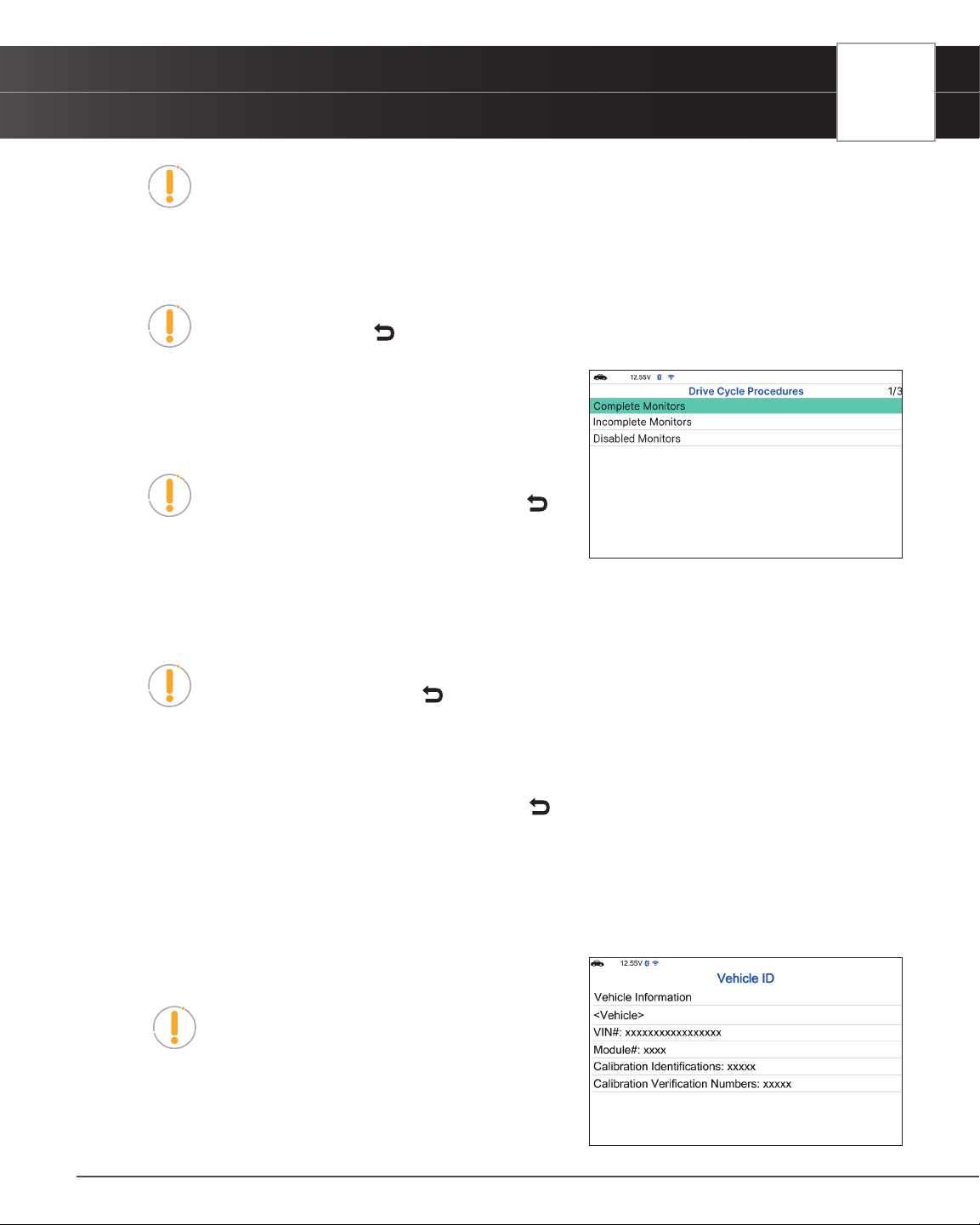
2. When Monitor status has been retrieved, the Drive Cycle Procedures menu displays. Depending on the Monitor
status, you can view Drive Cycle Procedures for Complete Monitors, Incomplete Monitors or Disabled
Monitors.
NOTE: If Drive Cycle Procedures are not available for the vehicle, an advisory
message displays. Press
Back to return to the OBD2 Menu.
3. Select Complete Monitors, Incomplete Monitors or Disabled
Monitors, as desired, then press OK.
n A list of the available Monitors for the selected status
displays.
NOTE: If no Monitors for the selected status are
detected, an advisory message displays. Press
Back to return to the OBD2 Menu.
4. Select the Monitor for which you wish to view Drive Cycle
Procedures, then press OK.
n A “One moment please…” message displays while the Tablet retrieves the requested Drive
Cycle Procedure. Once retrieved, the Drive Cycle Procedures screen displays.
NOTE: If a Drive Cycle Procedure for the selected Monitor is not available, an
advisory message shows. Press
Back to return to the OBD2 Menu.
5. The Drive Cycle Procedure screen shows the specic set of operating procedures that ensure the vehicle is
driven in such a way that all the required “Enabling Criteria” for the Monitor to properly run and complete its
diagnostic testing.
6. When nished viewing the Drive Cycle Procedures, press
Back to return to the Drive Cycle Procedures menu.
VIEWING VEHICLE INFORMATION - $09
The Tablet offers three options for retrieving reference information for the vehicle under test: Vehicle ID, Available
Modules and In-use Performance Tracking.
Viewing Vehicle ID
NOTE: The Vehicle ID function is applicable to model
year 2000 and newer OBD2-compliant vehicles.
The Tablet can retrieve a list of information (provided by the
vehicle’s manufacturer), unique to the vehicle under test, from
its on-board computer. This information may include:
31
32
USING THE TABLET
OBD2 Diagnostics
n The vehicle’s VIN number.
n The control module identication number.
n The vehicle’s calibration ID(s). These IDs uniquely identify the software version(s) for the
vehicle’s control module(s).
n The Vehicle’s Calibration Verication Number(s) (CVNs) required by ODB2 regulations. CVNs
are used to determine if emission-related calibrations for the vehicle under test have been
changed. One or more CVNs may be provided by the vehicle’s computer.
1. From OBD2 Menu, select Vehicle Information, then press OK.
n The Vehicle Information menu displays.
2. Select Vehicle ID, then press OK.
NOTE: The rst time the Vehicle ID function is used, it may take several minutes to
retrieve the information from the vehicle’s computer.
3. When the retrieval process is completed, the vehicle ID information displays.
4. When nished viewing the retrieved vehicle ID information, press
Back to Vehicle Information menu.
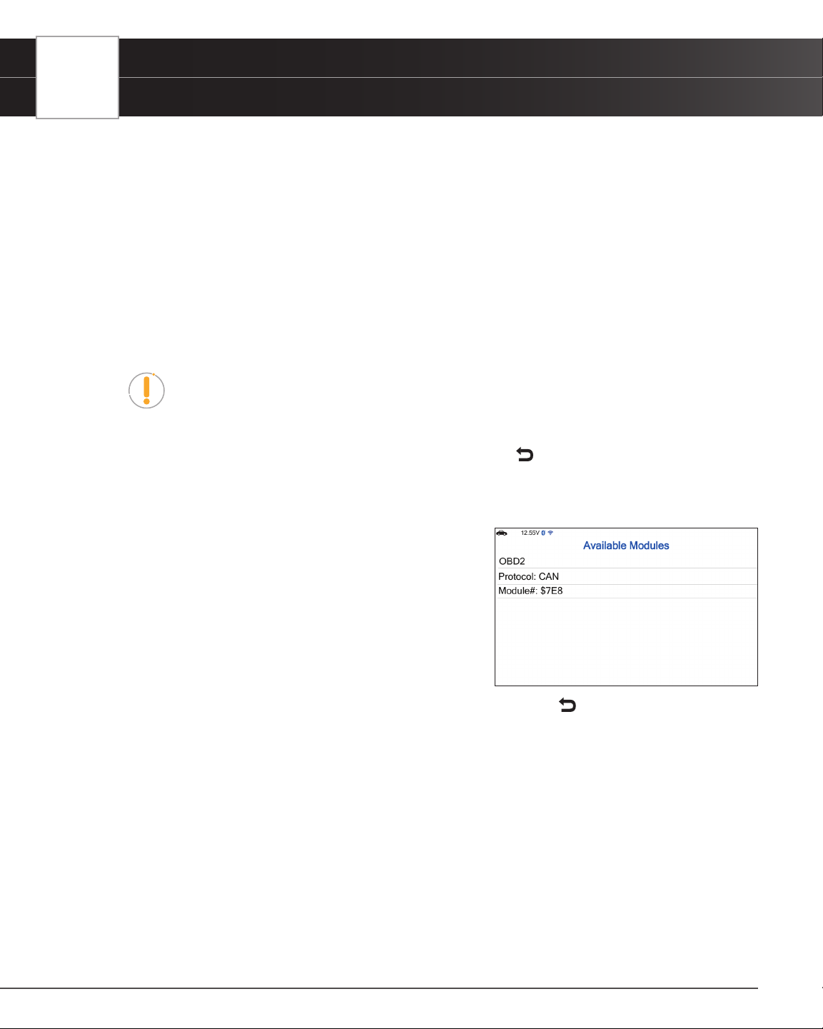
Viewing Available Modules
The Tablet can retrieve a list of modules supported by the vehicle
under test.
1. From OBD2 Menu, select Vehicle Information, then press
OK.
n The Vehicle Information menu displays.
2. Select Available Modules, then press OK.
3. When the retrieval process is completed, a complete list
of modules supported by the vehicle under test displays.
4. When you have nished viewing the list of available modules, press
Back to return to the Vehicle
Information menu.
Viewing In-Use Performance Tracking
The Tablet can retrieve In-use Performance Tracking (IPT) statistics for monitors supported by the vehicle under
test. Two values are returned for each monitor; the number of times that all conditions necessary for a specic
monitor to detect a malfunction have been encountered (XXXCOND), and the number of times that the vehicle
has been operated under the specic conditions for the monitor (XXXCOMP). Statistics are also provided for the
number of times the vehicle has been operated in OBD monitoring conditions (OBDCOND), and the number of
times the vehicle’s engine has been started (IGNCNTR).
1. From OBD2 Menu, select Vehicle Information, then press OK.
n The Vehicle Information menu displays.
USING THE TABLET
OEM Diagnostics
2. Select In-Use Performance Tracking then press OK.
3. When the retrieval process is completed, the In-use Performance Tracking statistics for the vehicle under
test display.
n If In-use Performance Tracking is not available for your vehicle, an advisory message shows on
the diagnostic tablet’s display. Press
Back to return to the Vehicle Information Menu.
4. When you have nished viewing the list of available modules, press Back to return to the Vehicle
Information menu.
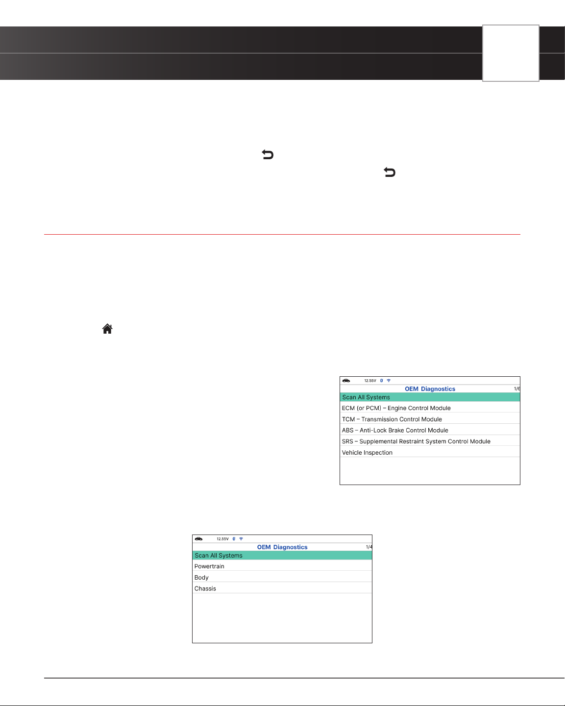
OEM DIAGNOSTICS
The OEM Diagnostics function allows you to perform enhanced, OEM level diagnostics not available over generic
OBD2. A network scan allows you to scan all or just one vehicle module to retrieve DTCs associated with the module(s).
Get access to hundreds of additional parameters that you can view in real-time for ABS, Airbag (SRS), Transmission,
and Engine Control Module. Plus, perform bidirectional tests on fuel pump, injectors, ignition coils, and much more.
You can even provide a comprehensive Vehicle Inspection report that shows the complete Diagnostic Report, Customer
Report, and the Collision Industry Report – offering a complete overview of the vehicle’s current health status.
1. From
Home Screen, select OEM Diagnostics and press OK.
2. A selection dialog is provided.
3. Select the type of test you wish to perform.
n Select Scan All Systems to perform a comprehensive
vehicle scan of all available network modules.
n Select Vehicle Inspection to perform a complete
vehicle health status report, including: OBD2 check,
all Network system scan, service checks, warning
lights, tire pressures, and more.
n Select the “individual” listed control module name to
perform a diagnostic check on that single module.
PERFORM A SCAN - SCAN ALL SYSTEMS
1. Select Scan All Systems from the OEM Diagnostics screen, then press OK.
n The Module Selection displays.
33
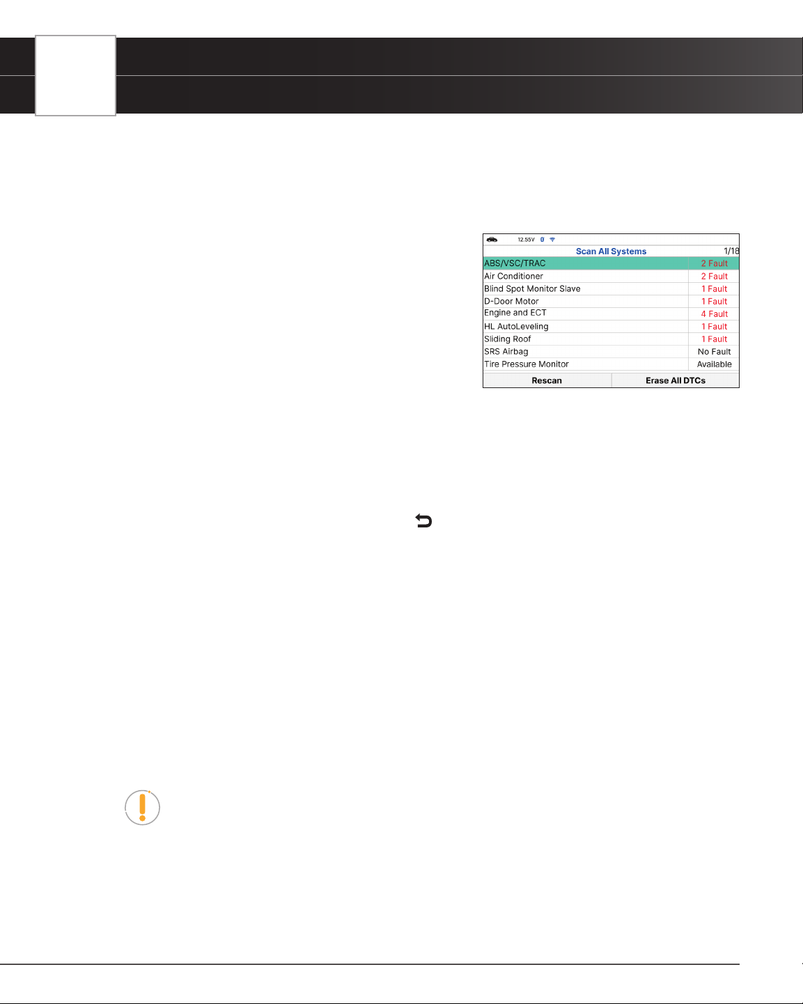
34
USING THE TABLET
OEM Diagnostics
2. Choose Scan All Systems, then press OK.
n A “Linking…” message displays while the Tablet scans all available modules.
n When the scan is complete, the All Modules Scan screen displays. The screen shows the
number of DTCs recorded for each available module.
n The results window lists all tested Control Modules
with its corresponding result:
━ Fault – Indicates the number of reported DTCs.
━ No Fault – Indicates that no DTCs were found.
━ Available – Indicates that the module is part of
the system but does not report DTCs.
n The results screen also allows too either:
━ Erase All DTCs - Erases all the vehicle’s retrieved
Diagnostic Trouble Codes (DTC).
━ Rescan - Performs to scan all systems again.
n Select the desired system, then press OK.
3. Depending on the module selected, you can Read DTCs, Erase DTCs, view Live Data, perform Active Test or
read ECU Information.
4. Choose the function you would like to run. Or press
Back to return to the selected module screen.
n Read DTCs
n Erase DTCs
n Live Data
n Active Test
n ECU Information
Reading DTCs for a Selected Module
1. Select the module for which you wish to read DTCs.
n Select Read DTCs in the selected module screen.
2. The tablet retrieves and displays DTCs stored in the vehicle’s computer for the currently selected module.
NOTE: If no DTCs for the selected module are currently stored in the vehicle’s
computer, the message “No ‘modules’ DTCs are presently stored in the vehicle’s
computer” displays.
3. Select Erase DTCs to erase ALL retrieved Diagnostic Trouble Codes (DTCs).
Erasing DTCs for a Selected Module
1. Select the module for which you wish to erase its DTCs.

USING THE TABLET
OEM Diagnostics
2. Choose Erase DTCs. A conrmation message shows.
n Ensure that the ignition in the Key ON, Engine OFF position.
n If you are sure you want to proceed, choose Erase DTCs for a second time.
n If you do not want to proceed, press
Back to cancel the erase procedure.
3. If you selected to erase its DTCs, a “One moment please…” message displays while the erase function is in
progress.
n If the erase was successful, a conrmation message displays. After 3 seconds, the Tablet will
automatically re-scan the currently selected module.
n If the erase was not successful, an advisory message displays indicating the erase request
was sent to the vehicle’s computer. After 3 seconds, the Tablet will automatically re-scan the
currently selected module.
Viewing Live Data for a Selected Module
Follow these steps to view Live Data for the currently selected module.
1. Select the module for which you wish to view its Live Data, then press OK.
n The individual module menu screen displays.
2. Select Live data, then press OK.
n The results screen displays all the vehicle’s available PIDs with reported values.
n Refer to OBD2 Live Data [See page 20] on how to use Live Data mode.
PERFORM ACTIVE TEST FOR A SELECTED MODULE
Active Test lets you perform active tests for various vehicle actuators and systems. It offers the most popular
function tests available for 7 vehicle brands – Chrysler, GM, Ford, Hyundai, Nissan, Toyota, and Honda.
1. Select the module you wish to perform the Active Test on, then press the OK button.
n The individual module menu screen displays.
2. Select Active Test, then press the OK button.
n The tablet retrieves and displays a menu of Active Tests available for the vehicle under test.
NOTE: If Active Test are not supported for this vehicle under test, the message
“Active Test is not supported” displays. Select Exit to return to the previous page.
Chrysler Active Tests
Depending on the vehicle under test, the Active Test menu provides access to one or more of the following tests
on Chrysler vehicles:
n NVLD Evaporative Vent Valve Solenoid Control State
35
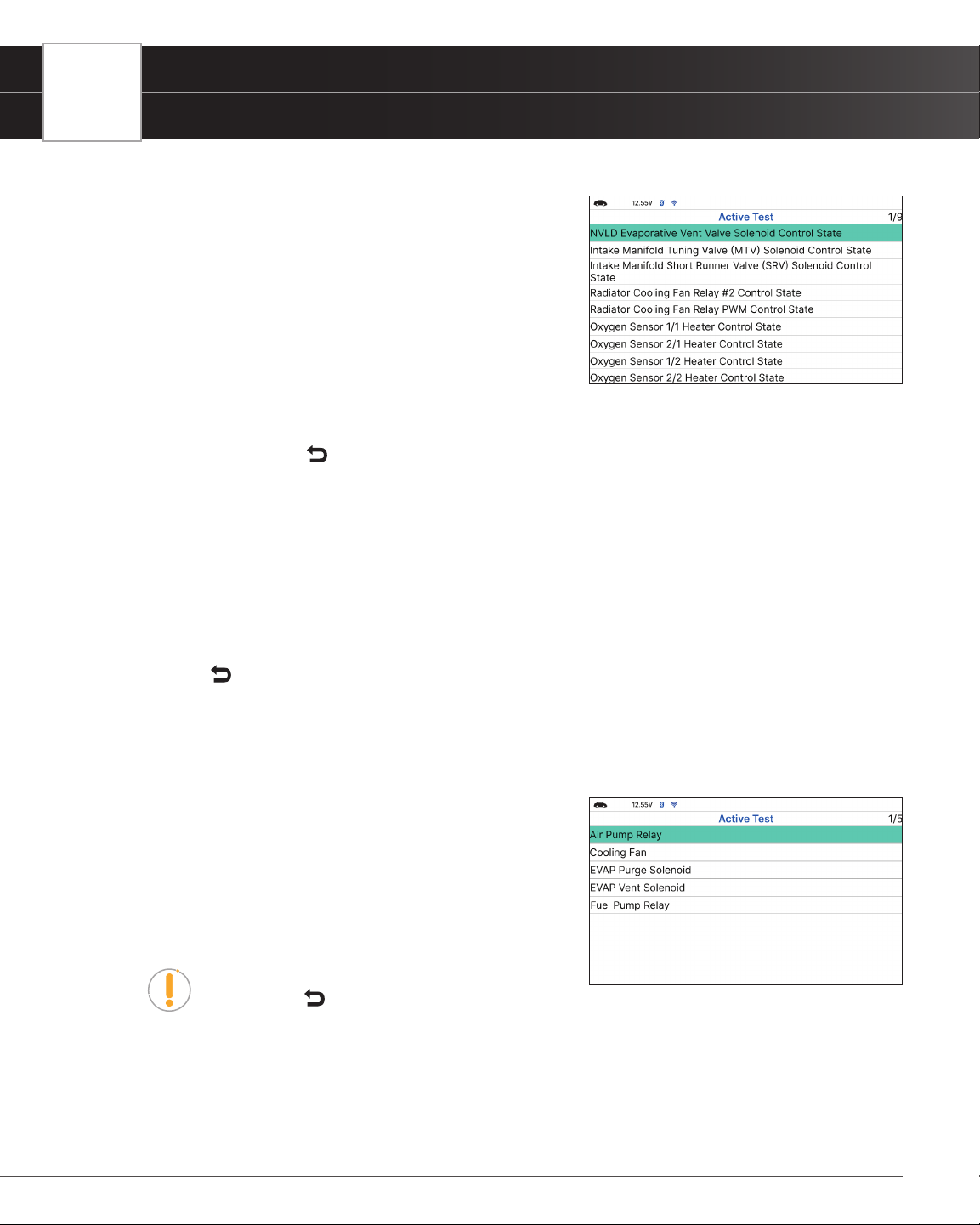
36
USING THE TABLET
OEM Diagnostics
n Intake Manifold Tuning Valve (MTV) Solenoid Control State
n Intake Manifold Short Runner Valve (SRV) Solenoid
Control State
n Radiator Cooling Fan Relay #2 Control State
n Radiator Cooling Fan Relay PWM Control State
n Oxygen Sensor 1/1 Heater Control State Oxygen
Sensor 2/1 Heater Control State
n Oxygen Sensor 1/2 Heater Control State
n Oxygen Sensor 2/2 Heater Control State
NOTE: If an error occurs while performing any function, an “advisory” message
displays. Press
Back to return to the Active Test menu.
NVLD Evaporative Vent Valve Solenoid Control State
1. Select NVLD Evaporative Vent Valve Solenoid Control State in the PCM Active Test menu, then press OK.
n The screen shows Live data.
2. Select On, Off, or Toggle as desired, then press OK.
n The screen refreshes to show the Result.
3. Press
Back to return to the PCM Active Test menu.
GM Active Tests
Depending on the vehicle under test, the Active Test menu provides access to one or more of the following tests on
GM vehicles:
Air Pump Relay
Cooling Fan
EVAP Purge Solenoid
EVAP Vent Solenoid
Fuel Pump Relay
NOTE: If an error occurs while performing any
function. Press
Back to return to the Active Test menu.
Air Pump Relay Test
The Air Pump Relay function lets you turn the Air Pump Relay ON or OFF.

USING THE TABLET
OEM Diagnostics
1. Select Air Pump Relay in the ECM Active Test menu, then press OK.
n An “instructional” screen displays. Follow the instructions to prepare the vehicle for the test
procedure.
2. Press On or Off as desired.
n The screen refreshes to show the Result.
3. Press
Back to return to the Active Test menu.
Cooling Fan Test
The Cooling Fan function lets you control the fan speed.
1. Select Cooling Fan in the ECM Active Test menu, then press OK.
n Wait for a few seconds to link the Control Unit.
n The Cooling Fan screen displays.
n The screen shows the “Commanded State”, “Fan Relay 1”, “Fan Relays 2 and 3”,”Fan Relays
1, 2 and 3” and Off.
2. Select the fan speed you wish.
n The Commanded State shows the result.
3. Press
Back to return to the ECM Active Test menu.
EVAP Purge Solenoid Test
The EVAP Purge Solenoid function lets you Increase or Decrease EVAP purge solenoid.
1. Select EVAP Purge Solenoid in the ECM Active Test menu, then press OK.
n Wait for a few seconds to link the Control Unit.
n The EVAP Purge Solenoid screen displays.
2. Select Increase or Decrease as desired, then press OK.
n The screen refreshes to show the test result.
3. Press
Back to return to the ECM Active Test menu.
EVAP Vent Solenoid Test
The EVAP Vent Solenoid function lets you turn EVAP vent solenoid ON or OFF.
1. Select EVAP Vent Solenoid in the ECM Active Test menu, then press OK.
n The EVAP Vent Solenoid screen displays.
2. Select On or Off as desired, then press OK.
n The screen refreshes to show the test result.
37
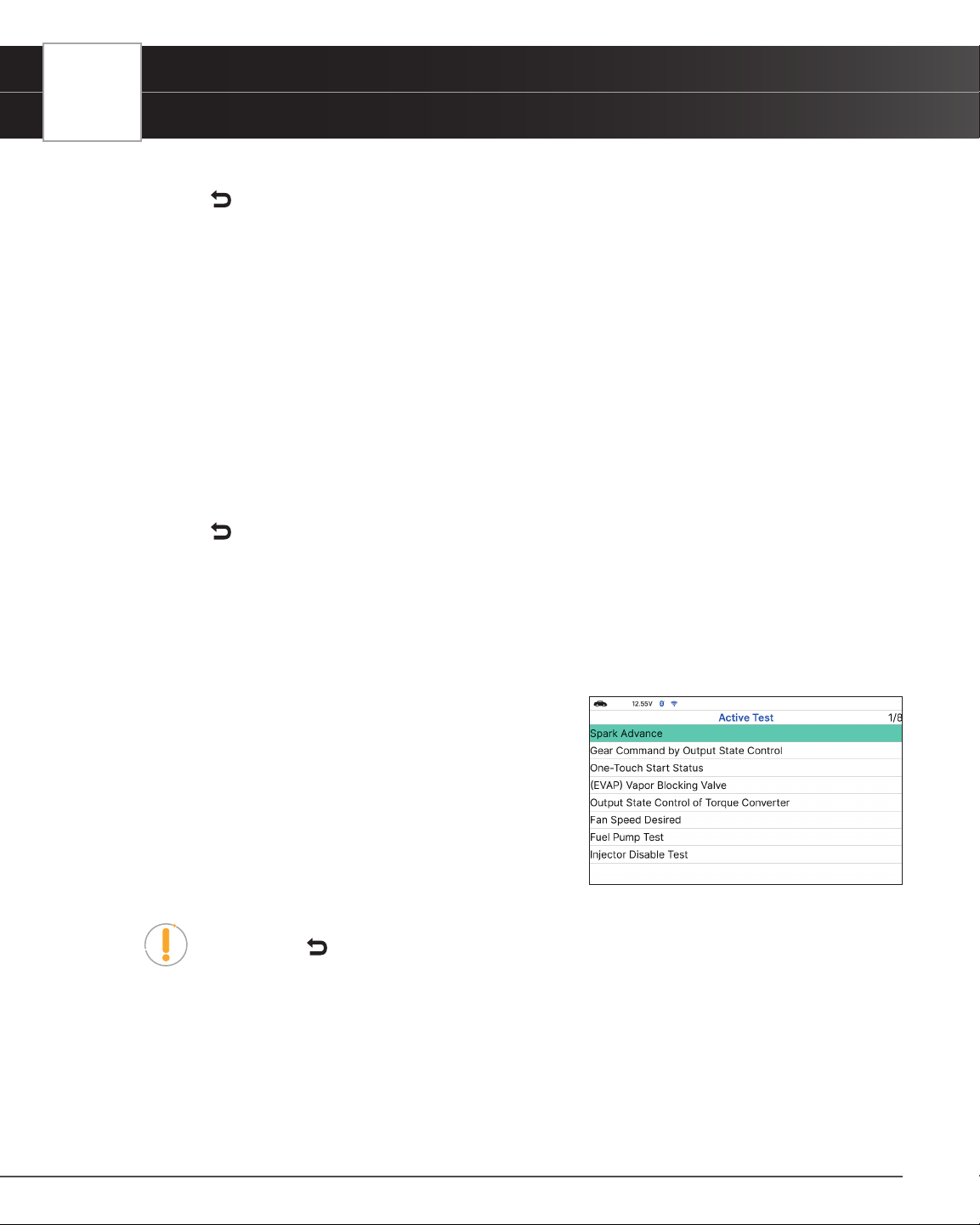
38
USING THE TABLET
OEM Diagnostics
3. Repeat step 2 as desired.
4. Press
Back to return to the ECM Active Test menu.
Fuel Pump Relay Test
The Fuel Pump Relay function lets you turn the fuel pump relay ON or OFF.
1. Select Fuel Pump Relay in the Active Test menu, then press OK.
n An “informational’ screen displays.
2. Choose Next to continue.
n The Fuel Pump Relay screen displays.
3. Select On or Off, as desired, then press OK.
n The screen refreshes to show the test result.
4. Repeat step 3 as desired.
5. Press
Back to return to the Active Test menu.
Ford Active Tests
Depending on the vehicle under test, the Active Test menu provides access to one or more of the following tests on
Ford vehicles:
Spark Advance
Gear Command by Output State Control
One-Touch Start Status
(EVAP) Vapor Blocking Valve
Output State Control of Torque Converter
Fan Speed Desired
Fuel Pump Test
Injector Disable Test
NOTE: If an error occurs while performing any function, an “advisory” message
displays. Press
Back to return to the Active Test menu.
Spark Advance Test
The Spark Advance function lets you increase or decrease spark advance.
1. Select Spark Advance in the Active Test menu, then press OK.
n An “instructional” screen displays. Prepare the vehicle for test as directed:

USING THE TABLET
OEM Diagnostics
━ Place the transmission in PARK.
━ Start and idle the engine.
2. Press OK to continue.
n The Spark Advance screen displays.
3. Select Increase or Decrease, as desired, then press OK.
n The screen refreshes to show the test result.
4. Repeat step 3 as desired.
5. Press
Back to return to the Active Test menu.
Gear Commanded by Output State Control Test
The Gear Commanded by Output State Control function lets you select the transmission gear command.
1. Select Gear Commanded by Output State Control in the Active Test menu, then press OK.
n An “instructional” screen displays. Prepare the vehicle for test as directed:
n Turn the ignition on. DO NOT start the engine.
2. Press OK to continue.
n The Gear Commanded by Output State Control screen displays.
3. Select the gear to be commanded, as desired, then press OK.
n The screen refreshes to show the test result.
4. Repeat step 3 as desired.
5. Press
Back to return to the Active Test menu.
One-Touch Start Status Test
The One-Touch Start Status function lets you enable or disable one touch start functionality.
1. Select One-Touch Start Status in the Active Test menu, then press OK.
n An “instructional” screen displays. Prepare the vehicle for test as directed:
━ Turn the ignition on. DO NOT start the engine.
2. Press OK to continue.
n The One-Touch Start Status screen displays.
3. Select Disabled or Enabled, as desired, then press OK.
n The screen refreshes to show the test result.
4. Repeat step 3 as desired.
5. Press
Back to return to the Active Test menu.
39

40
USING THE TABLET
OEM Diagnostics
(EVAP) Vapor Blocking Valve Test
The (EVAP) Vapor Blocking Valve function lets you turn the vapor blocking valve ON or OFF.
1. Select (EVAP) Vapor Blocking Valve in the Active Test menu, then press OK.
n An “instructional” screen displays. Prepare the vehicle for test as directed:
━ Turn the ignition on. DO NOT start the engine.
2. Press OK to continue.
n The (EVAP) Vapor Blocking Valve screen displays.
3. Select On or Off, as desired, then press OK.
n The screen refreshes to show the test result.
4. Repeat step 3 as desired.
5. Press
Back to return to the Active Test menu.
Output State Control of Torque Converter Test
The Output State Control of Torque Converter function lets you select the operating mode of the torque converter.
1. Select Output State Control of Torque Converter in the Active Test menu, then press OK.
n An “instructional” screen displays. Prepare the vehicle for test as directed:
━ Turn the ignition on. DO NOT start the engine.
2. Press OK to continue.
n The Output State Control of Torque Converter screen displays.
3. Select Trans Control, Unlock or Lock, as desired, then press OK.
n The screen refreshes to show the test result.
4. Repeat step 3 as desired.
5. Press
Back to return to the Active Test menu.
Fan Speed Desired Test
The Fan Speed Desired function lets you increase or decrease cooling fan speed.
1. Select Fan Speed Desired in the Active Test menu, then press OK.
n An “instructional” screen displays. Prepare the vehicle for test as directed:
━ Turn the ignition on. DO NOT start the engine.
2. Press OK to continue.
n The Fan Speed Desired screen displays.
3. Select Increase or Decrease, as desired, then press OK.

USING THE TABLET
OEM Diagnostics
n The screen refreshes to show the test result.
4. Repeat step 3 as desired.
5. Press
Back to return to the Active Test menu.
Fuel Pump Test
The Fuel Pump function lets you turn the fuel pump ON or OFF.
1. Select Fuel Pump in the Active Test menu, then press OK.
n An “informational’ screen displays.
2. Press OK to continue.
n The Fuel Pump screen displays.
3. Select On or Off, as desired, then press OK.
n The screen refreshes to show the test result.
4. Repeat step 3 as desired.
5. Press
Back to return to the Active Test menu.
Injector Disable Test
The Injector Disable functions let you disable a selected fuel injector.
1. Select Injector 1 Disable, Injector 2 Disable, Injector 3 Disable or Injector 1 Disable in the Active Test
menu, as desired, then press OK.
n An “informational’ screen displays.
2. Press OK to continue.
n The Injector Disable screen displays.
3. Select Disabled, then press OK.
n The screen refreshes to show the test result.
4. Press
Back to return to the Active Test menu.
Hyundai Active Tests
Depending on the vehicle under test, the Active Test menu
provides access to one or more of the following tests on Hyundai
Vehicles:
Check Engine Lamp (MIL)
Electronic Waste Gate Valve (Turbo Only)
Variable Intake Solenoid (Option)
41

42
USING THE TABLET
OEM Diagnostics
Fuel Pump Relay
A/C Compressor Relay
Fuel Pump Control
Immobilizer Lamp (Option)
Check Engine Lamp (MIL) Test
The Check Engine Lamp (MIL) function allows you to check the operation of the MIL warning lamp.
1. Select Engine Check Lamp (MIL) in the Active Test Menu, then press OK.
n A “conrmation” screen displays.
2. Select OK to continue.
n An “instructional” screen displays. Prepare the vehicle for the test as directed:
━ IG On
━ Engine Off
3. Select Start to begin the test.
n A “status” screen displays while the vehicle is being tested.
4. Select Stop to nish the test.
n A “results” screen displays.
5. Select OK to display the “conrmation” screen.
6. Select Cancel to return to the Active Test menu.
Electronic Waste Gate Valve (Turbo Only) Test
1. Select Electronic Waste Gate Valve (Turbo Only) in the Active Test Menu, then press OK.
n A “conrmation” screen displays.
2. Select OK to continue.
n An “instructional” screen displays. Prepare the vehicle for the test as directed:
━ IG On
━ Engine Off or IDLE
3. Select Start to begin the test.
n A “status” screen displays while the vehicle is being tested.
4. Select Stop to nish the test.
n A “results” screen displays.
5. Select OK to display the “conrmation” screen.
6. Select Cancel to return to the Active Test menu.
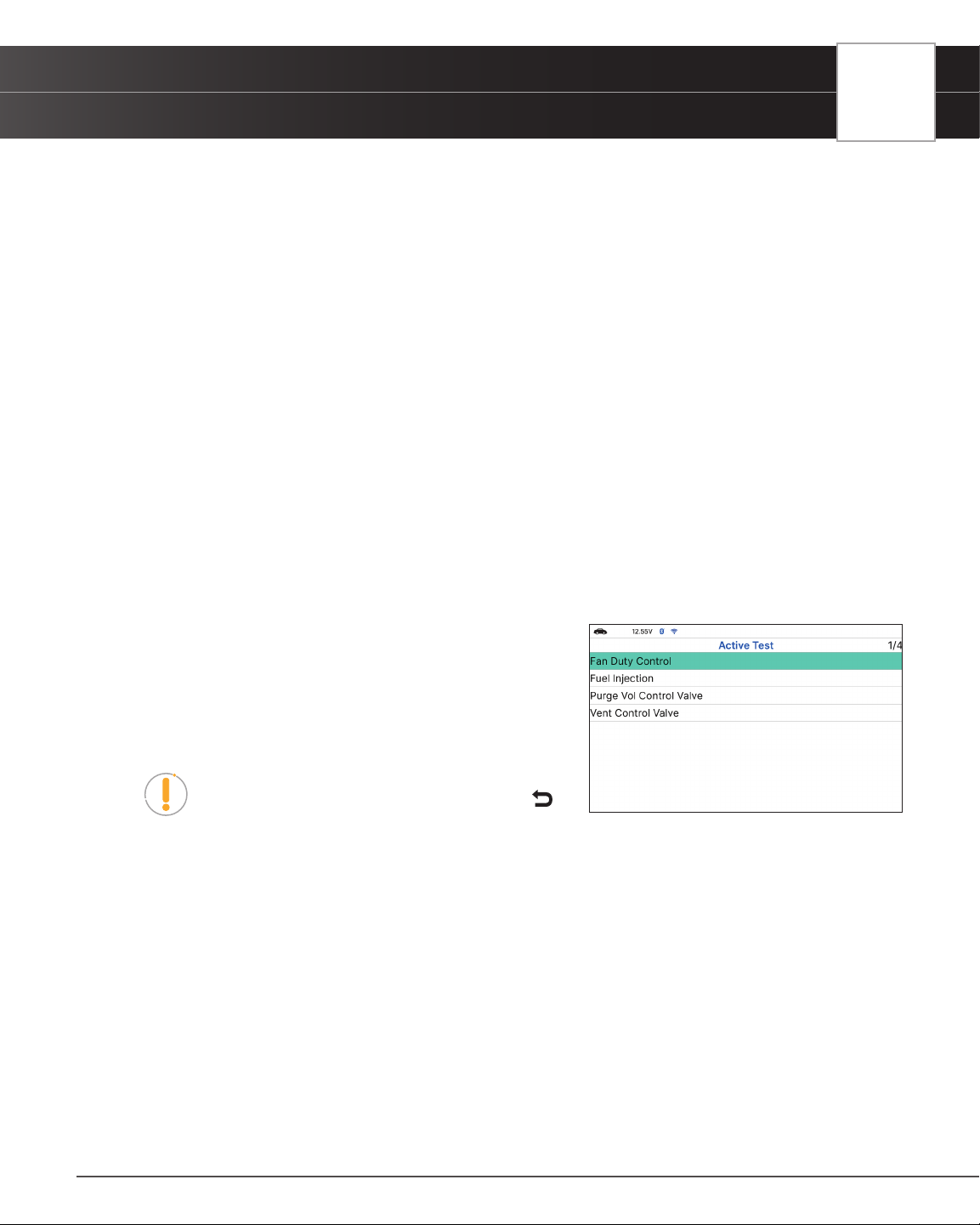
USING THE TABLET
OEM Diagnostics
Variable Intake Solenoid (Option) Test
1. Select Variable Intake Solenoid (Option) in the Active Test Menu, then press OK.
n A “conrmation” screen displays.
2. Select OK to continue.
n An “instructional” screen displays. Prepare the vehicle for the test as directed:
━ Engine RUN.
3. Select Start to begin the test.
n A “status” screen displays while the vehicle is being tested.
4. Select Stop to nish the test.
n A “results” screen displays.
5. Select OK to display the “conrmation” screen.
6. Select Cancel to return to the Active Test menu.
Nissan Active Tests
Depending on the vehicle under test, the Active Test menu provides access to one or more of the following tests on
Nissan vehicles:
Fan Duty Control
Fuel Injection
Purge Vol Control Valve
Vent Control Valve
NOTE: If an error occurs while performing any
function, an “advisory” message displays. Press
Back to return to the Active Test menu.
Fan Duty Control Test
1. Select Fan Duty Control in the Active Test menu, then press OK.
n An “instructional” screen displays. Prepare the vehicle for test as directed:
━ Ignition Switch On
2. Select Next to continue.
n The Fan Duty Control screen displays.
3. Select Increase or Decrease, as desired, then press OK.
n The screen refreshes to show the Result.
4. Repeat step 3 as desired.
43

44
USING THE TABLET
OEM Diagnostics
5. Select Back to return to the Active Test menu.
Purge Vol Control Valve Test
1. Select Purge Vol Control Valve in the Active Test menu, then press OK.
n An “instructional” screen displays. Prepare the vehicle for test as directed.
━ Engine: After Warning Up Above 158°F (70°C), run Engine at 1500-2000rpm.
2. Select Next to continue.
n An “Information” screen displays.
3. Select Next to continue.
n “The Purge Vol Control Valve” screen displays.
4. Select Down 10% or Up 10%, as desired, then press OK.
n The screen refreshes to show the test result.
5. Repeat step 3 as desired.
6. Press
Back to return to the Active Test menu.
Vent Control Valve Test
1. Select Vent Control Valve in the Active Test menu, then press OK.
n An “instructional” screen displays. Prepare the vehicle for test as directed:
━ Ignition Switch: ON (Engine Stopped)
2. Select Next to continue.
n An “Information” screen displays.
3. Select Next to continue.
n “The Purge Vol Control Valve” screen displays.
4. Select On or Off, as desired, then press OK.
n The screen refreshes to show the test result.
5. Repeat step 3 as desired.
6. Press
Back to return to the Active Test menu.
Toyota Active Tests
Depending on the vehicle under test, the Active Test Menu provides access to one or more of the following tests
on Toyota vehicles:
EGR Cut VSV
EGR Step Position / System
Inspection Mode
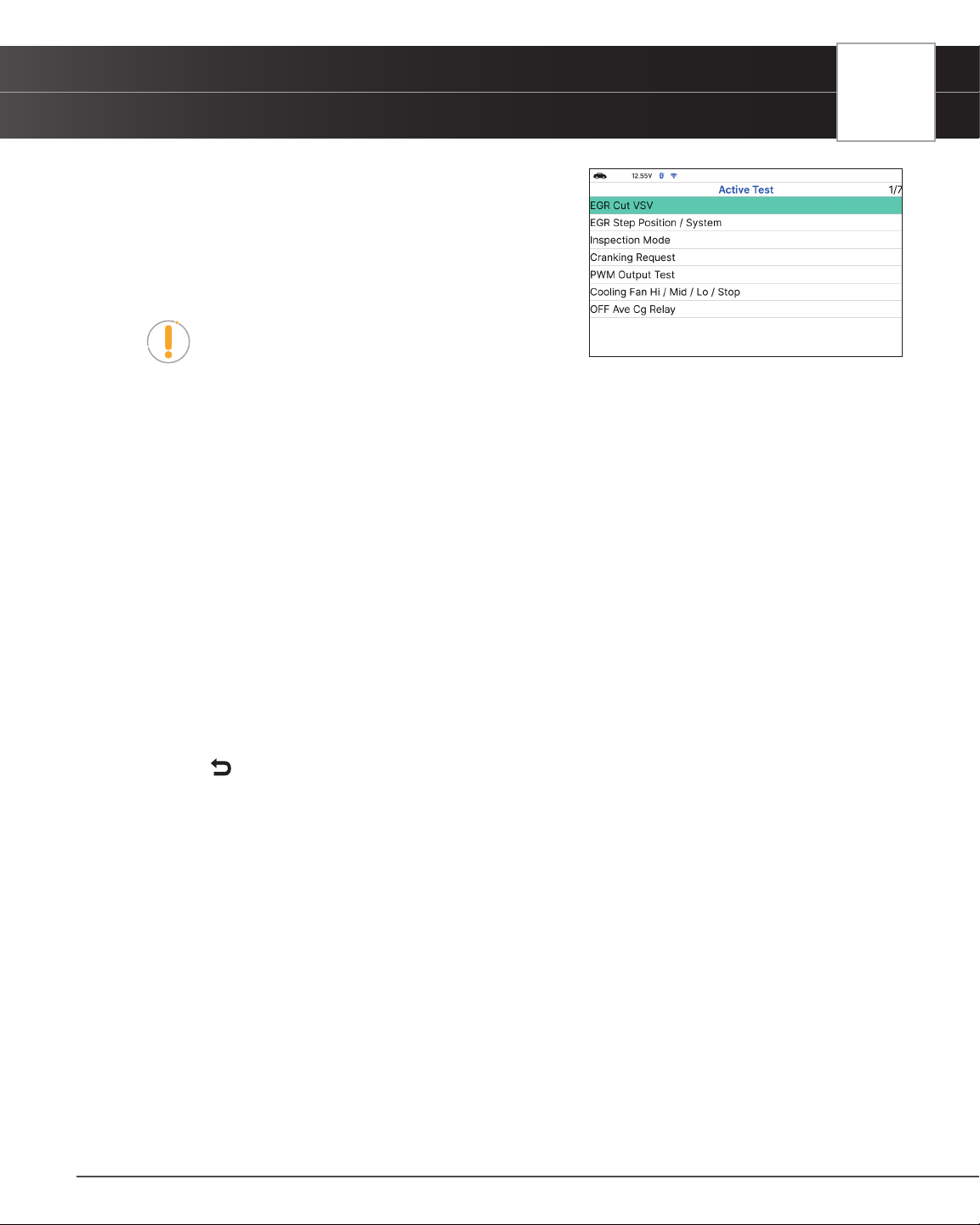
USING THE TABLET
OEM Diagnostics
Cranking Request
PWM Output Test
Cooling Fan Hi / Mid / Lo / Stop
OFF Ave Cg Relay
NOTE: If an error occurs while performing any
function, an “advisory” message displays. Press
Back to return to the Active Test Menu.
EGR Cut VSV Test
The EGR Cut VSV function lets you activate and deactivate the Exhaust Gas Recirculation (EGR) Vacuum
Switching Valve (VSV).
1. Select EGR Cut VSV in the Active Test Menu, then press OK.
n An “instructional” screen displays. Prepare the vehicle for test as directed:
━ Turn the ignition on. DO NOT start the engine.
━ Place the transmission in PARK.
2. Select Continue to proceed.
n The Control EGR Cut VSV screen displays.
3. Select On to activate the EGR Cut VSV. Select Off to deactivate the EGR Cut VSV.
n The display refreshes to show the results. Repeat as desired.
4. Press
Back to return to the Active Test Menu.
EGR Step Position / System Test
The EGR Step Position / System function lets you increase Exhaust Gas Recirculation (EGR) target position
through its full range (1% - 100%).
1. Select EGR Step Position / System in the Active Test Menu, then press OK.
n An “instructional” screen displays. Prepare the vehicle for test as directed:
━ Turn the ignition on. DO NOT start the engine.
━ Place the transmission in PARK.
2. Select Continue to proceed.
n The Control EGR Step Position / System screen displays.
3. Select Decrease to decrease the EGR target position. Select Increase to increase the EGR target position.
n The display refreshes to show the results. Repeat as desired.
45

46
USING THE TABLET
OEM Diagnostics
4. Press Back to return to the Active Test Menu.
Inspection Mode Test
The Inspection Mode function is used to check exhaust gases by engine intermittent prohibition or to allow use of
a chassis dynamometer by cutting Traction Control (TRC).
1. Select Inspection Mode in the Active Test Menu, then press OK.
n An “instructional” screen displays. Prepare the vehicle for test as directed:
━ Erase all DTCs from the vehicle’s computer.
━ Turn the ignition on. DO NOT start the engine.
━ Verify the Ready Light is OFF.
2. Select Next to continue.
n The Select Inspection Mode screen displays.
3. Select the desired inspection mode; 2WD for cutting TRC, 2WD for measuring Exhaust Gas, 4WD for cutting
TRC or 4WD for measuring Exhaust Gas.
n A “conrmation” screen displays.
4. Press
Back to return to the Active Test Menu.
5. Turn the ignition OFF to exit the inspection mode.
Cranking Request Test
The Cranking Request function lets you toggle the ECU mode from “normal” to “compression test” mode for
performing a compression test or other maintenance functions.
1. Select Cranking Request in the Active Test Menu, then press OK.
n An “instructional” screen displays. Prepare the vehicle for test as directed:
━ Turn the ignition on. DO NOT start the engine.
━ Verify the Ready Light is OFF.
2. Select Continue to proceed.
n The Set Mode screen displays.
3. Select On to place the ECU in “compression test” mod. Select Off to place the ECU in “normal” mode.
n The display refreshes to show the test results. Repeat as desired.
4. Press
Back to return to the Active Test Menu.
PWM Output Test
The PWM Output Test function lets you turn off current within the inverter when performing inverter maintenance.

USING THE TABLET
OEM Diagnostics
1. Select PWM Output Test in the Active Test Menu, then press OK.
n An “instructional” screen displays. Prepare the vehicle for test as directed:
━ Turn the ignition on. DO NOT start the engine.
━ Place the transmission in PARK.
━ Verify the Ready Light is OFF.
2. Select Continue to proceed.
n The Control PWM Output screen displays.
3. Select On to stop inverter current. Select Off to return to normal mode.
n The display refreshes to show the test results. Repeat as desired.
4. Press
Back to return to the Active Test Menu.
Cooling Fan Test
The Cooling Fan functions let you control operation of the battery cooling fan motor.
1. Select Cooling Fan Hi, Cooling Fan Mid, Cooling Fan Lo or Cooling Fan Stop in the Active Test Menu, as
desired, then press OK.
n An “instructional” screen displays. Prepare the vehicle for test as directed:
━ Place the transmission in NEUTRAL.
━ Verify the Ready Light is ON.
2. Select Continue to proceed.
n The Control Cooling Fan screen displays.
3. Select On to turn the cooling fan On. Select Off to turn the cooling fan off. It may take from 3 to 10 seconds
for cooling fan speed to change.
n The display refreshes to show the results. Repeat as desired.
4. Select
Back to return to the Active Test Menu.
OFF Ave Cg Relay Test
The OFF Ave Cg Relay function lets you activate and deactivate the THS charger adapter relay.
1. Select OFF Ave Cg Relay in the Active Test Menu, then press OK.
n An “instructional” screen displays. Prepare the vehicle for test as directed:
━ Place the transmission in NEUTRAL.
━ Verify the Ready Light is ON.
2. Select Continue to proceed.
n The Control Relay screen displays.
47
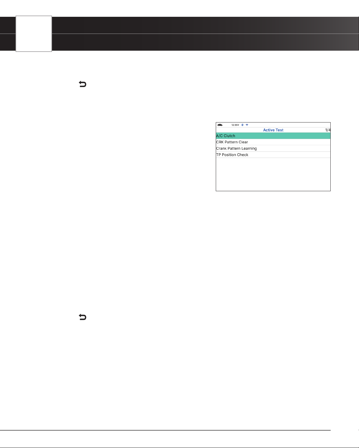
48
USING THE TABLET
OEM Diagnostics
3. Select On to activate the relay. Select Off to deactivate the relay.
n The display refreshes to show the test results. Repeat as desired.
4. Select
Back to return to the Active Test Menu.
Honda Active Tests
Depending on the vehicle under test, the Active Test menu
provides access to one or more of the following tests on Honda
vehicles:
A/C Clutch
CRK Pattern Clear
Crank Pattern Learning
TP Position Check A/C Clutch
A/C Clutch Manual Operation Test
1. Select A/C Clutch in the Active Test Menu, then press OK.
n An “instructional” screen displays. Prepare the vehicle for test as directed:
━ Place the transmission in NEUTRAL or PARK.
━ Turn the ignition on. DO NOT start the engine.
━ A/C Switch is OFF.
2. Select Next to proceed.
n The A/C Clutch Test screen displays.
3. Select On to activate the A/C Clutch. Select Off to deactivate the A/C Clutch.
n The display refreshes to show the test results. Repeat as desired.
4. Select
Back to return to the Active Test Menu.
CRK Pattern Clear
This clear command erases only CKP pattern data stored in the ECM/PCM. Use this clear command after repairing
a misre or replacing a CKP sensor. Afterward, do the ‘CKP pattern learn procedure’ to write the new CKP pattern
into the ECM/PCM.
1. Select Crank Pattern Clear in the Active Test Menu, then press OK.
n An “instructional” screen display. Prepare the vehicle for test as directed:
━ Place the transmission in NEUTRAL or PARK.
━ Turn the ignition on. DO NOT start the engine.
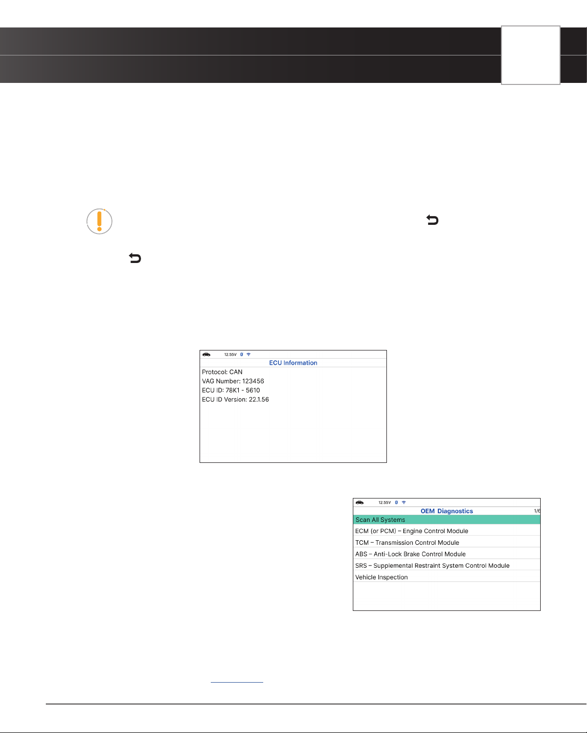
USING THE TABLET
OEM Diagnostics
━ Battery Voltage: 12V.
2. Select Next to proceed.
n A “Please waiting for clear….” message displays, followed by one or more “informational/
instructional” screens.
3. Perform test procedures as directed.
n When the process has competed, a conrmation message displays.
NOTE: If the process was not successful, an advisory message displays. Check
again the vehicle’s necessary conditions to re-perform this function. Select
Back
to return to the Active Test Menu.
4. Select
Back to return to the Active Test Menu.
Reading ECU Information
This function retrieves and displays the specic information for the tested control unit, including Protocol, ECU ID,
version number and other specications. The sample ECU Information screen displays as illustrated:
PERFORM A SCAN FOR INDIVIDUAL MODULES
From the OEM Diagnostics screen:
1. Select a module from the available list of modules, then press
OK. Proceed to step 4.
2. Select Scan All Systems, then press OK.
n The Module Selection displays.
3. Choose between Powertrain, Body, or Chassis modules you
wish to scan, then press OK.
n Screen shows list of available modules. Select the
system you would like to run, then press OK.
4. Depending on the modules selected, you can Read DTCs, Erase DTCs, view Live Data, perform Active Test
or read ECU Information.
Read DTCs – refer to [See page 34]
49

50
USING THE TABLET
OEM Diagnostics
Erase DTCs – refer to [See page 34]
Live Data – refer to [See page 35]
Active Test – refer to [See page 35]
ECU Information – refer to [See page 49]
VEHICLE INSPECTION
Performing a full vehicle scan ensures peace of mind for you and your customers. Many systems do not turn on a light
or places a message on the vehicle’s Diagnostic Information Center, so following this process can help uncover hidden
issues.
A good practice is to perform a pre-scan before any work is done to uncover all issues, then a post-scan once repairs
are complete to conrm the repairs were completed properly. Furthermore, several manufacturers mandate a pre- and
post-scan for all warranty work and insurance carriers require it for pre- and post-collision work.
n Emission Inspection Status - Indicates whether the vehicle is ready for an Emissions Test
(Smog Check) based on DTCs present, Freeze Frame data, Monitor Status, MIL (Check Engine
Light) status, State/Region, and Engine Type. Results are shown as “Pass”, “Fail” or “Warning”.
n Service Check – provides values for Engine Oil Level,
Oil Life Remaining, Brake Pad Life, Transmission
Temperature.
n TPMS - shows the status of the vehicle’s Tire Pressure
Monitoring System (TPMS) and the individual tire
pressures for all tires.
n Warning Light – conrms the ON or OFF status for
the vehicle’s ABS Dash Indicator and Airbag Dash
Indicator.
n System Fault – shows number of DTCs retrieved for all of the vehicle’s systems.
n System No Fault/Available – provides information on which vehicle systems are not reporting
any DTCs and/or it does not support reading DTCs.
n System No Response – shows the systems that the vehicle does not support.
DTC Detail – to view Denitions and status DTCs of all systems.
1. Follow the Scan All Systems steps to connect with the vehicle. [See page 33]
2. From the OEM Diagnostics screen, select the Vehicle Inspection button.
n The Select Business Report screen displays.
3. Choose the Business Report you wish to retrieve, then press OK.
n Diagnostic Report – Provides a report for OBD2 Data, MIL DTC additional Information, Scan
All Systems Data, and Vehicle Care.
n Customer Report – Provides a report for OBD2 Data, Scan All Systems Data, Service Check,
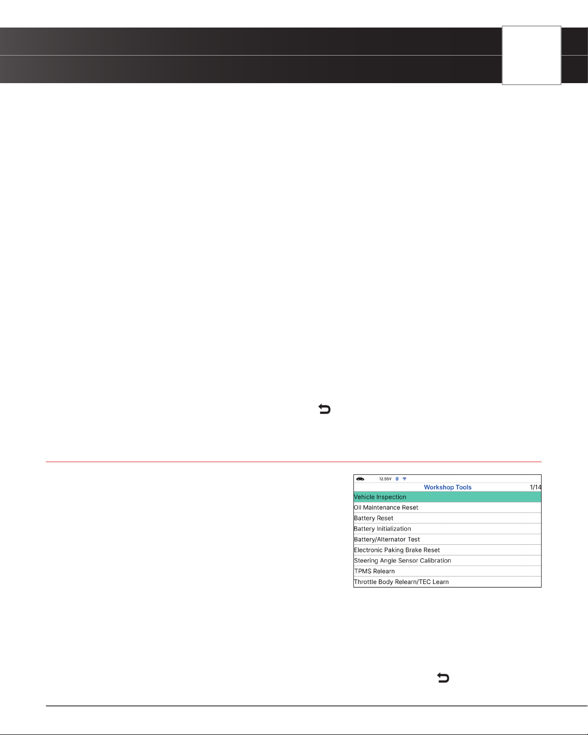
USING THE TABLET
Workshop Tools
Service Warning Lights, and Vehicle Care.
n Collision Industry Report – Provides a report for OBD2 Data, Scan All Systems Data, Service
Warning Lights, and Service Check.
4. Choose the report type you wish to view, then press OK.
n The PreScan – View the vehicle’s diagnostic report before making any repairs.
n The PostScan - View the vehicle’s diagnostic report after completing the repairs.
5. A “One moment please...” message displays, while the tablet scans all of the vehicle’s equipped modules.
n The tablet veries that it has a registered RSPRO account. If not, the screen displays a screen
requesting that the tablet be registered with an RSPRO account. Follow the steps to create your
account. To view the report result, press Cancel.
n The tablet also veries if its connected to a Wi-Fi Network or Bluetooth-connected to the RSPRO
app.
n It can take several minutes depending on the number of available systems available on the
vehicle being tested.
6. A “Submitting data…” message displays while this function is in progress.
7. Select Rescan, to get the most current diagnostic status for vehicle under test – particularly as you continue
to troubleshoot each individual control module.
n An “instructional” dialog displays to conrm selection.
n Select Yes to rescan the vehicle. Or, No to cancel.
8. When nished viewing all desired information, select
Back to return to the OEM Diagnostics menu.
WORKSHOP TOOLS
The WORKSHOP TOOLS tab allows you to perform several OEM /
dealership services, including Vehicle Inspection, Oil Maintenance
Reset, Battery Reset, Battery Initialization, EV/HEV/PHEV Battery
Health, Battery/Alternator Test, Electronic Parking Brake Reset,
and others. Access dealership level relearn procedures to complete
repairs or maintenance and much more.
OIL MAINTENANCE RESET
1. Select Oil Maintenance Reset on the Workshop Tools
screen.
n The Oil Maintenance Reset screen displays.
n An “instructional” dialog displays to conrm selection.
n Select Yes to continue. Or, No to cancel.
2. When the reset process has competed, a conrmation message displays. Select
Back to return to the
51

52
USING THE TABLET
Workshop Tools
Workshop Tools screen.
n If the Oil Maintenance Reset was not successful, an advisory message display.
NOTE: If the Tablet cannot reset the Oil Maintenance Light, an “instructional” dialog
displays, showing the manual procedures for resetting the indicator light. When
nished viewing the instructions, press
Back to return to the Workshop Tools
screen.
3. The Select Reset Method screen displays.
n If the vehicle under test does not have an Oil Maintenance Reset command function, the service
procedures will immediately display.
4. To perform the Oil Maintenance Reset by procedure, choose View Procedure.
n An “instructional” dialog displays, showing the manual procedures for resetting the indicator
light. When nished viewing the instructions, press
Back to return to the Workshop Tools.
5. To perform Oil Maintenance Reset by command, choose Perform Command.
n A “status” message displays while the Oil Maintenance Reset is in progress.
6. When the reset process has competed, a conrmation message displays.
n Choose
Back or Exit, as appropriate, to return to the Workshop Tools screen.
n If the Oil Maintenance Reset was not successful, an advisory message displays.
n To perform the Oil Maintenance Reset by procedure, choose View Procedure.
━ An “instructional” message displays, showing the manual procedures for resetting the
indicator light.
n If you do not wish to perform the Oil Maintenance Reset by procedure, choose Exit to return to
the Workshop Tools screen.
BATTERY RESET
You can use the Tablet to view the procedures for resetting the battery monitor system following a battery replacement.
1. Select Battery Reset on the Workshop Tools screen.
n The Battery Reset Procedures screen displays.
2. Select Continue, then press OK.
n The Battery Reset Procedures menu displays. The
menu provides access to General Information, and
procedures to be followed Battery Disconnection
Precautions, Battery Connection Precautions, and
Battery Connection Procedures.
NOTE: If battery reset procedures are not available,
an advisory message show. Choose
Back to return to the Workshop Tools
screen.

USING THE TABLET
Workshop Tools
3. Choose the procedure you wish to view, then press OK.
n The selected procedure displays.
4. When you have nished viewing the retrieved information, choose
Back to return to the Battery Reset
Procedures menu. Repeat step 3 to view additional procedures.
n When you have nished viewing all desired procedures, choose
Back to return to the
Workshop Tools.
BATTERY INITIALIZATION (Audi, BMW, Ford, Volkswagen, Volvo)
Follow these steps to perform a battery OBD reset service for Audi, BMW, Ford, Volkswagen, and Volvo models
only.
To perform battery reset OBD service (BMW / Ford / Volvo):
1. Select Battery Initialization on Workshop Tools screen.
n The Battery Reset OBD Service displays.
2. Select Next, then press OK.
n An “instructional” message display.
3. Follow the instructions provided to prepare the vehicle for battery reset OBD service. When all necessary
procedures have been performed, choose Next to continue.
n A “Live Data” screen displays, if applicable.
4. Choose Next to continue.
n A “One moment please…” message displays while battery reset is in process.
5. If the battery reset process is successful, a “Reset Complete” message displays.
n Choose Exit to return to the Workshop Tools screen.
n If the battery reset process is not successful, a “Reset Fail” message displays. Choose
Back to return to the Workshop Tools screen.
To perform battery reset OBD service (Audi / Volkswagen):
1. Tap Battery Initialization on Workshop Tools screen.
n The Battery Reset OBD Service displays.
2. Select Battery Reset OBD Service, then press OK.
n An “informational” screen display.
3. Choose Next to continue.
n A series of “instructional” screens display, directing you to enter reference information for the
battery (part number, manufacturer, serial number).
4. Choose Next as necessary to scroll the screen and enter the necessary information.
n A “conrmation” screen displays.
53

54
USING THE TABLET
Workshop Tools
n The screen shows the previously entered Battery part number, Battery manufacturer and
Battery serial number.
5. Select the desired option:
n To proceed with coding, select Carry Out Coding and press OK. Proceed to step 6.
n To re-enter battery reference information, select Repeat Input and press OK. Repeat steps 3
and 4.
n To cancel the battery reset process, select Cancel and press OK.
6. If battery coding was successful, a “conrmation” screen displays. Choose
Back to return to the Workshop
Tools screen.
n If battery coding was not successful, an “advisory” screen display. Choose Exit to return to the
Workshop Tools screen.
STEERING ANGLE SENSOR (SAS) CALIBRATION
The Steering Angle Sensor Calibration function is available for BMW, Chrysler, Ford, GM, Honda, Hyundai,
Mitsubishi, Nissan, Subaru, Toyota, Volkswagen, and Volvo vehicles only. Calibration procedures vary between
vehicle makes and models.
NOTE: If an error occurs while performing calibration procedures, an “advisory”
message display. Choose Exit to return to the Workshop Tools screen.
1. Select Steering Angle Sensor Calibration in the Workshop Tools screen, then press OK.
n For some vehicles, a sub-menu displays. Select the desired option, then press OK. Proceed
to step 2.
NOTE: If SAS calibration is not supported by the vehicle under test, an “advisory”
message display. Choose
Back to return to the Workshop Tools screen.
2. A “One moment please…” message displays, followed by one or more “informational/ instructional” screens.
n Perform test procedures as directed. Choose Next, as appropriate, to scroll to the next screen.
3. For some vehicles, “status” screens display as each phase of the calibration procedure is successfully completed.
Choose Next, as appropriate, to scroll to the next screen.
n A “results” screen displays when the calibration procedure has completed.
4. Choose
Back to return to the Workshop Tools screen.
ELECTRONIC PARKING BRAKE (EPB) RESET
EPB Reset procedures vary between vehicle makes and models.
NOTE: If an error occurs while performing calibration procedures, an “advisory”
message display. Choose Exit to return to the Workshop Tools screen.
USING THE TABLET
Workshop Tools
1. Select EPB Reset in the Workshop Tool screen, then press OK.
n A “One moment please…” message displays.
n For some vehicles, one or more sub-menus display. Select the desired module and/or option,
as appropriate, then press OK. Proceed to step 2.
NOTE: If EPB reset is not supported by the vehicle under test, an “advisory”
message displays. Choose
Back to return to the Workshop Tools screen.
2. One or more “informational/instructional” screens display.
n Perform test procedures as directed. Choose Next, as appropriate, to scroll to the next screen.
3. For some vehicles, “status” screens display as each phase of the calibration procedure is successfully completed.
Choose Next, as appropriate, to scroll to the next screen.
n A “One moment please…” message displays while the procedure is in process.
n A “results” screen displays when the calibration procedure has completed.
NOTE: If the procedure is stopped due to a communication error, an “advisory”
message displays. Choose
Back to return to the Workshop Tools screen.
4. Choose
Back to return to the Workshop Tools screen.
DPF RESET (Except Chrysler, General Motors, Nissan, and Volkswagen)
NOTE: If the vehicle under test is not a diesel vehicle, an “advisory” message
displays. Choose
Back to return to the Workshop Tools screen.
1. Select Diesel Particulate Filter Reset in the Workshop Tools screen, then press OK.
n A “One moment please…” message displays, followed by the DPF Reset Menu.
2. Select DPF Regeneration Procedure, then press OK.
n The DPF Regeneration Procedure screen displays.
NOTE: If the vehicle under test does not support DPF Regeneration Procedure, an
“informational” screen displays the procedures for “passive” DPF regeneration.
Choose
Back to return to the DPF Reset Menu.
3. Choose Next to continue.
n An “informational” screen displays the procedures for “passive” or “active” DPF regeneration,
as applicable. Choose
Back to return to the DPF Reset Menu.
4. To nish, choose Back to return to the DPF Reset Menu, then choose Back to return to the Workshop Tools
screen.
55

56
USING THE TABLET
Workshop Tools
DPF RESET (Chrysler)
1. Select Diesel Particulate Filter Reset in the Workshop Tools screen, then press OK.
n A “One moment please…” message displays, followed by the Diesel Particulate Filter Reset
menu.
2. Select the desired option, then press OK.
n An “instructional” screen displays. Prepare the vehicle for test as directed.
3. Choose Yes to continue.
n A series of “status” screens display while the routine is in process.
n A “conrmation” screen displays when the routine is completed.
NOTE: If the routine does not complete successfully, an “advisory” message display.
Choose Close to return to the Diesel Particulate Filter Reset menu.
4. Choose Finish to return to the Diesel Particulate Filter Reset menu, then choose
Back to return to the
Workshop Tools screen.
DPF RESET (General Motors)
1. Select Diesel Particulate Filter Reset in the Workshop Tools screen, then press OK.
n A “One moment please…” message displays, followed by the Diesel Particulate Filter Reset
menu.
2. Select the desired option, then press OK.
n One or more “informational/instructional” screens displays.
3. Choose Next, as appropriate, to scroll to the next screen.
n For some vehicles, a “conrmation” screen display.
4. Select Reset, as appropriate.
n A “conrmation” or “results” screen displays when the routine is completed.
NOTE: If the routine does not complete successfully, an “advisory” message may
display. Choose End to return to the Diesel Particulate Filter Reset menu.
5. Choose Exit to return to the Diesel Particulate Filter Reset menu, then choose
Back to return to the Workshop
Tools.
DPF RESET (Nissan)
1. Select Diesel Particulate Filter Reset in the Workshop Tools screen, then press OK.
n An “instructional” screen displays. Prepare the vehicle for test as directed.
2. Choose Next to continue.
n A “status” screen displays while the routine is in process.
USING THE TABLET
Workshop Tools
n A “conrmation” screen displays when the routine is completed.
NOTE: If the routine does not complete successfully, an “advisory” message display.
Choose Exit to return to the Workshop Tools screen.
3. Choose End to return to the Workshop Tools screen.
DPF RESET (Volkswagen)
1. Select Diesel Particulate Filter Reset in the Workshop Tools screen, then press OK.
n A “One moment please…” message displays, followed by the Diesel Particulate Filter Reset
menu.
2. Select the desired option, then press OK.
n A series of “informational/instructional” screens display. Prepare the vehicle for test as directed.
NOTE: If the selected function is not supported by the vehicle under test, an
“advisory” message may display. Choose End to return to the Diesel Particulate
Filter Reset menu.
3. Choose Next, Continue, or Start, as appropriate, to proceed.
n One or more “status” screens may display while the routine is in process.
n A “conrmation” or “results” screen displays when the routine is completed.
NOTE: If the routine does not complete successfully, an “advisory” message may
display. Choose End to return to the Diesel Particulate Filter Reset menu.
4. Choose End to return to the Diesel Particulate Filter Reset menu, then choose
Back to return to the Workshop
Tools.
ABS BLEEDING
The ABS Bleeding function is available for BMW, Chrysler, Ford, GM, Honda, Hyundai/KIA, Mazda, Jaguar/
Landrover, Mercedes, Mitsubishi, Nissan, Subaru, Toyota, Volkswagen and Volvo. Procedures vary between
vehicle makes and models.
NOTE: If an error occurs while performing ABS bleeding procedures, an “advisory”
message display. Choose Exit or
Back, as necessary, to return to the Workshop
Tools screen.
1. Select ABS Bleeding in the Workshop Tools screen, then press OK.
n A “One moment please…” message may displays.
n Once complete a sub-menu displays. Select the desired option, then press OK. Proceed to
step 2.
2. One or more “informational/ instructional” screens display.
57
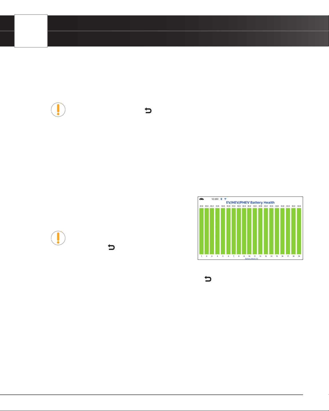
58
USING THE TABLET
Workshop Tools
n Perform test procedures as directed. Choose Next or Continue, as appropriate, to scroll to the
next screen.
3. For some vehicles, “status” screens display as each phase of the calibration procedure is successfully completed.
Choose Next or Continue, as appropriate, to scroll to the next screen.
n A “results” screen displays when the procedure has completed.
NOTE: If the procedure is stopped due to a communication error, an “advisory”
message display. Choose Exit or
Back, as necessary, to return to the Workshop
Tools screen.
4. Choose Exit or Back, as necessary, to return to the Workshop Tools screen.
EV/HEV/PHEV BATTERY HEALTH
Follow these steps to check the vehicle’s battery and alternator system (or hybrid/EV battery system) to ensure the
system is operating within acceptable limits.
1. Select EV/HEV/PHEV Battery Health, Battery/Alternator Test in the Workshop Tools screen.
n The EV/HEV/PHEV Battery Health, Battery/Alternator Test displays.
n If the vehicle is an electric or hybrid vehicle, the EV/
HEV/PHEV Battery Health screen shows a graphic
representation of the vehicle’s current state of charge
for all battery pack cells.
NOTE: If the Hybrid/EV Battery Test is not supported
by the vehicle under test, an “advisory” message
displays. Choose
Back to return to the Workshop
Tools screen.
n If the vehicle is not an electric or hybrid vehicle, the Battery/Alternator Test menu displays.
2. When you have nished viewing the retrieved information, choose
Back to return to the Workshop Tools
screen.
BATTERY / ALTERNATOR TEST
The Tablet can perform a check of the vehicle’s battery and alternator system to ensure the system is operating within
acceptable limits. Follow these steps to perform a battery check only, or an alternator system (battery and alternator)
check.
Perform a Battery Check Only
If the EV/HEV/PHEV Battery Health, Battery/Alternator Test is selected from the Workshop Tools screen and the
vehicle is not an electric or hybrid vehicle, the Battery/Alternator Test menu displays. Proceed to step 2.
1. Select Battery/Alternator Test, then press OK.

USING THE TABLET
Workshop Tools
n The Battery/Alternator Test Menu displays.
2. Select Battery Test, then press OK.
n An “instructional” message displays, showing the procedures to prepare the vehicle for the
battery check.
3. Prepare the vehicle for the battery check:
n Turn the engine off.
n Place the transmission in PARK or NEUTRAL and set the parking brake.
n Make a visual check of the battery’s condition. If the battery terminals are corroded or other
damage is present, clean or replace the battery as appropriate.
n For “unsealed” batteries, make sure the water level in each cell is above the battery plates.
n Turn the ignition on. DO NOT start the engine.
4. Choose Continue to proceed.
NOTE: If the engine is running, an advisory message will show. Turn the engine off,
then turn the ignition on. DO NOT start the engine. Press OK to continue.
n An “instructional” message displays.
5. Turn the vehicle’s headlights on, then choose Continue to proceed.
n A “countdown” message shows while the battery check is in process.
6. Turn the vehicle’s headlights off, then choose Continue to proceed.
n An “instructional” message is displayed.
━ If battery voltage is less than 12.1 volts, an advisory message shows. Choose
Home to
return to the Home Screen. Turn the ignition off and disconnect the Tablet from the vehicle.
Fully charge the battery, then repeat the battery check.
━ If the battery voltage is between 11.8 and 12.1 volts, a “Battery voltage is low, this may
affect the accuracy of the test results.” message displays
━ If battery voltage is greater than 12.1 volts, an “instructional” message displays.
7. Start the vehicle’s engine. Allow the engine to run for several seconds, then turn the engine off. Repeat for a
total of three “start/stop” cycles.
NOTE: If the Tablet did not detect “cranking status” for the vehicle’s engine, an
advisory message shows. Choose Retest to repeat the battery check or choose
Back to return to the Battery/Alternator Test menu.
8. When the battery check is complete, a results screen displays with the battery’s status.
9. Choose
Back to return to the Battery/Alternator Test menu.
View Battery Live Data
If the EV/HEV/PHEV Battery Health, Battery/Alternator Test is selected from the Workshop Tools screen and
59

60
USING THE TABLET
Workshop Tools
the vehicle is not an electric or hybrid vehicle, the Battery/Alternator Monitor menu displays. Proceed to step 2.
1. Select Battery/Alternator Test, then press OK.
n The Battery/Alternator Test menu displays.
2. Select Battery Live Data (12 Volts), then press OK.
n The Battery Live Data (12 Volts) screen displays.
3. When you are nished viewing the Battery Live Data (12 Volts), choose
Back to return to the Battery/
Alternator Test menu.
Perform a Charging System Check
If the EV/HEV/PHEV Battery Health, Battery/Alternator Test is selected from the Workshop Tools screen and
the vehicle is not an electric or hybrid vehicle, the Battery/Alternator Monitor menu displays. Proceed to step 2.
1. Select Battery/Alternator Test, then press OK.
n The Battery/Alternator Test menu displays.
2. Select Alternator Test, then press OK.
n An “instructional” message show.
3. Start and warm the engine to normal operating temperature. Turn on the headlights. Choose Continue to
proceed.
n An “instructional” message show.
4. Press the accelerator pedal to raise engine speed to 2000 RPM and maintain the engine speed.
n When engine speed is within the required range, the alternator test begins. A progress screen
shows.
n When the “countdown” timer expires, an “instructional” message displays.
5. Turn the vehicle’s headlights off and return the engine to idle speed.
n A “One moment please…” message displays while the test results are retrieved.
6. When the alternator check is complete, a results screen shows charging system voltage and indicates
whether the charging system is within acceptable limits.
7. Choose
Back to return to the Battery/Alternator Test menu.
View Alternator Live Data
If the EV/HEV/PHEV Battery Health, Battery/Alternator Test is selected from the Workshop Tools screen and
the vehicle is not an electric or hybrid vehicle, the Battery/Alternator Monitor menu displays. Proceed to step 2.
1. Select Battery/Alternator Test, then press OK.
n The Battery/Alternator Test menu displays.
2. Select Alternator Live Data, then press OK.
n The Alternator Live Data, screen displays.
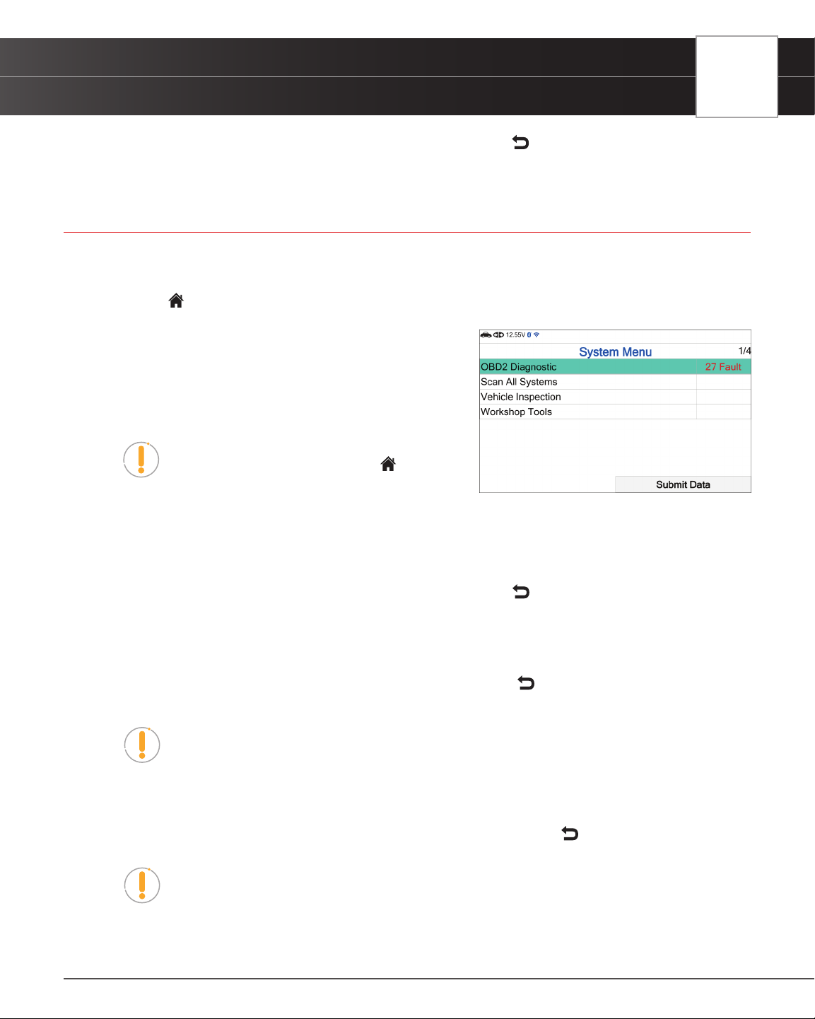
USING THE TABLET
Previous Vehicles
3. When you’ve concluded viewing the Alternator Live Data, choose Back to return to the Battery/Alternator
Test menu.
PREVIOUS VEHICLES
The Tablet stores the results of the most recent vehicle scans you have performed. The Previous Vehicles function
allows you to retrieve these historical scan records and view them as needed.
1. From the
Home screen, select the Previous Vehicle tab and press OK.
2. If more than one vehicle is stored in the Tablet’s memory, the
Vehicle Selection menu displays. Select the desired vehicle,
then press OK.
n The Memory System Menu displays and includes:
OBD2 Diagnostics, Scan All Systems, Vehicle
Inspection, and Workshop Tools.
NOTE: If there are no vehicles currently stored,
an advisory message displays. Press
Home to
return to the Home Screen.
3. Select OBD2 Diagnostics, then press OK.
n The Tablet displays the Memory OBD2 Diagnostics screen.
n The Memory OBD2 Diagnostics function allows you to review the available 10 modes of OBD2.
n Select the function you wish to view, then press OK. Choose
Back to return to the Memory
OBD2 Menu.
4. Or, select Workshop Tools, then press OK.
n The Tablet displays the Memory Workshop Tools listing.
n Select the procedure you wish to view, then press OK. Choose
Back to return to the Memory
System Menu.
NOTE: The Memory Workshop Tools function allows you to review only Oil
Maintenance Reset Procedures and Battery Reset Procedures.
5. Or, select Scan All Systems, then press OK.
n The Tablet displays the Memory Scan All Systems listing.
n Select the system you wish to view its DTCs, then press OK. Choose
Back to return to the
Memory System Menu.
NOTE: The Tablet only shows systems saved in memory mode.
6. Or, select Vehicle Inspection, then press OK.
n The Tablet displays the scan type report listing.
61
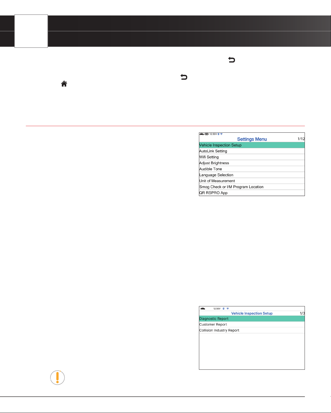
62
USING THE TABLET
Settings
n Select the scan type report you wish to view, then press OK. Choose Back to return to the
Memory System Menu.
7. When you have nished viewing the information, choose
Back to return to the Previous Vehicles screen or
press
Home to exit to the Home Screen.
n An “advisory” conrmation message displays.
n Select Yes to exit and return to the Home Screen. Or, select No to proceed.
SETTINGS
The Tablet lets you make several adjustments and settings to
congure it to your particular needs. The following functions can be
performed:
Vehicle Inspection Setup
AutoLink Setting
Wi Setting
Adjust Brightness
Audible Tone
Language Selection
Unit of Measurement
Smog Check or I/M Program Location
QR RSPRO App
QR RSPRO App Setting
Version Information
Update
VEHICLE INSPECTION SETUP
1. Select Vehicle Inspection Setup in the Settings menu, then
press OK.
n The Vehicle Inspection Setup screen displays.
2. Select the type of report you wish to setup, then press OK.
n The Report Selection screen displays.
n Select or unselect functions as desired, then press
OK.
NOTE: The OBD2 Diagnostics (DTCs, Monitor, Freeze Frame Data) status is always
ON; this function cannot be turned OFF.
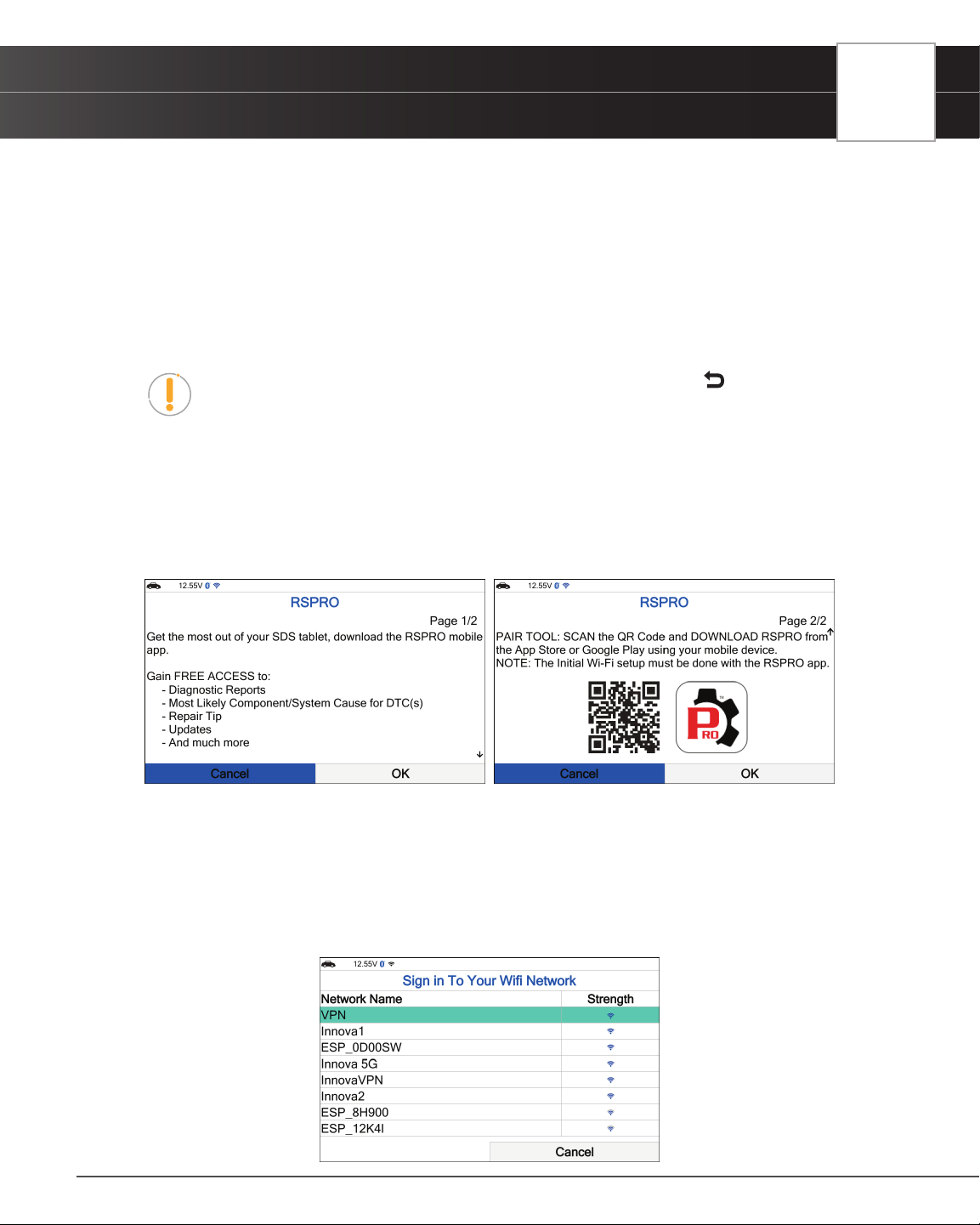
USING THE TABLET
Settings
3. Select Save to save your changes and auto-return to the Report Selection screen.
n To exit and not proceed, select Cancel to return to the Report Selection screen.
AUTOLINK SETTING
1. Select AutoLink Setting in the Settings menu, then press OK.
n The AutoLink Setting screen displays.
2. Select On or Off as desired.
NOTE: To return to the Settings menu without making changes, press the
Back
button.
WI-FI SETTING
1. Select Wi-Fi Setting in the Settings menu, then press OK.
n The tablet veries if it is registered to the RSPRO app. If not, the screen displays the information
requesting that the tablet registered to the RSPRO app.
n If the tablet registered with the RSPRO app, the Wi-Fi Setting screen displays.
n If you are currently connected to a Wi-Fi network, the Network Name is shown “Connected”
under the Strength column; if not, it shows the Wi-Fi icon.
2. To change or connect to a Network, choose the desired network name, then press OK.
n The Sign in To Your Wi-Fi Network dialog displays.
63
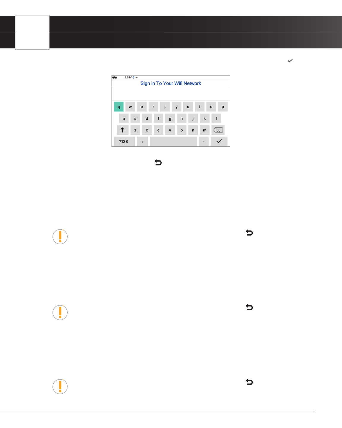
64
USING THE TABLET
Settings
3. Enter the Wi-Fi network password using the keyboard. Once the password has been entered, tap the button to
save your changes and complete your connection.
n To select a different network, press
Back to cancel your changes and return to the Sign in
To Your Wi-Fi Network dialog screen.
ADJUSTING DISPLAY BRIGHTNESS
1. Select Adjust Brightness in the Settings menu, then press OK.
n The Adjust Brightness screen displays.
2. Press UP and DOWN to make the display lighter or darker.
NOTE: To return to the Settings menu without making changes, press the
Back
button.
ENABLING/DISABLING THE AUDIBLE TONE
1. Select Audible Tone in the Settings menu, then press OK.
n The Audible Tone screen displays.
2. Select On or Off as desired.
NOTE: To return to the Settings menu without making changes, press the
Back
button.
SELECTING THE DISPLAY LANGUAGE
1. Select Language Selection in the Settings menu, then press OK.
n The Language Selection screen displays.
2. Select the desired display language (English, Spanish, French), the tablet will automatically save your changes.
NOTE: To return to the Settings menu without making changes, press the
Back
button.
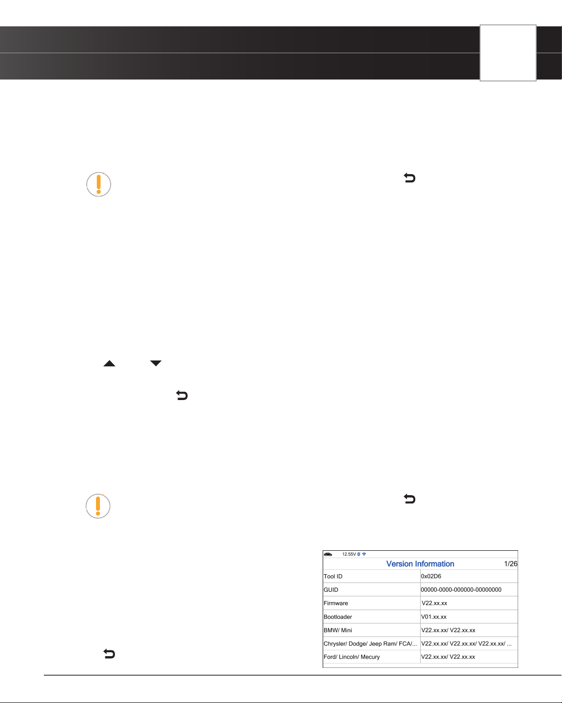
USING THE TABLET
Settings
SETTING THE UNIT OF MEASUREMENT
1. Select Unit of Measurement in the Settings menu, then press OK.
n The Unit of Measurement screen displays.
2. Select the desired unit of measurement (Standard or Metric), the tablet will automatically save your changes.
NOTE: To return to the Settings menu without making changes, press the
Back
button.
SMOG CHECK OR I/M PROGRAM LOCATION
1. Select Smog Check or I/M Program Location in the Settings menu, then press OK.
n The Smog Check or I/M Program Location displays.
2. Select the desired U.S. state.
VIEWING THE APP QR CODE - RepairSolutionsPRO™
1. Select QR RSPRO App in the Settings menu, then press OK.
n The QR RSPRO App screen displays.
2. Press
UP and DOWN to navigate through the options.
n Using a mobile device, scan the QR Code to download the RepairSolutionsPRO App.
n To exit, choose
Back to return to the Settings menu.
SETTING THE QR RepairSolutionsPRO APP MODE
1. Select QR RSPRO App Setting in the Settings menu, then press OK.
n The QR RSPRO App Setting screen displays.
2. Select Enable or Disable as desired.
NOTE: To return to the Settings menu without making changes, press the
Back
button.
VIEWING THE VERSION INFORMATION
1. Select Version Information in the Settings menu, then
press OK.
n The Version Information screen displays.
n The screen shows the tablet’s Tool ID, GUID,
current Firmware version, Bootloader version
and database version for the specic Make.
2. Press
Back to return to the Settings menu.
65
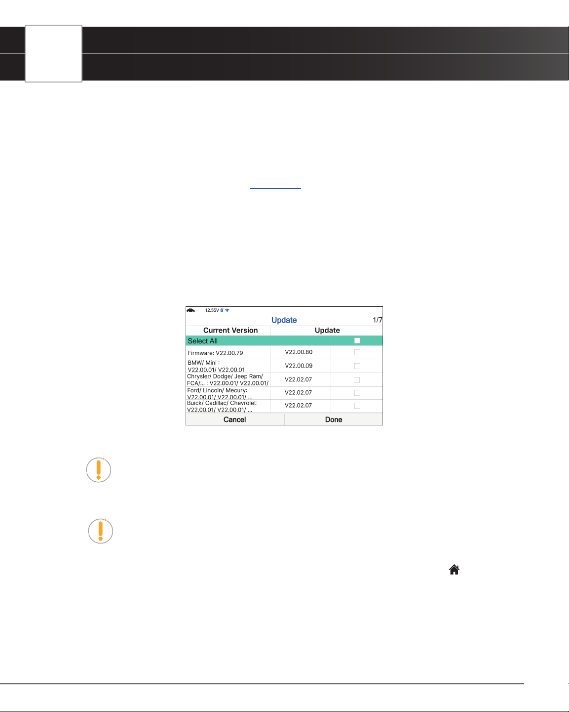
66
USING THE TABLET
Settings
UPDATING THE TABLET
1. Select Update in the Settings menu, then press OK.
n Verify that the tablet is connect to a Wi-Fi Network.
n If the tablet is not connected to a Wi-Fi network, an alert message displays “Please connect to
Wi-Fi to continue”. Select Cancel, then press OK to return to Settings menu or select Connect
Wi-Fi to connect a Wi-Fi network [
See page 63].
n If the Tablet fails to establish communication, the screen displays a notice. Select Cancel, then
press OK to return to Settings menu or select Try Again, then press OK to try to reconnect.
2. A “One moment please…” message displays while the update function is in progress.
n If an Update is not available, an advisory message displays. Select Close, then press OK to
return to the Settings menu.
3. The screen displays the current rmware version and the most recent database version for the specic make.
n Select or unselect any available updates as desired.
n If you want to update all available versions, check the Select All box.
NOTE: The check-box is only available for database that has an update. If an update
is not available, the check-box will be dim and unavailable to select.
4. Select Done, then press OK to perform the update. Select Cancel if you want to exit update.
NOTE: Avoid any power or Wi-Fi interruptions during the update process. Make sure
the tablet is plugged in with the provided power supply charger and the tablet has a
good Wi-Fi connection.
5. Once the update process is completed, select Close to return to Settings menu, or press the
Home button to
return to Home Screen.
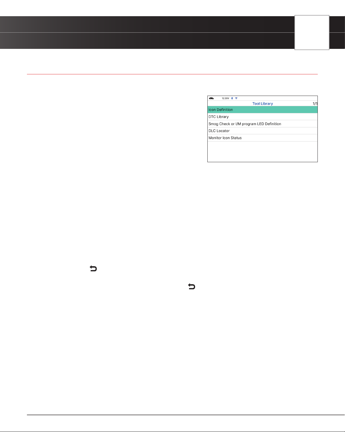
USING THE TABLET
Tool Library
TOOL LIBRARY
Tool Library contains valuable reference information for the Tablet. The following functions are available:
n Icon Denition – Shows the full names for the I/M
MONITOR STATUS icons shown and descriptions of
informational icons on the Tablet’s display.
n DTC Library – Provides access to libraries of OBD2
DTC denitions.
n Smog Check or I/M Program LED Denition -
Provides descriptions of the meaning of the Tablet
SYSTEM STATUS LEDs.
n DLC Locator - Use this search function to quickly nd
the location of the Data Link Connector (DLC) for a specied vehicle.
n Monitor Icon Status - Denes the icon monitor status’ color coding and provides tips on how
to proceed.
ICON DEFINITION
1. Select Icon Denition in the Tool Library menu, then press OK.
n The Icon Denition displays.
2. Select the type of icons you wish to view – Spark Ignition Monitors, Compression Ignition Monitors, or Tool
Icons, the press OK.
n The screen shows a list of Monitor for the selected category.
n Choose
Back to return to the Icon Denition menu. If desired, repeat step 2 to view additional
icon denitions.
3. When you have nished viewing the descriptions, choose
Back to return to the Icon Denition menu.
DTC LIBRARY
1. From the Tool Library menu, select DTC Library, then press OK.
n The Select Library screen displays.
2. Select OBD2 Library, then press OK.
n The Select Manufacturer screen displays.
3. Select the desired vehicle manufacturer, then press OK.
n A conrmation message shows.
━ If the correct manufacturer is not shown, choose No to return to the list of vehicle
manufacturers.
━ If the correct manufacturer is shown, choose Yes.
67
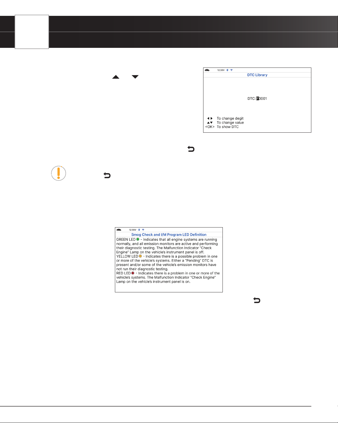
68
USING THE TABLET
Tool Library
4. The Enter DTC screen displays.
n The screen shows the code “P0001,” with the “P”
highlighted. Press
Up / Down, as necessary, to
scroll to the desired DTC type (P=Powertrain,
U=Network, B=Body, C=Chassis), then choose Next
Digit.
n The selected character displays solid, and the next
character is highlighted.
5. Select the remaining digits in the DTC in the same way. When
you have selected all the DTC digits, press OK to view the DTC
denition.
6. When you have nished viewing the DTC denition, choose
Back, to return to the Enter DTC screen to search
for additional DTCs.
NOTE: If a denition for the DTC you entered is not available, an advisory message
show. Choose
Back to return to the Enter DTC screen and enter additional DTCs.
SMOG CHECK OR I/M PROGRAM LED DEFINITIONS
1. From the Tool Library menu, select Smog Check or I/M Program LED Denition, then press OK.
n The Smog Check or I/M Program LED Denition screen displays.
2. When you have nished viewing the Smog Check or I/M Program LED Denition, choose
Back to return to Tool
Library menu.
USING THE DLC LOCATOR
1. Select DLC Locator in the Tool Library menu, then press OK.
n The Select Vehicle Model Year screen displays.
2. Select the desired vehicle model year, then press OK.
n The Select Vehicle Manufacturer screen displays.
3. Select the desired vehicle manufacturer, then press OK.
n The Select Vehicle Model screen displays.
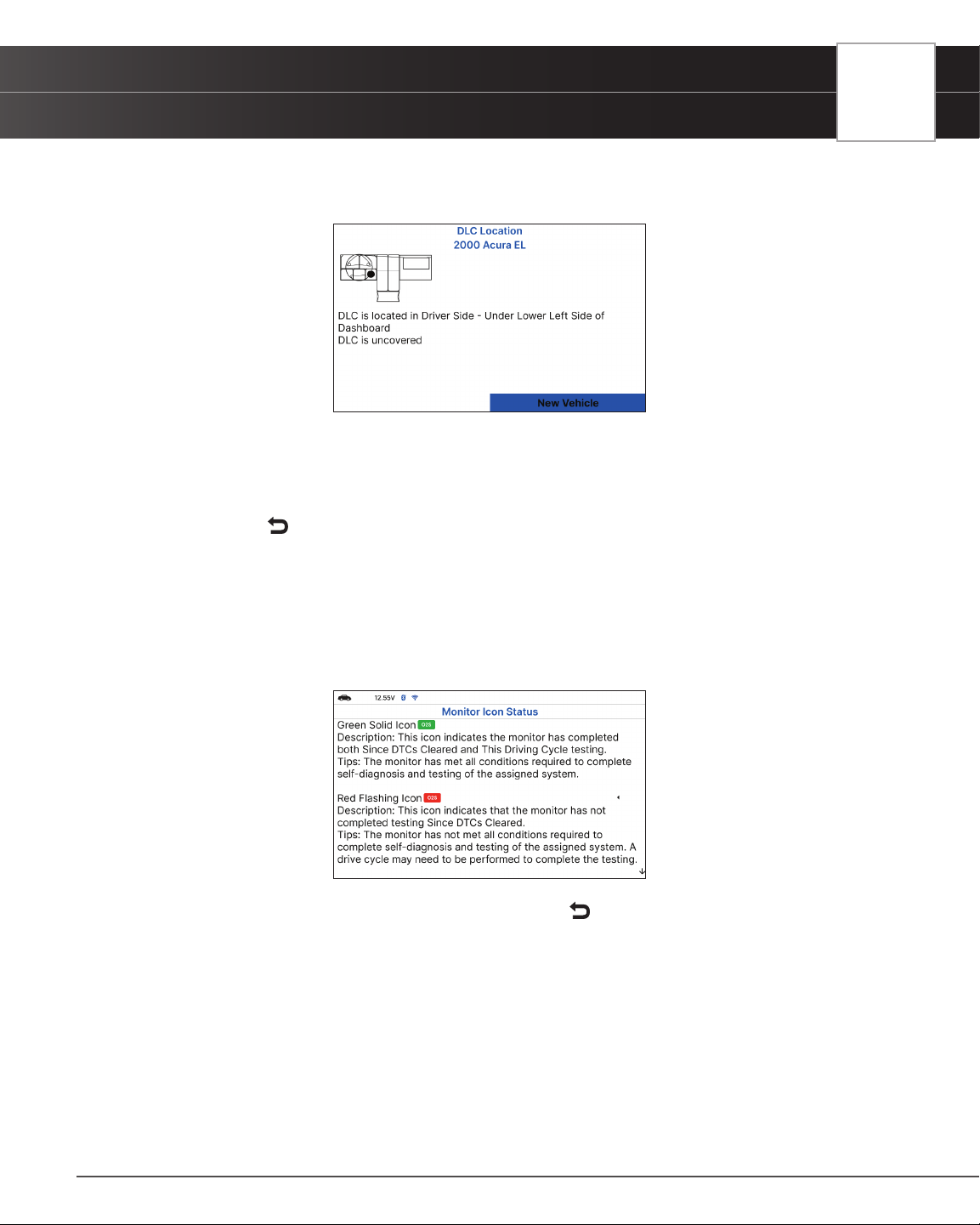
USING THE TABLET
Tool Library
4. Select the desired model, then press OK.
n The DLC Location screen for the selected vehicle displays.
n The DLC Location screen shows the selected vehicle make and model, a description of the
DLC location and whether the DLC is “covered” or “uncovered,” and includes a picture of the
DLC location.
5. When you have nished viewing the DLC location, choose New Vehicle (to view the DLC location for another
vehicle) or choose
Back to return to the Tool Library menu.
ICON MONITOR STATUS
Denes the icon monitor status color coding and provides tips on how to proceed.
1. Select Monitor Icon Status in the Library menu, then press OK.
n The Monitor Icon Status dialog displays.
2. When you have nished viewing the Monitor Icon Status, press Back to return to Tool Library menu.
69

70
WARRANTY+ CUSTOMER SERVICE
Limited Warranty
WARRANTY+ CUSTOMER SERVICE
LIMITED WARRANTY
The Manufacturer warrants to the original purchaser that this unit is free of defects in materials and workmanship under
normal use and maintenance for a period of one (1) year from the date of original purchase.
If the unit fails within the one (1) year period, it will be repaired or replaced, at the Manufacturer’s option, at no charge,
when returned prepaid to the Service Center with Proof of Purchase. The sales receipt may be used for this purpose.
Installation labor is not covered under this warranty. All replacement parts, whether new or remanufactured, assume
as their warranty period only the remaining time of this warranty.
This warranty does not apply to damage caused by improper use, accident, abuse, improper voltage, service, re,
ood, lightning, or other acts of God, or if the product was altered or repaired by anyone other than the Manufacturer’s
Service Center.
The Manufacturer, under no circumstances shall be liable for any consequential damages for breach of any written
warranty of this unit. This warranty gives you specic legal rights, and you may also have rights, which vary from state
to state. This manual is copyrighted with all rights reserved. No portion of this document may be copied or reproduced
by any means without the express written permission of the Manufacturer. THIS WARRANTY IS NOT TRANSFERABLE.
For service, send via U.P.S. (if possible) prepaid to Manufacturer. Allow 3-4 weeks for service/repair.
CUSTOMER SERVICE
Our ASE Certied technical staff is here to help if you have any questions or require service. For information on
UPDATES and OPTIONAL ACCESSORIES, please contact your local store, distributor or Innova’s Service Center.
USA & Canada: (800) 544-4124
Monday through Friday: 6:00 AM to 6:00 PM PST
All others: (714) 241-6802
Monday through Friday: 6:00 AM to 6:00 PM PST
FAX: (714) 241-3979 (24 Hr.)
Web:
www.innova.com

GLOSSARY
OBD2 Terminology
GLOSSARY
OBD2 TERMINOLOGY
The following terms and their denitions are related to OBD2 systems.
n Powertrain Control Module (PCM) - The PCM is the OBD2 accepted term for the vehicle’s “on-board
computer.” In addition to controlling the engine management and emissions systems, the PCM also
participates in controlling the powertrain (transmission) operation. Most PCMs also have the ability to
communicate with other computers on the vehicle (ABS, ride control, body, etc.).
n Monitor - Monitors are “diagnostic routines” programmed into the PCM. The PCM utilizes these programs
to run diagnostic tests, and to monitor operation of the vehicle’s emissions-related components or
systems to ensure they are operating correctly and within the vehicle’s manufacturer specications.
Currently, up to fteen Monitors are used in OBD2 systems. Additional Monitors will be added as the
OBD2 system is further developed.
NOTE: Not all vehicles support all fteen Monitors
n Enabling Criteria - Each Monitor is designed to test and monitor the operation of a specic part of the
vehicle’s emissions system (EGR system, oxygen sensor, catalytic converter, etc.). A specic set of
“conditions” or “driving procedures” must be met before the computer can command a Monitor to run
tests on its related system. These “conditions” are known as “Enabling Criteria.” The requirements and
procedures vary for each Monitor. Some Monitors only require the ignition key to be turned “On” for them
to run and complete their diagnostic testing. Others may require a set of complex procedures, such
as, starting the vehicle when cold, bringing it to operating temperature, and driving the vehicle under
specic conditions before the Monitor can run and complete its diagnostic testing.
n Complete / Incomplete - The terms “Complete” or “Incomplete” are used throughout this manual.
“Complete,” means the PCM has commanded a particular Monitor to perform the required diagnostic
testing on a system to ensure the system is operating correctly (within factory specications). The term
“Incomplete” means the PCM has not yet commanded a particular Monitor to perform diagnostic testing
on its associated part of the emissions system.
n Trip - A Trip for a particular Monitor requires that the vehicle is being driven in such a way that all the
required “Enabling Criteria” for the Monitor to run and complete its diagnostic testing are met. The
“Trip Drive Cycle” for a particular Monitor begins when the ignition key is turned “On.” It is successfully
completed when all the “Enabling Criteria” for the Monitor to run and complete its diagnostic testing
are met by the time the ignition key is turned “Off.” Since each of the fteen monitors is designed to
run diagnostics and testing on a different part of the engine or emissions system, the “Trip Drive Cycle”
needed for each individual Monitor to run and complete varies.
n OBD2 Drive Cycle - An OBD2 Drive Cycle is an extended set of driving procedures that takes into
consideration the various types of driving conditions encountered in real life. These conditions may
include starting the vehicle when it is cold, driving the vehicle at a steady speed (cruising), accelerating,
etc. An OBD2 Drive Cycle begins when the ignition key is turned “On” (when cold) and ends when the
71

72
GLOSSARY
OBD2 Monitors
vehicle has been driven in such a way as to have all the “Enabling Criteria” met for all its applicable
Monitors. Only those trips that provide the Enabling Criteria for all Monitors applicable to the vehicle to
run and complete their individual diagnostic tests qualify as an OBD2 Drive Cycle. OBD2 Drive Cycle
requirements vary from one model of vehicle to another. Vehicle manufacturers set these procedures.
Consult your vehicle’s service manual for OBD2 Drive Cycle procedures.
NOTE: Do not confuse a “Trip” Drive Cycle with an OBD2 Drive Cycle. A “Trip” Drive
Cycle provides the “Enabling Criteria” for one specic Monitor to run and complete
its diagnostic testing. An OBD2 Drive Cycle must meet the “Enabling Criteria” for all
Monitors on a particular vehicle to run and complete their diagnostic testing.
n Warm-up Cycle - Vehicle operation after an engine off period where engine temperature rises at least
40°F (22°C) from its temperature before starting, and reaches at least 160°F (70°C). The PCM uses
warm-up cycles as a counter to automatically erase a specic code and related data from its memory.
When no faults related to the original problem are detected within a specied number of warm-up cycles,
the code is erased automatically.
OBD2 MONITORS
To ensure the correct operation of the various emissions-related components and systems, a diagnostic program was
developed and installed in the vehicle’s on-board computer. The program has several procedures and diagnostic
strategies. Each procedure or diagnostic strategy is made to monitor the operation of, and run diagnostic tests on, a
specic emissions-related component or system. These tests ensure the system is running correctly and is within the
manufacturer’s specications. On OBD2 systems, these procedures and diagnostic strategies are called “Monitors.”
Currently, fteen Monitors are supported by OBD2 systems. Additional monitors may be added because of Government
regulations as the OBD2 system grows and matures. Not all vehicles support all fteen Monitors. Additionally, some
Monitors are supported by “spark ignition” vehicles only, while others are supported by “compression ignition” vehicles
only.
Monitor operation is either “Continuous” or “Non-Continuous,” depending on the specic monitor.
CONTINUOUS MONITORS
Three of these Monitors are designed to constantly monitor their associated components and/or systems for proper
operation. Continuous Monitors run constantly when the engine is running.
= Comprehensive Component Monitor
= Misre Monitor
= Fuel System Monitor
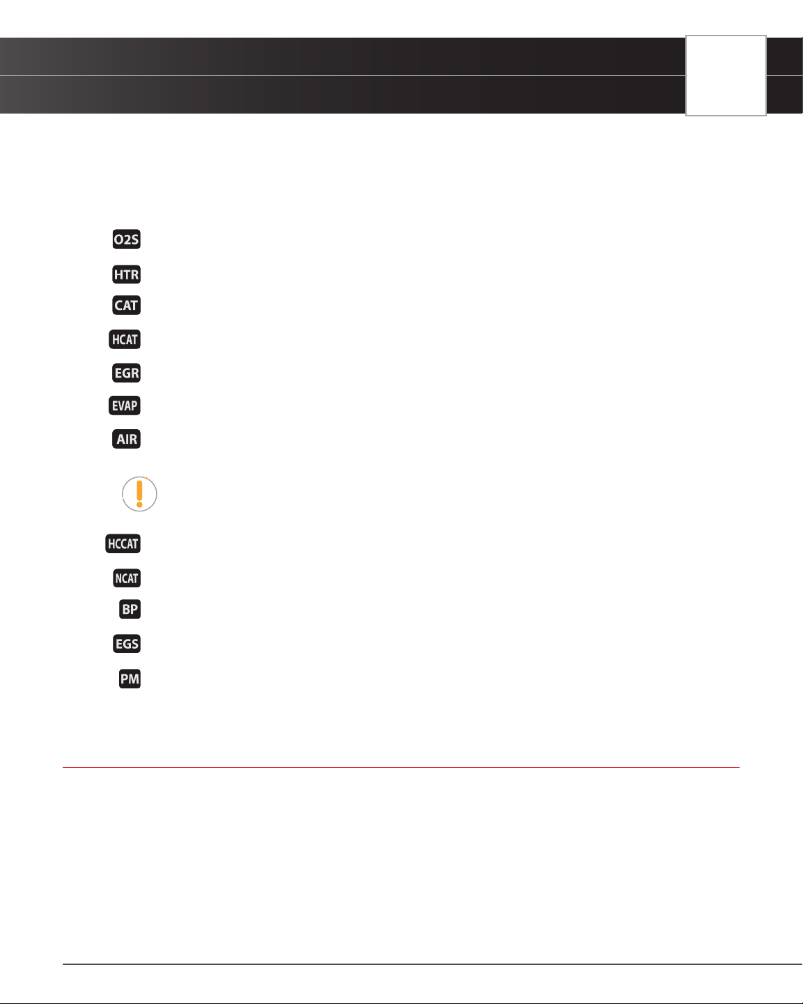
GLOSSARY
Additional Terminology + Acronyms
NON-CONTINUOUS MONITORS
The other twelve Monitors are “non-continuous” Monitors. “Non-continuous” Monitors perform and complete their
testing once per trip.
= Oxygen Sensor Monitor
= Oxygen Sensor Heater Monitor
= Catalyst Monitor
= Heated Catalyst Monitor
= EGR (Exhaust Gas Recirculation) System Monitor
= EVAP System Monitor
= Secondary Air System Monitor
NOTE: The following Monitors became standard beginning in 2010. The majority of
vehicles produced before this time will not support these Monitors.
= NMHC (Non-Methane Hydrocarbon Converting) Catalyst Monitor
= NOx/SCR Aftertreatment Monitor
= Boost Pressure System Monitor
= Exhaust Gas Sensor Monitor
= PM (Particulate Matter) Filter Monitor
ADDITIONAL TERMINOLOGY + ACRONYMS
n ABS = Anti-Lock Brakes
n DLC = Data Link Connector (vehicle’s data port)
n DTC = Diagnostic Trouble Codes
n KOEO = Key On, Engine Off
n KOER = Key On, Engine Running
n MIL = Malfunction Indicator Lamp (Check Engine Light)
73

74
GLOSSARY
Additional Terminology + Acronyms
n OBD = On Board Diagnostics
n OBD2 / OBD II = On Board Diagnostics, Second Generation
n OEM = Original Equipment Manufacturer
n PID = Parameter Identication Data
n SRS = Safety Restraint System
n TPMS = Tire Pressure Monitoring System
n TSBs = Technical Service Bulletins

Copyright © 2023 IEC. All Rights Reserved.
v.1.00
Innova Electronics Corp.
17352 Von Karman Ave.
Irvine, CA 92614