Loading ...
Loading ...
Loading ...
TROUBLE DIAGNOSIS
EC-919
[YD (WITH EURO-OBD)]
C
D
E
F
G
H
I
J
K
L
M
A
EC
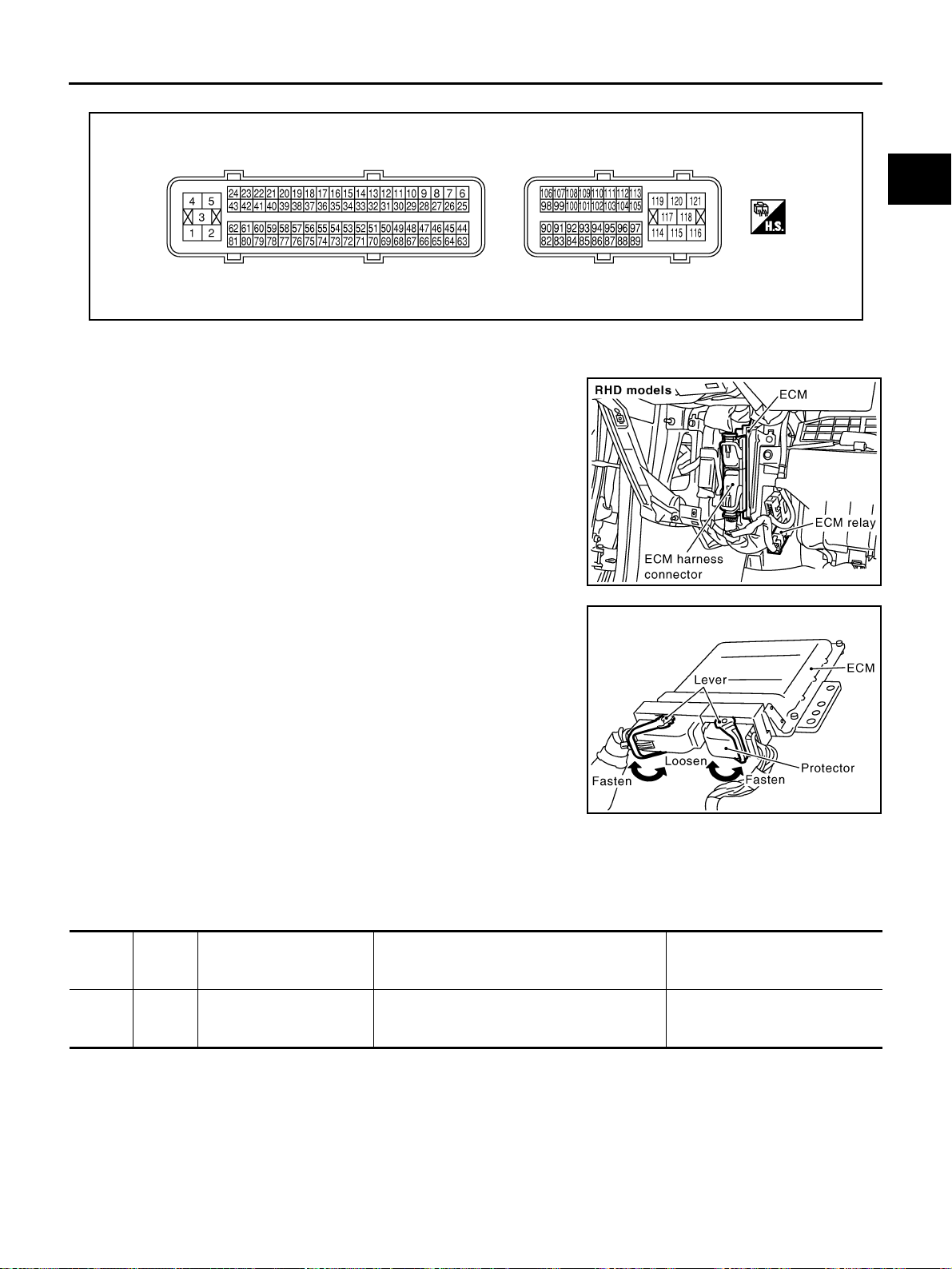
ECM Harness Connector Terminal Layout EBS0117E
ECM Terminals And Reference Value EBS0117F
PREPARATION
1. ECM is located behind the glove box. For this inspection,
remove glove box.
2. Remove ECM harness protector.
3. When disconnecting ECM harness connector, loosen it with
levers as far as they will go as shown in the figure.
4. Connect a break-out box (SST) and Y-cable adapter (SST)
between the ECM and ECM harness connector.
● Use extreme care not to touch 2 pins at one time.
● Data is for comparison and may not be exact.
ECM INSPECTION TABLE
Remarks: Specification data are reference values and are measured between each terminal and ground.
CAUTION:
Do not use ECM ground terminals when measuring input/output voltage. Doing so may result in dam-
age to the ECM's transistor. Use a ground other than ECM terminals, such as the ground.
MBIB0045E
PBIB1899E
PBIB1512E
TERMI-
NAL
NO.
WIRE
COLOR
ITEM CONDITION
DATA
(DC Voltage and Pulse Signal)
1
2
3
B
B
B
ECM ground
[Engine is running]
● Idle speed
Approximately 0V
Loading ...
Loading ...
Loading ...