Loading ...
Loading ...
Loading ...
DTC P0102, P0103 MAF SENSOR
EC-155
[QR (WITH EURO-OBD)]
C
D
E
F
G
H
I
J
K
L
M
A
EC
7. CHECK MAF SENSOR INPUT SIGNAL CIRCUIT FOR OPEN AND SHORT
1. Check harness continuity between MAF sensor terminal 4 and ECM terminal 50.
Refer to Wiring Diagram.
2. Also check harness for short to ground and short to power.
OK or NG
OK >> GO TO 8.
NG >> Repair open circuit or short to ground or short to power in harness or connectors.
8. CHECK MASS AIR FLOW SENSOR
Refer to EC-155, "
Component Inspection" .
OK or NG
OK >> GO TO 9.
NG >> Replace mass air flow sensor.
9. CHECK INTERMITTENT INCIDENT
Refer to EC-123, "
TROUBLE DIAGNOSIS FOR INTERMITTENT INCIDENT" .
>> INSPECTION END
Component Inspection EBS010N7
MASS AIR FLOW SENSOR
1. Reconnect harness connectors disconnected.
2. Start engine and warm it up to normal operating temperature.
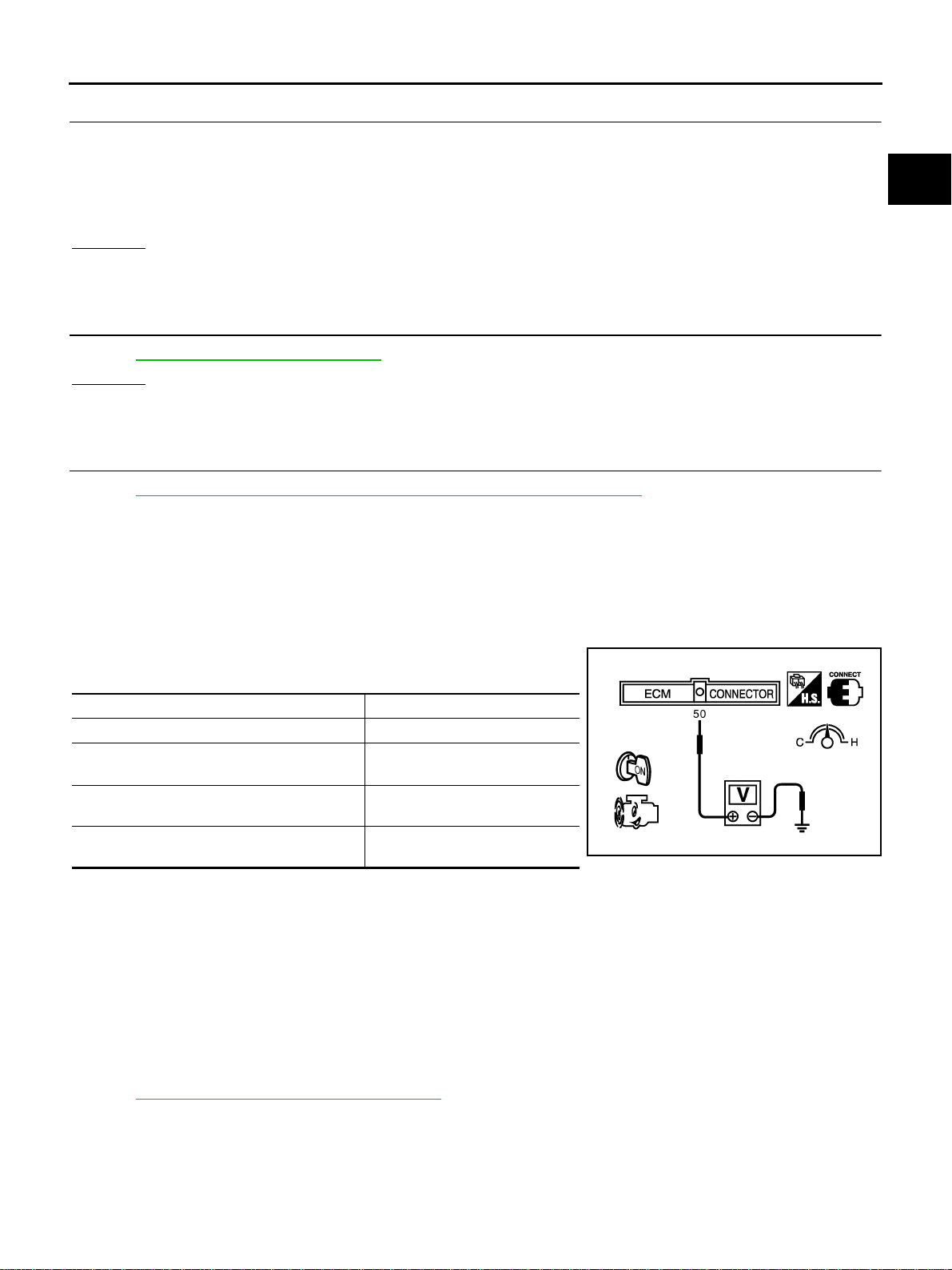
3. Check voltage between ECM terminal 50 (Mass air flow sensor
signal) and ground.
*: Check for linear voltage rise in response to engine being increased to about 4,000 rpm.
4. If the voltage is out of specification, proceed the following.
a. Turn ignition switch OFF.
b. Disconnect mass air flow sensor harness connector and reconnect it again.
c. Perform steps 2 and 3 again.
5. If NG, remove mass air flow sensor from air duct. Check hot wire for damage or dust.
6. If NG, clean or replace mass air flow sensor.
Removal and Installation EBS010N8
MASS AIR FLOW SENSOR
Refer to EM-15, "AIR CLEANER AND AIR DUCT" .
Continuity should exist.
Condition Voltage V
Ignition switch ON (Engine stopped.) Approx. 0.4
Idle (Engine is warmed-up to normal operating
temperature.)
0.7 - 1.1V (QR20DE)
0.8 - 1.2V (QR25DE)
2,500 rpm (Engine is warmed-up to normal
operating temperature.)
1.4 - 1.9V (QR20DE)
1.6 - 1.9V (QR25DE)
Idle to about 4,000 rpm*
0.7 - 1.1 to 2.4 (QR20DE)
0.8 - 1.2 to 2.4 (QR25DE)
MBIB0017E
Loading ...
Loading ...
Loading ...