Loading ...
Loading ...
Loading ...
EC-856
[QR (WITHOUT EURO-OBD)]
ELECTRICAL LOAD SIGNAL
Specification data are reference values and are measured between each terminal and ground.
CAUTION:
Do not use ECM ground terminals when measuring input/output voltage. Doing so may result in dam-
age to the ECM's transistor. Use a ground other than ECM terminals, such as the ground.
Diagnostic Procedure EBS01151
1. INSPECTION START
Do you have CONSULT-II?
Yes or No
Yes >> GO TO 2.
No >> GO TO 3.
2. CHECK LOAD SIGNAL CIRCUIT OVERALL FUNCITION-I
With CONSULT-II
1. Turn ignition switch ON.
2. Check “LOAD SIGNAL” in “DATA MONITOR” mode with CON-
SULT-II under the following conditions.
OK or NG
OK >> GO TO 4.
NG >> GO TO 8.
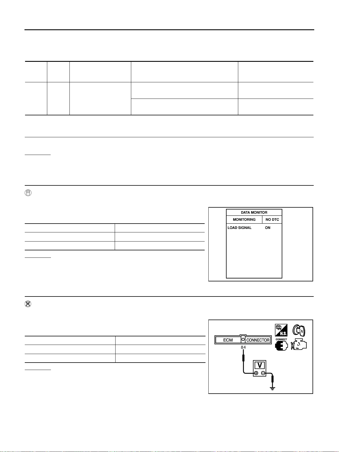
3. CHECK LOAD SIGNAL CIRCUIT OVERALL FUNCTION-I
Without CONSULT-II
1. Turn ignition switch ON.
2. Check voltage between ECM terminal 84 and ground under the
following conditions.
OK or NG
OK >> GO TO 5.
NG >> GO TO 8.
TERMI-
NAL
NO.
WIRE
COLOR
ITEM CONDITION DATA (DC Voltage)
93 BR
Electrical load signal
(Rear window defogger
signal)
[Ignition switch: ON]
● Rear window defogger switch: ON
BATTERY VOLTAGE
(11 - 14V)
[Ignition switch: ON]
● Rear window defogger switch: OFF
Approximately 0V
Condition LOAD SIGNAL
Lighting switch ON at 2nd position ON
Lighting switch OFF OFF
PBIB0103E
Condition Voltage
Lighting switch ON at 2nd position BATTERY VOLTAGE
Lighting switch OFF 0V
MBIB0158E
Loading ...
Loading ...
Loading ...