Loading ...
Loading ...
Loading ...
POWER SUPPLY AND GROUND CIRCUIT
EC-125
[QR (WITH EURO-OBD)]
C
D
E
F
G
H
I
J
K
L
M
A
EC
Specification data are reference values and are measured between each terminal and ground.
CAUTION:
Do not use ECM ground terminals when measuring input/output voltage. Doing so may result in dam-
age to the ECM's transistor. Use a ground other than ECM terminals, such as the ground.
Diagnostic Procedure EBS010M9
1. INSPECTION START
Start engine.
Is engine running?
Yes or No
Yes >> GO TO 11.
No >> GO TO 2.
2. CHECK ECM POWER SUPPLY CIRCUIT-I
1. Turn ignition switch OFF and then ON.
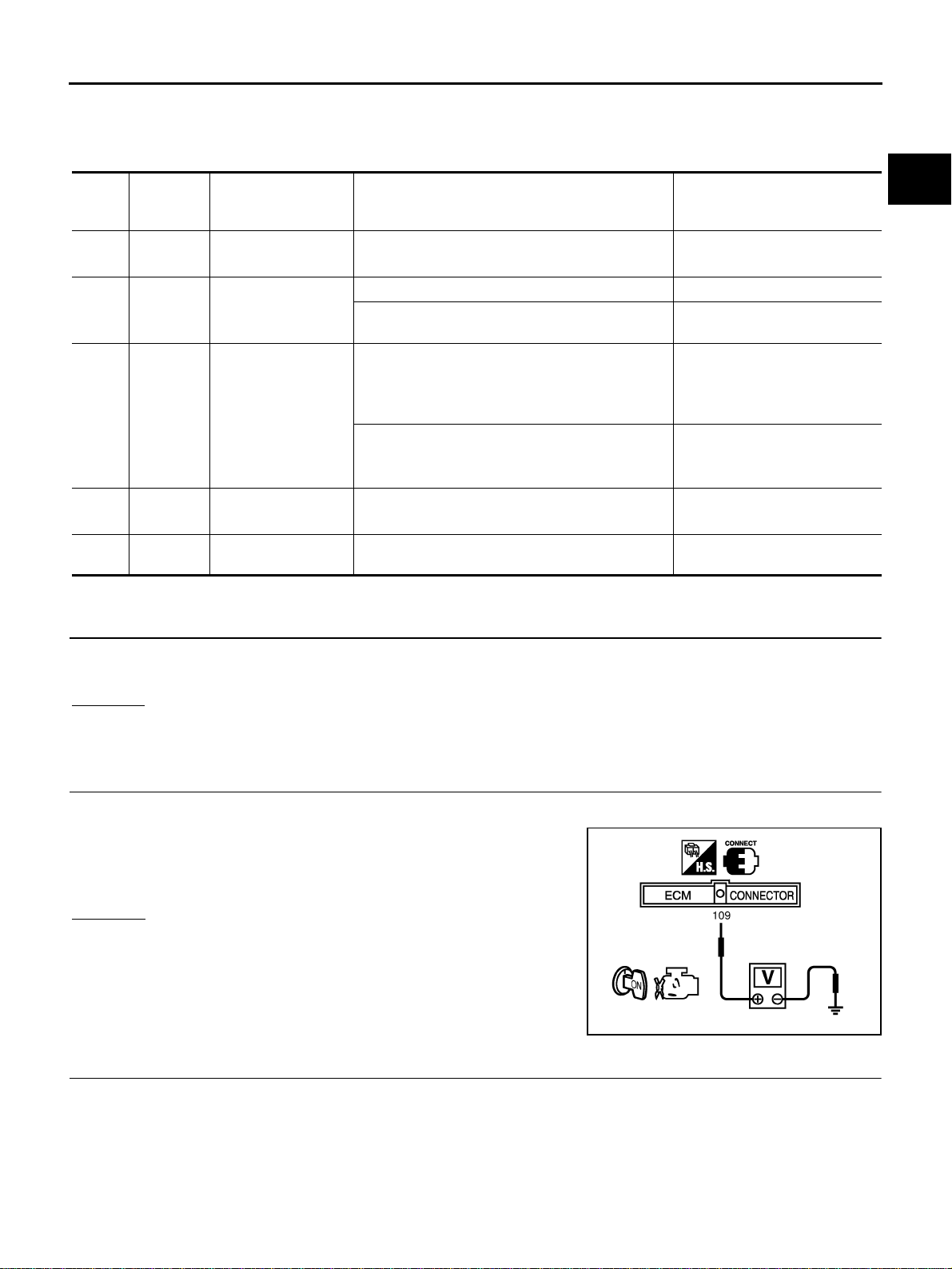
2. Check voltage between ECM terminal 109 and ground with
CONSULT-II or tester.
OK or NG
OK >> GO TO 4.
NG >> GO TO 3.
3. DETECT MALFUNCTIONING PART
Check the following.
● Fuse block (J/B) connector M1
● 10A fuse
● Harness for open or short between ECM and fuse
>> Repair open circuit or short to ground or short to power in harness or connectors.
TER-
MINAL
NO.
WIRE
COLOR
ITEM CONDITION DATA (DC Voltage)
1 B ECM ground
[Engine is running]
● Idle speed
Body ground
109 B/R Ignition switch
[Ignition switch: OFF] 0V
[Ignition switch: ON]
BATTERY VOLTAGE
(11 - 14V)
111 G/W
ECM relay
(Self shut-off)
[Engine is running]
[Ignition switch: OFF]
● For a few seconds after turning ignition switch
OFF
0 - 1.0V
[Ignition switch: OFF]
● More than a few seconds passed turning ignition
switch OFF
BATTERY VOLTAGE
(11 - 14V)
115
116
B
B
ECM ground
[Engine is running]
● Idle speed
Body ground
119
120
SB
GY
Power supply for
ECM
[Ignition switch: ON]
BATTERY VOLTAGE
(11 - 14V)
Voltage: Battery voltage
MBIB0015E
Loading ...
Loading ...
Loading ...