Loading ...
Loading ...
Loading ...
EC-818
[QR (WITHOUT EURO-OBD)]
PNP SWITCH
Specification data are reference values and are measured between each terminal and ground.
CAUTION:
Do not use ECM ground terminals when measuring input/output voltage. Doing so may result in dam-
age to the ECM's transistor. Use a ground other than ECM terminals, such as the ground.
Diagnostic Procedure EBS01AGU
1. CHECK OVERALL FUNCTION
With CONSULT-II
1. Turn ignition switch ON.
2. Select “P/N POSI SW” in “DATA MONITOR” mode with CON-
SULT-II.
3. Check the “P/N POSI SW” signal under the following conditions.
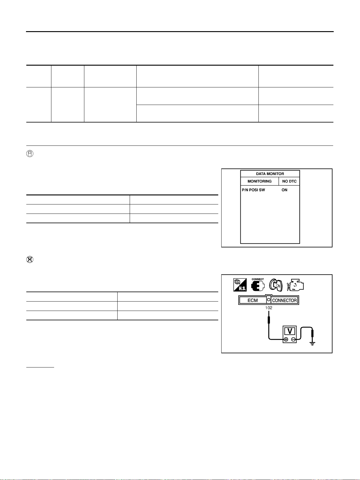
Without CONSULT-II
1. Turn ignition switch ON.
2. Check voltage between ECM terminal 102 and ground under the
following conditions.
OK or NG
OK >> INSPECTION END
NG >> GO TO 2.
TERMI-
NAL
NO.
WIRE
COLOR
ITEM CONDITION DATA (DC Voltage)
102 G/OR PNP switch
[Ignition switch: ON]
● Shift lever position: P or N
Approximately 0V
[Ignition switch: ON]
● Except above position
BATTERY VOLTAGE
(11 - 14V)
Selector lever position P/N POSI SW signal
P or N position ON
Except above position OFF
PBIB0102E
Selector lever position Voltage
P or N position Approximately 0V
Except above position Battery voltage
MBIB0043E
Loading ...
Loading ...
Loading ...