Loading ...
Loading ...
Loading ...
EC-464
[QR (WITH EURO-OBD)]
ELECTRICAL LOAD SIGNAL
Specification data are reference values and are measured between each terminal and ground.
CAUTION:
Do not use ECM ground terminals when measuring input/output voltage. Doing so may result in dam-
age to the ECM's transistor. Use a ground other than ECM terminals, such as the ground.
Diagnostic Procedure EBS010VU
1. INSPECTION START
Do you have CONSULT-II?
Yes or No
Yes >> GO TO 2.
No >> GO TO 3.
2. CHECK LOAD SIGNAL CIRCUIT OVERALL FUNCITION-I
With CONSULT-II
1. Turn ignition switch ON.
2. Check “LOAD SIGNAL” in “DATA MONITOR” mode with CON-
SULT-II under the following conditions.
OK or NG
OK >> GO TO 4.
NG >> GO TO 8.
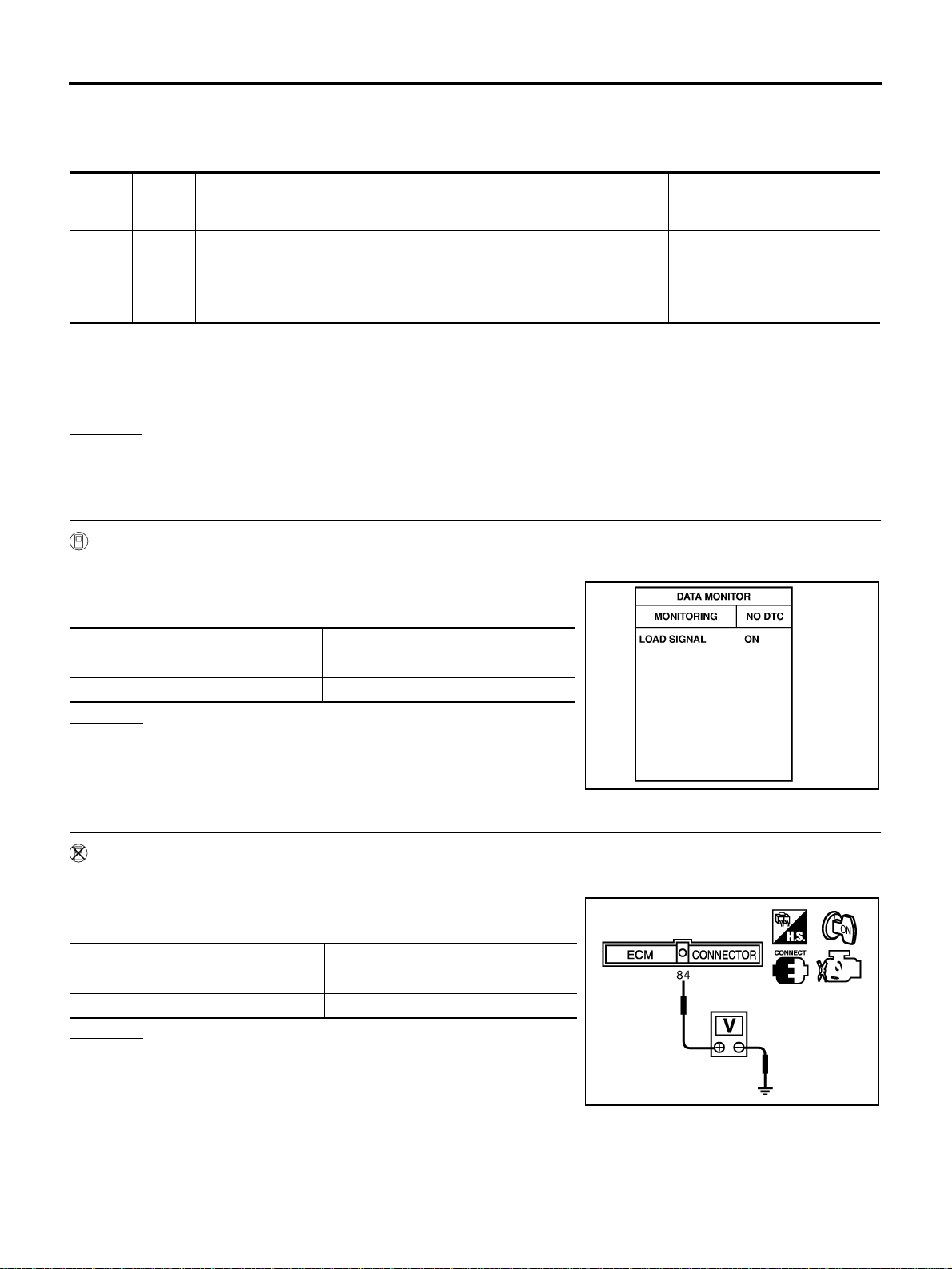
3. CHECK LOAD SIGNAL CIRCUIT OVERALL FUNCTION-I
Without CONSULT-II
1. Turn ignition switch ON.
2. Check voltage between ECM terminal 84 and ground under the
following conditions.
OK or NG
OK >> GO TO 5.
NG >> GO TO 8.
TERMI-
NAL
NO.
WIRE
COLOR
ITEM CONDITION DATA (DC Voltage)
93 BR
Electrical load signal
(Rear window defogger
signal)
[Ignition switch: ON]
● Rear window defogger switch: ON
BATTERY VOLTAGE
(11 - 14V)
[Ignition switch: ON]
● Rear window defogger switch: OFF
Approximately 0V
Condition LOAD SIGNAL
Lighting switch: ON at 2nd position ON
Lighting switch: OFF OFF
PBIB0103E
Condition Voltage
Lighting switch: ON at 2nd position BATTERY VOLTAGE
Lighting switch: OFF 0V
MBIB0158E
Loading ...
Loading ...
Loading ...