Loading ...
Loading ...
Loading ...
VDL (E3.1) 10/2020 Page 162/196
24.3 Object temperature display with flexible Pt 100 temperature sensor (option)
The object temperature display permits recording the object temperature directly on or in the drying mate-
rial. This enables the determination of the actual temperature of the charging material during the whole
process. The object temperature is measured via a flexible Pt100 sensor inside the inner chamber and can
be viewed on the controller display. The sensor needs to be in thermally conducting contact with the charg-
ing material. It can be plunged into humid charging material up to the length of its protecting tube.
The intrinsically safe connection cable is firmly connected (via an isolation amplifier) to the connection
“Object temperature input” (3a) located in the VDL rear connection panel. This cable connection is realized
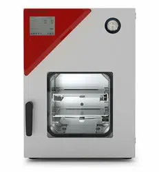
as a Lemo socket, which will be connected to a measuring access port on the measuring connection (12)
in the rear panel of the chamber.
24.3.1 Connection of the object temperature sensor
• Insert the Pt 100 temperature sensor from the rear through the measuring connection (12) into the inner
chamber.
• The 3 contacts of the Pt 100 sensor are conducted outside via a measuring access port. For reasons of
explosion protection, this electrical connection to the inner chamber is conducted via a triple internal
safety barrier with a conducting-state voltage of 1.6 Volt maximum against ground.
Technical data of the Pt 100 sensor:
• Three-wire technique
• Class B (DIN EN 60751)
• Temperature range up to 320 °C / 608 °F
• Stainless steel protective tube, length 45 mm / 1.77 in, stain-
less steel material no. 1.4501
Figure 29: Measuring connection (12) with measuring access
port
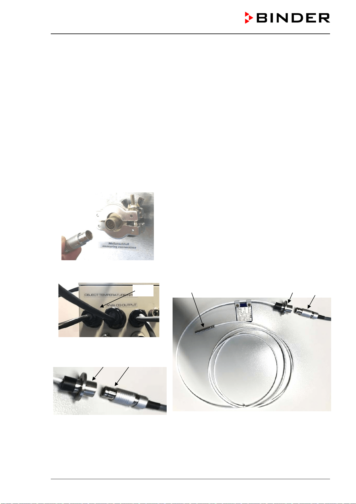
• Establish a plug connection between the measuring access port and the Lemo socket of the cable
,
w
hich is connected to the connection (3a)
(18) (16) (17)
F
igure 30: Connection cable on the “Object
temperature input” connection (3a)
(16) (17)
Figure 31: Plug connection between meas-
uring access port and Lemo socket
Figure 32: Cable connection of the optional Pt 100 sensor
(16) Measuring access port for Object temperature display
(17) Lemo socket
(18) Pt 100 Temperature sensor
(3a)
Loading ...
Loading ...
Loading ...