
Loading ...
Loading ...
Loading ...
PERIODIC MAINTENANCE 2-59
Periodic Maintenance Procedures
•
Turn the ignition switch off.
•
The all lights should go off.
For models equipped with an immobilizer system, red
warning indicator (LED) will blinks. Refer to the Immobi-
lizer System (Equipped Models) section in the Electrical
System chapter).
If the light does not go off, replace the ignition switch.
Second Step (Other than US, CA and CAL Models)
•
Turn the ignition switch to hazard position.
•
The all lights should go off.
If the light goes on, inspect or replace the following item.
Ignition Switch (see Switch Inspection in the Electrical
System chapter)
Third Step
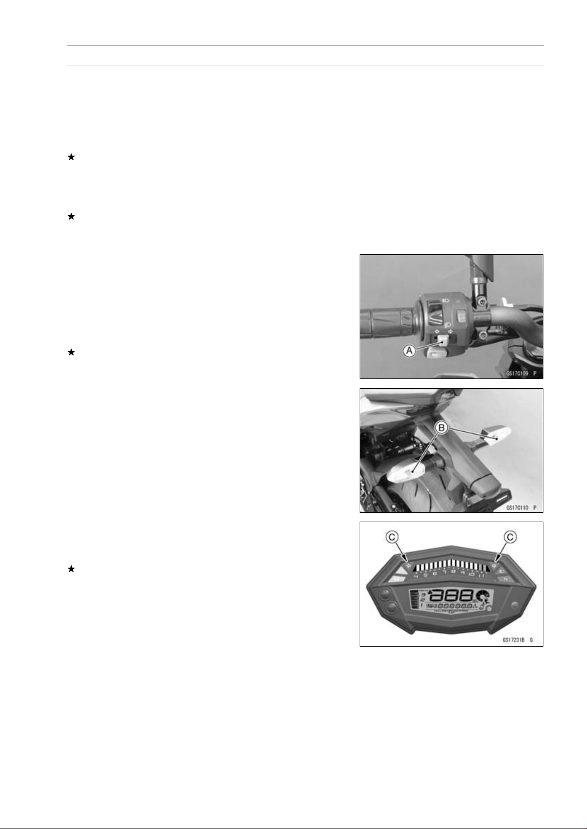
•
Turn the ignition switch on.
•
Turn on the turn signal switch [A] (left or right position).
•
The left or right turn signal lights [B] (front and rear) ac-
cording to the switch position should blink.
•
The green turn signal indicators (LED) [C] in the meter
unit should blink.
If the each light does not blink, inspect or replace the fol-
lowing parts.
Turn Signal Light Bulb (see Turn Signal Light Bulb Re-
placement in the Electrical System chapter)
Green Turn Signal Indicator (LED) (see Meter Unit In-
spection in the Electrical System chapter)
Turn Signal Relay Fuse 7.5 A (see Fuse Inspection in
the Electrical System chapter)
Turn Signal Switch (see Switch Inspection in the Electri-
cal System chapter)
Turn Signal Relay (see Turn Signal Relay Inspection in
the Electrical System chapter)
Harness (see Wiring Inspection in the Electrical System
chapter)
•
Push the turn signal switch.
•
The turn signal lights and green turn signal indicator (LED)
should go off.
If the light does not go off, inspect or replace the following
parts.
Turn Signal Switch (see Switch Inspection in the Electri-
cal System chapter)
Turn Signal Relay (see Turn Signal Relay Inspection in
the Electrical System chapter)
Loading ...
Loading ...
Loading ...