
Loading ...
Loading ...
Loading ...
FUEL SYSTEM (DFI) 3-125
Fuel Injectors
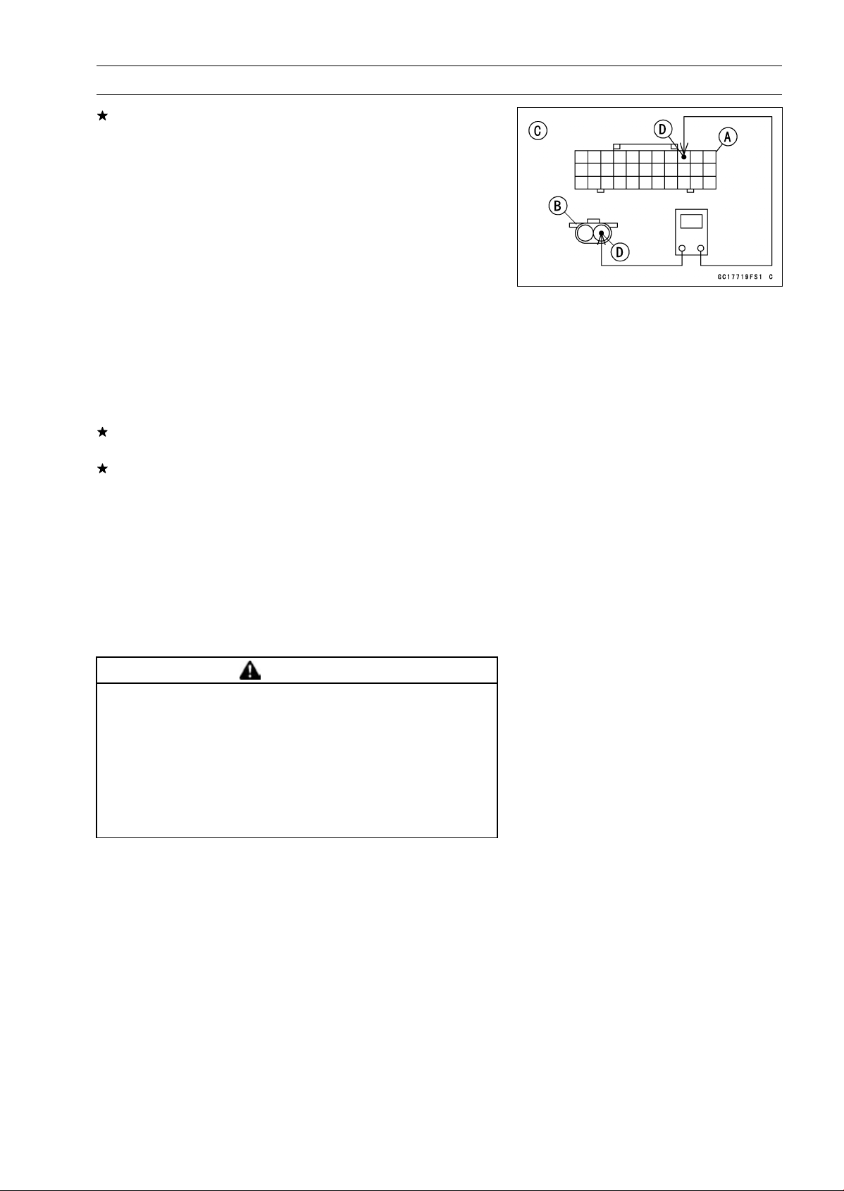
If the reading is out of the specification, remove the ECU
and check the wiring for continuity between main harness
connectors.
Disconnect the ECU and injector connector.
Wiring Continuity Inspection
ECU Connector (Gray)
[A]
←→
Fuel Injector Connector
[B]
For Fuel Injector #1 [C]
BL/BK lead (ECU terminal 42) [D]
For Fuel Injector #2
BL/R lead (ECU terminal 41)
For Fuel Injector #3
BL/O lead (ECU terminal 40)
For Fuel Injector #4
BL/G lead (ECU terminal 52)
If the wiring is good, check the ECU for its ground and
power supply (see ECU Power Supply Inspection).
If the ground and power supply are good, replace the ECU
(see ECU Removal/Installation).
Fuel Injector Fuel Line Inspection
•
Remove:
Fuel Tank (see Fuel Tank Removal)
Fuel Hose (see Fuel Hose Replacement in the Periodic
Maintenance chapter)
Be sure to place a piece of cloth around the fuel outlet
pipe of the fuel pump and the delivery pipe of the throttle
body assy.
WARNING
Fuel is flammable and explosive under certain con-
ditions and can cause severe burns. Be prepared
for fuel spillage; any spilled fuel must be completely
wiped up immediately. When the fuel hose is dis-
connected, fuel spills out from the hose and the
pipe because of residual pressure. Cover the hose
connection with a piece of clean cloth to prevent
fuel spillage.
Loading ...
Loading ...
Loading ...