
Loading ...
Loading ...
Loading ...
3-124 FUEL SYSTEM (DFI)
Fuel Injectors
Fuel Injector Output Voltage Inspection
NOTE
○
Be sure the battery is fully charged.
•
Turn the ignition switch off.
•
Remove the ECU (see ECU Removal).
Do not disconnect the ECU connector.
•
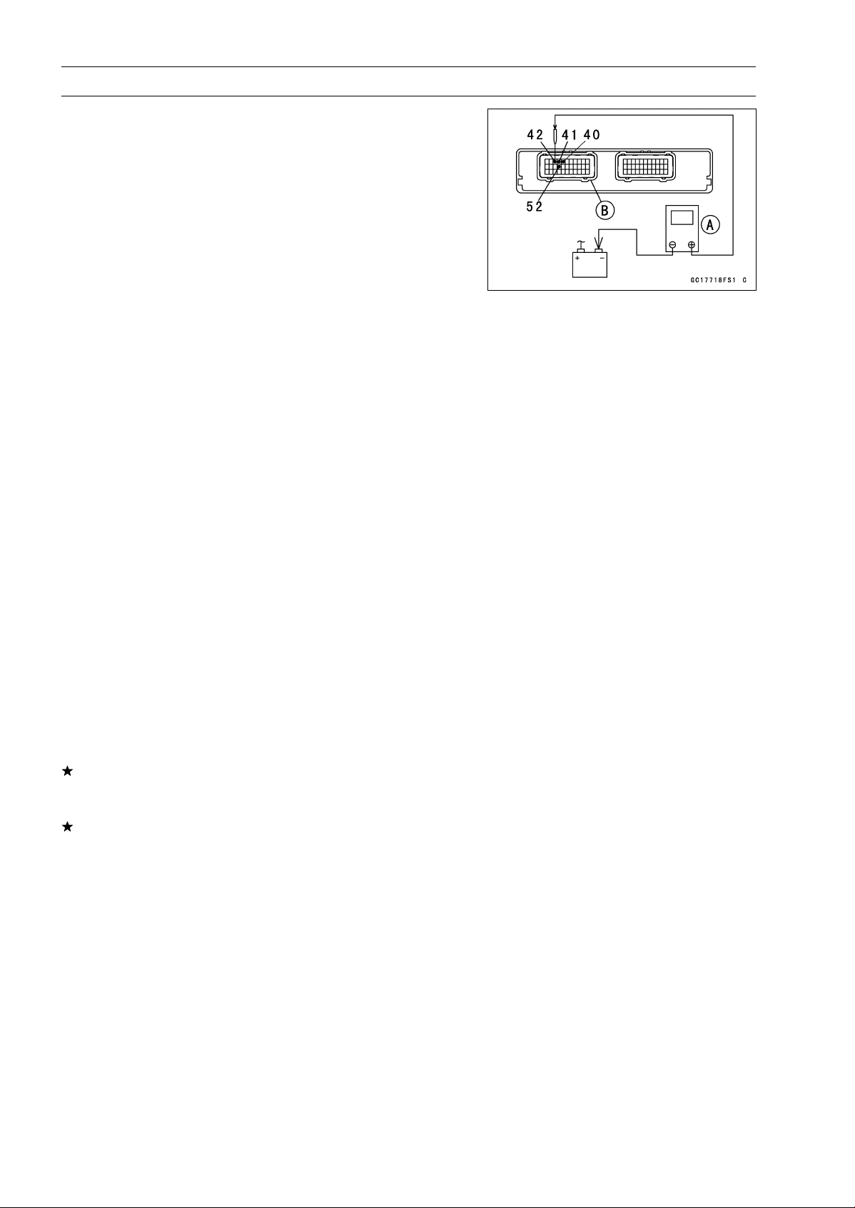
Connect a digital meter [A] to the connector [B] with the
needle adapter set.
Special Tool - Needle Adapter Set: 57001-1457
Fuel Injector Output Voltage
Connections to ECU Connector:
For Fuel Injector #1
Digital Meter (+) → BL/BKlead(ECUterminal42)
Digital Meter (–) → Battery (–) terminal
For Fuel Injector #2
Digital Meter (+) → BL/R lead (ECU terminal 41)
Digital Meter (–) → Battery (–) terminal
For Fuel Injector #3
Digital Meter (+) → BL/O lead (ECU terminal 40)
Digital Meter (–) → Battery (–) terminal
For Fuel Injector #4
Digital Meter (+) → BL/G lead (ECU terminal 52)
Digital Meter (–) → Battery (–) terminal
•
Measure the output voltage with the engine stopped and
with the connector joined.
•
Turn the engine stop switch to run position.
•
Turn the ignition switch on.
Output Voltage
Standard: Battery Voltage for 3 seconds, and then 0 V
•
Turn the ignition switch off.
If the reading is in specification, check the ECU for its
ground and power supply (see ECU Power Supply In-
spection).
If the ground and power supply are good, replace the ECU
(see ECU Removal/Installation).
Loading ...
Loading ...
Loading ...