
Loading ...
Loading ...
Loading ...
3-88 FUEL SYSTEM (DFI)
Immobilizer Amplifier (Service Code 35, Equipped Models)
Antenna Resistance Inspection
•
Turn the ignition switch off.
•
Remove the left middle fairing (see Middle Fairing Re-
moval in the Frame chapter).
•
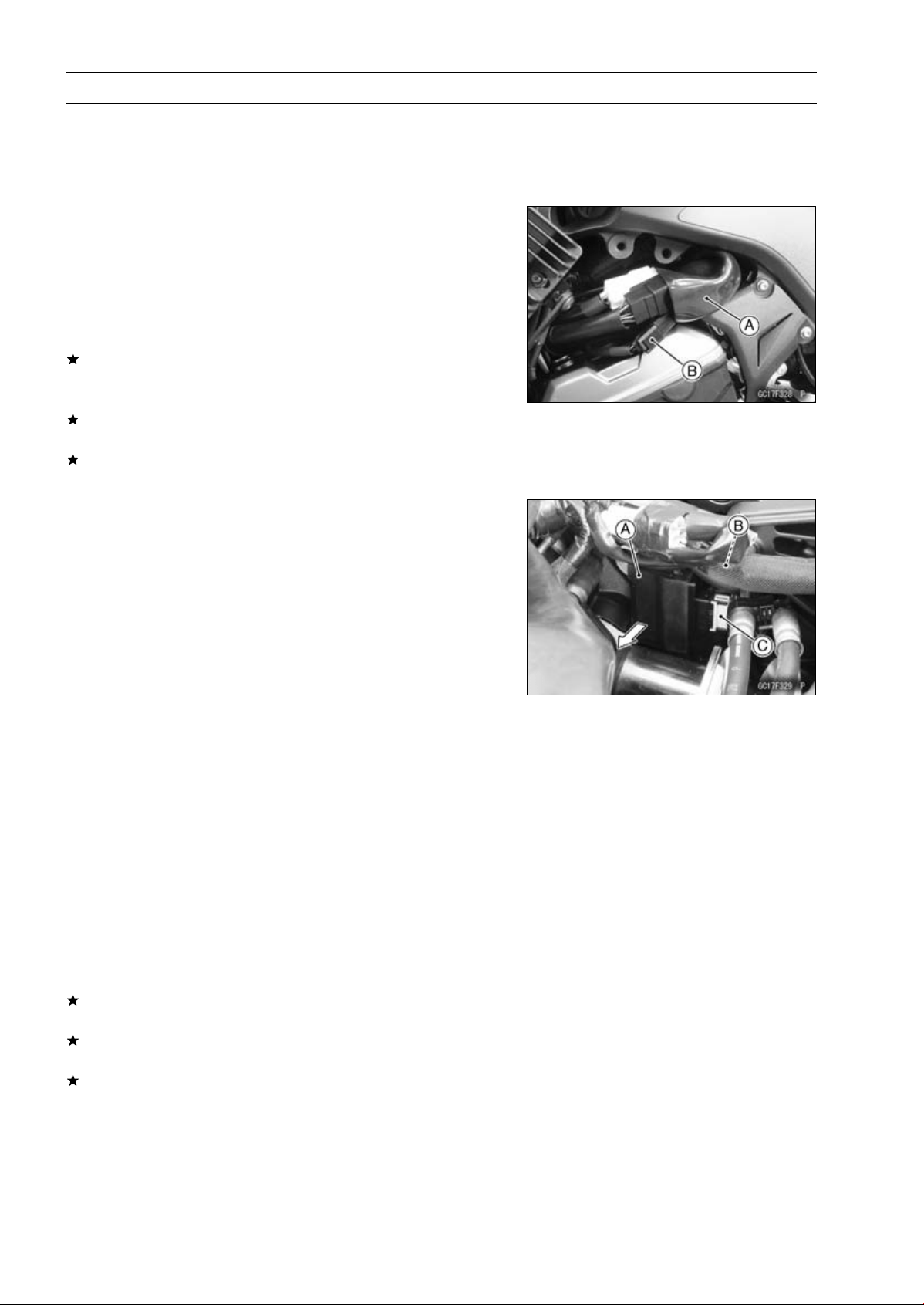
Slide the dust cover [A].
•
Disconnect the antenna lead connector [B].
•
Measure the antenna resistance.
Antenna Resistance
Connections: BK lead ←→ BK/W lead
Standard: About 3.0
∼ 4.6 Ω
If the reading is out of the standard, replace the ignition
switch (see Immobilizer System Parts Replacement in the
Electrical System chapter).
If the reading is within the standard, check the wiring to
the amplifier (see Immobilizer System Circuit).
If the wiring is good, check the input voltage of the ampli-
fier (see Amplifier Input Voltage Inspection).
Amplifier Input Voltage Inspection
NOTE
○
Be sure the battery is fully charged.
•
Turn the ignition switch off.
•
Remove the fuel tank (see Fuel Tank Removal).
•
Turn up the heat insulation rubber plate.
•
Pull out the immobilizer amplifier [A] from the bracket.
•
Open the clamp [B].
•
Connect a digital meter to the amplifier connector [C] with
needle adapter set.
Special Tool - Needle Adapter Set: 57001-1457
Amplifier Input Voltage
Connections to Amplifier Connector:
Digital Meter (+) → BR/W lead
Digital Meter (–) → BK/Y lead
•
Measure the input voltage with the engine stopped and
with the connector joined.
•
Turn the ignition switch on.
Input Voltage
Standard: Battery Voltage
•
Turn the ignition switch off.
If the reading is out of the standard, check the wiring (see
Immobilizer System Circuit).
If the reading is within the standard, check the wiring to
ECU (see Immobilizer System Circuit).
If the wiring is good, replace the amplifier (see Immobi-
lizer System Parts Replacement in the Electrical System
chapter).
Loading ...
Loading ...
Loading ...