Loading ...
Loading ...
Loading ...
16-72 ELECTRICAL SYSTEM
Meter, Gauge, Indicator Unit
Meter System Inspection
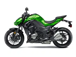
Check 2-1: Tachometer Brightness Sensor Inspection
NOTE
○
This meter unit has the automatically tachometer bright-
ness function by the sensor in addition to the manual
brightness setting.
•
Push the upper and lower buttons, and hold them in until
the all tachometer segments go on.
•
Check if the tachometer brightness [A] is changed by shin-
ing a light on the sensor [B] with the penlight.
•
Push the upper and lower buttons, and hold them to finish
the setting mode.
If the meter does not work, replace the meter unit.
Check 2-2: Water Temperature Inspection
•
Disconnect the water temperature sensor connector [A]
(see Water Temperature Sensor Removal/Installation in
the Fuel System (DFI) chapter).
•
Connect the variable rheostat [B] to the W/BL lead [C] and
W/R lead [D] terminals.
LCD Display Resistance (kΩ)
–––
1.231 or more
40°C (104°F)
1.136 ±0.095
100°C (212°F)
0.1553 ±0.0070
HI 0.1483 or less
•
Turn the ignition switch on.
•
Read the temperature in the display.
The display range is 40 ∼ 119°C (104 ∼ 247°F).
If the temperature is out of the range, check the wiring
(see Meter Circuit).
If the wiring is good, replace the meter unit.
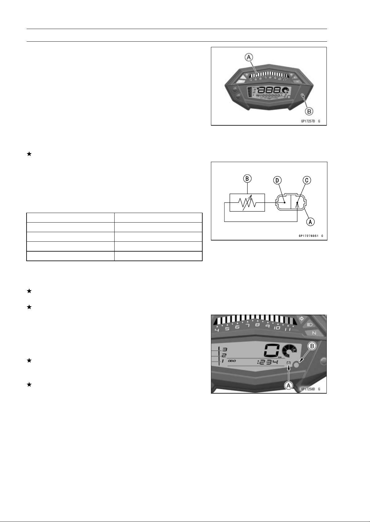
Check 2-3: Battery Warning Indicator Inspection
•
When the battery condition is low voltage (10.8 ∼ 11.2 V or
less) or high voltage (15.5 ∼ 16.5 V or more), the battery
warning indicator [A] and red warning indicator (LED) [B]
go on.
If the battery warning indicator and red warning indicator
(LED) go on, inspect the charging voltage (see Charging
Voltage Inspection).
If the charging voltage is good, replace the meter unit.
Loading ...
Loading ...
Loading ...