Loading ...
Loading ...
Loading ...
SQUARINGBLADETO FENCE
See Figures31A - 31C.
Thisproceduresquaresthe miterangleof the bladeto
the fenceto reducethe dskofbindingand kickback.If
the blade isnot squareto thefence, theyoke assem-
blymustbe rotatedslightly.Have a framing square,a
1/2 in.wrench, and a phillipsscrewdriverat hand.The
blade shouldbe loweredto justclear the table.
Release the carriage lockknob.
_k WARNING: The blademustbe angled at 90"to
the fence when the handle isat the frontof the
saw. If not,kickbackcould resultduringa cross
cut. Kickbackcan causeseriousinjuryby throw-
ingthe workpiecetowardtheoperator. In addi-
tion, a faulty miterangle on the bladecan splinter
or bum the cutedges ofthe workpiecedudng
cross cutsor dp cuts.
• Usethe arm lock knobto indexand lockthe arm in
0" miterposition(straightforward). .,
• Pullthe yoke assemblyforward tothe front ofthe
arm. Lockthe carriage lockknob.
• Placethe shortend ofthe framing squareagainst
the fence. Rotate thesquareto45°to thetable.
Placethe longedge acrosstheflat surfaceofthe
blade, belowthe center oftheblade. (Do notplace
theedge againsta tooth.)
• Check whetherthe blade isflat againsttheedge for
the entirelengthor whethera gap isvisible.
• Ifthe bladeneeds adjustment,removethe rightside
carriage coverwitha phillipsscrewddver.
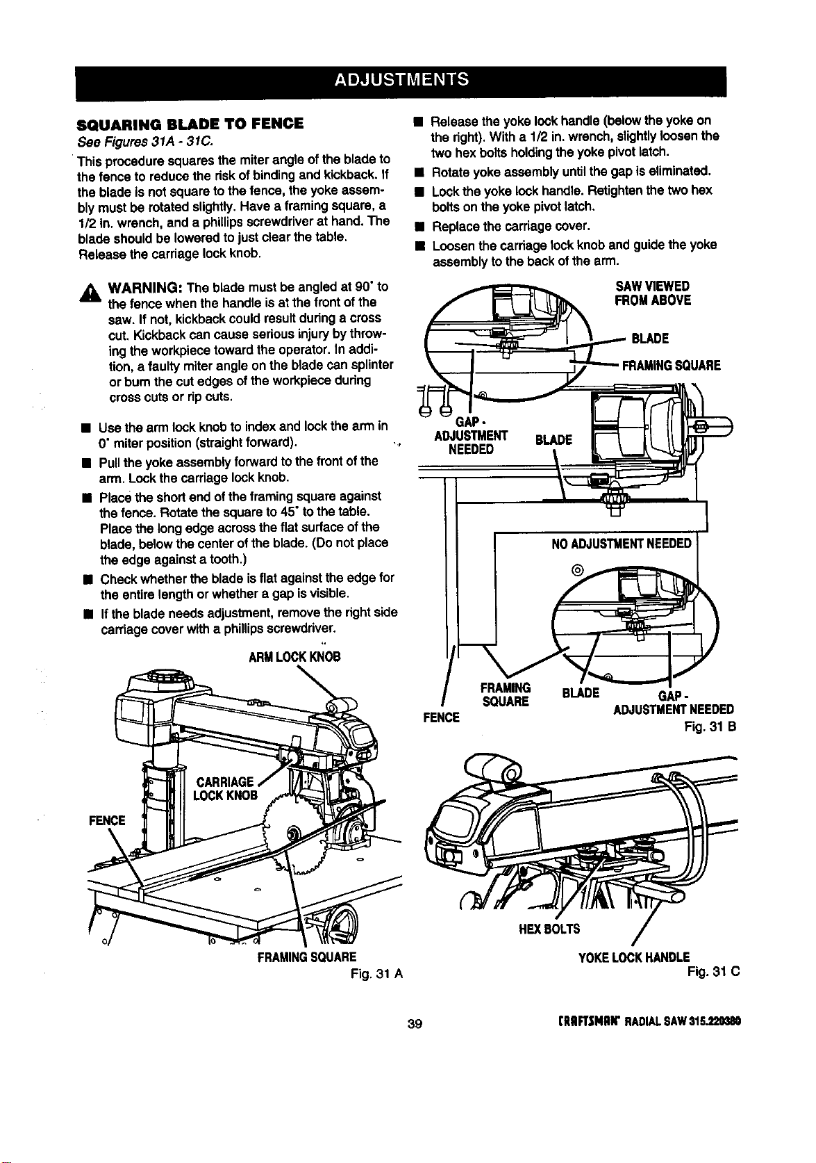
ARMLOCKKNOB
FENCE
FRAMINGSQUARE
Fig. 31 A
• Release theyoke lock handle(belowtheyoke on
the fight).With a 1/2 in.wrench,slightlyloosenthe
twohex boltsholdingtheyoke pivotlatch.
• Rotateyoke assembly untilthe gap iseliminated.
• Locktheyoke lockhandle.Retightenthetwo hex
boltson the yokepivotlatch.
• Replace thecarriagecover.
• Loosenthe carriagelockknoband guidethe yoke
assemblyto theback ofthe arm.
SAWVIEWED
FROMABOVE
BLADE
GAP-
ADJUSTMENT BLADE
NEEDED
I NOADJUSTMENTNEEDEDI
FRAMING BLADE GAP-
SQUARE
ADJUSTMENTNEEDED
FENCE
Fig. 31 B
HEXBOLTS
YOKELOCKHANDLE
Fig. 31 C
39 (RRFT|MRW RADIALSAW$1S_20380
Loading ...
Loading ...
Loading ...