Loading ...
Loading ...
Loading ...
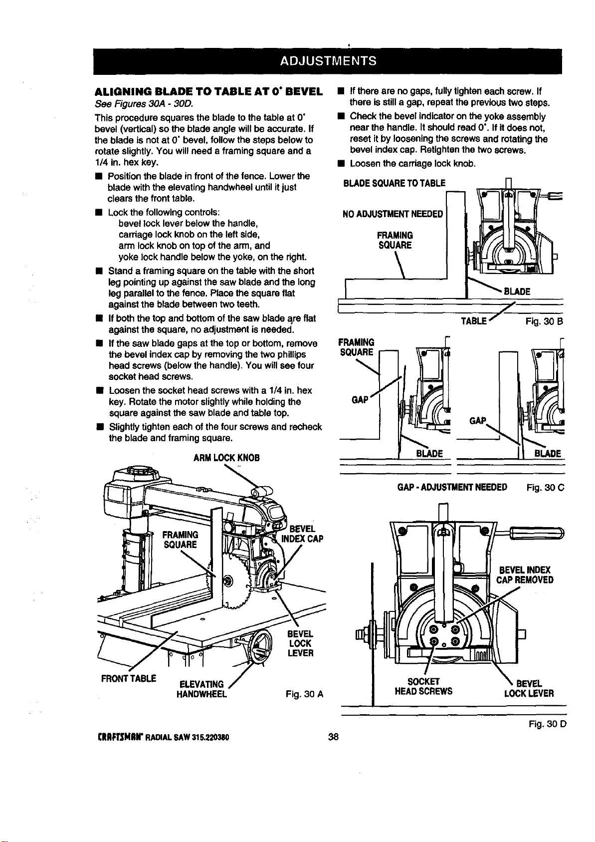
ALIGNING BLADE TO TABLE AT O" BEVEL
See Figures 30A - 30D.
This proceduresquaresthe blade tothe table at O"
bevel (vertical)sothe blade angle willbe accurate. If
the blade is not at D"bevel,followthe stepsbelowto
rotate slightly.You willneed a framing squareand a
1/4 in.hex key.
• Positiontheblade infrontofthefence. Lowerthe
bladewiththe elevatinghandwheeluntilitjust
clearsthe fronttable.
• Lockthe followingcontrols:
bevel locklever belowthe handle,
carriagelockknobon the leftside,
arm lock knobontop ofthe arm, and
yoke lockhandle belowtheyoke, on the dght.
• Stand a framing squareon thetable withthe short
leg pointingup againstthe saw bladeand the long
leg parallelto thefence. Place the squareflat
againstthe bladebetween two teeth.
• Ifboththe topand bottomofthe saw blade a_reflat
againstthe square, no adjustment isneeded.
• Ifthe saw bladegaps at the top or bottom,remove
thebevel indexcap by removingthe two phillips
head screws(belowthe handle).You willsee four
sockethead screws.
• Loosenthe sockethead screwswith a 1/4 in.hex
key. Rotate the motorslightlywhileholdingthe
square againstthe saw bladeand table top.
• Slightlytighteneachofthe fourscrews and recheck
the bladeand framing square.
ARMLOCKKNOB
• Ifthere are no gaps,fullytighteneach screw, If
there isstilla gap, repeatthe previoustwosteps.
• Checkthe bevel indicatoron the yokeassembly
near the handle.ItshouldreadO'. If itdoes not,
resetitby looseningthe screwsand rotatingthe
bevel indexcap. Retightenthe twoscrews.
• Loosenthecardagelockknob.
BLADESQUARETOTABLE
NO ADJUSTMENTNEEDED
FRAMING
SQUARE
FRAMING
SQUARE
BLADE
TABLEj Fig. 30 B
GAP
BLADE
FRONTTABLE
INDEXCAP
BEVEL
LOCK
LEVER
ELEVATING
HANDWHEEL Fig. 30 A
GAP-ADJUSTMENTNEEDED Fig. 30 C
SOCKET
HEADSCREWS
BEVELINDEX
CAPREMOVED
f
_.BEVEL
LOCKLEVER
Fig. 30 D
CRAFTSMIIH"RADIALSAW315.220380 38
Loading ...
Loading ...
Loading ...