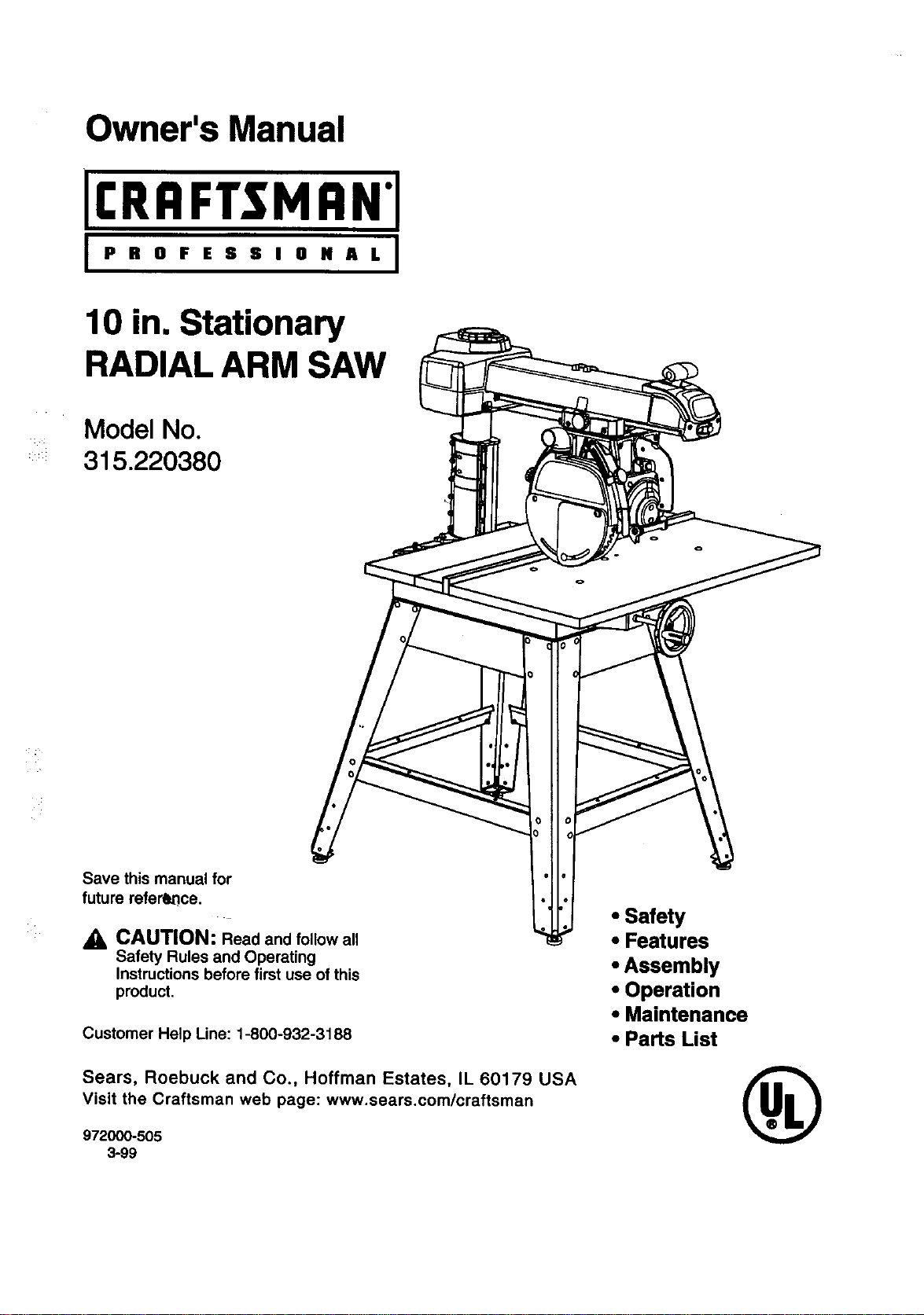
Owner's Manual
[I:RRFTSMRN'[
i PROFESSIONAL I
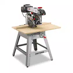
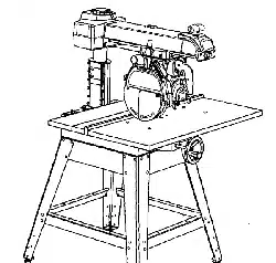
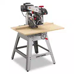
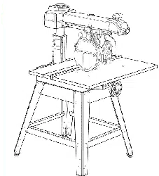
10 in. Stationary
RADIAL ARM SAW
Model No.
315.220380
Save this manual for
future reference.
CAUTION: Read and follow all
Safety Rules and Operating
Instructions before first use of this
product.
Customer Help Line: 1-800-932-3188
Sears, Roebuck and Co., Hoffman Estates, IL 60179 LISA
visit the Craftsman web page: www.sears.com/craftsman
972000-505
3-99
• Safety
• Features
• Assembly
• Operation
• Maintenance
• Parts List
®
FULL ONE YEAR WARRANTY ON CRAFTSMAN RADIAL ARM SAW
Ifthis CItRFTSMRN'Radial Arm Saw fails,dueto a defect inmaterialor workmanshipwithinone year fromthe
date of purchase, Sears willrepair it,free ofcharge.
Contacta Sears Service Center for repair.'
If thisproductisused for commercial'orrentalpurposes,this warrantyappliesonlyfor 90 daysfrom thedate of
purchase.
Thiswarranty givesyou specificlegal rights,and you may also have otherrightswhichvaryfrom state tostate.
Sears, Roebuck and Co., Dept. 817WA, Hoffman Estates, IL 60179
Yoursaw has many features for makingcuttingoperations more pleasantand enjoyable.Safety,performance
and dependabilityhave been giventop priorityin the design ofthissaw makingiteasy to maintainand operate.
_l, CAUTION: Carefullyread throughthisentireowner's manualbeforeusingyournew saw.Pay close
attentionto the RulesFor Safe Operation, and all Safety AlertSymbols,includingDanger,Warning and
Caution. Ifyou use yoursaw properlyand onlyfor what itis intended,you willenjoyyears ofsafe, reliable
service.
_k Look for this symbol to point out important safety precautions. It means attentionf!! Your safety is
involved.
,_ WARNING:
The operationof any powertoolcan resultinforeignobjectsbeing thrownintoyoureyes,
whichcan resultin severe eye damage. Before beginningpowertooloperation,always wear
safety gogglesor safety glasses withside shieldsand a full face shield when needed. We
recommendWide Vision Safety Mask for use over eyeglassesor standardsafety glasses
withside shields,available at Sears Retail Stores.
• Warranty and Introduction ............................................................................................................................... 2
• Table of Contents.......................................................................................................................................... 2-3
• Rules For Safe Operation............................................................................................................................. 4-7
• Electrical........................................................................................................................................................ 8-9
• ProductSpecificationsand Glossary........................................................................................................ 10-t 1
• Unpackingand Accessories.......................................................................................................................... 11
• Loose PartsList........................................................................................................................................ 12-14
• Tools Needed................................................................................................................................................. 15
• Labels........................................................................................................................................................ 16-17
• Features.................................................................................................................................................... 18-21
• Assembly................................................................................................................................................... 22-36
AssemblingLeg Stand ................................................................................................................................... 22
MountingSaw to Leg Stand........................................................................................................................... 23
I:RRFTSNRN"RADIALSAW315.220380 2
AttachingElevating Handwheel..................................................................................................................... 23
InstallingtheYoke Assembly......................................................................................................................... 24
Removingthe Blade....................................................................................................................................... 25
AttachingTable Supports.............................................................................................................................. 25
Settingthe Arm Lock Knob............................................................................................................................ 26
Settingthe Yoke Clamp ................................................................................................................................. 26
Settingthe Bevel LockLever......................................................................................................................... 27
Tighteningthe Armand Column.................................................................................................................... 28
Adjustingthe ColumnTube ...................................................................................................................... 28-29
Adjustingthe CarriageBearings.................................................................................................................... 30
Levelingthe Table Supports.......................................................................................................................... 31
Installingthe FrontTable ............................................................................................................................... 32
Levelingthe FrontTable ................................................................................................................................ 33
InstallingRear Table, SpacerTable, Fence, and Clamps........................................................................ 33-34
Installing Bladeand BladeGuard .................................................................................................................. 34
: AligningRivingKnifeto Blade........................................................................................................................ 35
InstallingRipScale Indicators........................................................................................................................ 36
• Adjustments................................................................ :;,............................................................................ 36-42
Aligningthe Armfor CrossCuts .................................................................................................................... 37
Aligningthe Bladeto Table at 0" Bevel ......................................................................................................... 38
SquadngBlade to Fence ............................................................................................................................... 39
ParallelingBladetoTable .............................................................................................................................. 40
Aligningthe Rip Scale Indicators ................................................................................................................... 41
InstallingControlCut Device ......................................................................................................................... 42
• Operation .................................................................................................................................................. 43-53
Basic Operationofthe Radial Arm Saw ........................................................................................................ 43
Types of Cuts ................................................................................................................................................. 43
Switchand Switch Key................................................................................................................................... 44
Causes ofK_ckback....................................................................................................................................... 44
. AvoidingKickback.......................................................................................................................................... 44
CuttingAids.................................................................................................................................................... 45
Making a CrossCut ....................................................................................................................................... 46
Making a Miter Cut......................................................................................................................................... 47
Makinga Bevel Cut........................................................................................................................................ 48
Making a CompoundCrossCut..................................................................................................................... 49
RipCut Hazards and Precautions................................................................................................................. 50
SettingUp a RipCut ................................................................................................................................. 50-51
Making a RipCut ........................................................................................................................................... 51
Making Other Cuts ......................................................................................................................................... 52
CuttingLongWorkpieces............................................................................................................................... 52
Non-ThroughCuts ......................................................................................................................................... 53
• Maintenance .................................................................................................................................................. 54
• Troubleshooting........................................................................................................................................ 55-59
• ExplodedView and Repair PartsUst ....................................................................................................... 60-81
• PartsOrdering/ Service .................................................................................................................... backpage
3 CRIIFTSHAN"RADIALSAW315.220380
The purpose of safety symbols is to attract your attention to possible dangers. The safety symbols, and
the explanations with them, deserve your careful attention and understanding. The safety warnings do
not by themselves eliminate any danger. The Instructions or warnings they give ere not substitutes for
proper accident prevention measures.
SYMBOL
A
A
&
Note:
MEANING
SAFETY ALERT SYMBOL
Indicatesdanger, warningor caution.May beused in conjunctionwithothersymbolsor
pictographs.
DANGER: Failuretoobey a safetywarningwillresultin seriousinjuryto yourselforto others.
Alwaysfollow thesafety precautionsto reducethe riskoffire, electricshockand personalinjury.
WARNING: Failureto obeya safety warningcan resultin serious injuryto yourselforto others.
Alwaysfollow thesafety precautionsto reducethe riskoffire, electricshockand personalinjury.
CAUTION: Failureto obeya safety warningmay resultin propertydamage or personalinjuryto
yourselfor toothers. Alwaysfollow the safety precautionsto reducethe riskoffire, electdcshock
and personalinjury.
Advisesyou of informationor instructionsvitaltothe operationor maintenanceofthe equipment.
IMPORTANT
Servicingrequiresextremecare and knowledgeofthe
systemand shouldbe performedonlybya qualified
service technician.For servicewe suggestyoucontact
your nearestSears repaircenter. Alwaysuse odginal
factory replacementpartswhen servicing.
If you havequestionsabouttermsinthe following
rules, refertothe GlossaryofTerms for Woodworking
or the Featuressection.
_l, WARNING: Do not attemptto operatethistool
untilyou have readthoroughlyand understand
completelyall instructions,safety rules,etc.
containedin thismanual. Failureto comply can
resultin accidentsinvolvingfire, electdcshock,
or sedous personal injury.Save owner'smanual
and review frequently for continuing safe
operation,and instructingotherswho may use
thistool.
READ ALL INSTRUCTIONS
KNOW YOUR POWER TOOL.Read the owner's
manualcarefully.Learnthe saw's applicationsand
limitationsas well as the specificpotentialhazards
relatedto thistool.
• DO NOT USE IN DANGEROUS ENVIRONMENT.
Do not use powertoolsnear gasolineor other
flammable liquids,in damp or wet locations,or
expose themto rain. Keep the work area well lit.
• KEEP CHILDREN AND VISITORS AWAY. All
visitorsshouldwear safety glasses and be kepta
safe distancefrom workarea. Do notlet visitors
contact the toolor extensioncordwhileoperating.
• KEEP WORK AREA CLEAN. Clutteredwork
areas and work benchesinviteaccidents. DO NOT
leave toolsor pieces ofwood on the sew while itis
in operation.Keep floorsclean and free of saw-
dust.
• MAINTAIN TOOLS WITH CARE. Keep toolssharp
and clean for better and safer performance. Follow
instructionsfor lubricatingand changingaccesso-
des.
• MAKE WORKSHOP CHILD-PROOF with padlocks
and masterswitchesor by removingswitchkeys.
• USE THE RIGHT TOOL FOR THE JOB. Do not
force thetoolor attachmentto do a job itwas not
designedfor. Use it onlythe way itwas intended.
DRESS PROPERLY, Do notwear looseclothing,
gloves, neckties,rings,bracelets, or otherjewelry.
They can getcaught and draw you intomoving
pads. Nonslipfootwearisrecommended.Also
wear protectivehaircovedngto containlonghair.
ALWAYS WEAR SAFETY GLASSES WITH SIDE
SHIELDS. Everyday eyeglasseshave onlyimpact-
resistantlenses;they are NOT safety glasses.
• NEVER STAND ON TOOL. Sedous injurycould
occur ifthe toolistipped or ifthe bladeis uninten-
tionallycontacted.
• DO NOT OVERREACH. Keep properfootingand
balanceat all times.
• SECURE WORK. Useclamps or a viseto hold
workwhen practical.It's saferthan usingyour
handand frees bothhandsto operatethe tool.
I]IIIFTSHIIN"RADIAL SAW 315.220380 4
n USE THE PROPER EXTENSION CORD. Make
sureyour extensioncordisin good condition,Use
onlya cord heavyenoughto carrythe currentyour
productwilldraw.An undersizedcordwillcause a
dropin linevoltage resultingin loss ofpowerand
overheating.A wiregage size (A.W.G.) of at least
14 is recommendedfor an extensioncord25 feet
or lessin length.If in doubt,use the nextheavier
gage. The smallerthe gage number,the heavier
thecord.
M AVOID ACCIDENTAL STARTING. Be sure switch
is offwhen pluggingin the tool.
• REMOVE WRENCHES AND ADJUSTING KEYS.
Get in the habitof checking- beforeturningon the
tool- thathex keys and adjustingwrenchesare
removedfrom tool.
DISCONNECT ALL TOOLS. When not in use,
beforeservicing,orwhen changingattachments,
blades, bits,cutters,etc., all toolsshouldbe
disconnectedfrom the power supply.
• DO NOT FORCE THE TOOL. It willdo thejob
better and more safelyat the rate for whichit was
designed.
• BEFORE MOUNTING, DISCONNECTING OR
REMOUNTING THE MOTOR; unplugthe saw and
removethe switchkey.
_IL WARNING: When servicing,use onlyidentical
Craftsmanreplacementparts.Use of anyother
partsmay create a hazard or damage product.
• CHECK DAMAGED PARTS. Beforeusingthe tool
again, check any damaged parts,includingguards,
for properoperationand performance.Check •
alignmentof movingparts,bindingof movingparts,,
breakage of parts, saw stability,mounting,and any
other conditions thatmay affect itsoperation.A
damaged part mustbe propedyrepairedor re- •
placed bya qualifiedservicetechnicianat a Sears
repaircenter to avoidriskof personalinjury.
USE ONLY CORRECT BLADES. Use the right
blade stylefor thematerial and the type of cut.
Use onlyblades markedfor at least5,000 rpmand
10 in. or smaller,with e 5/8 in.arbor hole.
• KEEP GUARDS IN PLACE and Ingood working
order.This includesthe blade guard,the dving
knife, and the anti-kickback pawls.
• CHECK DIRECTION OF FEED. When dpping,
feed work into a bladeor cutteragainstthe direc-
tionof rotation ofthe bladeor cutter.
• NEVER LEAVE TOOL RUNNING UNAI"rENDED.
TURN THE POWER OFF. Do not leavethe tool
untilitcomes to a completestop.
• USE RECOMMENDED ACCESSORIES. Using
improperaccessories may riskinjury.Consultthe
Accessoriessection for recommendedaccesso-
des.
M USE ONLY SEARS REPLACEMENT PARTS. All
repairs,whether electricalor mechanical,should
be made bya qualifiedservicetechnicianat a
Sears repaircenter.
NEVER USE THIS TOOL IN AN EXPLOSIVE
ATMOSPHERE. Normal sparkingofthe motor
could ignitefumes.
MAKE SURE THE WORK AREA HAS AMPLE
LIGHTING to see the workand that no obstruc-
tionswillinterferewithsafe operation BEFORE
performingany work usingthis tool.
DO NOT USE TOOL IF SWITCH DOES NOT
TURN IT ON AND OFF. Have defective switches
replaced bya qualified servicetechnicianat a
Sears repaircenter.
• GUARD AGAINST ELECTRICAL SHOCK by
preventingbodycontactwith groundedsurfaces
suchas pipes,radiators,ranges, refrigerator
enclosures.
M GROUND ALL TOOLS. See Electricalpage.
• WEAR A DUST MASK to keep frominhalingfine
particles.Use wooddustcollectionsystems
wheneverpossible.
m PROTECT YOUR HEARING. Wear headng
protectionduringextended periodsofoperation.
• DO NOT OPERATE THIS TOOL WHILE UNDER
THE INFLUENCE OF DRUGS, ALCOHOL, OR
ANY MEDICATION.
STAY ALERT AND EXERCISE CONTROL. Watch
what youare doingand use commonsense. Do
not operate tool when you are fired. Do not
rush.
AVOID AWKWARD OPERATIONS AND HAND
POSITIONS where a sudden slipcould cause your
handto move intothe blade. ALWAYS make sure
you havegood balance.
5 CRRFTSNRrRADfALSAW315._80
• GUARD AGAINST KICKBACK, Kickbackcan
occurwhen the bladestalls,drivingthe work piece
backtoward theoperator. It can causeyourhand
tocontact theblade, resultingin seriouspersonal
injury.Stay outof the blade pathand turnswitch
offimmediatelyit bladebinds or stalls.
• DO NOT USE A PERSON AS A SUBSTITUTE
FOR A TABLE ifadditional supportisneeded. Use
a supportthe same heightas thetable.
• USE A SUPPORT FOR THE SIDES AND BACK
OF THE SAW TABLE when sawingwide or long
workpiecesto minimizethe riskofblade pinching
and kickback.Use a sturdy"outrigger" supportto
preventtippingif a table extensionmore than24
incheslongis attached tothe saw.
• CUT ONLY WOOD, PLASTIC OR WOOD-LIKE
MATERIALS. Do notcut metal•
• BEFORE MAKING A CUT, be sure all adjustments
are secure.
I NEVER cut more than one piece at a tnme.DO
NOT STACK more than one workpieceon the saw
table at a time.
l DO NOT REMOVE THE SAW'S BLADE GUARD.
Never operate the saw withthe bladeguard
removed. Make sure all guardsare operating
properlybeforeeach use.
• NEVER PERFORM ANY OPERATION FREE-
HAND. Always place the workpieceto becut on
the saw table and positionitfirmlyagainst the
fence as a backstop.
• USE THE RIP FENCE. Always use a fence or
straightedge guide when ripping.
• BE SURE THE BLADE PATH IS FREE OF
NAILS. Inspectfor and remove all nailsfrom
lumberbefore cutting.
• BE SURE THE BLADE CLEARS THE WORK-
PIECE. Never startthe saw withthe bladetouching
the stock.
• KEEP HANDS AWAY FROM CUTTING AREA.
Do not reach underneathwork or in blade cutting
path with yourhandsand fingers for any reason.
Always turnthe poweroffwhen cut iscomplete.
• USE A PUSHBLOCK OR PUSHSTICK in ripmode
for workpiecesso smallthat yourfingersgo under
the bladeguard. NEVER TOUCH BLADE or other
movingpartsduring use, for any reason.
l
ALLOW THE MOTOR TO COME UP TO FULL
SPEED beforestartinga cutto avoid bladebinding
or stalling.
ALWAYS PUSH THE WORKPIECE when ripping;
never pullittowardthe saw.
DO NOT FEED THE MATERIAL TOO QUICKLY.
Do notforce the workpieceagainsttheblade.
ALWAYS TURN OFF SAW before disconnecting
it, toavoidaccidentalstartingwhen reconnecting
to thepowersupply.NEVER leave the saw
unattendedwhile connectedto a powersource.
• BEFORE CHANGING THE SETUP, REMOVING
COVERS, GUARDS, OR BLADE; unplugthe saw
and removethe switchkey.
• KEEP TOOL DRY, CLEAN, AND FREE FROM
OIL AND GREASE. Always usea clean cloth
when cleaning. Never usebrake fluids,gasoline,
petroleum-basedproducts,or anysolventsto
clean tool.
• KEEP BLADES CLEAN, SHARP AND WITH
SUFFICIENT SET. Sharpbladesminimizestalling
and kickback•Keep bladesfree of rust,grease,
and pitch.
_i, WARNING: Blade coastsafterbeingturnedoff.
USE ONLY OUTDOOR EXTENSION CORDS.
Use onlyextensioncordswiththe marking"Ac-
ceptablefor use withoutdoorappliances; store
indoorswhile notin use,"Use extensioncordswith
an electricalratingnot lessthan thesaw's rating.
Alwaysdisconnectthe extensioncordfromthe
outletbeforedisconnectingthe productfromthe
extensioncord.
INSPECT TOOL CORDS AND EXTENSION
CORDS PERIODICALLY and, ifdamaged, have
repairedbya qualifiedservicetechnicianat a
Sears repaircenter. Stay constantly aware ofcord
locationand keep it wellaway fromthe moving
blade.
DO NOT ABUSE CORD. Never yankthecordto
disconnectitfrom receptacle.Keep the cordfrom
heat, oil, and sharpedges.
SAVE THESE INSTRUCTIONS. Refer to them
frequently and use to instruct other users. If you
loan someone this tool, loan them these instruc-
tionsalso.
SAVE THESEINSTRUCTIONS
IHF{'INAr RADIALSAW315.220380 6
M SECURE THE SAW. Firmlyboltthe saw tothe leg
stand to keepthe saw fromtipping,walking,or
sliding.
B DO NOT SET UP WORK WITH THE BLADE
SPINNING. Keep the saw poweroffuntilyou are
ready to use it.
M RIP ONLY WORKPIECES LONGER THAN THE
BLADE'S DIAMETER. Never ripa pieceof wood
that isshorterthan the diameterof the blade.
m NEVER LOWER AN UNLOCKED REVOLVING
CUI-rlNG TOOL. Alwayslock thecarriage lock
knobbefore loweringthe blade.
M SHUT OFF THE POWER TO FREE A JAMMED
GUARD. Press the switchoff beforeputtingyour
hands near the blade. Wait forthe bladeto stop,
then free the guard.
B LOCK THE SAW BEFORE MOVING IT. Secure
the radial armwith the arm lockknob. Secure the
carriage withthe carriage lockknob.
B POSITION THE WORKPIECE WITH THE FIN-
ISHED SIDE DOWN. If theanti-kickbackpawls
catchthe woodto stop kickback,they couldmar
thetop surface or cause splintering.
M POSITION THE WORKPIECE SO NO ONE MUST
STAND IN LINE WITH THE BLADE. Ifkickbackor
climboccurs, a helper,operator, or observerin the
sawblade path couldbe seriouslyinjured.
M POSITION THE CUT SO THE WASTE PART
FALLS OFF. Never use a lengthstopon the free
end ofthe workpiece. Never applyforceto thefree
end or holditwhilethe sawblade isrotating.
WARNING: In a ripcut, holdingthecut-offedge
behindthe blade can causethe cut edges to
pinch,riskingkickback.It couldcause the blade
toclimbover the frontedge ofthe woodand
contactyourhand.
n BEFORE STARTING EACH CUT, check thatno
play existsin the carriage. Be sure the arm, yoke
and bevel locksand clamps are tight.Verify the
blade, aUhandles, bladewashers, and bladenuts
are secure.
M BEFORE MAKING A CUT, test the upperand
lowerblade guardsfor free movement up and
down. Positionthe nose of theguard tojust clear
the workpiece.
M AVOID KICKBACK AND POSSIBLE INJURY by
preventingheeling,grabbing,and pinching.
• BEFORE CUTTING, positionand tightenthe blade
guard and anti-kickbackpawls.Test thepawls to
make sure theywould stop kickbackifitstarted.
Keep the pointssharp.
M KEEP THE SAW BLADE PATH CLEAR. Position
the saw toallow enoughroomon all sides so
neitherthe operatornora visitorstands in linewith
the sawblade.
M AVOID HEELING by adjustingthe saw bladeso it
exactlyparallelsthe fence duringrippingopera-
tions.
M AVOID GRABBING in ripmode by keepingthe
saw bladecorrectly adjusted and byfeeding the
work fromthe infeedside (oppositetheanti-
kickbackpawls).
B AVOID PINCHING by usinga rivingknife and
sharpsaw blade. Keep the work positionedfirmly
againstthefence.
B USE IN-RIP WHENEVER POSSIBLE by position-
ingthe work sothe blade isbetween (inside)the
columnand the motor.
m NEVER ADJUST GUARD, PAWLS, OR BLADE
WITHOUT DISCONNECTING THE POWER.
Alwaysturnoffthe switchand unplugthe cord
beforefreeing a jammed blade, tighteninga loose
blade, or repositioningthe guardor pawls.
,_ CAUTION: Do notturnthe motorswitchon and
off rapidly.This can loosenthe sawblade.
n NEVER CUT MORE THAN ONE PIECE OF
WOOD AT A TIME. The feed willbe unevenand
couldcause the bladeto pick up one or more
piecesand cause seriousinjury.
B TURN OFF SAW IF A STRANGE NOISE OR
HEAVY VIBRATION OCCURS. Immediatelyturn
offthe saw, locatethe source, and correct the
problembeforeusingthe saw further.
U POSITION THE CUT SO THE BLADE WILL NOT
EXTEND BEYOND THE EDGE OF THE TABLE.
i
KEEP THE GUARDS IN PLACE AND THE WORK
SURFACE CLEAR DURING A CUT. Small objects
or woodsliverscan ricochetfrom the blade intothe
fence and backtowardthe operator. Ifthe blade
loosensslivers, removethem witha stick, notyour
hand.
• IN A RIP CUT, DO NOT LET GO OF THE WORK-
PIECE UNTIL THE CUT IS COMPLETE. When the
workpiece isfedintothe blade, pushthe workpiece
all the way pastthe blade.
7 CRAFTSHQN'RADIALSAW315.220380
EXTENSION CORDS
Use only3-wire extensioncordsthat have3-prong
groundingplugsand 3-pole receptaclesthataccept
the tool'splug.When usinga powertoolat a consider-
able distancefrom the powersource, usean exten-
sioncord heavyenoughto carrythecurrent thatthe
toolwilldrew. An undersizedextensioncordwill
cause a drop in linevoltage, resultingin a lossof
power and causingthe motortooverheat. Use the
chart providedbelowto determinethe minimumwire
size requiredin an extensioncord. Only roundjack-
eted cordslistedby Underwriter'sLaboratories(UL)
shouldbe used.
Length of Extension Cord Wire Size (A.W.G.)
Up to25 feet 14
26-100 feet 12
When workingwith thetooloutdoors,use an exten-
sioncordthat isdesignedforoutside use. This is
indicatedbythe lettersWA on the cord'sjacket.
Before usingan extensioncord, inspectitfor Looseor
exposedwires and cutor worninsulation.
_1_ CAUTION: Keep the cordaway from the cutting
area and positionthe cordsothat itwillnot be
caught on lumber,tools,or otherobjectsdudng
cuttingoperations.
ELECTRICAL CONNECTION
Your Sears Craftsman Radial Arm Saw ispowered by
a precisionbuiltelectricmotor.It shouldbe connected
to a power supply that Is 120 volts, 60 Hz, AC only
(normal household current). Itshouldbeconnected
to a 240 volt power supplyonly If It has been reset
according to the Instructions in this manual.The
motorhas been set at thefactory for 120 volts;if itis
reconnectedto operate at 240 volts,the main power
cord plugand any receptaclemustbe replacedwith
devices rated for 240 volts.Thistoolwillnotoperate
on directcurrent(DC). A substantialvoltagedropwill
cause a lossof power and the motorwilloverheat. If
the saw does not operatewhen plugged intoan outlet,
doublecheckthe power supply.
SPEED AND WIRING
The no-load speed ofyoursaw isapproximately3,600
rpm. Thisspeed isnot constant.Forvoltage, the
wiringin a shopisas importantas the motor'shorse-
power rating.A line intendedonlyfor lightscannot
propedycarry a powertoolmotor.Wire that is heavy
enoughfor a shortdistancewillbe too lightfor a
greater distance. A linethatcan supportone power
tool may not be able tosupporttwoor three tools.
GROUNDINGINSTRUC_ONS
In theevent of a malfunctionor breakdown,grounding
providesa path ofleast resistancefor electriccurrent
toreducethe riskof electricshock.This toolis
equippedwithan electriccordhavingan equipment-
groundingconductorand a groundingplug.The plug
mustbe pluggedintoa matchingoutletthat ispropedy
installedand groundedin accordancewithall local
codes and ordinances.
Do not modifythe plugprovided.Ifit willnot fit the
outlet,have the properoutletinstalledbya qualified
electrician.Improperconnectionof theequipment-
groundingconductorcan resultina riskof electric
shock.The conductorwith insulationhavingan outer
surfacethat isgreen withor withoutyellowstripesis
the equipment-groundingconductor.If repairor
replacementofthe electriccordor plugis necessary,
do notconnectthe equipment-groundingconductorto
a liveterminal.
Check with a qualifiedelectricianor servicepersonnel
ifthe groundinginstructionsare notcompletely
understood,or if indoubt asto whetherthetool is
properlygrounded.
Repair or replacea damaged or worncordimmedi-
ately.
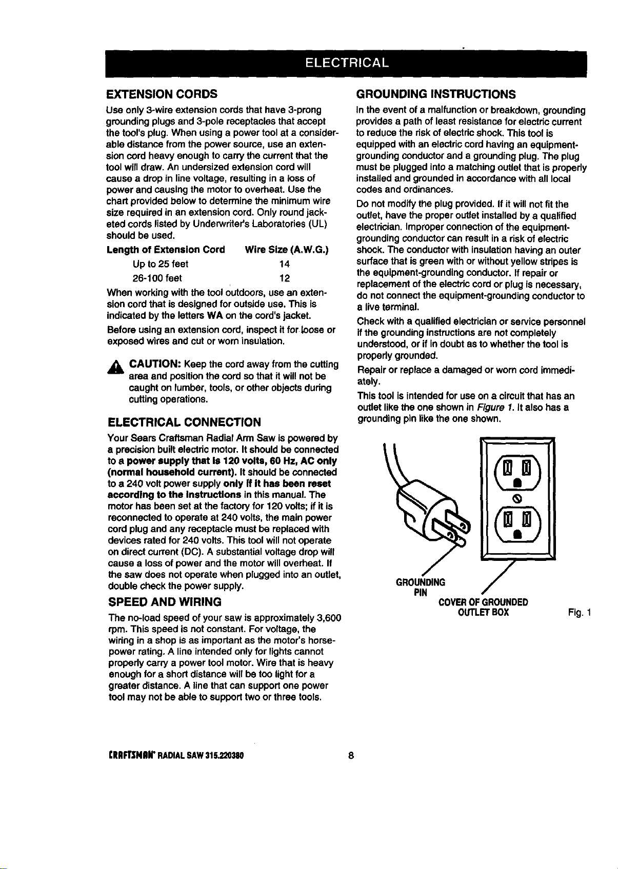
Thistool isintendedfor useon a circuitthat hasan
outletlikethe one shownin Figure I. Italso has a
groundingpinlikethe one shown.
1
PIN
COVEROFGROUNDED
OUTLETBOX
Fig. 1
CRAFTSMAN"RADIAL SAW 315,220380 8
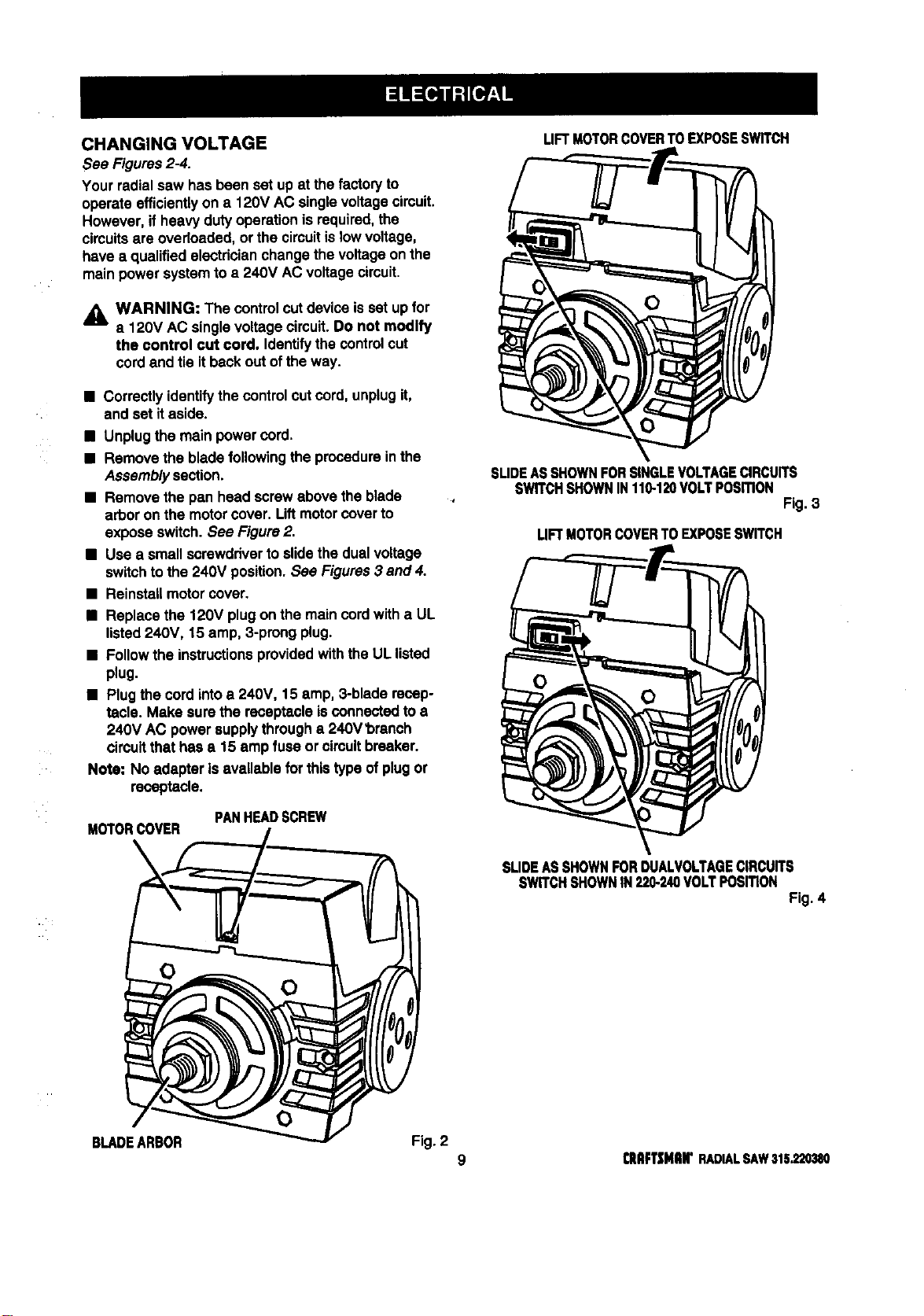
CHANGING VOLTAGE
See Figures2-4.
Your radial saw has been set up at the factoryto
operateefficientlyon a 120V AC singlevoltagecircuit.
However, if heavyduty operationisrequired,the
circuitsare overloaded,or the circuitis lowvoltage,
have a qualifiedelectdcianchangethe voltageonthe
main power systemtoa 240V AC voltagecircuit.
_l, WARNING: The controlcutdevice isset up for
a 120V AC singlevoltagecircuit.Do not modify
the control cut cord. Identifythe controlcut
cord and tie itbackout ofthe way.
• Correctlyidentifythe controlcutcord, unplugit,
and set itaside.
• Unplugthe main powercord.
• Remove the blade following the procedureinthe
Assemblysection.
• Remove the pan head screwabove theblade
arbor on the motorcover. Liftmotorcoverto
expose switch.See Figure2.
• Use a small screwdriverto slidethe dualvoltage
switchto the 240V position.See Figures3 and 4.
• Reinstallmotorcover.
• Replace the 120V plugon the main cordwith a UL
listed240V, 15 amp, 3-prongplug.
• Followthe instructionsprovidedwiththe UL listed
plug.
• Plugthe cordintoa 240V, 15 amp, 3-blade recep-
tacle. Make sure the receptacleisconnected to a
240V AC powersupplythrougha 240V'bmnch
circuitthat hasa 15 ampfuse orcircuitbreaker.
Note: No adapter isavailable for thistype of plugor
receptacle.
PANHEADSCREW
M_ORC_ER
LIFTMOTORCOVERTOEXPOSESWITCH
SUDEASSHOWNFORSINGLEVOLTAGECIRCUITS
SWITCHSHOWNIN110-120VOLTPosmoN
Fig. 3
LIFTMOTORCOVERTOEXPOSESWITCH
SLIDEASSHOWNFORDUN.VOLTAGECIRCUITS
SWITCHSHOWNIN220-240VOLTPOSmON
Fig. 4
0
BLADEARBOR Fig. 2
9 CnFT|NIIN"RADIALSAW315.220380
BladeArbor 5/8 in.
Blade Diameter 10 in.
Blade Bevel Angle 0"- 90"
Radial Arm Swing Range 50"left - 90" right
Blade Height Adjust 5.35 in.
Carriage Travel 17.25 in.
CuttingCapacity- MaximumCross Cut 15.50 in.
CuttingCapacity - MaximumOut-Rip 26 in.
CuttingCapacity- MaximumIn-Rip
Depth ofCut at 90"
Depthof Cut at 45"
Table Size
TableHeight
Rating
Input
No LoadSpeed
16 in.
3 in.
2.25 in.
40 x 27.75 x 1 in.
36 in.
120V/240V 60 Hz - AC only
13.0/6.5 Amperes
3,600 RPM
Bevel Cut
A cutmade acrossa workpiecewiththe blade at any
angle otherthan 90°to the table surface.
Chamfer
A cut removinga wedge froma blocksothe end (or
partof it) isangled ratherthan at 90 degrees.,
Climb
A hazard in whichthe blade=climbs" overand out of
theworkpiece, pullingthe stockout of the operator's
handsor runningacross theworkpiece.
Compound Cut
A crosscut withbotha miterangle and a bevel angle.
Cross Cut
A cuttingoperation withthe bladeparallelto the
carriage arm and the bladeteeth pointingdown. Itcan
be across or withthe grain, normallyacross the grain
or widthof the workpiece.
Dado Cut
A non-throughcutthat leavesa square notchor
trough;requiresa specialblade.
Featherboard
A deviceto help guideworkpiecesduringripcuts.
Fence
A piece of woodusedas a edge guidefor the
workplace.Locatedperpendiculartothe carriage arm.
Can be placed at differentdistancesfrom the rear
table edge in combinationwith theother table pieces
and issecured withtable clamps.
Freehand
Dangerouspracticeof makinga out withoutusinga
fence.
Gum
A sticky, sap-based residuefromwood products.
Heel
Alignmentofthe blade tothefence.
Infeed
The side ofthe blade where theblade teethpointup,
oppositethe anti-kickbackpawls.
In-Rip
A type of ripcut in whichthe blade isbetween the
columnand the motor.
Kerr
The space leftbythe removalofmaterialin a cutor
the slotproducedbythe blade ina non-throughcut.
Kickback
A hazard thatcan occurwhen blade bindsor stalls,
throwingworkpieceback towardoperator.
Leading End
The end ofthe workpiecepushedintothe cuttingtool
first.
Miter Cut
A verticalcutmade at anyangle otherthan 0" across
the workpiece.
Molding
A shapingcutthat gives a vaded shapeto the
workpieceand requiresa specialblade.
Out-Rip
Atype of ripcut inwhichthe motoris betweenthe
bladeand the column.(The blade is"outside"the
motor).
Pushatlck
A device usedto feed theworkpiecethroughthe saw
blade duringcuttingoperations.It helpskeepthe
operator'shandswell away fromthe blade.
Rabbet
A type ofcutthatgives a notchin the edge of a
workpiece.
Resaw
A cuttingoperationto reducethe thicknessofthe
workplaceto make thinnerpieces.
(IIRR'$NRIr RADIALSAW315.220380 10
Resin
A sticky,sap-based substance.
Rip Cut "
In a radial saw, a cutmade withthe bladeparallelto
the fence and perpendiculartothe arm. Can be
acrossor with thegrain.The teeth pointup at the
pointofcontactwith the wood,
Sawblade Path
The area directlyin line withthe blade-- over, under,
behind, or in frontof it. Also,the workpiecearea which
willbe or has been cutby theblade.
Set
The distance that the tip of the saw blade tooth is off
sat from the face of the blade.
Throw-Back
Saw throwingbacka workpiecesimilartokickback.
Through Sawing
AnyCuttingoperationwhere the bladeextends
completelythroughtheworkpieca.
Trailing End
The workpieceend lastcut bythe blade ina ripcut.
Workplace
The itemon whichthe cuttingoperationis beingdone.
The surfacesof a workpieceare commonly referredto
as faces, ends,and edges.
Worktable
The surfaceon whichtheworkpieca restswhile
performinga cuttingoperation.
,&
WARNING: To preventaccidentalstartingthat
could cause possibleseriouspersonalinjury,
assemble all partsto yoursaw beforeconnecting
itto powersupply.The saw shouldnever be
connected tothe powersupplywhen you are
assemblingparts,makingadjustments,installing
or removingblades, or when notin use.
_, WARNING: If any partsare missing,do not
operate thistool untilthe missingpartsare
replaced.Failure todo so couldresultin possible
seriouspersonalinjury.
• Carefullyremove all partsfrom thecarton and
place the saw on a levelworksurface. Separate
and checkagainstthe listoflooseparts.
• Do not discardthepackingmaterialsuntilyou have
carefullyinspectedthe saw, identifiedall parts,and
satisfactorilyoperated yournew saw.
Note: If any partsare damaged or missing,do not
attempttoplug inthe powercord and turnthe
switchon untilthe damaged or missingparts
are obtainedand are installedcorrectly.
The followingrecommendedaccessoriesare currentlyavailableat Sears RetailStores.
• Steel and carbide tippedcircularsaw blades • Adjustabletaper jig
• Hold down clamps • Sawdustcollectorshroud
• Saw baskets
WARNING: The use ofattachmentsor accessoriesnotlistedmightbe hazardous.
11 CRIIFTSNRN"RADIALSAW315.220380
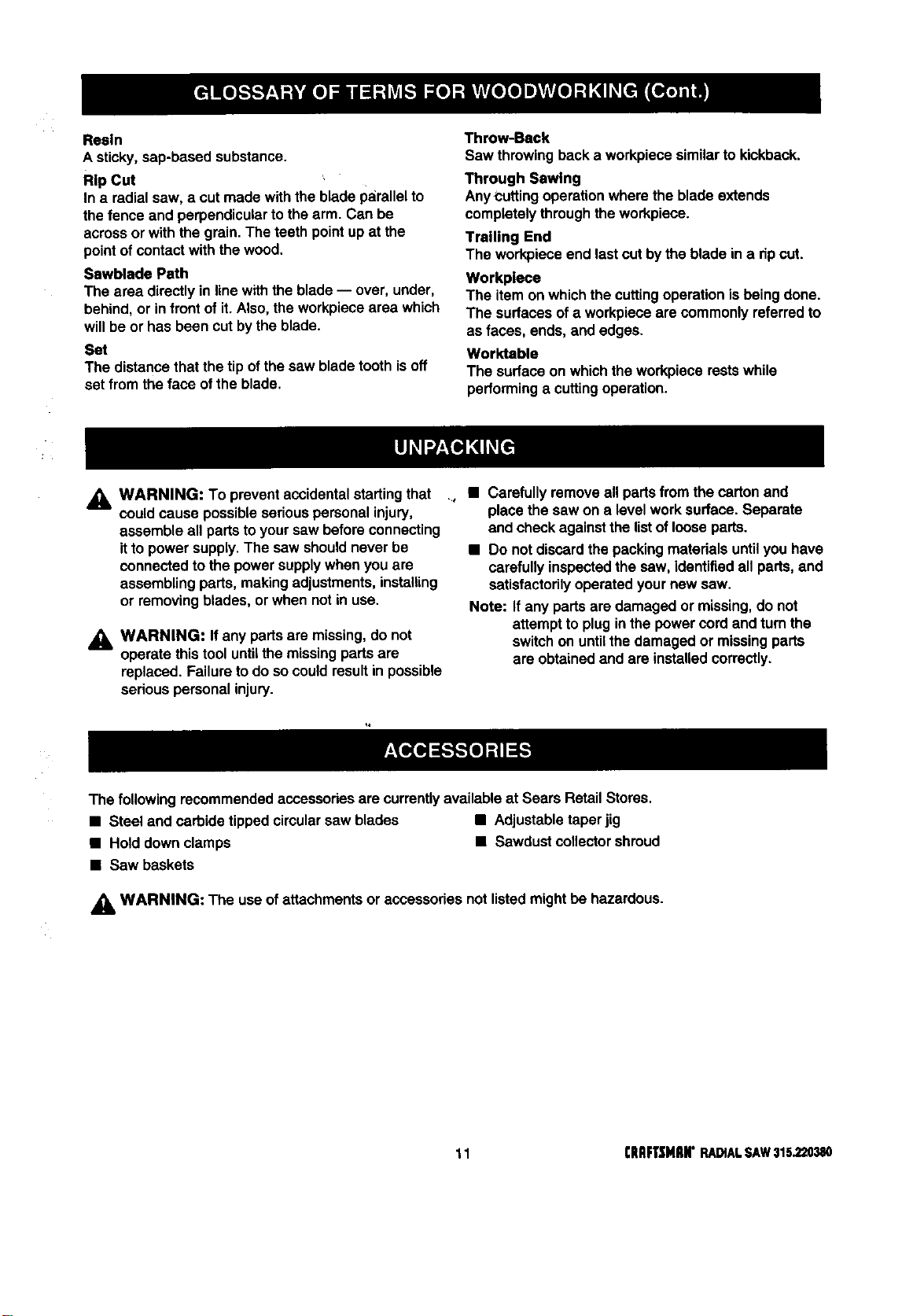
Checkall looseparts fromthe box withthe listbelow. Use the instructionson the followingpages to assemble.
Allfasteners are shownactual size.
f. Saw Assembly.................................................... 1
SAWASSEMBLYSHOWNASPACKED
21
ElevatingHandwheel
A. Handwheel................................................... ;. 1
B. Screw (10-24 x 5/8 In. Soc. Hd.).................... 1
C. StarWasher................................................... 1
c
(IUImMlUr RADIALSAWS15._,0_180
Fig. 5
3; BladeWrench..........;.......................................... 2
4. Hex Key
A. 3/16 In. Hex Key............................................. 1
B. 1/4 in.Hex Key............................................... 1
Fig.6A
12
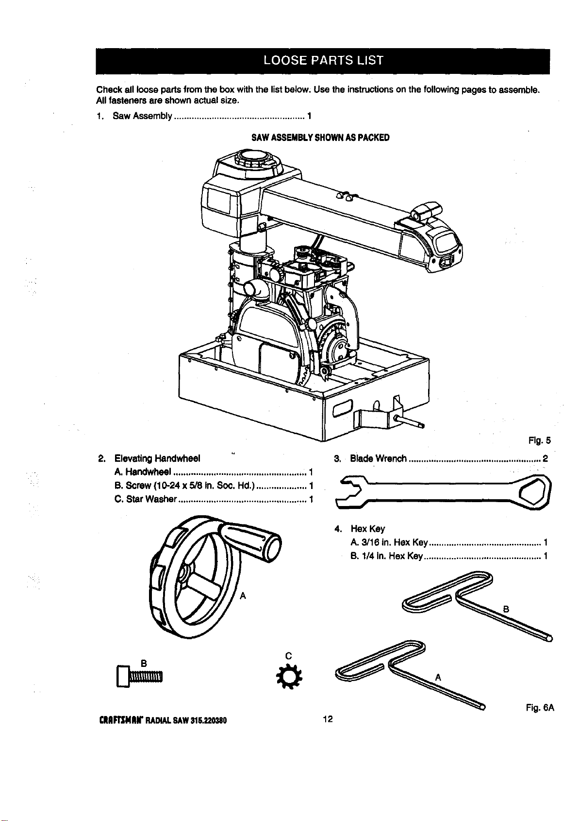
Checkall loosepartsfromthe box withthe listbelow. Use the Instructions on the followingpages to assemble.
Allfasteners are shownactual size.
5. Saw Base To Leg Stand Assembly
A. Saw Assembly(not shown) ........................... 1
B. Leg Stand Assembly(notshown).................. 1
C. Hex bolt (5/16-18 x 5/8 in.Hex Head) ........... 4
D. Washer (5/16 in.) ........................................... 8
E. Lockwasher (5/16 in.) ................................... 4
F. Hex Nut (5/16-18) ........................................... 4
C D E F
9. Fence.................................................................. 1
10. LevelingHardware for FrontTable
A. Screw(1/4-20 x 1-3/4 in.) .............................. 1
B. Washer........................................................... 1
C. U-clip.............................................................. 1
D. Setscrew........................................................ 1
6. Hardware for FrontTable
A. Fronttable ...................................................... 1
B. Screw (1/4-20 x 1 in.)..................................... 4,
C. Washer (1/4 in.) ............................................. 4
D. Lockwasher (1/4 in.) ..................................... 4
11. Scale Indicator
E. Tee nut........................................................... 1
A B
D E
A. Screw............................................................. 4
B. Speed Nut ...................................................... 2
C. Indicator......................................................... 2
D. SwitchKey..................................................... 2
7, RearT:ble .....................: .................: ................:.I
8. Spacer Table ...................................................... 1
Fig. 6B
13 CHFi2HIIN"RADIALSAWIlS.220UO
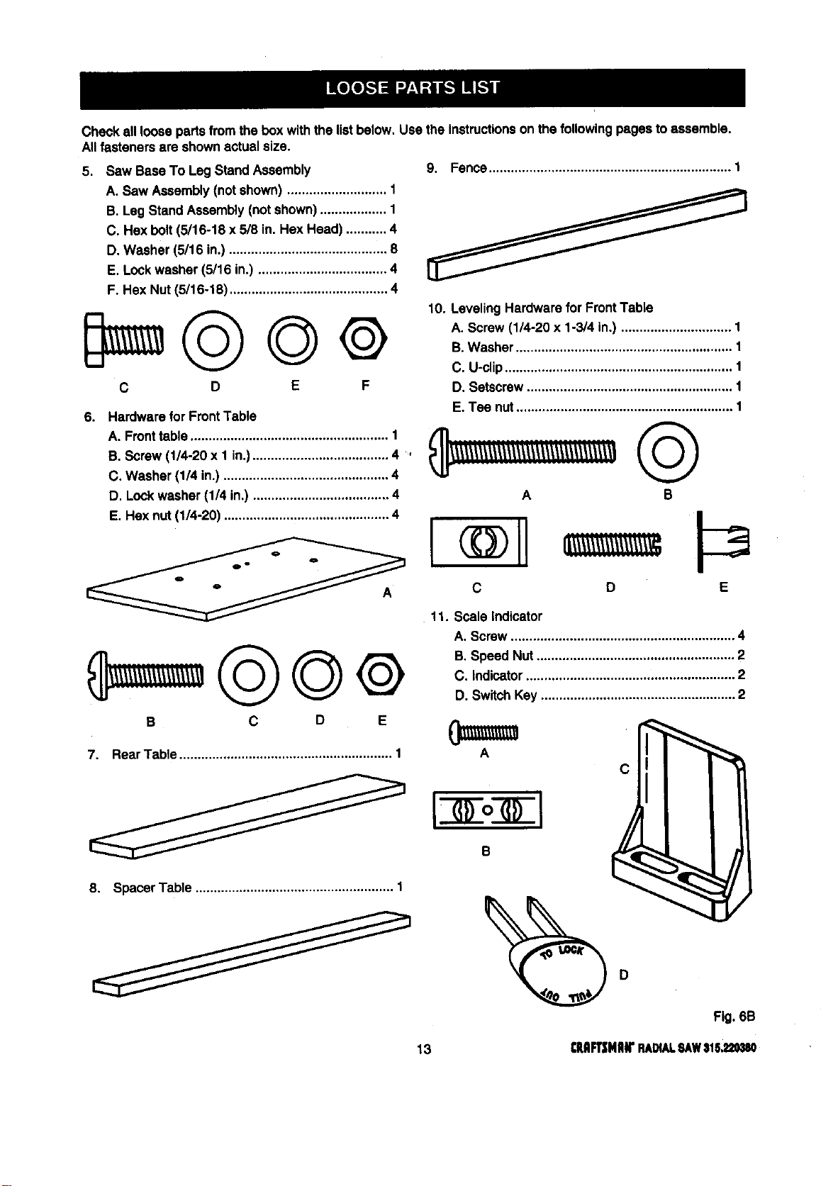
Check all loosepartsfrom the boxwith the listbelow. Usethe instructionson the followingpages toassemble.
Allfasteners are shownactual size.
12. Table Support
A. Table SupportRails ....................................... 2
B. Square head bolt(5/16-18 x 314in.).............. 4
C. Flatwasher (5/16 in,)..................................... 4
D. Lockwasher (5/18 in.) ................................... 4
E. Hex nut(5/16-18) ........................................... 4
©©.®
B C D E
13. Table Clamp....................................................... 2
A. Thumb screw(2) ............................................ 2
B. Squarenut ..................................................... 2
C. Table clampbracket ...................................... 2
D. Cupwasher.................................................... 2
B
c
14. Owner's Manual (notshown) ............................. 1
15.
Leg Stand ........................................................... 1
A. Leg ................................................................. 4
B. Long bottom brace ......................................... 2
C. Long top brace ............................................... 2
D. Shortbottom brace ........................................ 2
E, Short top brace .............................................. 2
F. Foot ................................................................ 4
G. Screw (1/4-20 x 5/8 in.) ............................... 40
H. Star washer .................................................. 40
I. Hex nut (1/4-20) ............................................ 40
J, Hex nut (3/8-16) .............................................. 8
o ol
ol
o o I
O( O0 J
G
H I J
Fig. 6C
[IIIIFI_NIIli" RADIALSAW315.220380 14
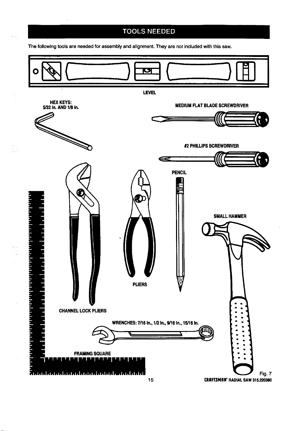
Thefollowingtoolsareneededforassemblyandalignment.Theyarenotincludedwiththissaw.
HEXKEYS:
S/32In.AND1/8in.
LEVEL
MEDIUMFLAT BLADESCREWDRIVER
#2PHILUPSSCREWDRIVER
PENCIL
SMALLHAMMER
C8
FRAMINGSQUARE
Fig. 7
15 ClUlFt'$MAI1"RADIALSAW315.220380
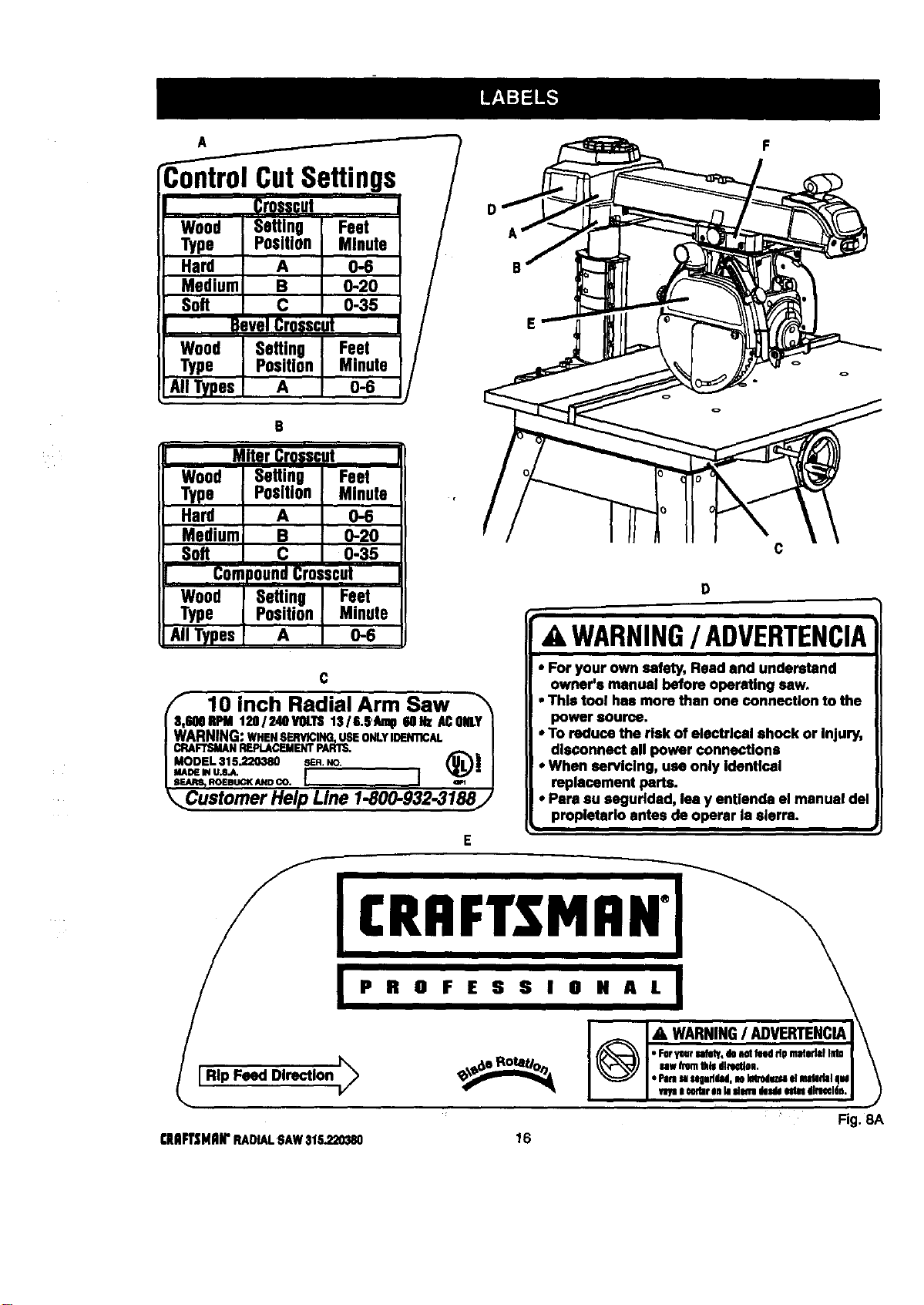
-ontrol CutSettings
Crospcut
Wood Seftlng Feet
Type Position Minute
Hard A 0-6
Medium B 0-20
Soft C 0-35
B,vel Cr0sscJt
Wood Setting Feet
Type Position Minute
All Types A 0-6
e
Wood I Setting Feet
Type [ Position Minute ,
Hard I A 0-6
Mediuml e
0-20
Soft I c
0-35
CompoundCr0=scot
Wood i Setting Feet
Type I Position Minute
S.IITypes A 0-6
D
F
C
10 inch Radial Arm Saw _'_
600RPM120/ 2410VOLTS1316.6'Aml16oez ACONLY[
RNING:WHENSERVICING,USEONLYIIDEN'I1CAL |
FTSMANREPLACEMENTPARTS, /
ROEBUCKANDCO, I ] wl J
sterner Help Line 1-800-932-3188/
c
WARNING/ ADVERTENCIA
• For your own safety, Read and understand
owner's manual before operating saw.
• This tool has more than one connection to the
power source.
• To reduce the risk of electrical shock or Injury,
disconnect all power connections
• When sarvlclng, usa only Identical
replacement parts.
• Para au segurldad, lea y entlenda el manual del
propletarlo antes de operar la sierra.
Fig. 8A
(HFT_;NRIrRADIALSAW316,220_10 16
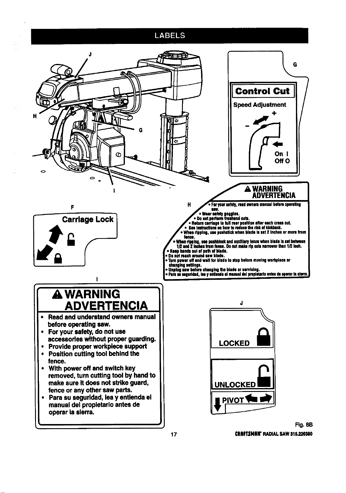
H
F
r- :rr'.e'ock1
AWARNING
ADVERTENCIA
• Read and understand owners manual
before operating sew.
• For your safety, do not use
accessories without proper guarding.
• Provide proper workplece support
• Position cutting tool behind the
fence.
• With power off and switch key
removed, turn cutting tool by hand to
make sure it does not strike guard,
fence or any other sew parts.
• Pare su segurlded, lea y entlenda el
manual del propletario antes de
operar is sierra.
Control Cu_t
On I
Ofre
i
' _ & WARNING
i_._,. ADVERTENClA
H._ F_pw sahd,/,read0Nm maualbeta.op_'_q
J" "War_ hqOlu.
f • Donotpedormfreehandeots.
J • Returncankigatofull rearpsaltisaaltereachcrossrut,
/ • SeeInotn_lonsollhawtoreducethe riskMM_.
i "men dpplng,usepus_ rosa blade_ sot2 InchesormoreDin
J _nu.
/ • WhimdbPlng,m p_l_ andauxiliarylamawhsabladeIssotbotlsa
f lf2 end2 inchesfromtom:o.Ohnotrake dp aidsnarrewerthan1/2 ioch,
r• Ksaphandsoutofpathof btoda,
, OnnotIHch nroungsawblade.
Turnpower offandwalt to_ bladetostopbeforemovingworkplaceor
changingsattlnp.
DUnglngsawbeforechangingthe bladeorsarviving,
, Paresasngultdad,lenyeotlendaelmsauotdviproplviadoantesde090mrhislofla
Fig. 8B
17 ClUiFl'|HlilrRADIALSAW316,320380
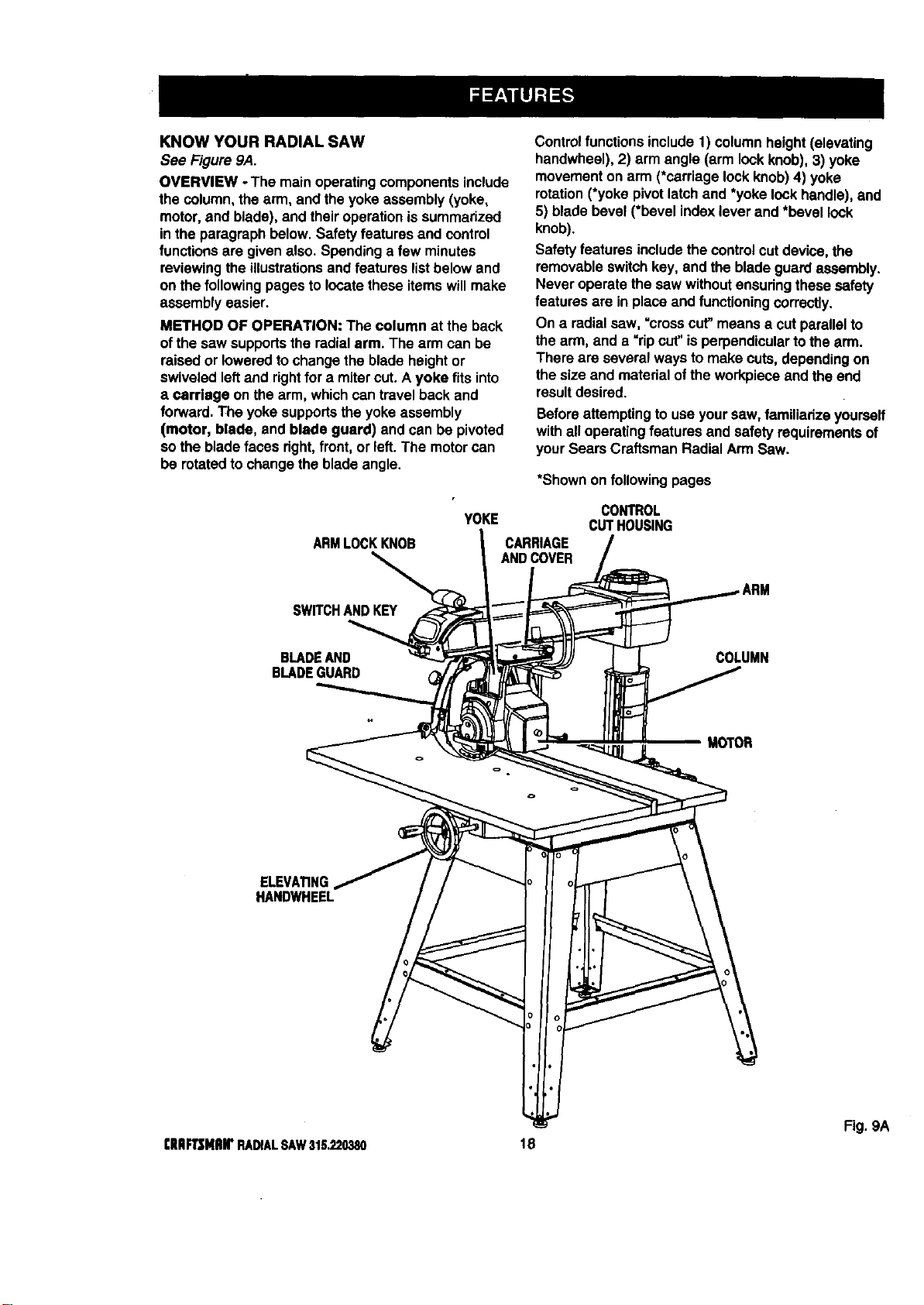
KNOWYOURRADIALSAW
See Figure9A.
OVERVIEW -The mainoperatingcomponentsinclude
the column,thearm, and the yokeassembly (yoke,
motor,and blade), and theiroperationissummarized
in theparagraph below. Safetyfeatures and control
functionsare givenalso. Spendinga few minutes
reviewingthe illustrationsand features list belowand
on the followingpages to locate these itemswillmake
assemblyeasier.
METHOD OF OPERATION: The column at the back
ofthe saw supportsthe radialarm. The armcan be
raisedor loweredto changethe bladeheightor
swiveledleftand rightfor a mitercut. A yoke fitsinto
a Carriage on the arm, whichcantravel back and
forward.The yokesupportsthe yokeassembly
(motor, blade, and blade guard) and can be pivoted
so the bladefaces right,front,or left. The motorcan
be rotatedto changethe blade angle.
Controlfunctions include1) column height(elevating
handwheel), 2) arm angle (arm lockknob),3) yoke
movementon arm (*carriagelockknob)4) yoke
rotation(*yoke pivotlatchand *yoke lockhandle),and
5) blade bevel (*bevel indexlever and *bevel lock
knob).
Safety features includethe controlcutdevice,the
removableswitchkey, and theblade guard assembly.
Never operatethe saw withoutensudngthese safety
features are in place and functioning correctly.
On a radialsaw, =crosscut"meansa cutparallelto
the arm, and a "ripcut' is perpendiculartothe arm.
There are several ways to make cuts, dependingon
thesize and materialofthe workpieceand the end
resultdesired.
Beforeattemptingtouse yoursaw,familiarize yoursaff
withall operatingfeatures and safety requirementsof
yourSears CraftsmanRadial Arm Saw.
*Shownon following pages
ARMLOCKKNOB
YOKE
CARRIAGE
ANDCOVER
CONTROL
CUTHOUSING
SWITCHANDKEY
BLADEAND
BLADEGUARD
COLUMN
MOTOR
ELEVA_NG
HANDWHEEL
Fig. 9A
[IIIIF'Ir$MRWRADIALSAW31S.220380 18
FEATURESLIST
See Figures9A-9D.
ADJUSTABLE TABLES - A narrowspacer table and
wider rear table thatcan be repositionedor even
replacedwith differenttables. See Figure 9C.
ANTI-KICKBACK PAWLS - Toothed pawlsthat snag
the workin case of kickbackduring ripcuts. (When
the blade isparallelto the arm, the pawls are in front
of theblade.) Keep the pawlsin placeto reduce risk
of injury.See Figure 9D.
ARM - The assemblyextendingfrom the column,
whichsupportsthe yoke, the motor,and the blade.
See Figure9A.
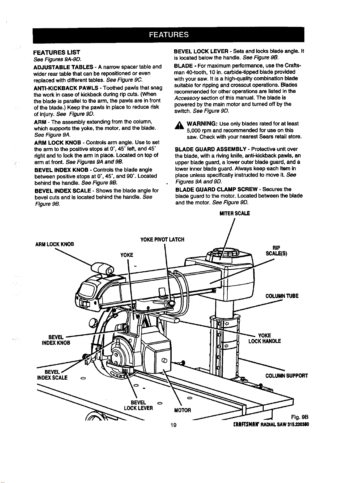
ARM LOCK KNOB - Controlsarm angle. Use toset
the armto the positivestopsat 0", 45" left,and 45"
rightand tolock the arm inplace. Locatedon top of
arm at front. See Figures9A and gB.
BEVEL INDEX KNOB - Controlsthe bladeangle
between positivestopsat 0", 45", and 90". Located
behindthe handle. See FiguregB.
BEVEL INDEX SCALE - Showsthe blade anglefor
bevel cutsand islocatedbehindthe handle. See
Figure9B.
BEVEL LOCK LEVER - Sets and locksbladeangle. It
islocatedbelowthe handle.See Figure9B.
BLADE - Formaximumperformance,use theCrafts-
man40-tooth, 10 in. carbide-tipped blade provided
withyoursaw. It isa high-qualitycombination blade
suitablefor rippingand crosscutoperations.Blades
recommendedfor otheroperationsare listedinthe
Accessorysectionof thismanual. The blade is
powered bythe main motorand turnedoffby the
switch.See Figure 9D.
_, WARNING: Use onlyblades ratedfor at least
5,000 rpm and recommendedfor useon this
saw. Check withyournearest Sears retailstore.
BLADE GUARD ASSEMBLY - Protectiveunitover
the blade, witha rivingknife,anti-kickbackpawls,an
upper blade guard,a lowerouter bladeguard, and a
lower innerblade guard.Alwayskeep each item in
place unlessspecificallyinstructedto moveit. See
Figures9A and 9D.
BLADE GUARD CLAMP SCREW - Secures the
blade guardtothe motor.Locatedbetween theblade
and the motor. See Figure9D.
MITERSCALE
ARMLOCKKNOB
YOKEPIVOTLATCH
YOKE
RIP
SCALE(S)
COLUMNTUBE
BEVEL
INDEXKNOB
YOKE
LOCKHANDLE
BEVEL
INDEXSCALE
ER
MOTOR
19
COLUMNSUPPORT
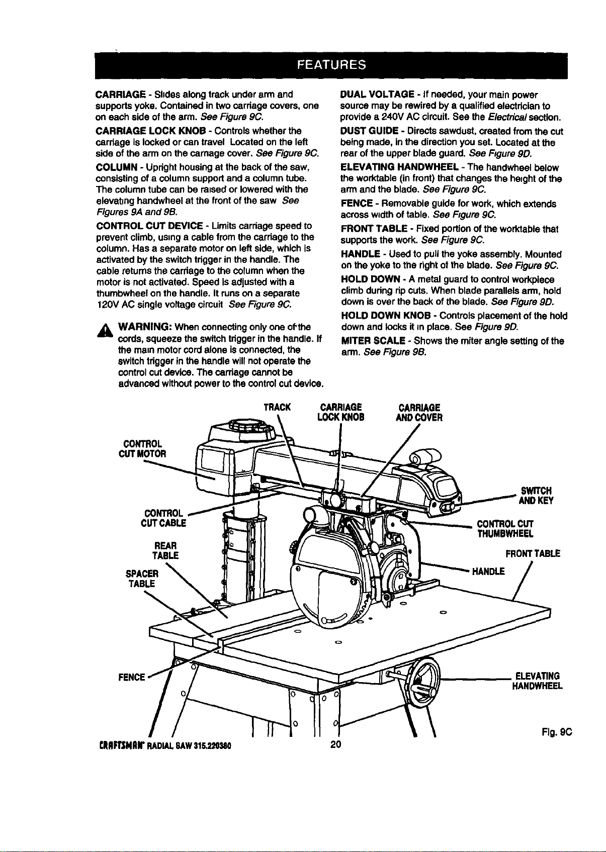
CARRIAGE-Shdesalongtrackunderarmand
supportsyoke. Containedin twocarriage covers,one
on each side ofthe arm. See Figure9C.
CARRIAGE LOCK KNOB - Controlswhetherthe
carriage islockedor can travel Locatedon the left
side ofthe arm on the carnagecover. See Figure9C.
COLUMN - Updghthousingat the backofthe saw,
consistingofa columnsupportand a column tube.
The columntube can be raisedor loweredwith the
elevating handwheelat the frontof the saw See
Figures9A and 9B.
CONTROL CUT DEVICE - Limitscarriagespeed to
preventclimb, usinga cable from the cardageto the
column.Has a separate motoron left side,whichis
activated bythe switchtriggerin the handle.The
cable returns thecarriage to thecolumnwhen the
motoris notactivated. Speed is adjustedwitha
thumbwheelon the handle. Itrunson a separate
120V AC singlevoltagecircuit See Figure9C.
_i, WARNING: When connecting onlyone of'the
cords,squeeze the switchtdggerinthe handle. If
the mare motorcordaloneisconnected, the
switchtriggerinthe handlewillnotoperatethe
controlcutdevice.The carriage cannot be
advancedwithoutpowertothecontrolcutdevice.
DUAL VOLTAGE - If needed, yourmain power
sourcemay be rewired bya qualifiedelectdcianto
providea 240V AC circuit. See the Electricalsection.
DUST GUIDE - Directssawdust,created fromthe cut
being made, inthe directionyou set. Locatedat the
rear ofthe upperblade guard. See Figure9D.
ELEVATING HANDWHEEL - The handwheelbelow
the worktable(in front)that changesthe heightof the
arm and the blade. See Figure 9C.
FENCE - Removable guide forwork,whichextends
across w_dthoftable, See Figure 9C.
FRONT TABLE - Fixed portionofthe worktablethat
supportsthe work.See Figure9C.
HANDLE - Used to pullthe yoke assembly.Mounted
on theyoke tothe rightof the blade. See Figure 9C.
HOLD DOWN - A metal guardto control workpiece
climbdudng ripcuts. When blade parallelsarm, hold
downis overthe back ofthe blade. See Figure9D.
HOLD DOWN KNOB - Controlsplacementofthe hold
downand locksitm place. See Figure 9D.
MITER SCALE - Shows the miterangle settingofthe
arm. See Figure 9B.
TRACK
CARRIAGE CARRIAGE
LOCKKNOB ANDCOVER
CONTROL
CUTMOTOR
CONTROL
CUTCABLE
REAR
TABLE
SPACER
TABLE
SWITCH
ANDKEY
CONTROLCUT
THUMBWHEEL
FRONTTABLE
FENCE
ELEVATING
HANDWHEEL
Fig. gC
qtlIIRSNRWRADIALSAW315.2L_B0 20
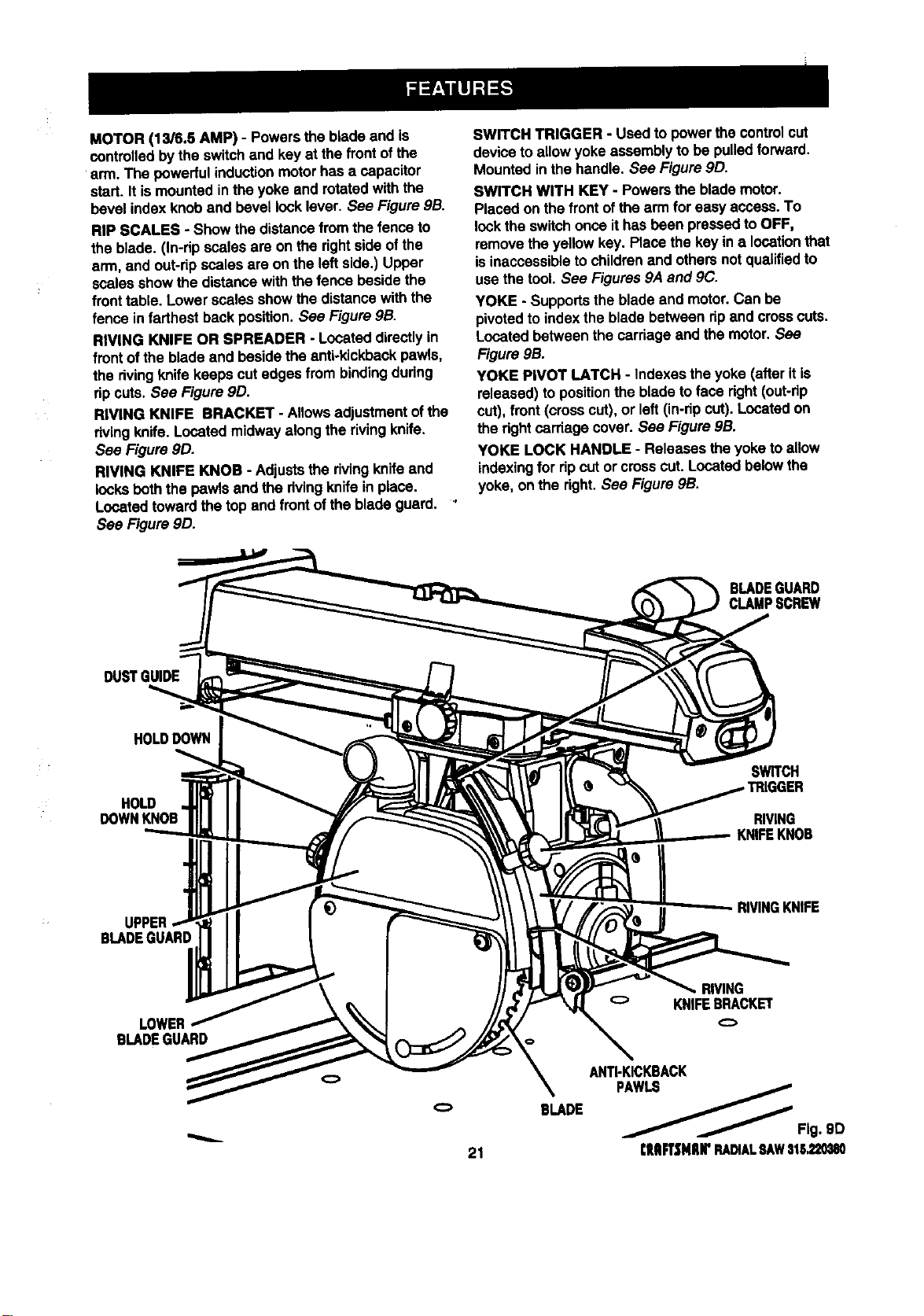
MOTOR(13/6.5AMP)-Powersthebladeandis
controlledbytheswitchand key at the frontof the
arm. The powerfulinductionmotorhas a capacitor
start. It is mountedinthe yoke and rotatedwith the
bevel indexknoband bevel locklever. See Figure9B.
RIP SCALES - Show the distancefrom the fenceto
the blade. (In-dp scales are on the rightside ofthe
arm, and out-ripscales are on the leftside.) Upper
scalesshow the distancewiththe fence besidethe
fronttable. Lowerscales showthe distancewith the
fence in farthest backposition.See Figure9B.
RIVING KNIFE OR SPREADER - Locateddirectlyin
front of the bladeand besidethe anti-kickbackpawls,
the rivingknife keepscut edges from bindingduring
ripcuts, See Figure9D.
RIVING KNIFE BRACKET - Allowsadjustmentofthe
dving knife.Locatedmidway along the rivingknife.
See Figure 9D.
RIVING KNIFE KNOB - Adjuststhe rivingknifeand
locksbeth the pawls and the rivingknife in place.
Locatedtowardthe top andfront ofthe blade guard. '
See Figure 9D.
SWITCH TRIGGER - Used topower thecontrolcut
deviceto allowyoke assemblyto be pulledforward.
Mountedin the handle. See Figure9D.
SWITCH WITH KEY - Powersthe blademotor.
Placed onthe frontofthe arm for easy access.To
locktheswitchonce ithas been pressedtoOFF,
removethe yellowkey. Place the key in a locationthat
isinaccessibleto childrenand othersnotqualifiedto
use thetool. See Figures9A and 9C.
YOKE - Supportsthe blade and motor.Can be
pivotedto indexthe bladebetween ripand crosscuts.
Locatedbetween the carriage and the motor. See
Figure 9B.
YOKE PIVOT LATCH - indexesthe yoke (afterit is
released) to positionthe blade toface right(out-rip
cut), front(crosscut), or left(in-ripcut). Locatedon
the rightcardage cover. See Figure9B.
YOKE LOCK HANDLE - Releases the yoketo allow
indexingfor ripcut orcross cut. Locatedbelowthe
yoke, on the right.See Figure 9B.
DUSTGUIDE
HOLDDOWN
HOLD
DOWNKNOB
SWITCH
RIVING
UPPER
BLADEGUARD :
RIVINGKNIFE
LOWER
BLADEGUARD
21
BLADE
RIVING
o KNIFEBRACKET
ANTI-KICKBACK
__ Fig. 9D
rlUIFTSNIIWRADIALSAWStl;_mSO
Assemblyisbestdone in the areawhere thesaw will
be used. When you removethe saw and hardware
fromthe packingmatedals, carefullycheckthe items
withthe Loose Partslist.If you are unsureabout the
descriptionof any part,refer to theirillustrations.For
yourconvenience,all fasteners have been drawn
actual size. Ifany pads are missing,delay assembling
untilyou have obtainedthe missingpart(s).
Yourradial arm saw iscapable ofa wide varietyof
operations,and thus requiresa numberof initialsetup
adjustments.However, once the saw isset up,you
cancheck yoursaw in aboutten minutesand correct
any misalignmentwiththe proceduresin the Adjust-
mentsection.
CAUTION: Performall the proceduresin both
the Assemblyand Adjustmentssectionsbefore
usingthe saw. Runa checkon yoursaw
frequently,referringtothe Adjustmentssection.
Failureto performthe adjustmentsin the initial
set up or on a frequentbasiscan resultinpoor
performanceor machinedamage.
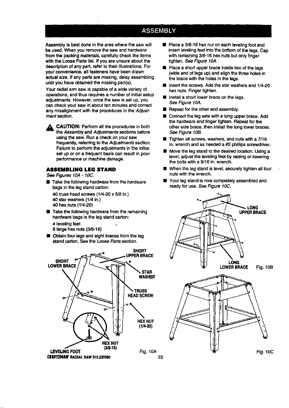
ASSEMBLING LEG STAND
See Figures 10,4- IOC.
• Take the followinghardwarefromthe hardware
bags inthe leg standcarton:
40 trusshead screws(1/4-20 x 5/8 in.)
40 starwashers(1/4 in.)
40 hex nuts(1/4-20)
• Take thefollowinghardwarefromthe remaining
hardwarebags in the legstand carton:
4 levelingfeet
8 largehex nuts(3/8-16)
• Obtainfourlegsand eightbraces fromthe leg
stand carton. See theLoosePartssection.
• Placea 3/8-16 hex nuton each levelingfootand
insertlevelingfeet intothe bottom ofthe legs.Cap
with remaining3/8-16 hex nutsbutonlyfinger
tighten.See Figure 10,4.
• Place a shortupperbrace insidetwoof thelegs
(wideend oflegs up)and alignthethree holesin
the brace withthe holesinthe legs.
• Insertthe screws.Addthe starwashersand 1/4-20
hex nuts.Fingertighten.
• Installa shortlowerbrace onthe legs.
See Figure IOA.
• Repeat forthe otherend assembly.
• Connectthe leg setswith a longupperbrace.Add
the hardwareand finger tighten.Repeat for the
otherside brace,then installthe longlowerbraces.
See Figure lOB.
• Tightenall screws,washers,and nutswitha 7/16
in.wrenchand as needed a #2 phillipsscrewdriver.
• Move the leg standtothe desiredlocation.Usinga
level,adjustthe levelingfeet by raisingorlowering
theboltswitha 9/16 in. wrench.
• When the leg stand islevel,securelytighten all four
nutswiththe wrench.
• Your legstand isnowcompletelyassembledand
readyfor use. See Figure 10C.
LONG
UPPERBRACE
SHORT
SHORT
LOWERBRACE
;TAR
WASHER
HEADSCREW
HEXNUT
(1_-20)
HEXNUT
(3/8-16)
I.EVEUNGFOOT Fig. 10A
I:RIIR3MIIWRADIALSAW315.220380 22
LONG
LOWERBRACE Fig. lOB
Fig. 10C
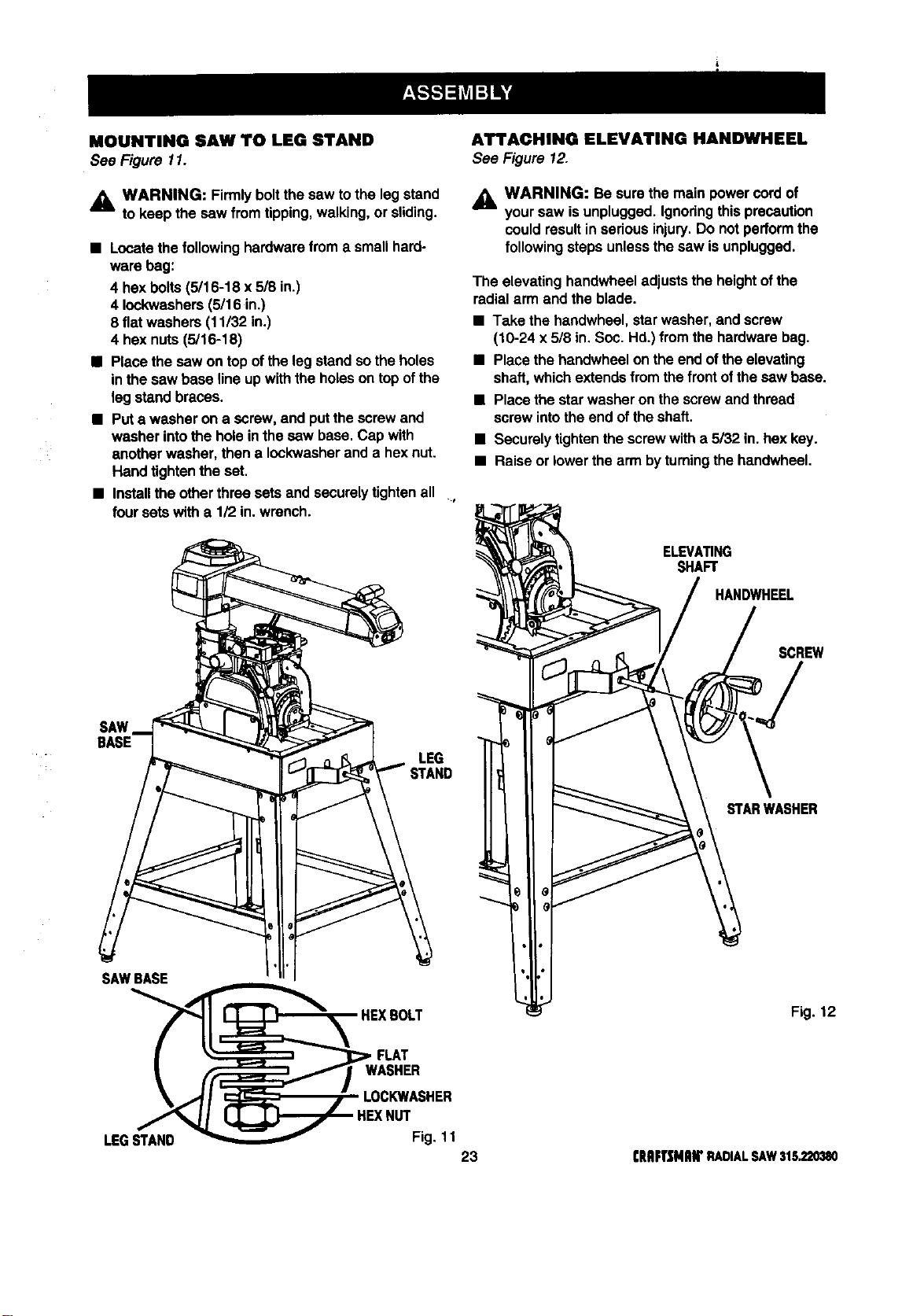
MOUNTING SAW TO LEG STAND
See Figure 11.
,_ WARNING: Firmlyboltthe saw tothe leg stand
to keep the saw from tipping,walking,or sliding.
• Locatethefollowinghardwarefroma smallhard-
ware bag:
4 hexboils (5/16-18 x 5/8 in.)
4 Iockwashers(5/16 in.)
8 flatwashers (11/32 in.)
4 hex nuts(5/16-18)
• Place the saw on top ofthe legstand sothe holes
in the saw base lineup withthe holeson top ofthe
leg standbraces.
• Puta washer on a screw,and put thescrewand
washer intothe holein thesaw base. Cap with
another washer,then a Iockwasherand a hex nut.
Hand tightenthe set.
• Installthe otherthree setsand securelytightenall ,
foursets witha 1/2 in.wrench.
An'ACHING ELEVATING HANDWHEEL
See Figure 12.
_1= WARNING: Be surethe main powercordof
yoursaw is unplugged.Ignodngthisprecaution
could resultin seriousinjury.Do not performthe
followingstepsunlessthe saw is unplugged.
The elevating handwheeladjuststhe heightofthe
radialarm and the blade.
• Take the handwheel,starwasher,and screw
(10-24 x 5/8 in.Soc. Hd.) from the hardwarebag.
• Placethe bandwheel on the end oftheelevating
shaft,whichextendsfromthe front ofthe saw base.
• Placethe starwasher on thescrewand thread
screwintothe end ofthe shaft.
• Securelytightenthe screwwitha 5/32 in.hex key.
• Raiseor lowerthe armby turningthe handwheel.
ELEVATING
SHAFT
HANDWHEEL
SCREW
SAW
BASE
LEG
_TANO
STARWASHER
SAWBASE
Fig. 12
FLAT
LEGSTAND
HEXNUT
Fig. 11
23 CRRFTJ[MIIWRADIALSAW315,220380
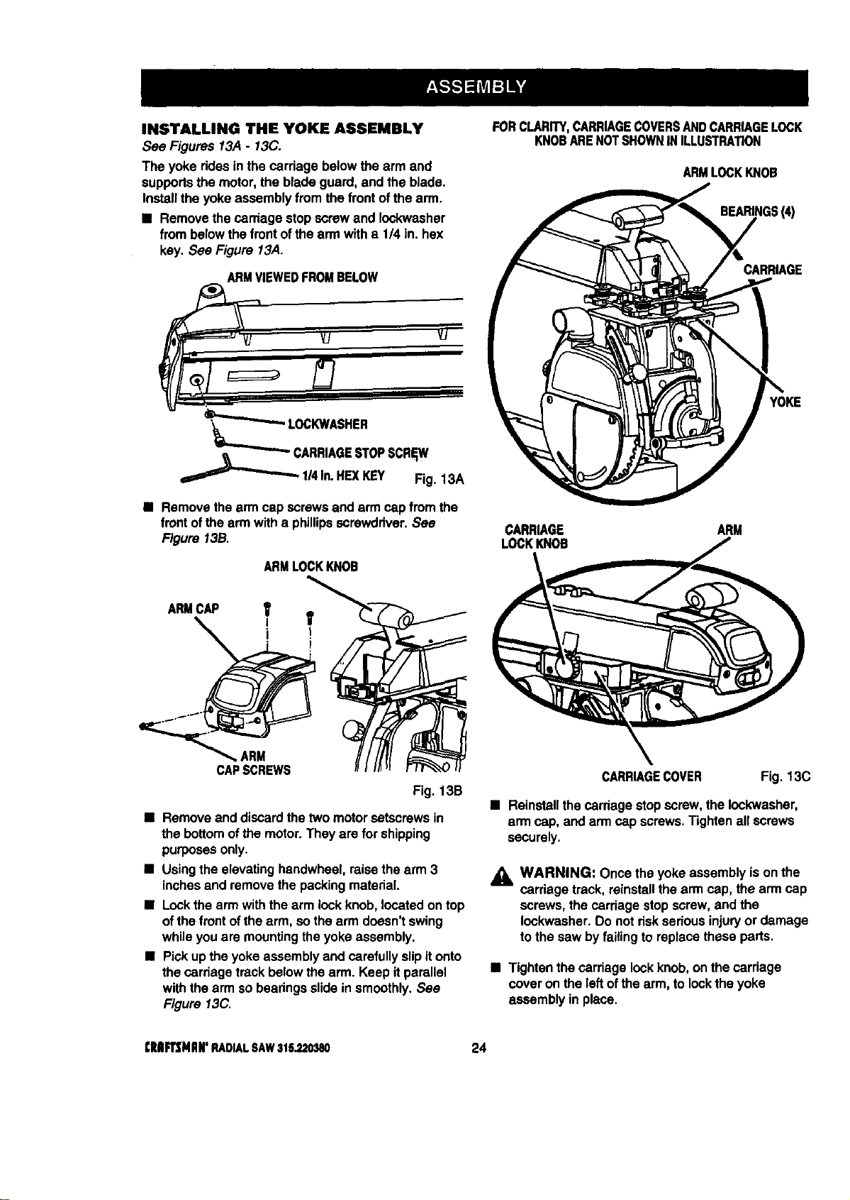
INSTALLING THE YOKE ASSEMBLY
See Figures 13A - 13C.
The yoke ridesin the carriage belowthe armand
supportsthe motor,the blade guard,and the blade.
Installthe yokeassembly fromthe frontofthe arm.
• Removethe carriage stop screwand Iockwasher
from belowthe frontof thearm witha 1/4 in.hex
key.See Figure 13A.
ARMVIEWEDFROMBELOW
FORCLARITY,CARRIAGECOVERSANDCARRIAGELOCK
KNOBARENOTSHOWNINILLUSTRATION
ARMLOCKKNOB
BEARINGS(4)
CARRIAGE
_CARRIAGE STOPSCREW
1/4In.HEXKEY Fig. 13A
• Removethe arm cap screws and arm capfromthe
frontofthe armwith a phillipsscrewdriver, See
Figure 13B.
ARMCAP
ARM
CAPSCREWS
ARMLOCKKNOB
Fig. 13B
• Remove and discardthetwo motorsetscrewsin
thebottomof themotor.They arefor shipping
purposesonly.
• Usingthe elevatinghandwheel,raisethe arm 3
inchesand removethe packingmaterial.
• Lockthe armwiththe arm lockknob,locatedon top
ofthe front ofthe arm, so thearm doesn'tswing
whileyouare mountingthe yokeassembly.
• Pickupthe yokeassemblyand carefullyslipit onto
thecarriage track belowthearm. Keep itparallel
withthe arm sobearingsslidein smoothly,See
Figure 13C.
YOKE
CARRIAGE ARM
LOCKKNOB
CARRIAGECOVER Fig. 13C
• Reinstallthe cardage stopscrew,the Iockwasher,
armcap, and armcap screws,Tightenall screws
securely.
_IL WARNING: Oncethe yoke assemblyis onthe
carriage track, reinstallthearm cap, thearm cap
screws, the carriagestop screw,and the
Iockwasher.Do not riskserious injuryor damage
to the saw byfailingtoreplace these parts.
• Tightenthecarriage lockknob,on thecarriage
cover on the leftofthearm, to locktheyoke
assembly in place.
[Rlllrl3MIIIr RADIALSAW316_20380 24
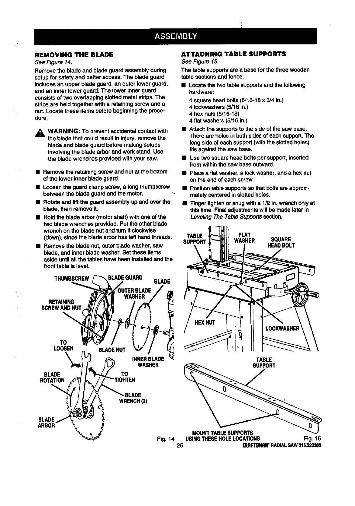
REMOVING THE BLADE
See Figure 14.
Remove the blade and blade guard assemblyduring
setupfor safety and betteraccess.The blade guard
includesan upper bladeguard,an outerlowerguard,
and an inner lowerguard. The lowerinnerguard
consistsoftwo overlappingslottedmetalstrips.The
stripsare heldtogetherwith a retainingscrewand a
nut. Locatethese itemsbeforebeginningthe proce-
dure.
_i, WARNING: To preventaccidentalcontactwith
the bladethat couldresultin injury,remove the
blade and blade guard beforemakingsetups
involvingthe bladearbor and workstand. Use
the bladewrenches providedwithyour saw.
• Remove the retainingscrew and nut at thebottom
ofthe lowerinnerblade guard.
• Loosenthe guardclamp screw,a longthumbscrew
between the bladeguard andthe motor.
• Rotateand liftthe guardassembly up and overthe
blade, then remove it.
• Holdthe blade arbor (motorshaft) withone ofthe
two bladewrenchesprovided.Putthe otherblade
wrenchonthe blade nutand turnit clockwise
(down), sincethe bladearborhas lefthandthreads.
• Remove the bladenut,outerbladewasher, saw
blade, and innerbladewasher.Set these Items
aside untilall thetables have bean installedand the
fronttable islevel.
THUMBSCREW
BLADE
RETAINING
SCREWANDNUT
TO
LOOSEN
\
BLADE
ROTATION
BLADENUT
TO
INNERBLADE
WASHER
BLADE
WRENCH(2)
BLADE
ARBOR _'_
ATTACHING TABLE SUPPORTS
See Figure 15.
The table supportsare a basefor the three wooden
table sectionsand fence.
• Locatethetwo table supportsand thefollowing
hardware:
4 squarehead bolts(5/16-18 x 3/4 in.)
4 Iockwashers(5/16 in.)
4 hexnuts (5/16-18)
4 flat washers(5/16 in.)
• Attachthe supportstotheside ofthesaw base.
There are holesin bothsidesof eachsupport.The
longsideofeach support(withthe slottedholes)
fitsagainstthesaw base.
B Use two squarehead boltsper support,inserted
from withinthe saw baseoutward.
• Place a fiatwasher,a lockwasher,and a hex nut
on the end ofeachscrew.
• Positiontable supportsso thatboltsare approxi-
matelycenteredin slottedholes.
• Fingertightenorsnugwitha 1/2 in.wrenchonlyat
thistime. Finaladjustmentswillbemade later in
LevelingThe Table Supportssection.
TABLE FLAT
SUPPORT WASHER SQUARE
HEAl)BOLT
TABLE
SUPPORT
MOUNTTABLESUPPORTS
Fig, 14 USINGTHESEHOLELOCATIONS Fig. 1B
25 rltRFTSNRB"RADIALSAW315.220_I0
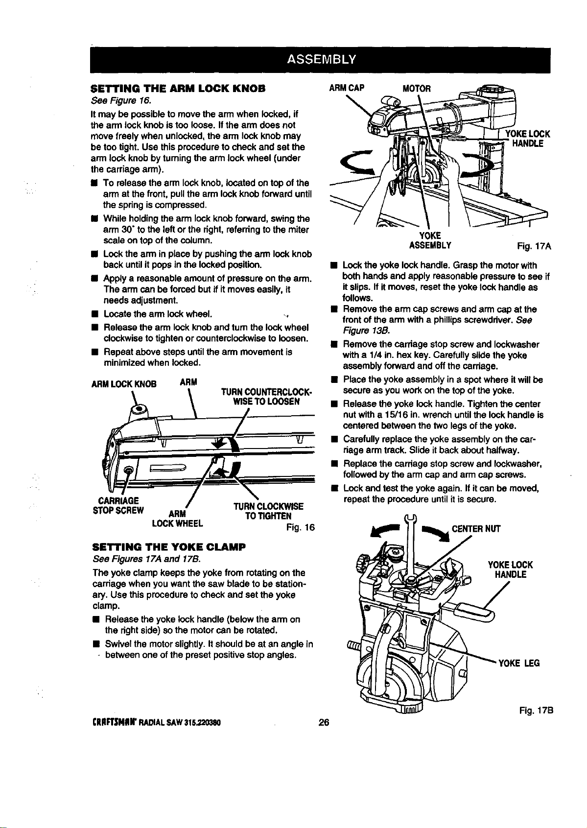
SET'rING THE ARMLOCKKNOB
See Figure 16.
It may be possibleto movethe arm when locked,if
the arm lockknobistoo loose•Ifthe arm does not
move freely when unlocked,the arm lock knobmay
be too tight. Use thisproceduretocheck and set the
arm lock knobbyturningthe arm lock wheel (under
the carriage arm).
• To releasethe arm lockknob,locatedon topof the
arm at the front,pullthe arm lockknobforwarduntil
thespringiscompressed.
• While holdingthearm lockknobforward,swingthe
arm 30"tothe leftorthe right,referring tothe miter
scaleon top ofthe column.
• Lockthe arm in placeby pushingthearm lockknob
back untilit popsin the lockedposition.
• Applya reasonableamountof pressureonthe arm.
The armcan be forcedbutif itmoveseasily,it
needs adjustment.
• Locatethearm lockwheel. _,
• Release the arm lockknoband turnthe lockwheel
clockwisetotightenor countemiockwise to loosen.
• Repeat above stepsuntilthe arm movementis
minimizedwhen locked.
ARMLOCKKNOB
ARM
TURNCOUNTERCLOCK-
WISETOLOOSEN
CARRIAGE
TURNCLOCKWISE
STOPSCREW ARM TOTIGHTEN
LOCKWHEEL Fig. 16
SET'rING THE YOKE CLAMP
See Figures 17.4and 17B.
The yokeclamp keeps the yokefrom rotatingon the
carriage when you wantthe saw blade to be station-
ary. Use thisproceduretocheck and set the yoke
clamp.
• Release the yokelock handle(belowthe armon
the dghtside) so the motorcan be rotated.
• Swivelthe motorslightly•Itshouldbe at an angle in
• between one ofthe presetpositivestopangles.
ARMCAP MOTOR
YOKELOCK
HANDLE
YOKE
ASSEMBLY
Fig. 17A
• Lockthe yoke lockhandle.Graspthe motorwith
bothhandsand apply reasonablepressuretosee if
itslips.If itmoves, resettheyokelock handleas
follows.
• Remove thearm cap screwsand arm capat the
front ofthe armwith a phillipsscrewdriver.See
Figure 13B.
• Remove thecardage stopscrewand Iockwasher
with a 1/4 in. hex key.Carefullyslidethe yoke
assemblyforwardand offthe carriage.
• Placetheyoke assemblyin a spotwhere itwillbe
secure as you workon thetop oftheyoke.
• Release theyoke lockhandle.Tightenthecenter
nutwith a 15/16 in.wrenchuntilthe lockhandleis
centeredbetween the two legsofthe yoke.
• Carefullyreplacetheyoke assemblyon the car-
riagearm track.Slide itbackabouthalfway.
• Replacethecardage stopscrew and Iockwasher,
followed bythe armcap and arm cap screws.
• Lockand test the yokeagain. Ifitcan be movsd,
repeatthe procedureuntilitissecure.
_ CENTERNUT
YOKELOCK
HANDLE
LEG
Fig. 17B
[lUlFT|NIIIrRADIALSAW315.220380 26
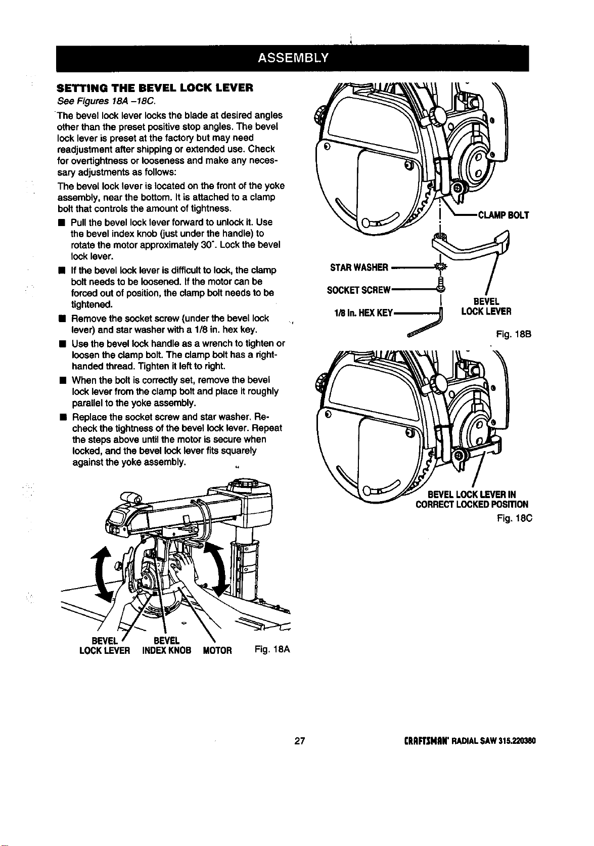
SETTINGTHE REVEL LOCK LEVER
See Figures 18A-18C,
The bevel lock lever locksthe blade at desired angles
otherthan the preset positivestop angles.The bevel
lock lever ispreset at the factorybut may need
readjustmentafter shippingor extended use. Check
for overtightnessor loosenessand make any neces-
sary adjustmentsas follows:
The bevel locklever is locatedon the frontof the yoke
assembly, near the bottom.It isattachedto a clamp
boltthat controlsthe amountof tightness.
• Pullthe bevel locklever forwardto unlockit. Use
the bevel indexknob(justunderthe handle)to
rotatethe motorapproximately30".Lockthe bevel
locklever.
• Ifthe bevel locklever isdifficultto lock,the clamp
boll needsto be loosened,ifthe motorcan be
forcedoutof position,theclamp boltneeds to be
tightened.
• Remove the socketscrew(underthe bevellock
lever) and starwasher witha 1/8 in.hexkey.
• Use the bevel lockhandle as a wrenchto tightenor
loosenthe clamp bolt.The clamp belt has a right-
handedthread. Tightenitleftto right.
• When the boltiscorrectlyset, removethe bevel
locklever fromthe clampboil and place itroughly
paralleltotheyoke assembly.
• Replacethesocketscrewand starwasher, Re-
checkthe tightnessofthe bevellocklever. Repeat
the stepsabove untilthe motorissecure when
locked,and thebevel locklever fitssquarely
againstthe yokeassembly.
STARWASHER
SOCKETSCREW'_'_
I
1/8In.HEXKEym----_
BEVEL
LOCKLEVER
Fig. 18B
BEVEL BEVEL
LOCKLEVER INDEXKNOB MOTOR Fig. 18A
BEVELLOCKLEVERIN
CORRECTLOCKEDPOSITION
Fig, 18C
27 (RIIFT_[NAN"RADIALSAW315,220380
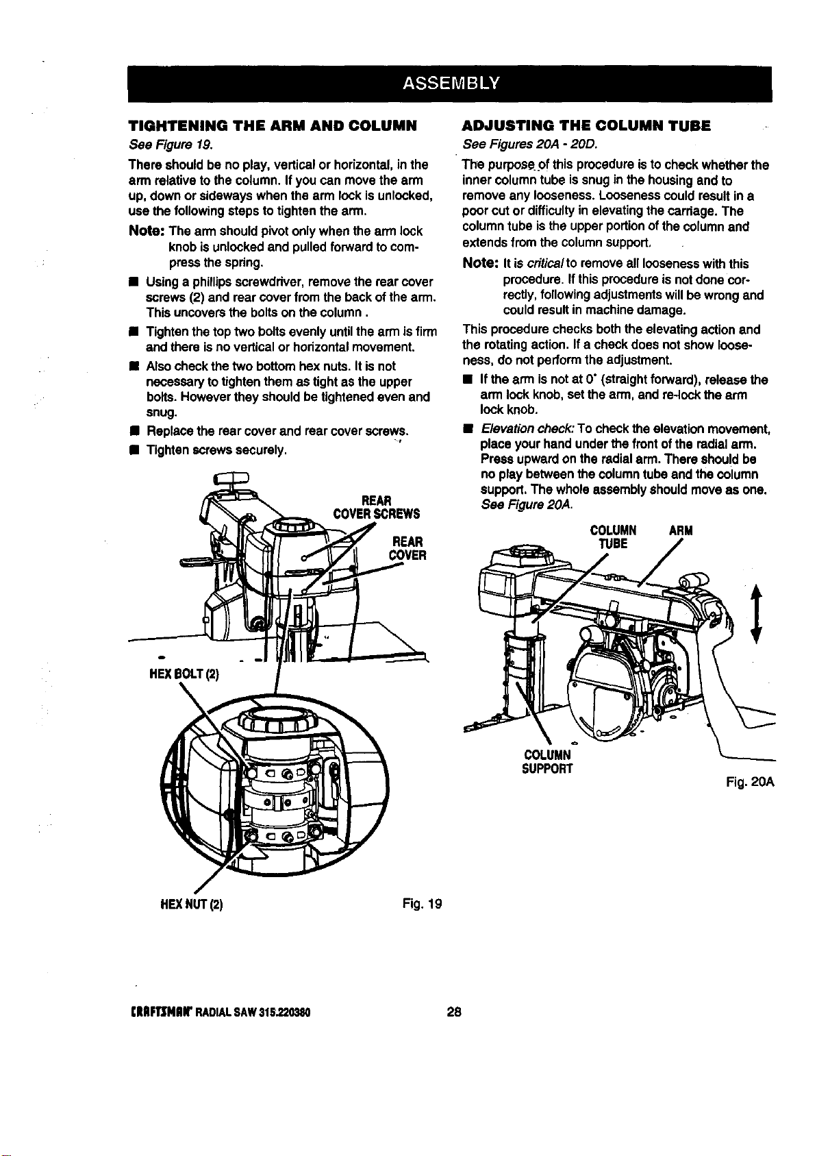
TIGHTENING THE ARM AND COLUMN
See Figure 19.
There shouldbe no play,verticalor horizontal,in the
arm relativeto the column.If youcan movethe arm
up, downor sidewayswhen the arm lockis unlocked,
use the followingstepsto tightenthe arm,
Note: The arm shouldpivotonlywhen the armlock
knobisunlockedand pulledforwardto com-
pressthe spdng.
• Usinga phillipsscrewdriver,removethe rear cover
screws(2) and rear coverfrom the backof thearm.
This uncoversthe boltson the column.
• Tightenthetop twobolts evenly untilthe arm isfirm
and there isno verticalor horizontalmovement.
• Alsocheckthetwo bottomhex nuts.Itis not
necessarytotightenthem as tightas the upper
bolts.Howeverthey shouldbe tightenedeven and
snug.
• Replacethe rear cover and rear coverscrews.
• Tightenscrews securely.
REAR
COVERSCREWS
REAR
COVER
HEXBOLT(2)
ADJUSTING THE COLUMN TUBE
See Figures20A - 20D.
The purpos¢.pfthis procedureisto checkwhetherthe
inner column tube issnugin the housingand to
remove any looseness.Loosenesscould resultin a
poorcut or difficultyin elevatingthe carriage. The
columntube isthe upperportionofthecolumnand
extendsfrom the columnsupport,
Note: It iscrftica/to removeall loosenesswiththis
procedure.Ifthisprocedureisnotdone cor-
rectly,followingadjustmentswillbe wrongand
couldresultin machinedamage.
This procedurechecksboththeelevatingactionand
the rotatingaction. Ifa checkdoes not show loose-
ness, do not performthe adjustment.
• Ifthe arm isnotat O"(straightfonNard), release the
armlock knob,set thearm, and re-lockthe arm
lockknob.
• Elevationcheck:To checkthe elevationmovement,
placeyourhand underthe frontofthe radialarm.
Pressupwardon the radialarm.There shouldbe
no play betweenthe column tubeand the column
support.The wholeassembly shouldmoveas one.
See Figure20A.
COLUMN ARM
TUBE
COLUMN
SUPPORT
Fig. 20A
HE](NUT(2)
Fig. 19
(lUlF1]MIIW RADIALSAW316.220380 28
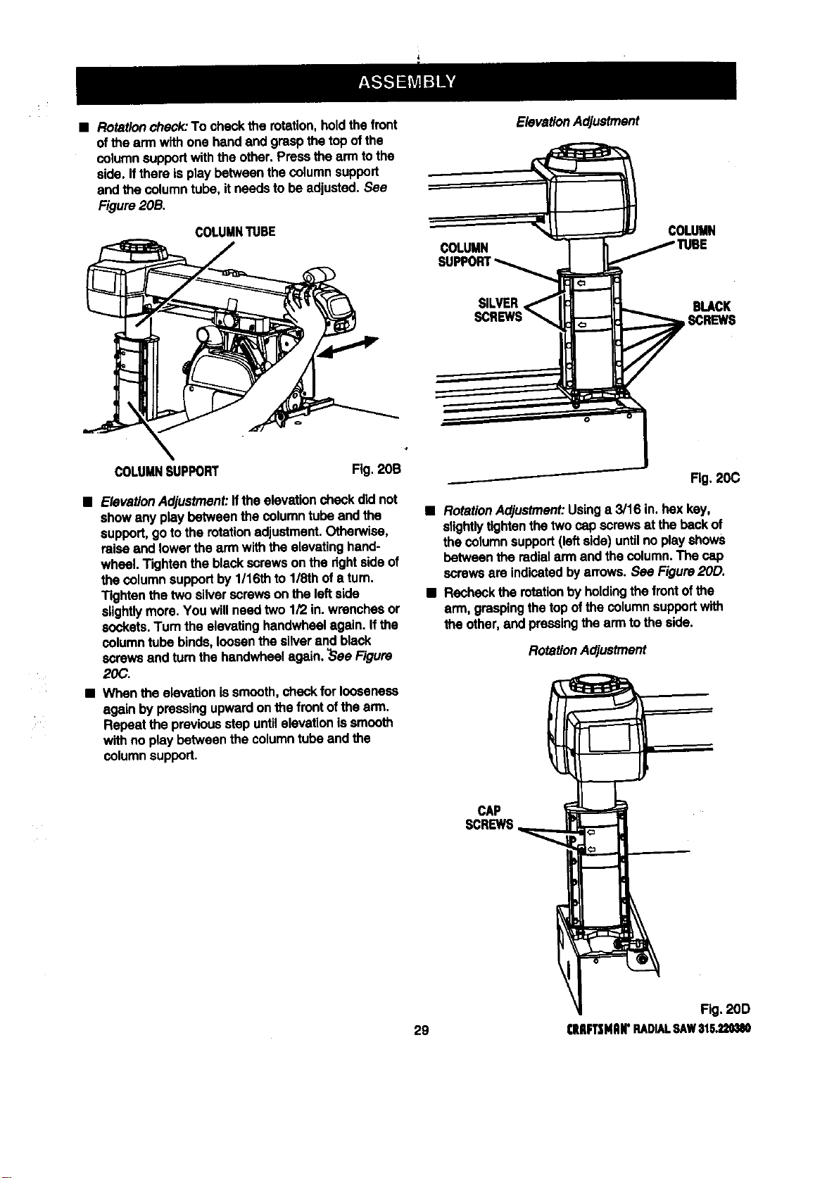
• Rotationcheck:To checkthe rotation, holdthe front
ofthe ann withone handand graspthetop ofthe
columnsupportwiththe other.Pressthe arm tothe
side.If there isplay between thecolumn support
and the columntube, itneeds tobe adjusted.See
Figure20B.
COLUMNTUBE
ElevationAdjustment
COLUMN
COLUMN
SILVER BLACK
SCREWS
COLUMNSUPPORT Fig, 20B
• ElevationAdjustment:Ifthe elevationcheckdidnot
showany play between the columntube and the
support,goto the rotationadjustment.Otherwise,
raiseand lowerthe ann withthe elevatinghand-
wheel. Tightenthe blackscrewsonthe rightsideof
the columnsupportby 1/16th to1/8th of a turn.
Tightenthe twosilverscrews on the leftside
slightlymore.You willneedtwo 1/2 in.wrenchesor
sockets.Turn the elevatinghandwhselagain. If the
columntube binds,loosenthe silverand black
screwsand tum the handwheelagain. ?SeeFigure
20C.
• Whenthe elevationis smooth,check for looseness
again bypressingupwardon the frontofthe arm.
Repeat the previousstep untilelevationis smooth
withno play between the columntube and the
columnsupport.
Fig. 20C
• RotationAdjustment:Usinga 3/16 in.bax key,
slightlytightenthe twocap screwsat thebackof
the columnsupport(leftside) untilno playshows
between the radialarm and the column. The cap
screws are indicatedby arrows.See Figure20D.
• Recheckthe rotationbyholdingthe frontofthe
arm, graspingthetop ofthe columnsupportwith
the other,and pressingthe ann tothe side.
RotationAdjustment
CAP
SCREWS
Fig. 2OD
29 CIIIIFTSNAI('RADIALRAW$1S.,_
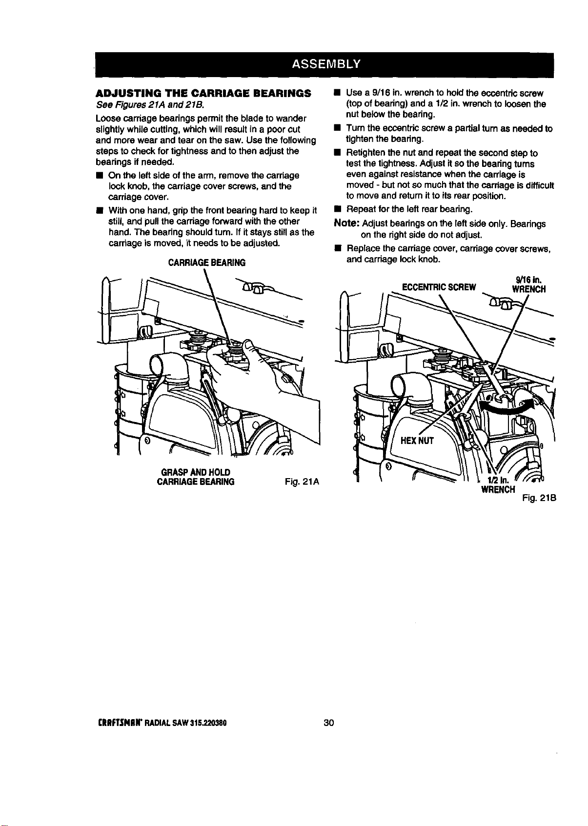
ADJUSTING THE CARRIAGE BEARINGS
See Figures21A and 215.
Loosecarriage bearingspermitthe blade towander
slightlywhile cutting,whichwillresultin a poorcut
and more wear and tear on the saw. Use thefollowing
stepsto checkfortightnessand tothen adjustthe
beadngs ifneeded.
• On the leftside ofthe arm, removethecarriage
lockknob,the carriage coverscrews,and the
carriage cover.
• Withone hand,grip thefrontbearinghardto keep it
still,and pullthecarriage forwardwiththe other
hand. The beadng shouldturn. If itstaysstillas the
carriage is moved, it needsto be adjusted.
CARRIAGEBEARING
• Use a 9/16 in.wrenchto holdtheeccentricscrew
(top ofbeadng) and a 1/2 in.wrenchtoloosenthe
nut belowthe bearing.
• Turn the eccentricscrewa partialturnas neededto
tightenthe bearing.
• Retightenthenut and repeatthe secondstepto
testthe tightness.Adjustif sothe bearingturns
even againstresistancewhenthe carriage is
moved- butnot somuchthatthe carriage isdifficult
to moveand retum itto itsrear position.
• Repeat for theleft rearbearing.
Note: Adjustbearingson the leftside only. Bearings
on the rightsidedo notadjust.
• Replace thecarriage cover,carriage coverscrews,
and carriagelockknob.
9/16In.
ECCENTRICSCREW WRENCH
GRASPANDHOLD
CARRIAGEBEARING
Fig. 21A
WRENCH
Fig. 21B
I;RIIFTSNIIN"RADIALSAW315.220380 30
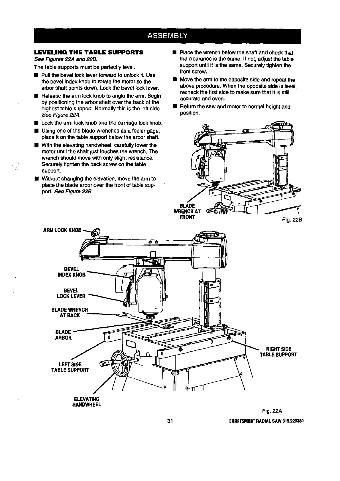
LEVELING THE TABLE SUPPORTS
See Figures 22,4 and 22B.
The table supportsmustbe perfectlylevel.
• Pullthe bevel locklever forwardtounlockit. Use
the bevel indexknobto rotatethemotorso the
arborshaft pointsdown. Lockthe bevel lock lever.
• Release the arm lockknobtoangle thearm. Begin
bypositioningthe arborshaftover the backof the
highesttable support.Normallythis isthe leftside.
See Figure 22,4.
• Lockthe arm lockknoband thecardage lockknob.
• Usingone of the bladewrenchesas a feeler gage,
place iton thetable supportbelowthearbor shaft.
• Withthe elevating handwheel,carefullylowerthe
motoruntilthe shaftjust touchesthe wrench.The
wrenchshouldmovewithonlyslightresistance.
Securelytightenthe backscrewon the table
support.
i Withoutchangingthe elevation,movethearm to
place the bladearbor over thefrontoftable sup- '
port. See Figure22B.
Place thewrenchbelowthe shaftand checkthat
the clearanceisthesame. Ifnot,adjustthe table
supportuntilitisthe same, Securelytightenthe
frontscrew,
• Movethe arm tothe oppositeside and repeat the
above procedure.When the oppositeside islevel,
recheckthe firstsideto make surethat itisstill
accurate and even.
• Returnthesaw and motortonormalheightand
position.
BLADE
WRENCHAT
FRONT Fig. 22B
BEVEL
INDEXKNOB
BEVEL
LOCKLEVER
BLADEWRENCH
ATBACK
BLADE
ARBOR
LEFTSIDE
TABLESUPPORT
RIGHTSIDE
TABLESUPPORT
ELEVATING
HANDWHEEL
Fig. 22A
31 [IIRFTSHRII"RADIALSAW315.220380
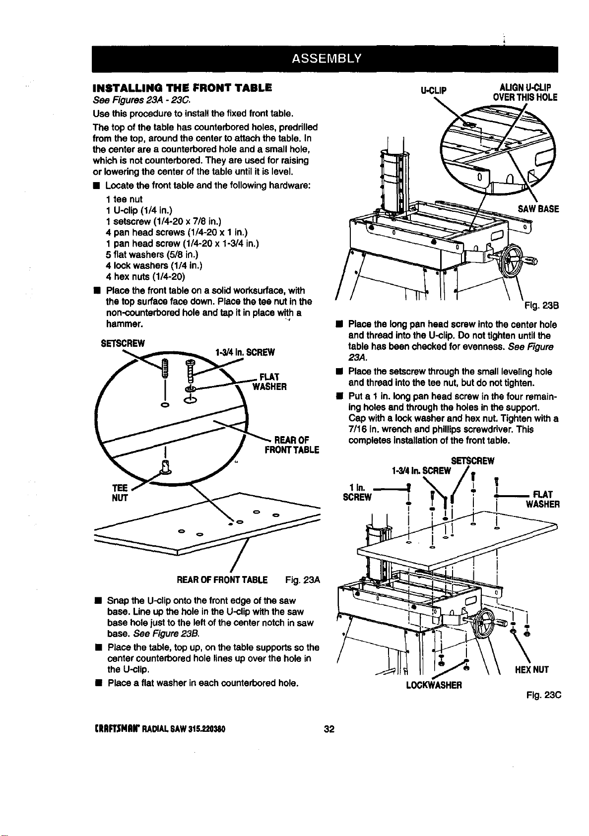
INSTALLING THE FRONT TABLE
See Figures23,4 - 23C.
Use thisprocedureto installthe fixed fronttable.
The top ofthe table hascounterboredholes, preddlled
from thetop, aroundthe center toattach the table. In
the center are a counterboredholeand a smallhole,
whichis not counterbored.They are used for raising
or loweringthe center of thetable until itislevel.
• Locate the fronttable and thefollowinghardware:
1 tee nut
1 U-clip (1/4 in.)
1 setscrew(1/4-20 x 7/8 in.)
4 pan head screws (1/4-20 x 1 in.)
1 pan head screw (1/4-20 x 1-3/4 in.)
5 fiatwashers (5/8 in.)
4 lockwashers (1/4 in.)
4 hex nuts(1/4-20)
• Placethe fronttable on a solidworksurfoce,with
the top surfaceface down. Placethe tee nutin the
non-counterboredhole andtap it inplace with•
hammer.
SETSCREW
1.3/4In.SCREW
FLAT
WASHER
TEE
NUT
REAROFFRONTTABLE Fig. 23A
• Snap the U-clipontothefrontedge ofthe saw
base. Lineup the hole inthe U-clipwiththe saw
base holejusttothe leftofthe center notchin saw
base. See Figure23B.
• Place the table, top up, onthe table supportssothe
center counterboredholelinesup over the holein
the U-clip.
• Placea flatwasher in eachcounterboredhole.
U-CLIP AUGNU-CLIP
OVERTHISHOLE
Fig, 23B
B Placethe longpan head screw intothe center hole
and threadintothe U-clip.Do nottightenuntilthe
table has been chockedfor evenness.See Figure
23,4.
• Placethe setscrewthroughthesmall levelinghole
end threadintothetee nut,butdo nottighten.
• Puta 1 in. longpan head screwin the fourremain-
ingholesend throughthe holesin the support.
Cap with• lockwasher end hexnut,Tightenwitha
7/16 in.wrenchand phillipsscrewdriver.This
completesinstallationofthe fronttable.
SETSCREW
1-3/4In.SCREW
l
SCREwlln"_1 ; ,I°_ FLAT
I I WASHER
LOCKWASHER
HEXNUT
Fig.23C
[ERFTSMRWRADIALSAW315.220380 32
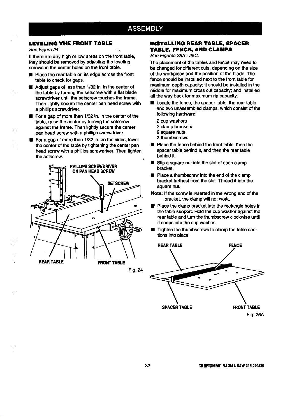
LEVELINGTHE FRONTTABLE
See Figure24.
Ifthere are any high or lowareas onthe fronttable,
they shouldbe removed byadjustingthe leveling
screwsin thecenter holeson thefronttable.
• Placethe rear table on itsedge acrossthe front
table to check for gaps.
• Adjust gaps of lessthan 1/32 in.in the center of
the table bytuming the setscrewwith a fiat blade
screwdriveruntilthe setscrewtouchestheframe.
Then lightlysecure the center pan head screwwith
a phillipsscrewdriver.
• Fora gap ofmore than 1/32 in.in thecenterof the
table, raisethe center byturningthe setscrew
againstthe frame. Then lightlysecurethe center
pan head screw witha phillipsscrewdriver.
• Fora gap ofmore than 1/32 in.on the sides,lower
the center ofthe table bytighteningthecenter pan
head screwwitha phillipsscrewdriver.Then tighten
thesetscrew.
INSTALLING REAR TABLE, SPACER
TABLE, FENCE, AND CLAMPS
See Figures25A - 25C.
The placementofthe tablesand fence may need to
be changed for differentcuts,dependingon the size
ofthe workpieceand the positionofthe blade.The
fence shouldbe installednextto the front table for
maximumdepthcapacity;it shouldbe installedinthe
middle for maximumcrosscut capacity;and installed
all the way backfor maximumripcapacity.
• Locatethe fence, the spacertable,the rear table,
and two unassembledclamps,whichconsistof the
following hardware:
2 cup washers
2 clamp brackets
2 square nuts
2 thumbscrews
• Placethe fence behindthe fronttable,then the
spacertable behindit, and thenthe reartable
behindit.
• Slipa squarenutintothe slotofeach clamp
PHILLIPSSCREWDRIVER bracket.
ONPANREADSCREW
_ll _% SETSCREW • Place a thumbscrewintothe end ofthe clamp
bracketfarthestfromthe slot.Thread it intothe
enut
Note: If thescrew isinsertedinthe wrongend ofthe
bracket,the clampwillnotwork.
• Placethe clampbracketintothe rectangleholesin
___ REARTABLE FENCEthe table support.Heldthe cupwasher against the
reartable and turnthethumbscrewclockwiseuntil
itsnaps intothecup washer,
• Tightenthe thumbscrewstoclampthe table sec-
tionsintoplace.
REARTABLE FRONTTABLE Fig 24
SPACERTABLE FRONTTABLE
Fig. 25A
33 [RRFTSNRWRADIALSAW315.220380
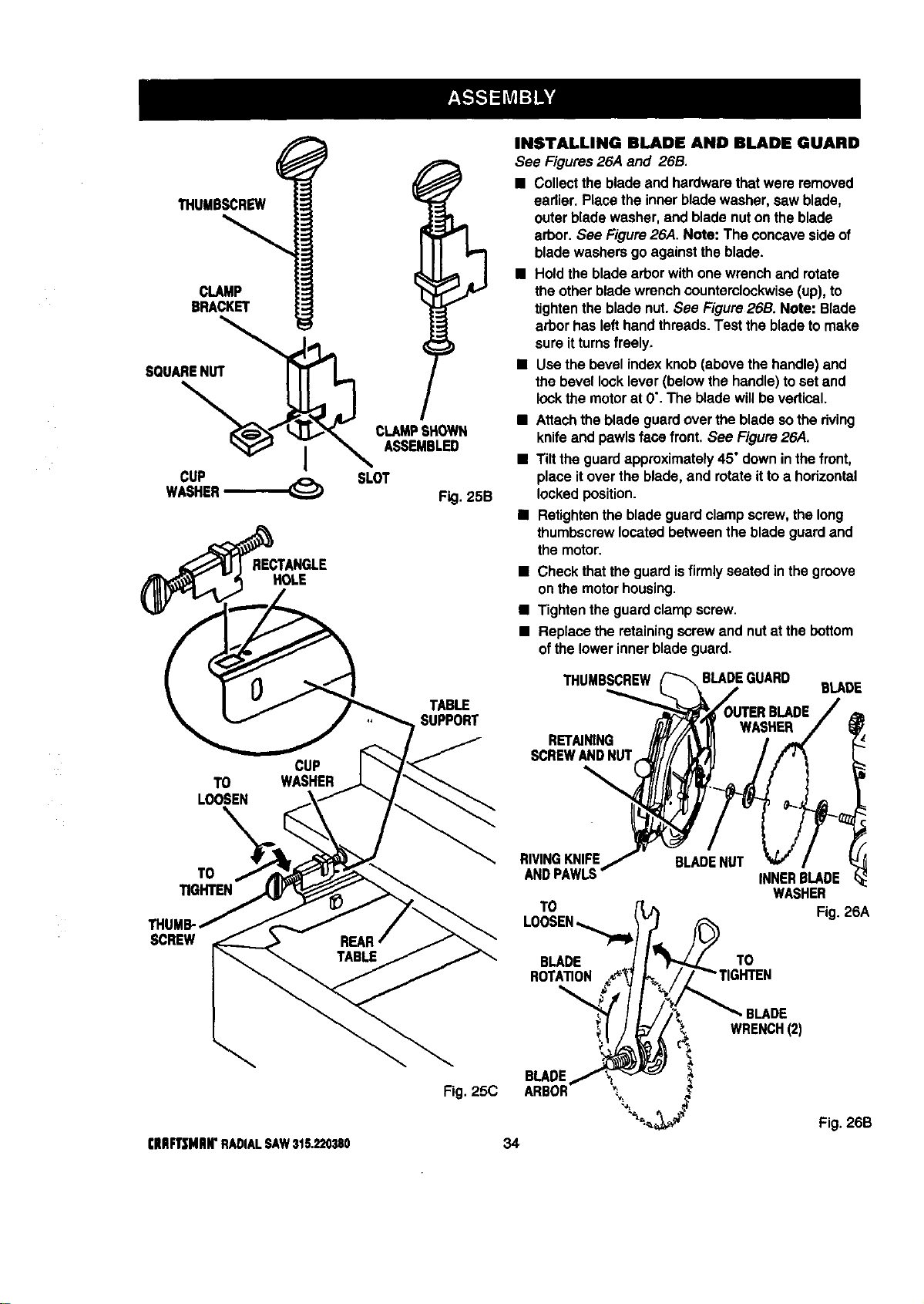
THUMBSCREW
CLAMP
BRACKET
SQUARENUT
I
CUP
WASHER
RECTANGLE
HOLE
CUP
TO WASHER
LOOSEN
TO
TIGHTEN
SCREW
(IIRFT|MIIW RADIAL SAW 315.220380
CLAMPSHOWN
ASSEMBLED
SLOT
F .25B
TABLE
SUPPORT
Fig. 25C
INSTALLING BLADE AND BLADE GUARD
See Figures26,4 and 26B.
• Collectthe bladeand hardwarethatwere removed
eadier. Placethe inner bladewasher,saw blade,
outerbladewasher,and blade nuton theblade
arbor. See Figure26A. Note: The concavesideof
bladewashersgo againstthe blade.
• Holdthe bladearborwithone wrenchand rotate
theotherbladewrenchcounterclockwise(up),to
tightenthe bladenut.See Figure26B. Note: Blade
arborhas lefthandthreads.Testthe bladetomake
sure itturnsfreely,
• Usethe bevel indexknob(abovethe handle)and
the bevel locklever(belowthe handle)to set and
lockthe motorat 0".The bladewillbevertical.
• Attachthe bladeguardover theblade sothe riving
knifeand pawlsface front. See Figure26A.
• Tiltthe guard approximately45°downinthe front,
place itover the blade, and rotateittoa horizontal
lockedposition.
• Retightanthe bladeguardclamp screw,thelong
thumbscrewlocatedbetweenthe bladeguardand
the motor.
• Check thatthe guardisfirmly seatedin the groove
onthe motorhousing.
• Tightentheguard clampscrew.
• Replacethe retainingscrewand nutat the bottom
ofthe lowerinnerbladeguard.
THUMBSCREW
BLADE
RET_NING
SCREWANDNUT
RIVINGKNIFE
ANDPAWLS
TO
BLADENUT
INNERBLADE
WASHER
Fig. 26A
BLADE
ROTATION
TO
34
BLADE
BLADE
WRENCH(2)
Fig. 26B
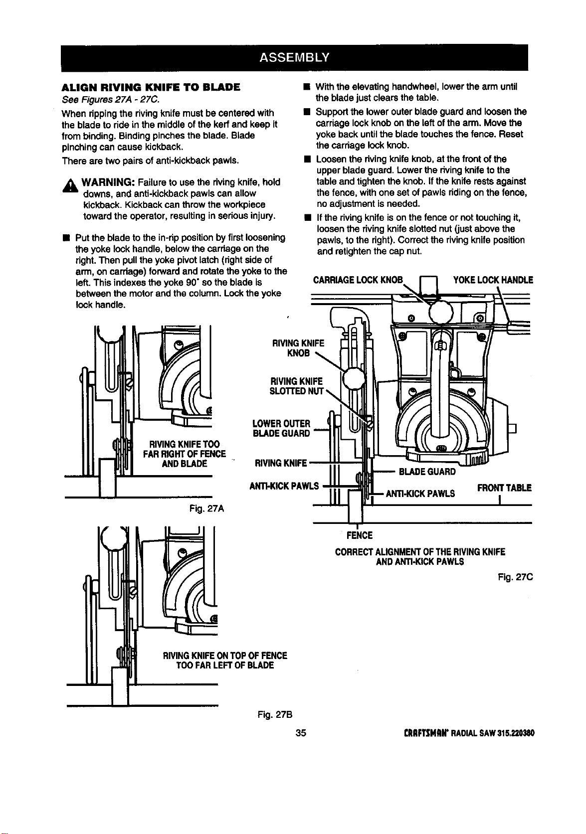
ALIGN RIVING KNIFE TO BLADE
See Figures27A - 27C.
When rippingthe rivingknife mustbe canteredwith
the blade to ridein the middleofthe kerfand keep it
from binding.Bindingpinchesthe blade. Blade
pinchingcan cause kickback.
There are two pairsofanti-kickbackpawls.
_l WARNING: Failureto usethe rivingknife,hold
downs, and anti-kickbackpawls can allow
kickback.Kickbackcan throwthe workpiece
towardthe operator, resultinginseriousinjury.
• Put the bladeto the in-rippositionbyfirstloosening
the yokelockhandle,belowthe carriageonthe
right.Then pulltheyokepivotlatch (rightside of
arm, on carriage) forwardand rotatetheyoketo the
left. This indexesthe yoke90°sothe blade is
betweenthe motorandthe column.Lockthe yoke
lockhandle.
• Withthe elevatinghandwheel,lowerthe arm until
the bladejustclearsthe table.
• Supportthe lowerouterbladeguardand loosenthe
carriagelockknobon the leftofthe arm. Move the
yokebackuntilthe bladetouchesthe fence. Reset
thecarriage lookknob.
• Loosenthe rivingknifeknob, at thefrontof the
upperblade guard.Lowerthe rivingknifetothe
table and tightenthe knob. ifthe kniferestsagainst
the fence,with one set ofpawls ridingonthe fence,
noadjustmentisneeded.
• Ifthe rivingknifeison thefence ornot touchingit,
loosenthe rivingknifeslottednut (justabove the
pawls,to the right).Correcttherivingknife position
and retightenthe cap nut.
CARRIAGELOCKKNOB
%
YOKELOCKHANDLE
m
( RIVINGKNIFETOO
FARRIGHTOFFENCE
ANDBLADE
Fig. 27A
RIVINGKNIFE
KNOB
RIVINGKNIFE
LOWEROUTER
BLADEGUARD
RIVINGKNIFE
ANTI-KICKPAWLS
BLADEGUARD
FRONTTABLE
I
FENCE
CORRECTALIGNMENTOFTHERIVINGKNIFE
ANDANTI-KICKPAWLS
Fig. 27C
RIVINGKNIFEONTOPOFFENCE
TOOFARLEFTOFBLADE
Fig. 27B
35 rlIIIFTSMRWRADIALSAW315,220380
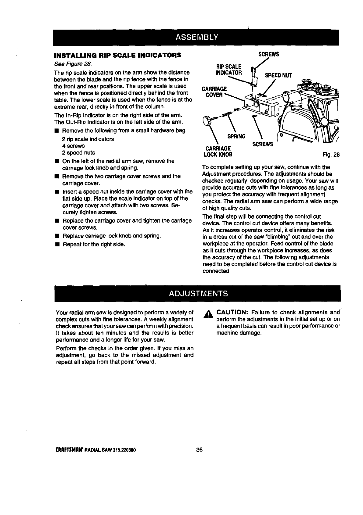
INSTALLING RIP SCALEINDICATORS
See Figure28.
The ripscale indicatorson the arm showthe distance
between the blade and the ripfence with thefence in
the frontand rear positions.The upperscale isused
when thefence is positioneddirectlybehindthe front
table. The lowerscale isused when the fenceis at the
extreme rear,directly infrontofthe column.
The In-Rip Indicatorison the dghtside ofthe arm.
The Out-Rip Indicatorison the leftsideof the arm.
• Remove the followingfroma smallhardware bag.
2 ripscale indicators
4 screws
2 speed nuts
• On the left ofthe radialarm saw, removethe
carriage lockknoband spdng.
• Remove the two carriage cover screwsandthe
carriagecover.
• Inserta speed nut insidethecarriage cover withthe
fiat sideup. Place thescale indicatoron topofthe
cardage coverand attachwith two screws. Se-
curelytightenscrews.
• Replacethe cardage cover and tightenthe carriage
coverscrews.
• Replace carriage lockknoband spring.
• Repeat for the right side.
RIPSCALE
INDICATOR
CARRIAGE
SCREWS
SPEEDNUT
_'_SPRING
CARRIAGE
LOCKKNOB
SCREWS
Fig.28
To complete settingup yoursaw, continue withthe
Adjustmentprocedures. The adjustmentsshouldbe
checked regulady,dependingon usage.Your saw will
provideaccurate cutswithfine tolerancesas long as
you protectthe accuracywithfrequentalignment
checks.The radialarm saw can performa wide range
of highqualitycuts.
The finalstepwillbe connecting the controlcut
device. The controlcutdevice offersmany benefits.
Asit increasesoperatorcontrol, iteliminatesthe risk
ina crosscutof the saw "climbing" Outand overthe
workpieceat the operator.Feed controlof the blade
as it cutsthroughthe workpieceincreases,as does
theaccuracy ofthe cut.The followingadjustments
need to be completedbeforethe controlcutdevice is
connected.
Your radialarm saw isdesignedto performa varietyof
complex cutswithfine tolerances.A weeklyalignment
checkensuresthatyoursawcanperformwithprecision.
It takes about ten minutes and the results is better
performanceand a longerlifefor yoursaw.
Performthe checksin the order given. If you missan
adjustment, go back to the missed adjustment and
repeat all steps from that pointforward.
_k CAUTION: Failure to check alignments and_
performthe adjustmentsin the initialset up or on
a frequentbasiscan resultinpoorperformanceor
machinedamage.
CRIIFTSHAM'RADIALSAW315.220380 36
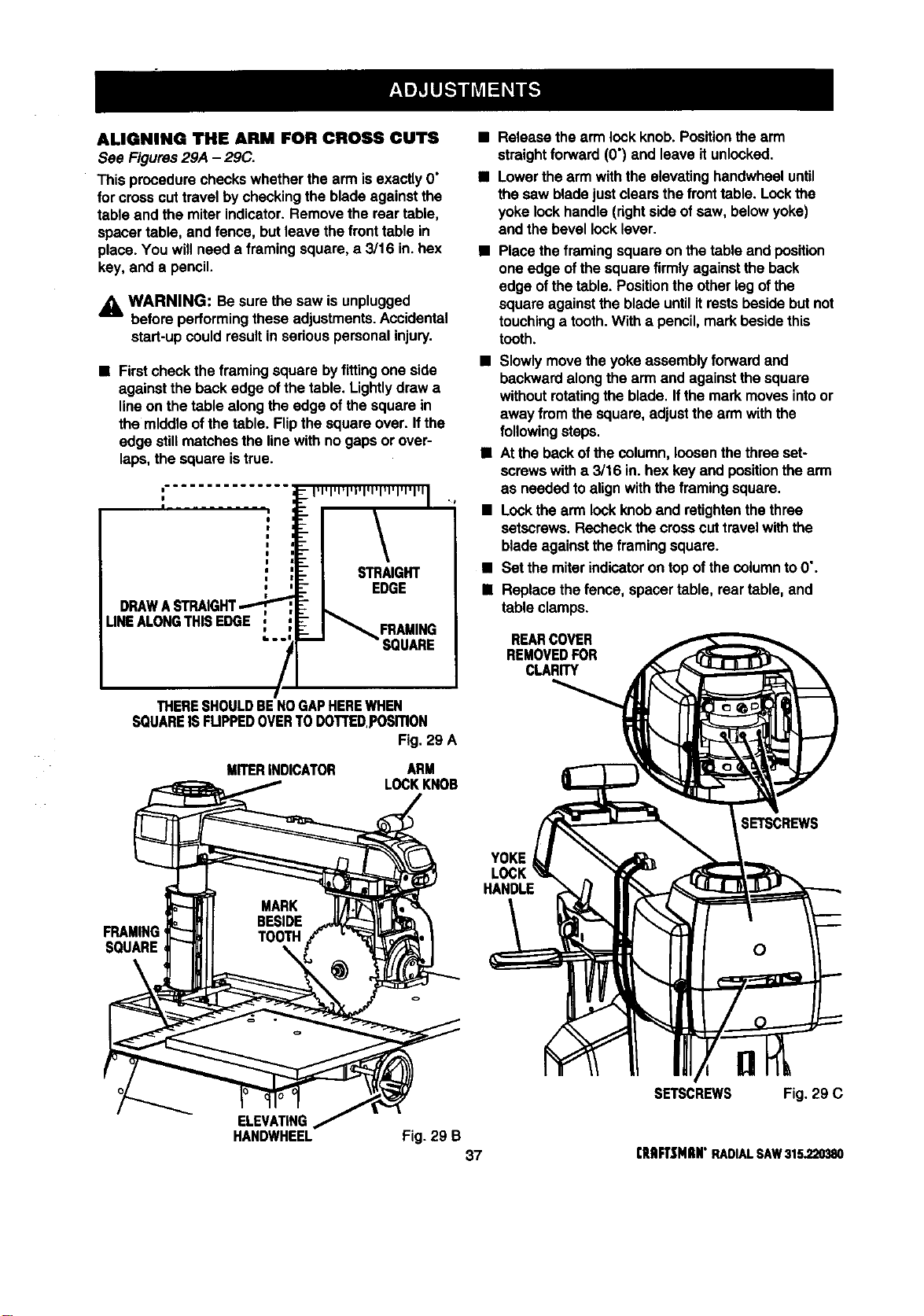
ALIGNING THE ARM FOR CROSS CUTS
See Figures29A - 29C.
This procedurecheckswhetherthe arm isexactlyO"
for crosscuttravel by checkingtheblade againstthe
table and the miter indicator.Remove the rear table,
spacertable, and fence, but leavethe fronttable in
place. You willneed a framingsquare, a 3/16 in. hex
key, and a pencil.
_lb WARNING: Besure the saw isunplugged
before performingthese adjustments.Accidental
start-upcould resultin seriouspersonalinjury.
• Firstcheckthe framingsquare byfittingone side
againstthe backedge ofthe table. Lightlydrew a
lineon the table alongthe edge of the squarein
the middle ofthetable. Flipthe squareover. If the
edge stillmatchesthe linewith no gaps or over-
laps,the square istrue.
DRAWASTRAIGHT..."-
UNEALONGTHISEDGE
FRAMING
SQUARE
THERESHOULDBENOGAPHEREWHEN
SQUAREISFUPPEDOVERTODOTTED,posmoN
Fig. 29 A
MITERINDICATOR ARM
LOCKKNOB
Release the arm lock knob.Positionthearm
straightforward (O') and leaveit unlocked.
Lowerthe arm withthe elevatinghandwheeluntil
the saw bladejust clearsthe front table. Lockthe
yokelockhandle (rightside of saw, belowyoke)
and the bevel locklever.
• Place theframingsquareon thetable and position
one edge of thesquarefirmlyagainstthe back
edge of the table. Positionthe otherleg ofthe
squareagainstthe bladeuntilitrestsbesidebutnot
touchinga tooth.Witha pencil,markbesidethis
tooth.
• Slowlymovethe yokeassemblyforwardand
backwardalongthe arm and againstthe square
withoutrotatingthe blade. Ifthe markmovesintoor
away fromthe square,adjustthe arm withthe
followingsteps.
• Atthe backofthe column,loosenthe three set-
screwswith a 3/16 in.hex keyand positionthe arm
as neededto alignwiththe framingsquare.
• Lockthe arm lockknoband retightenthethree
setscrews. Recheckthecrossouttravelwith the
bladeagainstthe framingsquare.
• Set the miterindicatoron topof thecolumnto 0".
• Replace thefence, spacertable, rear table, and
table clamps.
REARCOVER
REMOVEDFOR
CLARITY
YOKE
HANDLE
SETSCREWS
FRAMING
SQUARE
ELEVATING
HANDWHEEL
Fig. 29 B
37
SETSCREWS Fig. 29 C
rRIIFTtNIIN"RADIALSAW315,220380
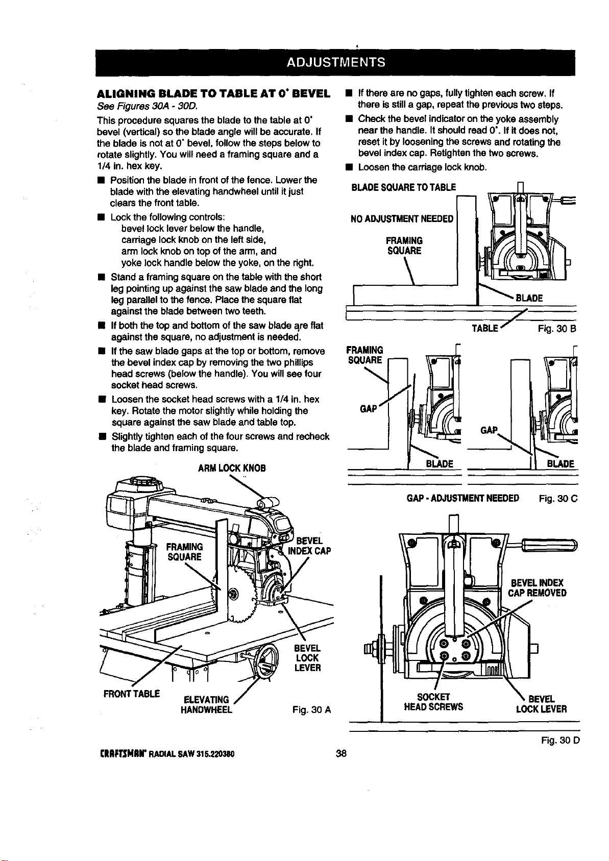
ALIGNING BLADE TO TABLE AT O" BEVEL
See Figures 30A - 30D.
This proceduresquaresthe blade tothe table at O"
bevel (vertical)sothe blade angle willbe accurate. If
the blade is not at D"bevel,followthe stepsbelowto
rotate slightly.You willneed a framing squareand a
1/4 in.hex key.
• Positiontheblade infrontofthefence. Lowerthe
bladewiththe elevatinghandwheeluntilitjust
clearsthe fronttable.
• Lockthe followingcontrols:
bevel locklever belowthe handle,
carriagelockknobon the leftside,
arm lock knobontop ofthe arm, and
yoke lockhandle belowtheyoke, on the dght.
• Stand a framing squareon thetable withthe short
leg pointingup againstthe saw bladeand the long
leg parallelto thefence. Place the squareflat
againstthe bladebetween two teeth.
• Ifboththe topand bottomofthe saw blade a_reflat
againstthe square, no adjustment isneeded.
• Ifthe saw bladegaps at the top or bottom,remove
thebevel indexcap by removingthe two phillips
head screws(belowthe handle).You willsee four
sockethead screws.
• Loosenthe sockethead screwswith a 1/4 in.hex
key. Rotate the motorslightlywhileholdingthe
square againstthe saw bladeand table top.
• Slightlytighteneachofthe fourscrews and recheck
the bladeand framing square.
ARMLOCKKNOB
• Ifthere are no gaps,fullytighteneach screw, If
there isstilla gap, repeatthe previoustwosteps.
• Checkthe bevel indicatoron the yokeassembly
near the handle.ItshouldreadO'. If itdoes not,
resetitby looseningthe screwsand rotatingthe
bevel indexcap. Retightenthe twoscrews.
• Loosenthecardagelockknob.
BLADESQUARETOTABLE
NO ADJUSTMENTNEEDED
FRAMING
SQUARE
FRAMING
SQUARE
BLADE
TABLEj Fig. 30 B
GAP
BLADE
FRONTTABLE
INDEXCAP
BEVEL
LOCK
LEVER
ELEVATING
HANDWHEEL Fig. 30 A
GAP-ADJUSTMENTNEEDED Fig. 30 C
SOCKET
HEADSCREWS
BEVELINDEX
CAPREMOVED
f
_.BEVEL
LOCKLEVER
Fig. 30 D
CRAFTSMIIH"RADIALSAW315.220380 38
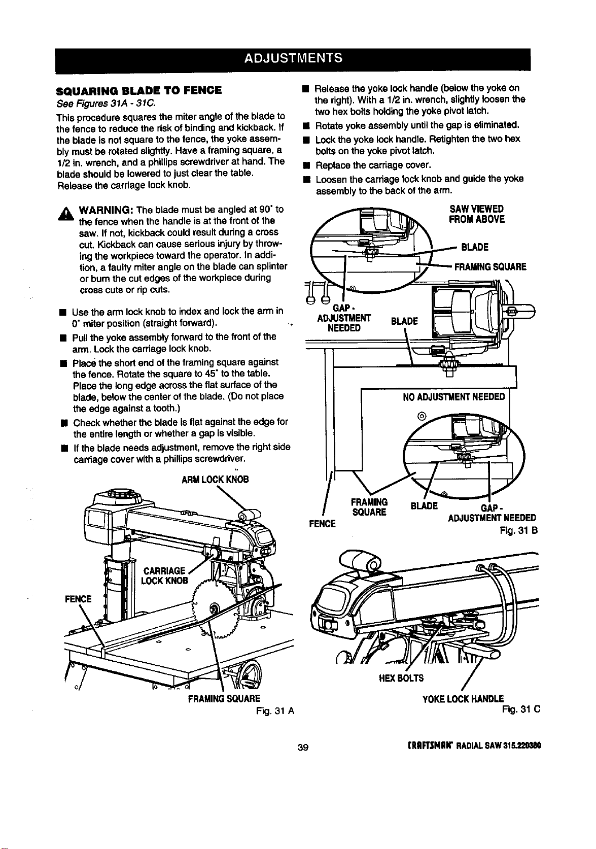
SQUARINGBLADETO FENCE
See Figures31A - 31C.
Thisproceduresquaresthe miterangleof the bladeto
the fenceto reducethe dskofbindingand kickback.If
the blade isnot squareto thefence, theyoke assem-
blymustbe rotatedslightly.Have a framing square,a
1/2 in.wrench, and a phillipsscrewdriverat hand.The
blade shouldbe loweredto justclear the table.
Release the carriage lockknob.
_k WARNING: The blademustbe angled at 90"to
the fence when the handle isat the frontof the
saw. If not,kickbackcould resultduringa cross
cut. Kickbackcan causeseriousinjuryby throw-
ingthe workpiecetowardtheoperator. In addi-
tion, a faulty miterangle on the bladecan splinter
or bum the cutedges ofthe workpiecedudng
cross cutsor dp cuts.
• Usethe arm lock knobto indexand lockthe arm in
0" miterposition(straightforward). .,
• Pullthe yoke assemblyforward tothe front ofthe
arm. Lockthe carriage lockknob.
• Placethe shortend ofthe framing squareagainst
the fence. Rotate thesquareto45°to thetable.
Placethe longedge acrosstheflat surfaceofthe
blade, belowthe center oftheblade. (Do notplace
theedge againsta tooth.)
• Check whetherthe blade isflat againsttheedge for
the entirelengthor whethera gap isvisible.
• Ifthe bladeneeds adjustment,removethe rightside
carriage coverwitha phillipsscrewddver.
ARMLOCKKNOB
FENCE
FRAMINGSQUARE
Fig. 31 A
• Release theyoke lock handle(belowtheyoke on
the fight).With a 1/2 in.wrench,slightlyloosenthe
twohex boltsholdingtheyoke pivotlatch.
• Rotateyoke assembly untilthe gap iseliminated.
• Locktheyoke lockhandle.Retightenthetwo hex
boltson the yokepivotlatch.
• Replace thecarriagecover.
• Loosenthe carriagelockknoband guidethe yoke
assemblyto theback ofthe arm.
SAWVIEWED
FROMABOVE
BLADE
GAP-
ADJUSTMENT BLADE
NEEDED
I NOADJUSTMENTNEEDEDI
FRAMING BLADE GAP-
SQUARE
ADJUSTMENTNEEDED
FENCE
Fig. 31 B
HEXBOLTS
YOKELOCKHANDLE
Fig. 31 C
39 (RRFT|MRW RADIALSAW$1S_20380
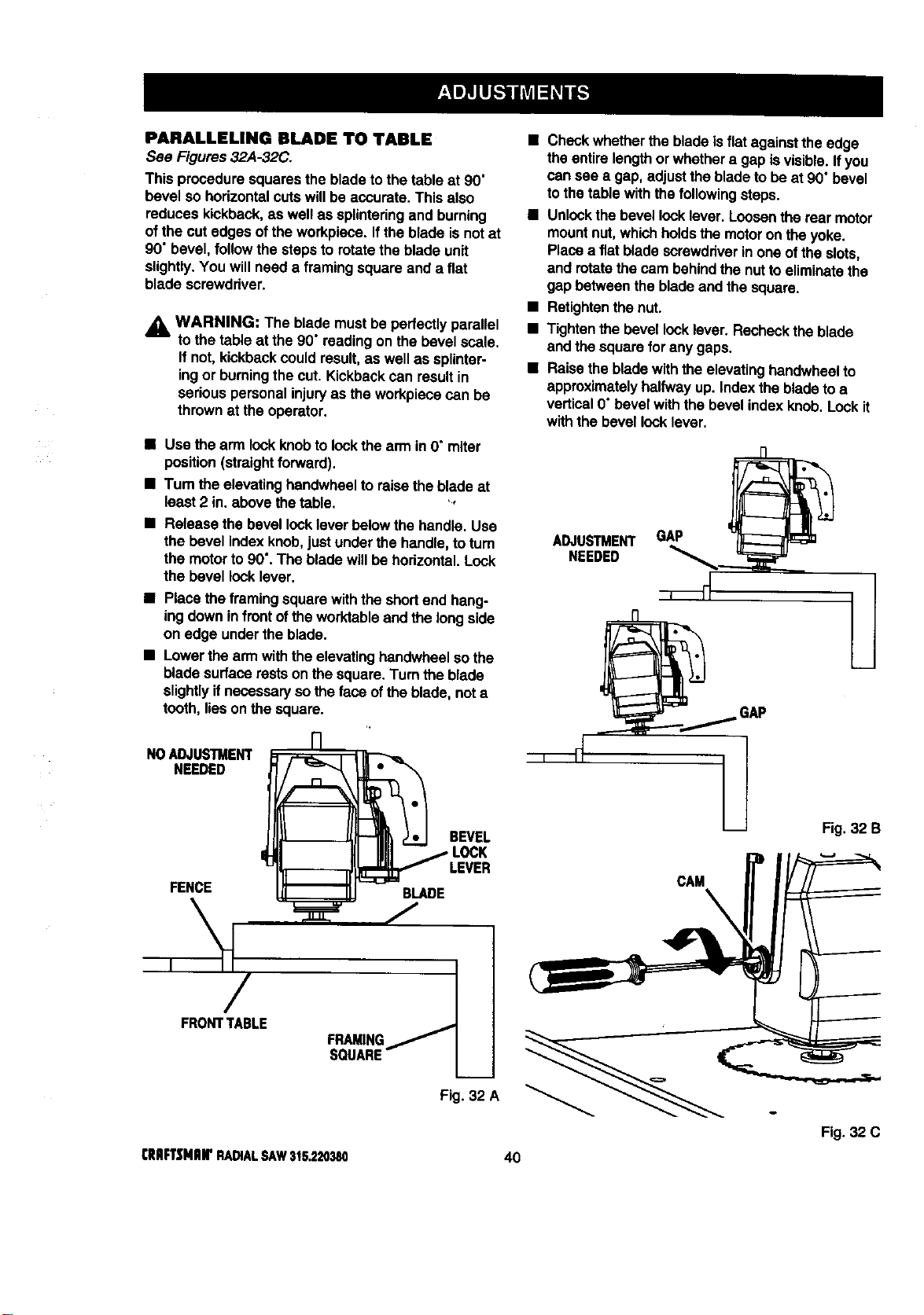
PARALLELING BLADE TO TABLE
See Figures32A-32C.
This proceduresquaresthe bladeto thetable at 90"
bevel sohodzontatcutswillbe accurate.Thisalso
reduceskickback,as well as splintedngand burning
ofthe cutedges of the workpiece.Ifthe blade isnot at
90' bevel,followthe stepsto rotatethe blade unit
slightly.You willneed a framingsquareand a flat
blade screwdriver.
,_ WARN|NG: The blade must be pedactlyparallel
to thetable at the 90"readingon the bevel scale.
Ifnot, kickbackcould result,as well as splinter-
ingor burningthe cut. Kickbackcan resultin
seriouspersonalinjuryas the workpiecacan be
thrownat the operator.
• Check whetherthe bladeis flat againstthe edge
theentire length or whethera gap is visible.Ifyou
cansee a gap, adjustthe blade tobe at 90" bevel
tothe table withthe followingsteps.
• Unlockthe bevellock lever.Loosenthe rear motor
mountnut,whichholdsthe motoron the yoke.
Placea fiat bladescrewdriverin one ofthe slots,
and rotatethe cam behindthe nuttoeliminatethe
gap betweenthe bladeand thesquare.
• Retightenthe nut.
• Tightenthebevel rockfever. Recheckthe blade
and the square for anygaps.
• Raise the bladewith theelevatinghandwheelto
approximatelyhalfwayup. Indexthebladeto a
vertical0"bevel withthe bevel indexknob. Lockit
withthe bevel locklever.
• Use the arm lock knobto lockthe armin O"miter
position(straightforward).
• Turn the elevatinghandwheelto raisethe bladeat
least 2 in. above thetable. ',
Release the bevel locklever belowthe handle. Use
the bevel indexknob,just underthe handle,toturn
the motorto 90".The blade willbe hodzontal.Lock
the bevel locklever.
• Place theframingsquarewiththe shortend hang-
ingdowninfront oftheworktableand the longside
on edge underthe blade.
• Lowerthe armwiththe elevatinghandwheelso the
bladesurface restson the square.Turn the blade
slightlyifnecessaryso the face ofthe blade, not a
tooth, tieson the square.
NOADJUSTMENT
NEEDED
FENCE BLADE
BEVEL
LOCK
FRONTTABLE
FRAMING
SQUARE
Fig. 32 A
ADJUSTMENT GAP
NEEDED
Fig.32 B
o
Fig. 32 C
CRIIFTSNIIIrRADIALSAW315,220380 40
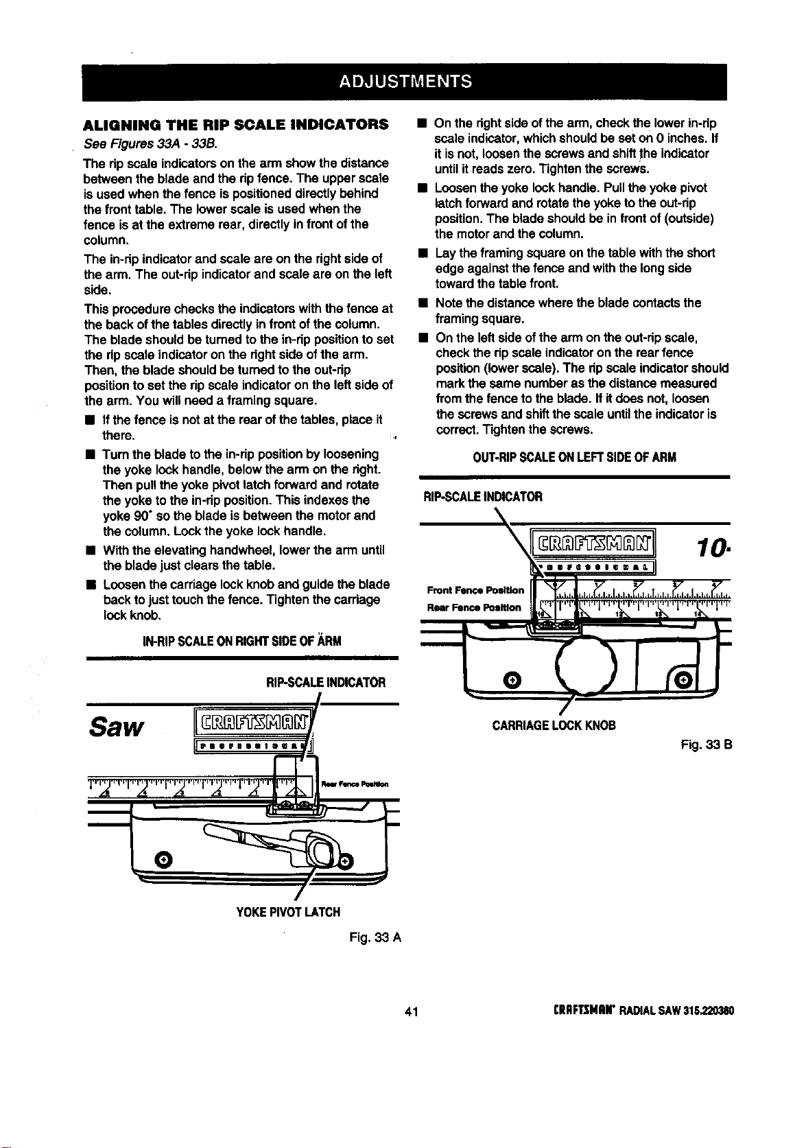
ALIGNING THE RIP SCAL• INDICATORS
See Figures33A - 33B.
The ripscale indicatorson the arm showthe distance
between the bladeand the ripfence. The upperscale
isused when the fence ispositioneddirectlybehind
the front table.The lowerscaleis used when the
fence isat the extreme roar, directlyinfrontofthe
column.
The in-ripindicatorand scale are on the rightside of
the arm. The out-ripindicatorand scale are on the left
side.
This procedurechecksthe indicatorswith thefence at
the backof the tables directlyin front ofthe column.
The blade shouldbe turnedto the in-dp positionto set
the ripscale indicatoron the dghtside ofthe arm.
Then, the bladeshouldbe turnedto the out-dp
positionto set the ripscale indicatoron the leftside of
the arm. You willneed a framingsquare.
• If thefence is notat the rear ofthe tables,place it
there.
• Turn the blade tothe in-rippositionby loosening
the yoke lock handle,belowthe arm on the right.
Then pullthe yoke pivotlatchforward and rotate
the yoke tothe in-ripposition.This indexesthe
yoke 90" sothe blade isbetween the motorand
the column.Locktheyoke lock handle.
• Withthe elevating handwheel, lowerthe arm until
the bladejust clears thetable.
• Loosenthe carriage lock knoband guidethe blade
beck to justtouchthe fence. Tightenthe carriage
lock knob.
IN-RIPSCALEONRIGHTSlOEOF_,RM
RIP-SCALEINDICATOR
Saw II
11,,, °,,,,,,,,
•
.,d! A ,_ .d! .__
• On the rightside ofthe arm, checkthe lowerin-dp
scale indicator,whichshouldbe seton O inches.If
itisnot, loosenthe screws and shiftthe indicator
untilit reads zero. Tightenthe screws.
• Loosenthe yoke lockhandle.Pulltheyoke pivot
latchforward and rotatethe yoketothe out-rip
position.The bladeshouldbe in front of(outside)
the motorand the column.
• Laythe framingsquareon thetable withthe short
edge againstthefence and withthe long side
towardthetable front.
Note the distancewhere the bladecontactsthe
framingsquare.
On the leftside ofthearm on theout-dpscale,
checkthe ripscaleindicatoron the rearfence
position(lowerscale). The ripscaleindicatorshould
markthe same numberas the distancemeasured
from thefence tothe blade. If itdoes not, loosen
thescrewsand shiftthe scale untilthe indicatoris
correct.Tightenthe screws.
OUT-RIPSCALEONLEFTSIDEOFARM
RIP.SCALEINDICATOR
Front Fence Position
Rear Fence Position
10.
,,,..,°=.,11
CARRIAGELOCKKNOB
Fig. 33 B
YOKEPIVOTLATCH
Fig. 33 A
41 [IIliFTtMitN" RADIALSAW315.220380
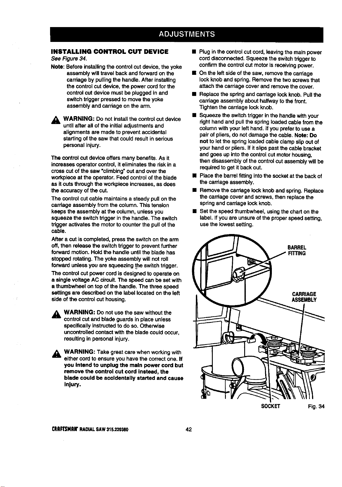
INSTALLING CONTROL CUT DEVICE
See Figure34.
Note: Before installingthe controlcutdevice,the yoke
assemblywilltravel beck and forwardon the
carriage by pullingthe handle. Afterinstalling
the control cutdevice, the powercordfor the
control cut device mustbe pluggedinand
switchtriggerpressedtomove theyoke
assemblyand carriage on the arm.
,_= WARNING: Do notinstallthecontrolcut device
untilafter all ofthe initialadjustmentsand
alignmentsare made to preventaccidental
startingof thesaw thatcouldresultin serious
personalinjury.
The controlcut deviceoffers manybenefits.As it
increasesoperatorcontrol, iteliminatesthe riskin a
crosscutofthe saw "climbing"out and over the
workpieceat the operator. Feed controlofthe blade
as it cutsthroughthe workpieceincreases,as does
the accuracyofthe cut.
The controlcutcable maintainsa steadypullon the
cardage assemblyfromthe column.This tension
keepsthe assemblyat the column,unlessyou
squeeze the switchtriggerin the handle.The switch
tdgger activatesthe motorto counter the pullofthe
cable.
After a cut iscompleted,pressthe switchon thearm
off, then release the switchtdggerto preventfurther
forward motion.Hold the handle untilthe blade has
stopped rotating.The yokeassemblywill notroll
forward unlessyou are squeezing_e switchtrigger.
The controlcut powercord isdesignedto operateon
a singlevoltageAC circuit.The speed can be set with
a thumbwheelontop of the handle.The three speed
settingsare describedon the label locatedon the left
side of the control cut housing.
WARNING: Do notuse the saw withoutthe
controlcutand blade guardsin place unless
specificallyinstructedto do so. Otherwise
uncontrolledcontactwith the bladecouldoccur,
resultingin personalinjury.
,_ WARNING: Take great care when workingwith
eithercordto ensureyou havethe correctone. If
you Intend to unplug the main power cord but
remove the control cut cord Instead, the
blade could be accidentally started and cause
Injury.
• Plugin thecontrol cutcord,leavingthe mainpower
corddisconnected.Squeeze the switchtdggerto
confirmthecontrol cut motorisreceivingpower.
• On the leftsideofthe saw, removethe carriage
lockknoband spring.Remove thetwoscrewsthat
attachthecarriage coverand removethe cover.
• Replacethespdngand carriage lockknob.Pullthe
cardage assemblyabouthalfwayt0 the front.
Tightenthe carriage lockknob.
• Squeezethe switchtriggerinthe handlewithyour
dght hand and pullthe springloadedcable from the
columnwithyourlefthand. Ifyou preferto usea
pairofpliers,do not damage thecable. Note: Do
not toletthe spdngloadedcable clampslipout of
yourhand or pliers.If itslipspastthecable bracket
and goes up intothecontrol cutmotorhousing,
then disassemblyofthe controlcutassemblywillbe
requiredto get itbeck out.
• Place thebarrelfittingintothe socketat the backof
thecarriageassembly.
• Remove the carriage lockknoband spring.Replace
thecardage cover and screws,then replacethe
springand carriagelockknob.
• Set thespeed thumhwheel,usingthecharton the
label. Ifyouare unsureofthe properspeed setting,
use thelowestsetting.
BARREL
FIITING
CARRIAGE
ASSEMBLY
SOCKET Fig. 34
CIIAFrSHlUFRADIALSAW315.220380 42
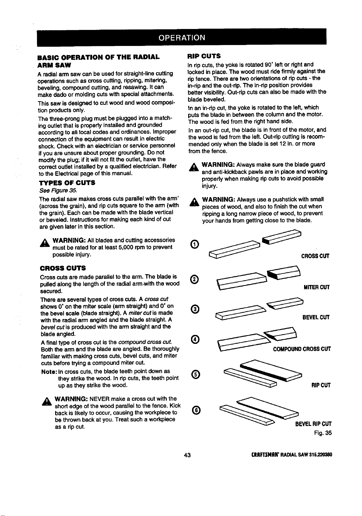
BASIC OPERATION OF THE RADIAL
ARM SAW
A radialarm saw can be usedfor straight-linecutting
operationssuch as cross cutting,ripping,mitering,
beveling,compoundcutting,and resawing.Itcan
make dado or moldingcutswithspecialattachments.
This sew isdesignedto cutwoodand woodcomposi-
tionproductsonly.
The three-prongplug mustbe pluggedintoa match-
ingoutletthat is properlyinstalledand grounded
accordingto all localcodes and ordinances.Improper
connectionofthe equipmentcan resultin electric
shook.Check with an electricianor service personnel
ifyou are unsureabout propergrounding.Do not
modifythe plug;ifitwill notfit the outlet,have the
correctoutletinstalledby a qualified electrician.Refer
tothe Electricalpage ofthis manual.
TYPES OF CUTS
See Figure35.
The radial sew makes crosscutsparallelwiththe arm'
(acrossthe grain),and ripcutssquaretothe arm (with
the grain). Each can be made withthe blade vertical
or beveled. Instructionsfor makingeach kindofcut
are givenlater inthis section.
A WARNING: All bladesand cuttingaccessories
am,
mustbe ratedfor at least5,000 rpmto prevent
possibleinjury.
CROSSCUTS
Crosscutsare made parallelto the arm. The blade is
pulledalong the length ofthe radialarm ,withthe wood
secured.
There are severaltypes ofcross cuts.A crosscut
shows 0"on the miterscale (arm straight)and 0"on
the bevel scale (blade straight).A mitercutis made
with the radial armangled and the blade straight.A
bevel cutis producedwiththe arm straightand the
blade angled.
A final type of crosscut isthe compound crosscut.
Boththe arm and the blade are angled. Bethoroughly
familiar with makingcresscuts, bevel cuts, and miter
cuts beforetryinga compoundmitercut.
Note: incross cuts,the blade teeth pointdownas
they strikethe wood. In ripcuts, theteeth point
up as they strikethe wood.
_ WARNING: NEVER make a cross cutwiththe
shortedge ofthe woodparallelto thefence. Kick
backis likelyto occur,causing the workpieceto
be thrownbackat you.Treat such a workpiece
as a ripcut.
RIP CUTS
In dpcuts, the yoke isrotated90" leftor rightand
lockedin place.The wood mustridefirmlyagainstthe
ripfence. There are twoorientationsof ripcuts- the
in-ripand the out-rip.The in-rippositionprovides
better visibility.Out-ripcutscan also be made withthe
bladebeveled.
In an in-ripcut, theyoke is rotatedto the left,which
putsthe blade in between the columnand the motor.
The woodisfed from the righthandside.
In an out-ripcut, the blade isin front ofthe motor,and
the wood isfed from the left.Out-rip cuttingis recom-
mendedonlywhen the blade isset 12 in.or more
fromthe fence.
_1= WARNING: Alwaysmake surethe blade guard
and anti-kickbackpawlsare in place and working
propedywhen making ripcutsto avoidpossible
injury.
WARNING: Always usea pushstickwith small
pieces ofwood, and alsotofinishthe cutwhen
rippinga long narrowpiece ofwood, to prevent
yourhandsfrom gettingcloseto the blade.
0 _ _CROSS cu'r
®
MITERcur
(_) _'_BEVEL CUT
COMPOUNDCROSSCUT
O __ RIPCUT
O ___BEVEL RIPCUT
Fig. 35
43 I:IIRFTSMflN"RADIALSAW315,220380
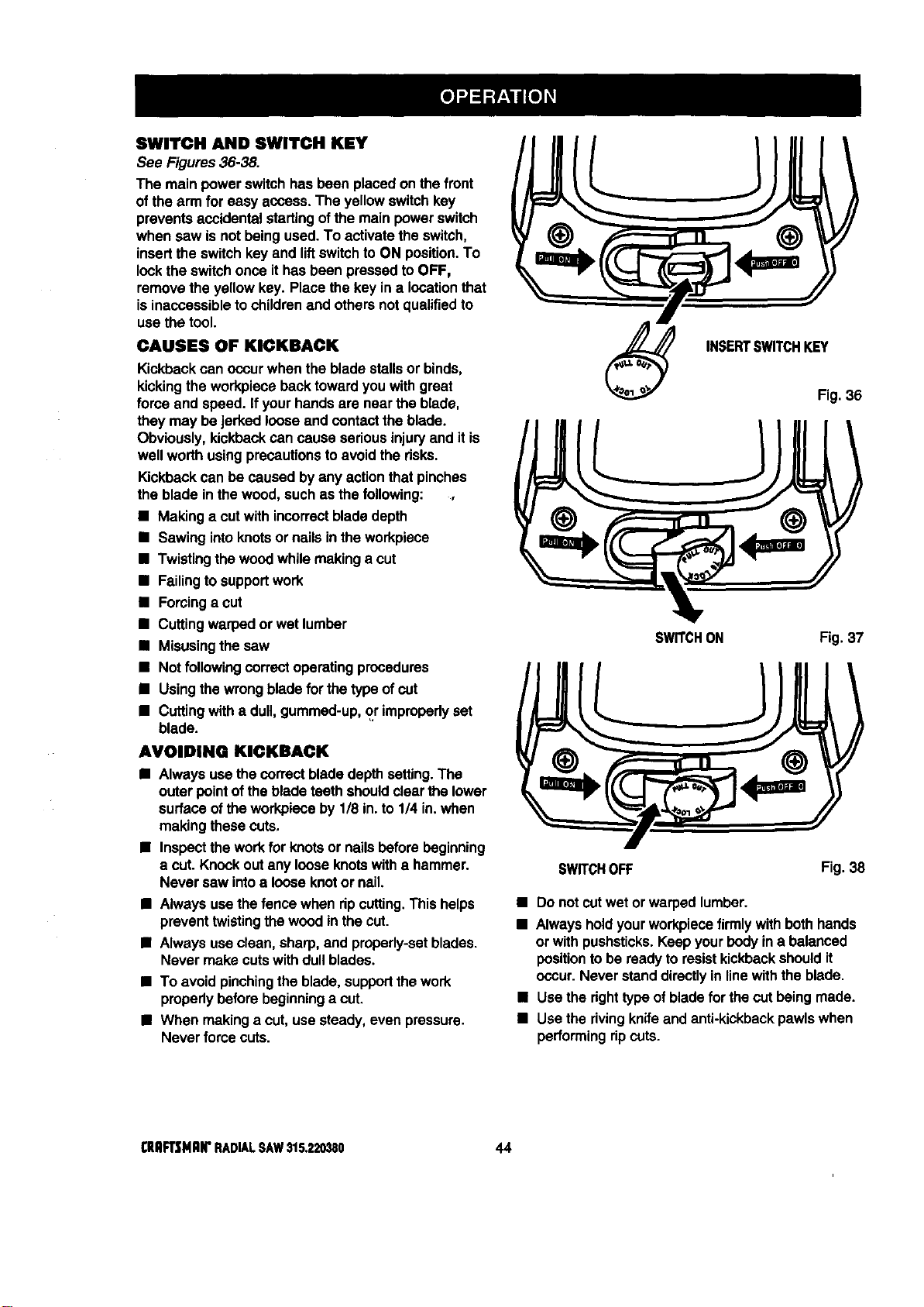
SWITCH AND SWITCH KEY
See Figures36-38.
The main power switchhasbeen placedon thefront
of the arm for easy access.The yellowswitchkey
preventsaccidental startingofthe main powerswitch
when saw is not beingused.To activate theswitch,
insertthe switchkey and liftswitchto ON position.To
lookthe switchonce ithas been pressedto OFF,
remove theyellow key. Placethe key in a locationthat
isinaccessibleto childrenend othersnot qualifiedto
use the tool.
CAUSES OF KICKBACK
Kickbackcan occurwhen the bladestallsor binds,
kickingthe workpiece backtowardyouwithgreat
force and speed. Ifyourhandsare near the blade,
they may be jerked looseand contactthe blade.
Obviously,kickbackcan cause seriousinjuryand it is
well worthusing precautionsto avoidthe risks.
Kickbackcan be caused byany actionthat pinches
the blade in thewood, such as the following:
• Making a cutwithincorrectbladedepth
• Sawingintoknotsor nailsinthe workpiece
• Twistingthe woodwhile makinga cut
• Failingto supportwork
• Forcinga cut
• Cuttingwarpedor wet lumber
• Misusingthe saw
• Not following correctoperatingprocedures
• Usingthe wrongbladefor the typeof cut
• Cuttingwitha dull,gummed-up,or improperlyset
blade.
AVOIDING KICKBACK
• Always usethe correctbladedepthsetting.The
outerpoint ofthe bladeteethshouldclear the lower
surface oftheworkpieceby 1/8 in.to 114in.when
makingthesecuts,
• Inspectthe workfor knotsor nailsbeforebeginning
a cut. Knockoutany looseknotswitha hammer.
Never saw intoa looseknotor nail.
• Always usethefence when ripcutting.Thishelps
preventtwistingthe woodinthe cut.
• Alwaysuse clean,sharp,and properly-setblades.
Never make cutswithdullblades.
• To avoidpinchingthe blade, supportthe work
properlybeforebeginninga cut.
• When makinga cut, usesteady,even pressure.
Never force cuts.
INSERTSWITCHKEY
Fig. 36
SWITCHON Fig. 37
SWITCHOFF Fig. 38
• Do not cutwet or warped lumber.
• Always holdyourworkpiecefirmlywithbothhands
or with pushsticks.Keep yourbodyina balanced
positionto be readyto resistkickbackshouldit
occur.Never standdirectlyinlinewiththe blade,
• Usethe right typeof bladeforthe cutbeing made.
• Use the rivingknifeand anti-kickbackpawlswhen
performingripcuts.
_EAFTSNlUI"RADIALSAW$15,220380 44
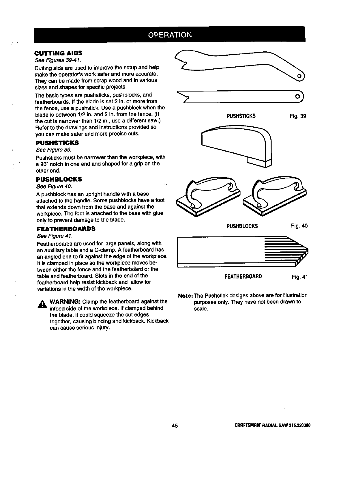
CUTTING AIDS
See Figures39-41.
Cuttingaids are usedto improvethe setup and help
make the operator'sworksafer end more accurate.
They can be made fromscrap woodand invarious
sizes and shapes forspecificprojects,
The basic typesare pushsticks,pushblocks,and
featherboards.If the blade isset 2 in. or morefrom
the fence, use a pushstick.Use a pushblockwhen the
blade isbetween 1/2 in. and 2 in.from the fence. (If
the cutisnarrowerthan 1/2 in., usea differentsaw.)
Refer to the drawingsand instructionsprovidedso
you san make saferand more precisecuts.
PUSHSTICKS
See Figure39.
Pushsticksmustbe narrowerthan theworkpiece,with
a 90"notchin one end and shapedfor a gripon the
otherend.
PUSHSTICKS Fig. 39
posLoo s
See Figure40.
A pushblockhas an uprighthandle with a base
attachedtothe handle. Some pushblockshavea foot
thatextends downfromthe base and againstthe
workpiece.The foot isattached to the basewith glue
onlytoprevent damage tothe blade.
FEATHERBOARDS
See Figure41.
Featherboardsare used for largepanels, along with
an auxiliary table and a C-clamp. A featharboardhas
an angled end to fitagainstthe edge of theworkplace.
It isclamped in place sothe workpiecemoves be-
tween eitherthe fence and the featherb6hrdor the
table and featherboard. Slotsin the end of the
faatharboardhelp resist kickbackand allowfor
variationsinthe widthofthe workplace.
_1= WARNING: Clamp the featherboardagainstthe
infeedside of theworkpiece. Ifclamped behind
the blade, itcouldsqueeze the cutedges
together,causing bindingand kickback.Kickback
can cause seriousinjury.
I
PUSHBLOCKS Fig. 40
FEATHERBOARD Fig. 41
Note: The Pushstickdesignsabove are for illustration
purposesonly.They have notbeen drawnto
scale.
45 rRAFTSMIIN'RADIALSAW315.220380
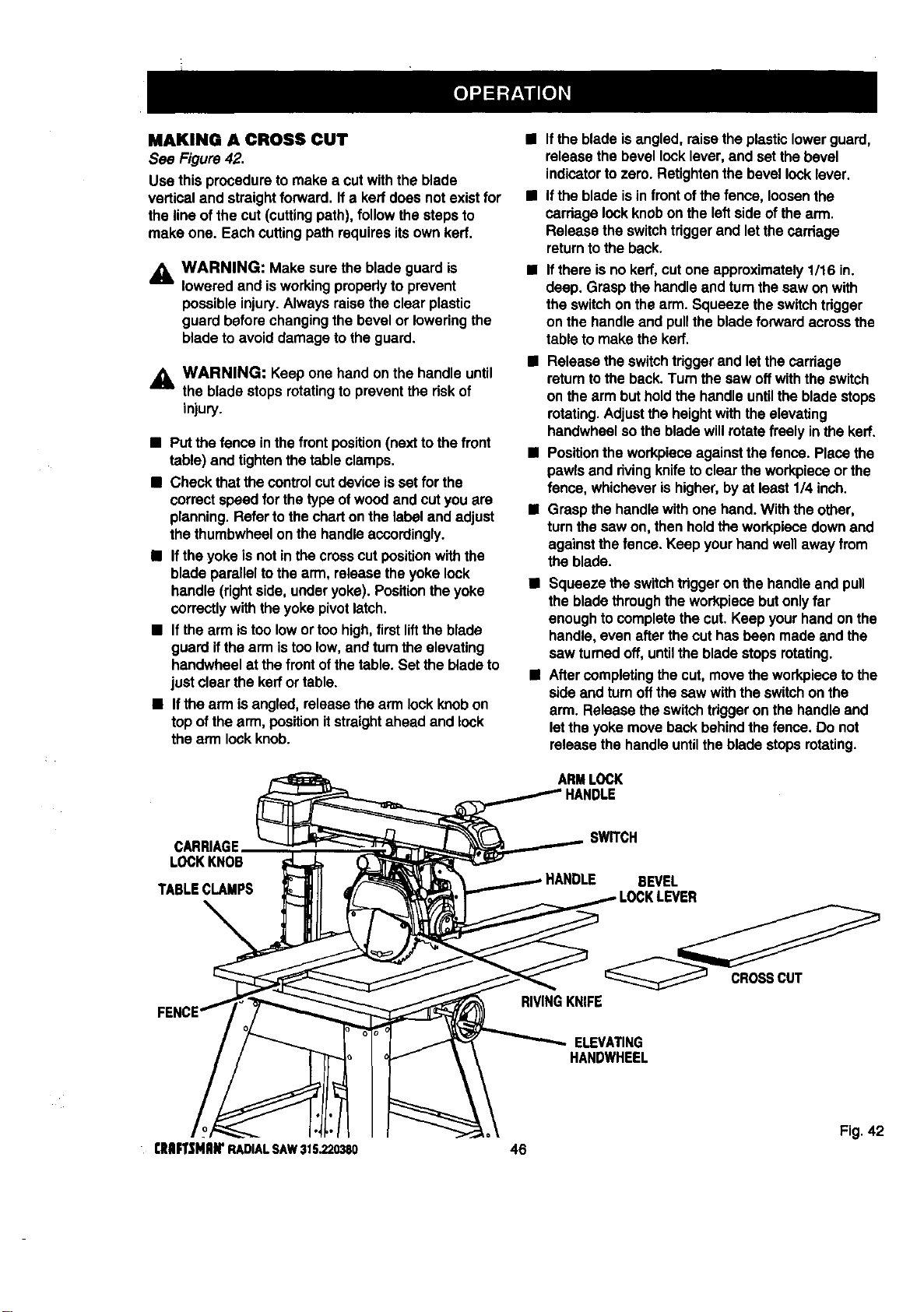
MAKING A CROSS CUT
See Figure42.
Use this proceduretomake a cutwiththe blade
verticaland straightforward. Ifa ken`does notexistfor
the line ofthe cut (cutting path),follow the stepsto
make one. Eachcuttingpath requiresitsown ken`.
_, WARNING: Make sure the bladeguard is
loweredand isworkingproperlyto prevent
possibleinjury.Alwaysraisethe clear plastic
guard beforechangingthe bevel or loweringthe
bladeto avoiddamage to theguard.
,_ WARNING: Keep one handon the handle until
H
the bladestops rotatingto preventthe riskof
injury.
• Putthe fence in thefront position(nexttothe front
table) and tightenthe tableclamps.
• Check thatthe controlcutdeviceisset for the
correctspeed forthe typeofwoodand cutyou are
planning.Referto thecharton the labeland adjust
thethumbwheelon the handleaccordingly.
• Iftheyoke isnot inthe crosscut positionwiththe
blade paralleltothe arm, release theyoke lock
handle (rightside,underyoke). Positiontheyoke
correctlywiththe yokepivotlatch.
• Ifthe arm istoo lowortoo high,first liftthe blade
guard ifthearm istoo low,and turntheelevating
handwheelat thefront ofthe table.Set the bladeto
just clear theken`or table.
• If the arm isangled, releasethe armlock knobon
top ofthearm, position itstraightahead and lock
the arm lockknob.
• Ifthe bladeisangled,raisethe plasticlowerguard,
release the bevel locklever,and set thebevel
indicatortozero. Retightenthebevel locklever.
• Ifthe bladeisin front ofthe fence, loosenthe
cardage lockknobon the leftside ofthe arm.
Release theswitchtriggerand letthecarriage
returnto theback.
• Ifthere is no ken',cutone approximately1/16 in.
deep.Grasp the handleand turnthesaw on with
theswitchonthe arm. Squeeze the switchtrigger
onthe handle and pullthe bladeforward acrossthe
tableto make the kerr.
• Release theswitchtdggerand letthecarriage
returntothe back.Turn the saw offwiththe switch
on thearm but holdthe handle untilthe bladestops
rotating.Adjustthe heightwiththe elevating
handwheelsothe bladewillrotatefreely in the ken'.
• Positiontheworkpieceagainstthe fence. Placethe
pawls and rivingknifeto clearthe workpieceor the
fence, whicheverishigher,by at least 114inch.
• Graspthe handlewithone hand. Withthe other,
turnthesaw on,then holdtheworkpiecedownand
againstthefence. Keep yourhandwellaway from
theblade.
• Squeeze the switchtriggeron thehandle and pull
the bladethroughthe workpiecebutonlyfar
enoughto completethe cut.Keep yourhandon the
handle,even afterthecut hasbeen made and the
saw turnedoff, untilthe bladestops rotating.
II Aftercompleting thecut, movethe workpiecotothe
side and turnoffthe saw withthe switchon the
arm. Release the switchtriggeron the handleand
lettheyoke movebackbehindthe fence. Do not
releasethe handle untiltheblade stopsrotating.
ARMLOCK
CARRIAGE
LOCKKNOB
SWITCH
BEVEL
CROSSCUT
RIVINGKNIFE
ELEVMING
HANDWHEEL
Fig. 42
13tlIFTSHAWRADIALSAW315.220380 46
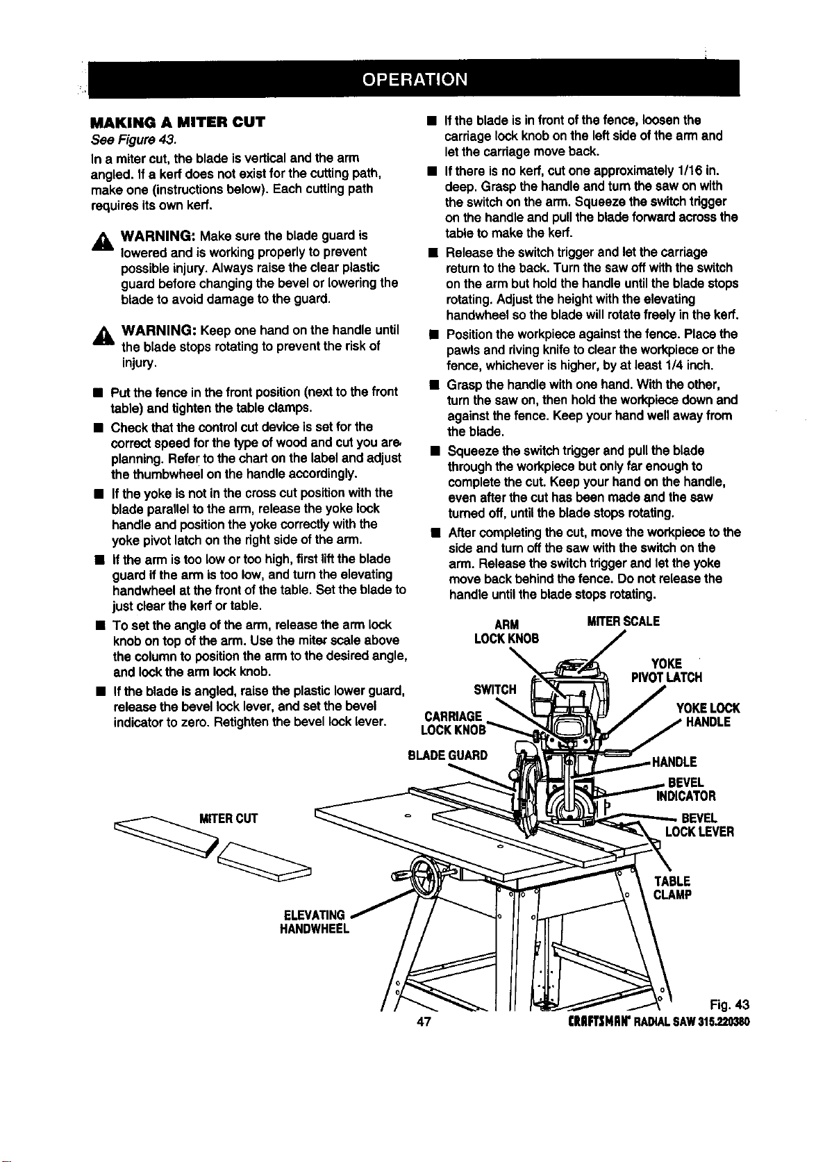
MAKING A MITER CUT
See Figure 43.
In a miter cut, the blade isverticaland the arm
angled. Ifa ked does not existforthe cuttingpath,
make one (instructionsbelow). Each cuttingpath
requiresitsown kerf.
WARNING: Make sure the bladeguard is
lowered and isworkingproperlyto prevent
possibleinjury.Always raisethe clear plastic
guard beforechangingthe bevel or loweringthe
blade toavoid damage tothe guard.
_1= WARNING: Keep one handon the handle until
the blade stops rotatingto preventthe riskof
injury.
• Put thefence in thefrontposition(nextto thefront
table) and tightenthe tableclamps.
• Check that thecontrolcutdevice issat for the
correct speed for the typeofwoodand cutyou ars
planning.Refer tothe charton the labeland adjust
the thumbwheelon thehandle accordingly.
• Ifthe yoke isnot inthe crosscutpositionwith the
blade parallelto thearm, releasethe yoke lock
handle and position theyokecorrectlywiththe
yoke pivotlatchon the right sideofthe arm.
• Ifthe arm istoo lowor too high,first lifttheblade
guardifthe arm istoo low,andturnthe elevating
handwheelat thefront ofthetable. Set the bladeto
just clearthe kerrortable.
• To set the angle ofthe arm, release thearm lock
knobon top ofthe arm. Use themite_scale above
the column to position the arm tothe desiredangle,
and lockthe arm lockknob.
• Ifthe blade isinfrontof thefence, loosenthe
carriagelockknobonthe leftside ofthearm and
letthe carriagemoveback.
• Ifthere isno kerf,cutone approximately 1/16 in.
deep. Grasp the handleand turnthe saw on with
the switchon the arm. Squeeze theswitchtrigger
on the handleand pullthe bladeforward across the
table to make thekerf.
• Release the switchtriggerand letthe carriage
returntothe back.Turn thesaw offwiththe switch
on thearm but holdthe handle untiltheblade stops
rotating.Adjustthe heightwiththeelevating
handwheelsothe bladewillrotatefreely inthe kerr.
• Positiontheworkpieceagainstthefence. Placethe
pawls and rivingknifeto clear theworkplaceor the
fence, whicheverishigher,byat least1/4 inch.
• Graspthe handlewith one hand.Withthe other,
turnthe saw on,then holdthe workpiecedownand
againstthe fence. Keep yourhandwellaway from
the blade.
• Squeeze the switchtriggerand pulltheblade
through the workpiecebut onlyfar enoughto
completethe cut. Keep yourhandon thehandle,
even afterthe cuthas been madeand the saw
turned off,untilthebladestopsrotating.
• After completingthe cut,movethe workpiecetothe
side and turnoffthesaw with theswitchon the
arm. Releasethe switchtriggerand let theyoke
move backbehindthefence. Do notrelease the
handleuntilthe bladestopsrotating.
ARM MITERSCALE
LOCKKNOB
• Ifthe blade isangled,raisethe plasticlowerguard, SWITCH
releasethe bevellock lever,and set the bevel
indicatorto zero. Retightenthe bevellocklever. CARRIAGE
YOKE
PIVOTLATCH
YOKELOCK
BLADEGUARD
MITERCUT
INDICATOR
LOCKLEVER
ELEVATING
HANDWHEEL
TABLE
CLAMP
Fig. 43
47 CRAFTSMAN"RADIALSAW315.220380
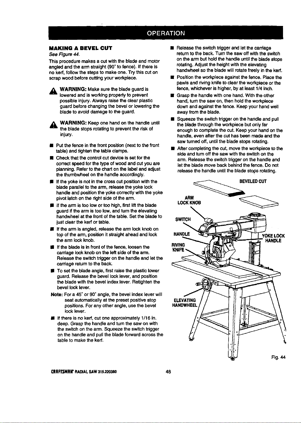
MAKING A BEVELCUT
See Figure44.
This proceduremakes a cutwiththe blade and motor
angled and the arm straight(90"tofence). If there is
no kerf, followthe stepsto make one. Try this cuton
scrapwood beforecuttingyourworkpiece.
_i, WARNING: Make sure theblade guard is
lowered and isworkingproperlyto prevent
possibleinjury.Always raisethe clear plastic
guard beforechangingthe bevel or loweringthe
blade toavoid damage tothe guard.
,_ WARNING: Keep one handon the handle until
the bladestopsrotatingto preventthe risk of
injury.
• Putthe fence in thefrontposition(nextto thefront
table) and tightenthetable clamps.
• Check thatthecontrolcutdeviceisset for the
correctspeed for the typeofwoodand cutyou are
planning.Referto thechart onthe labeland adjust
the thumbwheelon the handleaccordingly.
• Iftheyoke isnotin the crosscutpositionwiththe
bladeparalleltothe arm, release the yokelock
handleand positionthe yokecorrectly withtheyoke
pivotlatchonthe rightside ofthearm.
• Ifthe arm istoo lowor toohigh,firstliftthe blade
guardifthe armistoo low,and tum theelevating
handwheelat thefront ofthe table.Set theblade to
justclearthe kerrortable.
• Ifthe arm isangled,release thearm lock knobon
topof thearm, positionitstraightahead and lock
thearm lockknob.
• Iftheblade isin frontofthe fence, loosenthe
carriage lockknobon the leftsideofthe arm.
Release theswitchtdggeronthe handleand letthe
carriage returnto the back.
• To set the bladeangle,first raise the plasticlower
guard.Release the bevel locklever,and position
theblade withthe bevelindexlever.Refightenthe
bevel locklever.
Note: Fora 45"or 90" angle, thebevel indexlever will
seat automaticallyat the presetpositivestop
positions.Forany otherangle, usethe bevel
lock lever.
• Ifthere isno kerr,cutone approximately1/16 in.
deep. Graspthe handleand turnthe saw on with
the switchonthe arm. Squeeze the switchtrigger
onthe handleand pullthe bladeforward acrossthe
tableto make the kert.
• Release the switchtriggerand letthe carriage
returnto the back,Turn the saw offwiththeswitch
on thearm but holdthe handleuntilthe bladestops
rotating.Adjustthe heightwiththe elevating
handwheelsothe bladewillrotatefreely in thekerr.
• Positionthe workpieceagainstthefence. Placethe
pawls and rivingknifetoclear theworkpieceorthe
fence, whicheverishigher,by at least 114inch,
• Grasp the handlewith one hand, Withthe other
hand,turnthe saw on,then holdthe workpiece
downand againstthe fence. Keep yourhandwell
away from the blade.
• Squeeze the switchtriggeron the handleand pull
the bladethroughtheworkplacebutonlyfar
enoughtocompletethe cut. Keep yourhand onthe
handle,even afterthe cuthas been madeand the
saw turnedoff, untilthe bladestops rotating.
• Aftercompletingthe cut,move theworkpiecetothe
side and turnoffthesaw withthe switchon the
arm. Release the switchtriggeronthe handleand
letthe blademove backbehind thefence. Do not
release thehandle untilthe blade stopsrotating.
VELEDCUT
SWITCH
HANDLE
RIVING
YOKELOCK
HANDLE
ELEVATING
HANDWHEEL
Fig. 44
(IIRFrSNRIr RADIALSAW315.220380 48
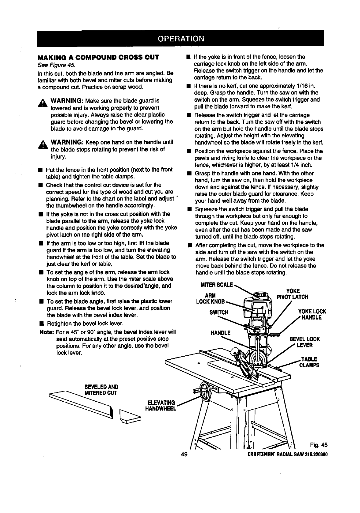
MAKING A COMPOUND CROSS CUI"
See Figure45.
In thiscut, boththe bladeand the arm are angled. Be
familiarwith bothbevel and mitercutsbefore making
a compoundcut. Practiceon scrapwood.
_1= WARNING: Make sure the bladeguard is
lowered and isworkingproperlyto prevent
possibleinjury.Always raise theclear plastic
guard before changingthe bevel or loweringthe
bladeto avoiddamage to the guard.
_k WARNING: Keep one handon the handleuntil
the bladestops rotatingto preventthe riskof
injury.
• Putthefence in thefrontposition(nextto the front
table) and tightenthe tableclamps.
• Check thatthe controlcutdevice isset for the
correct speed for the typeof woodand cut youare
planning.Refer tothe charton the labeland adjust '
the thumbwheelonthe handle accordingly.
• If the yokeIs notinthe crosscutpositionwiththe
blade parallelto thearm, releasethe yoke lock
handle and positiontheyokecorrectlywiththe yoke
pivotlatchon the dghtside ofthe arm.
• Ifthe arm istoo lowortoo high,first liftthe blade
guard ifthe arm istoo low,and turnthe elevating
handwhealat thefront ofthetable, Set the bladeto
just clearthe kerfortable.
• To set the angleofthe arm, release the arm look
knobon topof thearm. Usathe miterscale above
the columnto positionitto the desired'angle,and
look the arm look knob.
• To set theblade angle,firstraise the plasticlower
guard. Release the bevel locklever,and position
the blade withthebevel indexlever.
• Retightenthe bevel looklever.
Note: Fora 45"or 90" angle, thebevel index lever will
seat automatically at the presetpositivestop
positions. Forany otherangle, usathe bevel
locklever.
• If theyoke isinfrontofthefence, loosen the
carriage lookknobon the left side ofthe arm.
Release the switchtriggeronthe handleand letthe
cardage retumto theback.
• Ifthere isno kerr,cutone approximately1/16 in.
deep. Graspthe handle.Turnthe saw onwiththe
switchon the arm. Squeeze theswitchtriggerand
pulltheblade forwardto makethe kerr.
• Release the switchtriggerand letthe carriage
returntothe back.Turn the saw Offwiththe switch
on thearm but holdthe handle untiltheblade stops
rotating.Adjustthe heightwiththe elevating
handwheelsothe bladewillrotatefreely inthe kerf.
• Positiontheworkpieceagainstthefence. Placethe
pawlsand rivingknife toclear theworkpieceor the
fence, whicheverishigher,byat least114inch.
• Graspthe handle withone hand.Withthe other
hand,turnthe saw on,then holdtheworkpiece
downand againstthefence. Ifnecessary,slightly
raisethe outerbladeguardfor clearance.Keep
yourhandwell away from theblade.
• Squeeze the switchtriggerand pulltheblade
throughthe workpiecebut onlyfar enoughto
completethe cut. Keep yourhandonthe handle,
even after the cuthas been madeand the saw
turned off,untilthebladestopsrotating.
• After completingthe cut,movethe workpiecetothe
sideand turnoffthesew withthe switchon the
arm. Release the switchtdggerand letthe yoke
moveback behind thefence. Do notreleasethe
handle untilthe bladestopsrotating.
ARM
SWITCH
YOKE
PIVOTLATCH
YOKELOCK
HANDLE
BEVELLOCK
BEVELEDAND
ELEVA_NG
HANDWHEEL
Fig. 45
49 (RRFT|NRIrRADIALSAW315.220380
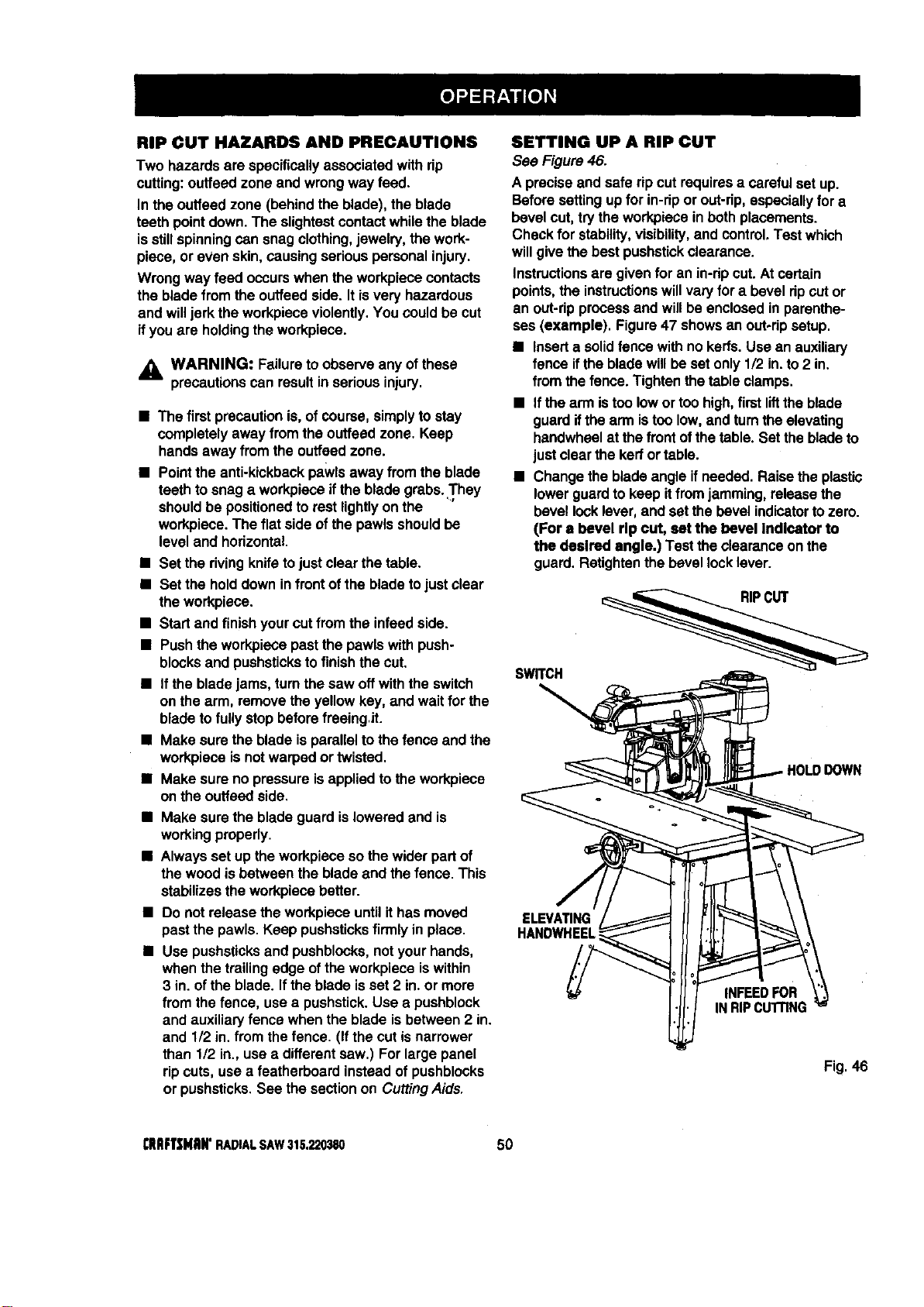
RIP CUT HAZARDS AND PRECAUTIONS
Two hazards are specificallyassociatedwithrip
cutting:ouffeedzone and wrongway feed.
In the outfeedzone (behindthe blade), the blade
teethpointdown. The slightestcontactwhilethe blade
isstillspinningcan snag clothing,jewelry, the work-
piece, or even skin,causing seriouspersonalinjury.
Wrongway feed occurswhen the workpiececontacts
the bladefrom the outfeedside. Itisvery hazardous
and willjerk the workpieceviolently.You could be cut
ifyou are holdingtheworkpiece.
_, WARNING: Failureto observeany ofthese
precautionscan resultinserious injury.
• The firstprecautionis, ofcourse, simplytostay
completelyaway from theouffeed zone. Keep
handsaway from the outfeedzone.
• Pointtheanti-kickbackpawlsaway from the blade
teeth tosnag a workpieceifthe blade grabs..They
shouldbe positionedtorest lightlyon the
workpiece.The flat side of the pawlsshouldbe
level and horizontal.
• Set the rivingknifetojust clear the table.
• Set the holddown infrontofthe bladetojust clear
the workpiece.
• Start and finish yourcutfrom the infeedside.
• Push theworkpiecepastthe pawls with push-
blocksand pushsticksto finishthe cut.
• If the bladejams, turnthe saw offwiththe switch
on the arm, remove the yellowkey, and waitfor the
bladeto fully stop beforefreeingJt.
• Make sure the blade isparallelto thefence and the
workpieceis notwarpedor twisted.
• Make sure no pressureisappliedto theworkpiece
on the outfeedside.
• Make sure the bladeguard islowered and is
workingproperly.
• Always set up the workpiecesothe widerpart of
thewood isbetween the bladeand thefence. This
stabilizestheworkpiecabetter.
• Do not release theworkpieceuntil ithasmoved
pastthe pawls.Keep pushsticksfirmly inplace.
• Use pushsticksand pushblocks,notyourhands,
when the trailingedge ofthe workpieceiswithin
3 in.ofthe blade. Ifthe blade isset 2 in.or more
from thefence, usea pushstick.Use a pushblock
and auxiliaryfence when the blade is between2 in.
and 1/2 in. from the fence. (Ifthe cutis narrower
than 1/2 in., usea differentsaw.) For largepanel
ripcuts, usea featherboard insteadof pushblocks
or pushsticks.See the sectionon CuttingAids.
SETTING UP A RIP CUT
See Figure 46.
A preciseand safe ripcutrequiresa careful set up.
Beforesettingupfor in-ripor out-rip,especiallyfor a
bevel cut,try the workpieceinbothplacements.
Check for stability,visibility,and control.Testwhich
willgive thebest pushstickclearance.
Instructionsare givenfor an in-ripcut.At certain
points,the instructionswillvaryfor a bevel ripcutor
an out-ripprocessand willbe enclosedin parenthe-
ses (example). Figure47 showsan out-ripsetup.
• Inserta solidfence withno kerfs.Use an auxiliary
fence ifthe bladewillbeset only1/2 in.to 2 in.
from thefence. Tightenthetable clamps.
• Ifthe arm istoo lowor toohigh,firstliftthe blade
guardifthe arm istoo low,and turnthe elevating
handwheelat the front ofthe table. Set the bladeto
just clear thekerfor table.
• Change the bladeangle ifneeded. Raisethe plastic
lowerguardto keep itfrom jamming,releasethe
bevel locklever,and setthe bevel indicatortozero.
(For a bevel rip cut, set the bevel Indicator to
the desired angle.) Test theclearanceonthe
guard. ReUghtenthe bevel locklever.
SWRCH
IOWN
HANDWHEEL
INFEEOFOR
INRIPCUTrlNG
Fig.46
I;RllFTSHItN'RADIALSAW315.220380 50
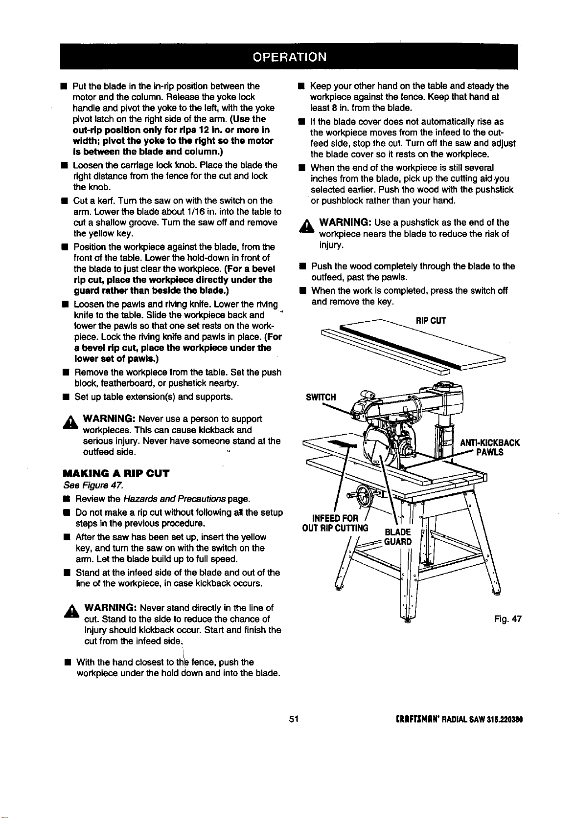
• Putthe blade inthe in-rippositionbetweenthe
motorand the column.Release theyoke look
handle and pivottheyoketo the left,withthe yoke
pivot latch onthe rightsideof the arm. (Use the
out-rip position only for rlpa 12 in. or more in
width; pivot the yoke to the right so the motor
is between the blade and column.)
• Loosenthe cardagelookknob. Place thebladethe
dghtdistancefrom thefencefor thecut and lock
the knob.
• Cut a kerf.Turn the saw onwiththe switchonthe
arm. Lowerthe bladeabout1/16 in.intothe tableto
cut a shallowgroove.Turnthe sew offand remove
theyellowkey.
• Positionthe workpieceagainstthe blade,from the
frontofthe table. Lowerthe hold-downinfrontof
the bladetojustclearthe workpiece.(For a bevel
rip cut, place the workplece directly under the
guard rather than beside the blade.)
• Loosenthe pawlsand rivingknife.Lowerthe dving,
knifeto thetable. Slidetheworkpiecebackand
lowerthe pawlsso thatone set restsonthe work-
piece. Lockthe rivingknifeand pawlsin place.(For
a bevel rip cut, place the workplece under the
lower set of pawls.)
• Remove theworkpiecefromthe table. Set thepush
block,featherboard,or pushsticknearby.
• Set uptable extension(s)and supports.
_i, WARNING: Never usea persontosupport
workpieces.Thiscan cause kickbackand
sedous injury.Never have someonestand at the
outfeed side.
MAKING A RIP CUT
See Figure47.
• Reviewthe Hazards and Precautionspage.
• Do not make a dp cutwithoutfollowingallthe setup
stepsinthe previousprocedure.
• Afterthe saw hasbeen set up,insertthe yellow
key, and turnthe saw on withthe switchon the
arm. Lettheblade buildup tofullspeed.
• Stand at the infsedsideof the bladeand out ofthe
lineof theworkpiece,incase kickbackoccurs.
_i WARNING: Never stand directlyin the lineof
cut. Stand tothe side to reducethe chance of
injuryshouldkickbackoccur. Startand finishthe
cutfrom the infeedside=
/
• Withthe handclosestto th_fence, pushthe
workpieceunderthe holddownand intothe blade.
• Keep yourotherhandon the table andsteadythe
workpieceagainstthefence. Keep thathandat
least8 in.fromthe blade.
• if theblade cover does notautomaticallydsa as
the workpiecemovesfrom the infeedtothe out-
feed side, stopthe cut.Turn offthe saw and adjust
the bladecover so itrestson theworkpiece.
• When the end ofthe workpieceis stillseveral
inchesfrom the blade, pick upthe cuttingaid .you
selected earlier. Pushthe woodwiththe pushstick
,orpushblockratherthan yourhand.
_k WARNING: Use a pushstickas the end ofthe
workpiecenears the bladeto reducethe riskof
injury.
• Push thewoodcompletelythroughthe bladetothe
ouffeed,pastthe pawls.
• When thework iscompleted,presstheswitchoff
and removethe key.
SWITCH
ANTkKICKBACK
PAWLS
INFEEDFOR
OUTRIPCUTrlNG BLADE
Fig. 47
51 CRRFI"$NRN'RADIALSAW315.220380
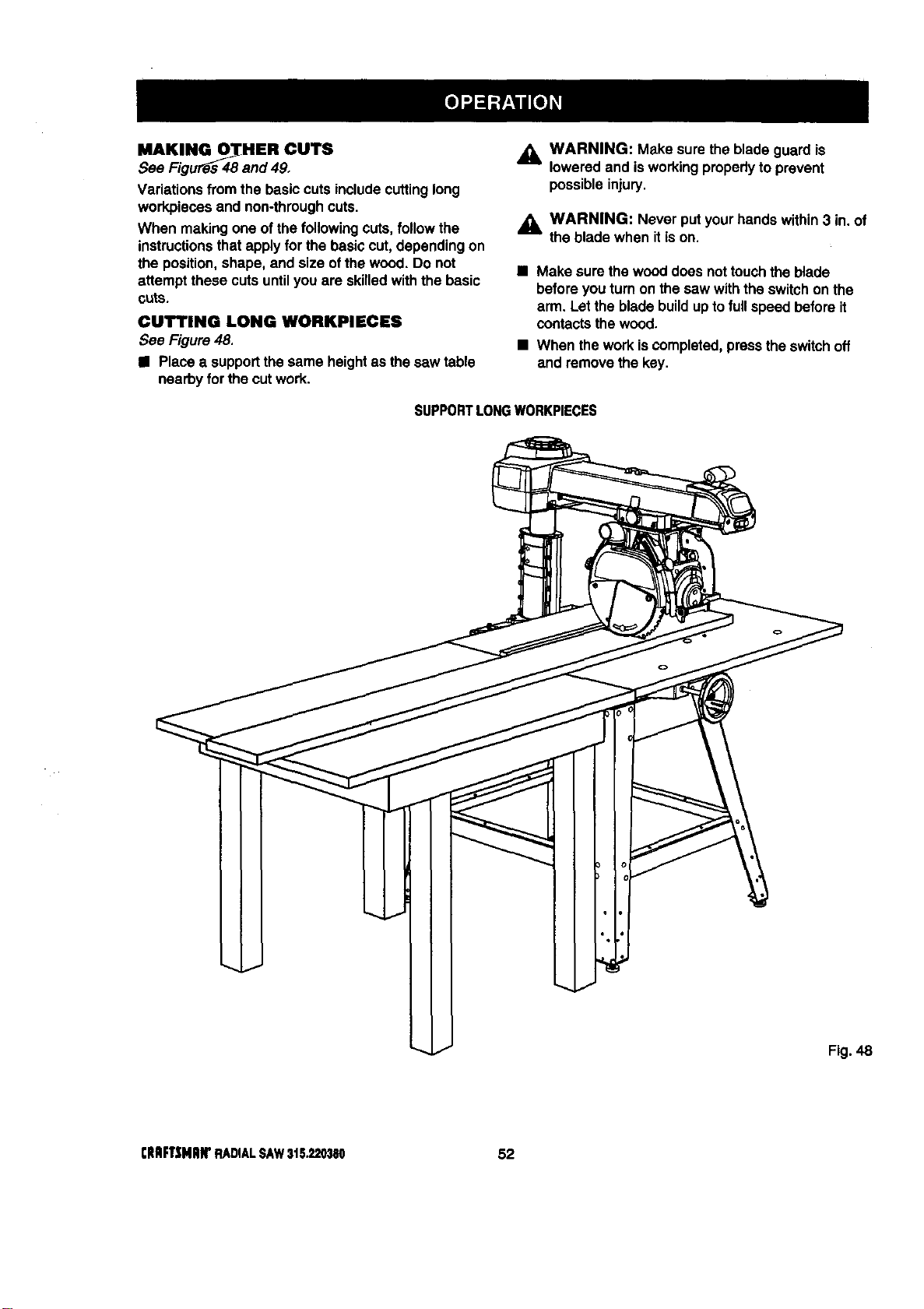
MAKINGO_HER OUTS
See Figu_s 48 and 49,
Variationsfrom the basic cutsincludecuttinglong
workpiecesand non-throughcuts.
When makingone ofthe following cuts, followthe
instructionsthatapplyfor the basiccut, dependingon
the position,shape, and size ofthe wood. Do not
attempt these cutsuntilyou are skilledwiththe basic
cuts.
CUTTING LONG WORKPIECES
See Figure48.
• Place a supportthe same heightas the saw table
nearbyfor the cutwork.
,_ WARNING: Make sure the blade guardis
loweredand isworkingproperlyto prevent
possibleinjury.
,_ WARNING: Never putyourhandswithin3 in.of
the bladewhen itison.
• Make surethe wooddoes nottouchthe blade
before youturnon the saw withthe switchonthe
arm. Letthe blade buildupto full speed beforeit
contactsthewood.
• When the work iscompleted,pressthe switchoff
and remove thekey.
SUPPORTLONGWORKPIECES
Fig. 48
rltmFT_iNRIrRADIALSAW31S._'0380 52
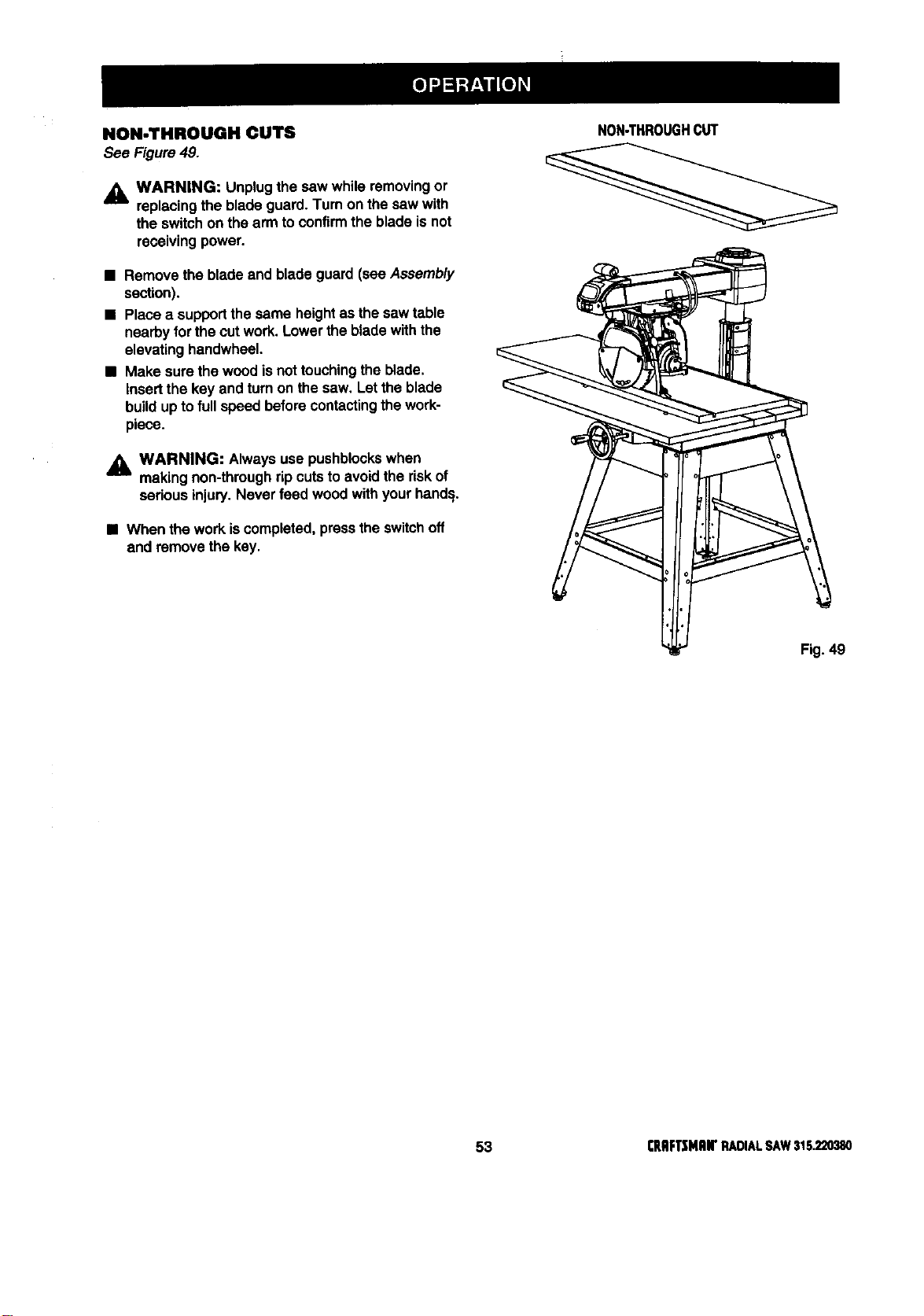
NON-THROUGH CUTS
See Figure49.
,_L WARNING: Unplugthe saw while removingor
replacingthe blade guard.Turn on the saw with
the switchon the armto confirmthe blade isnot
receivingpower.
NON-THROUGHCUT
• section).Rem°vethe bladeand blade guard (see Assembly ___
• Place a supportthe same heightas thesaw table
nearbyforthe cutwork.Lowerthe bladewiththe
elevatinghandwheel.
• Make sure the woodisnot touchingtheblade.
Insertthe key and turnon the saw. Let theblade
buildupto fullspeed beforecontactingthe work-
piece.
WARNING: Always use pushblockswhen
--'-- makingnon-throughripcutsto avoidthe riskof
seriousinjury.Never feed wood withyourhand=i,
k
• When the workiscompleted,pressthe switchoff \
and removethe key,
Fig. 49
53 rRIIFTSMRWRADIALSAW316.220380
CiENERAL MAINTENANCE
_i, WARNING: When servicing,useonlyidentical
Craftsman replacementparts.Use of any other
part may create e hazard or causeproduct
damage.
_k WARNING: To preventaccidentalstartingthat
could cause possible sedouspersonalinjury,turn
offthe saw withthe switchon the arm, remove
the switch key,and unplugthe saw before
workingon the radial saw.
• Remove sawdustfrom the workarea, including
inside the blade cover,frequently.
• Remove sawdustfrom and clean the blade guards
frequently.
• Clean plasticpartswith a softdamp cloth. Do not
useany strongsolvents.
_b, WARNING: Do notat anytime let brake fluids,
gasoline, petroleum-basedproducts,penetrating
oils, etc. contactplasticparts.They contain
chemicalsthat can damage,weaken or destroy
plastic.
• Check teeth of anti-kickbackpawls;sharpen with
file if needed.
• Regularlycheckall nuts,bolts, screws,and cables
for tightnessand condition.
MOTOI_IELEGTIIIlCAL
• Frequentlyvacuumor blowoutany sawdustfrom
the workareas.
_k WARNING: If the powercordsarewom, cut, or
damaged inany way, have them replaced
immediatelybya qualifiedservice technicianat a
Sears store or repaircenter. Failureto do so
could resultin sedouspersonalinjury.
_IL WARNING; To avoidfire or electrocution,
reassembleelectricpartsonlywith identical
Craftsmanreplacement pads. Reassemble
exactlyas originallyassembled.
CRIIFTSNnN'RADIALSAW315220380 54
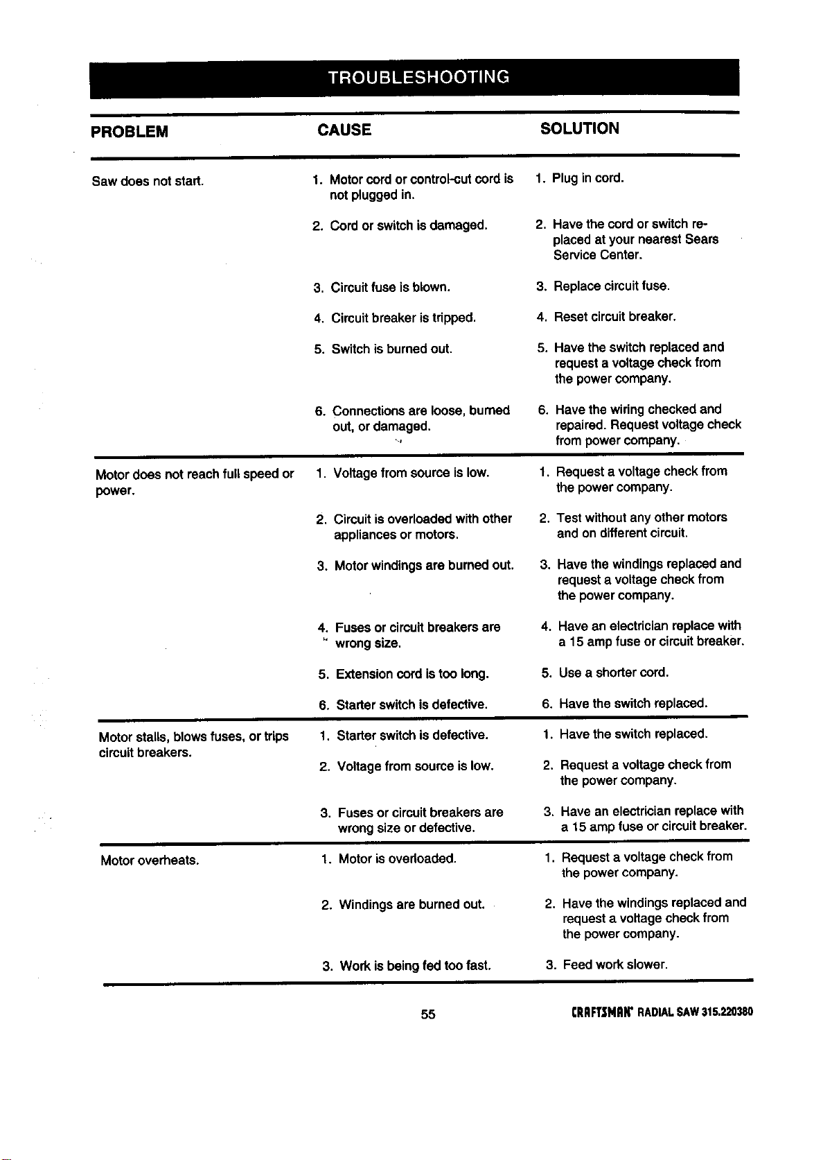
PROBLEM CAUSE SOLUTION
Saw does not start. I. Motorcordor control-cutcord is I. Plugincord.
not pluggedin.
2. Cord or switchisdamaged.
2. Have the cordorswitch re-
placedat your nearest Sears
Service Center.
3. Circuitfuseis blown. 3. Replacecircuitfuse.
4, Circuit breaker istripped.
4. Resetcircuitbreaker.
5. Switch isburnedout. 5. Have the switchreplacedand
requesta voltagecheckfrom
the powercompany.
6. Connectionsare loose, burned
out,or damaged.
Lf
6, Have thewiringcheckedand
repaired. Requestvoltagecheck
frompowercompany.
Motordoes not reachfull speed or
power.
1. Voltage fromsourceis low.
2. Circuitis overloadedwithother
appliancesor motors.
1_ Requesta voltagecheckfrom
the powercompany.
2. Test withoutanyothermotors
and on differentcircuit.
3. Motor windingsare burnedout.
3. Have the windingsreplaced and
requesta voltagecheckfrom
the powercompany.
4, Fuses or circuitbreakersare
wrongsize,
4. Have an electricianreplacewith
a 15 ampfuse or circuitbreaker.
5. Extensioncord istoo long.
5. Use a shortercord.
6. Starterswitchis defective. 6. Have theswitchreplaced.
Motor stalls,blowsfuses, ortrips
circuitbreakers.
1. Starter switchisdefective.
2, Voltagefrom sourceis low.
1. Have the switchreplaced.
2. Requesta voltagecheckfrom
the powercompany.
3. Fuses or circuitbreakersare
wrongsize or defective.
3. Have an electricianreplacewith
a 15 amp fuse or circuitbreaker.
Motoroverheats.
1. Motor isovedoaded. 1. Requesta voltagecheckfrom
the powercompany.
2. Windings are burnedout.
2. Have thewindingsreplacedand
requesta voltagecheckfrom
the powercompany.
3. Work isbeing fed toofast.
3. Feed workslower.
55 CRAFTSNAW RADIAL SAW 315.220380
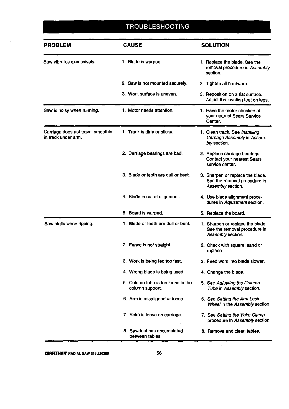
PROBLEM CAUSE SOLUTION
Saw vibmtas excessively. I. Bladeis warped.
1, Replacethe blade. See the
removalprocedurein Assembly
section,
2. Saw isnot mountedsecurely, 2, Tightenall hardware.
3. Worksurface is uneven.
3. Reposition on a flat surface.
Adjust the leveling feet on legs.
Saw isnoisywhen running.
1. Motor needs attention.
1. Have the motorcheckedat
yournearest Sears Service
Center.
Carriage does nottravel smoothly
in track underarm.
1. Track is dirtyor sticky.
1. Clean track. See Installing
CarriageAssemblyin Assem-
bly section.
2. Carriagebeadngs are bad.
2. Replacecerdage bearings.
Contactyour nearestSears
servicecenter.
3. Bladeor teeth are dull or bent.
3. Sharpen or replacethe blade.
See the removalprocedurein
Assemblysection.
4. Blade isout ofalignment. 4. Use bladealignmentproce-
duresin Adjustmentsection.
5. Boardiswarped. 5. Replace the board,
Saw stallswhen dpping.
1. Bladeor teeth are dull orbent.
1. Sharpen or replacethe blade.
See the removalprocedurein
Assemblysection.
2. Fence isnot straight. 2. Check withsquare;sand or
replace.
3. Work isbeing fedtoo fast. 3. Feed workintobladeslower.
4. Wrong bladeis being used. 4. Change the blade.
5. Columntube is too looseinthe
columnsupport.
5. See Adjustingthe Column
Tubein Assemblysection.
6. Arm ismisalignedor loose. 6. See Settingthe Arm Look
Wheelinthe Assemblysection.
7. Yoke is loose on carriage. 7, See Settingthe YokeClamp
procedurein Assemblysection,
8. Sawdust has accumulated
between tables.
8. Remove and clean tables.
I:HFt'$NIUr RADIALSAW315.220380 56
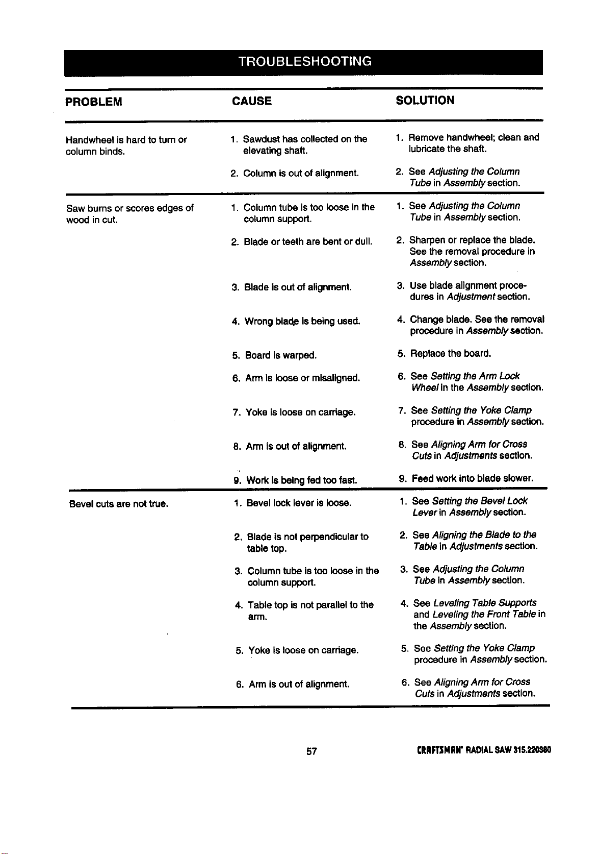
PROBLEM CAUSE SOLUTION
Handwheel is hardtoturnor I. Sawdust hascollectedon the I. Remove handwheel;clean end
columnbinds, elevating shaft, lubricatethe shaft.
2, Columnis outof alignment. 2. See Adjustingthe Column
Tubein Assemblysection.
Saw burnsor scores edges of 1. Columntube istoo looseinthe 1. See Adjustingthe Column
woodin cut. columnsupport, Tubein Assemblysection,
2. Blade orteeth are bentor dull.
2. Sharpen or replacethe blade.
See the removalprocedurein
Assemblysection.
3. Bladeisout of alignment.
3. Use bladealignmentproce-
duresin Adjustmentsection.
4. Wrongblade isbeing used.
4. Change blade. See the removal
procedurein Assemblysection.
5, Board iswarped.
5. Replacethe board.
6. Arm is loose or miseligned.
6. See SettingtheArm Lock
Wheelin theAssemblysection.
7. Yoke islooseon carriage.
7. See Settingthe Yoke Clamp
procedurein Assemblysection.
Bevel cutsare nottrue.
8. Arm isout of alignment, 8.
9. Work Is being fed toofast. 9.
1. Bevel lock lever isloose, 1.
See AligningArm for Cross
Cuts in Adjustmentssection.
Feed workintoblade slower.
See SettingtheBevel Lock
Leverin Assemblysection.
2. Blade is notperpendicularto
table top.
3. Columntube istoo loose inthe
columnsupport.
4. Table top isnot paraUeltothe
arm.
2. See Aligningthe Blade tothe
Tablein Adjustmentssection.
3. See Adjustingthe Column
Tubein Assemblysection.
4. See LevelingTable Supports
and Levelingthe Front Tablein
the Assemblysection,
5, Yoke islooseon carriage,
5, See Settingthe YokeClamp
procedurein Assemblysection.
6. Arm isout ofalignment.
6. See AligningArm for Cross
Cuts inAdjustmentssection.
57 CRAFTSHIIN'RADIALSAW315.220380
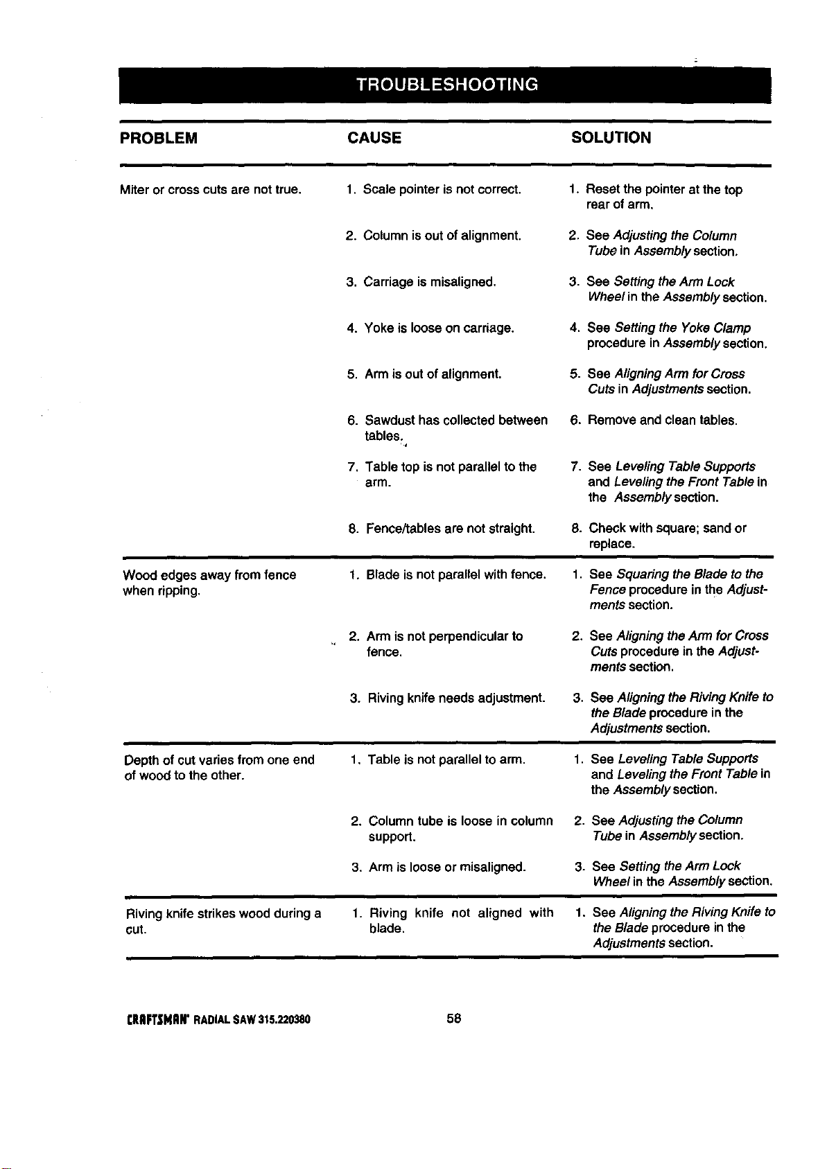
PROBLEM CAUSE SOLUTION
Miter or crosscutsare nottrue, 1. Scale pointeris notcorrect. 1. Resetthe pointerat the top
rear ofarm.
2. Columnisout ofalignment. 2. See Adjustingthe Column
Tubein Assemblysection.
3. Carriage ismisaligned. 3. See Setting the Arm Lock
Wheel in the Assembly section.
4. Yoke is looseon carriage. 4. See Settingthe YokeClamp
procedurein Assemblysection.
5. Armis outof alignment. 5. See AligningArm for Cross
Cuts inAdjustmentssection.
6. Sawdust hascollected between
tables.
,t
7. Table top is notparallel to the
arm.
6. Remove and clean tables.
7. See Leveling TableSupports
and Leveling the Front Tablein
the Assemblysection.
8. Fence/tablesare not straight. 8. Check with square;sandor
replace.
Wood edges away from fence
when ripping.
1. Blade isnot para!lel withfence. 1. See Squaring theBlade tothe
Fence procedurein the Adjust-
mentssection.
2. Arm is notperpendicularto
fence.
2. See AligningtheArm for Cross
Cutsprocedurein the Adjust-
mentssection.
3. Rivingknife needs adjustment.
3. See Aligning theRivingKnife to
the Bladeprocedureinthe
Adjustmentssection,
Depthof cutvaries from one end
ofwoodto the other.
1. Table is not parallel to arm.
1. See Leveling Table Supports
and Leveling the Front Table in
the Assembly section.
2. Columntube is loosein column 2. See AdjustingtheColumn
support. TubeinAssemblysection.
3. Arm is loose or misaligned.
3. See Setting the Arm Lock
Wheel in the Assembly section.
Riving knife strikeswoodduring a
cut.
1. Riving knife not aligned with 1. See Aligningthe Riving Knife to
blade, the Blade procedure in the
Adjustments section.
rlIRFTSNRIr RADIALSAW315.220380 58
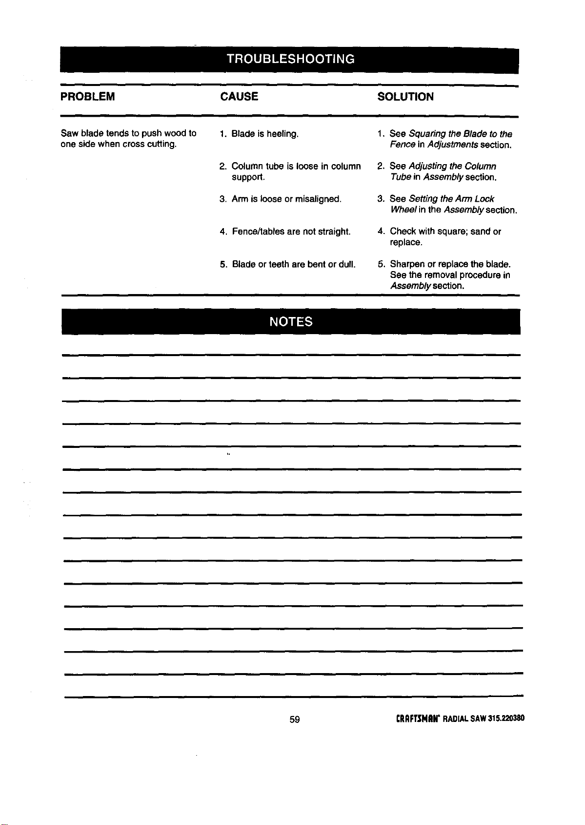
PROBLEM CAUSE SOLUTION
i
Saw bladetends to pushwoodto 1. Blade isheeling. 1, See SquaringtheBlade to the
one side when crosscutting, Fence inAdjustmentssection,
2. Columntube isloose in column 2, See Adjustingthe Column
support. Tubein Assemblysection.
3, Arm islooseor misaligned, 3. See SettingtheArm Lock
Wheelinthe Assemblysection,
4, Fence/tablesare not straight, 4. Check with square;sand or
replace.
5. Bladeor teeth are bent or dull. 5, Sharpen or replacethe blade.
See the removalprocedurein
Assemblysection.
59
illm
CRnFTSNnN"RADMLSAW315.220380
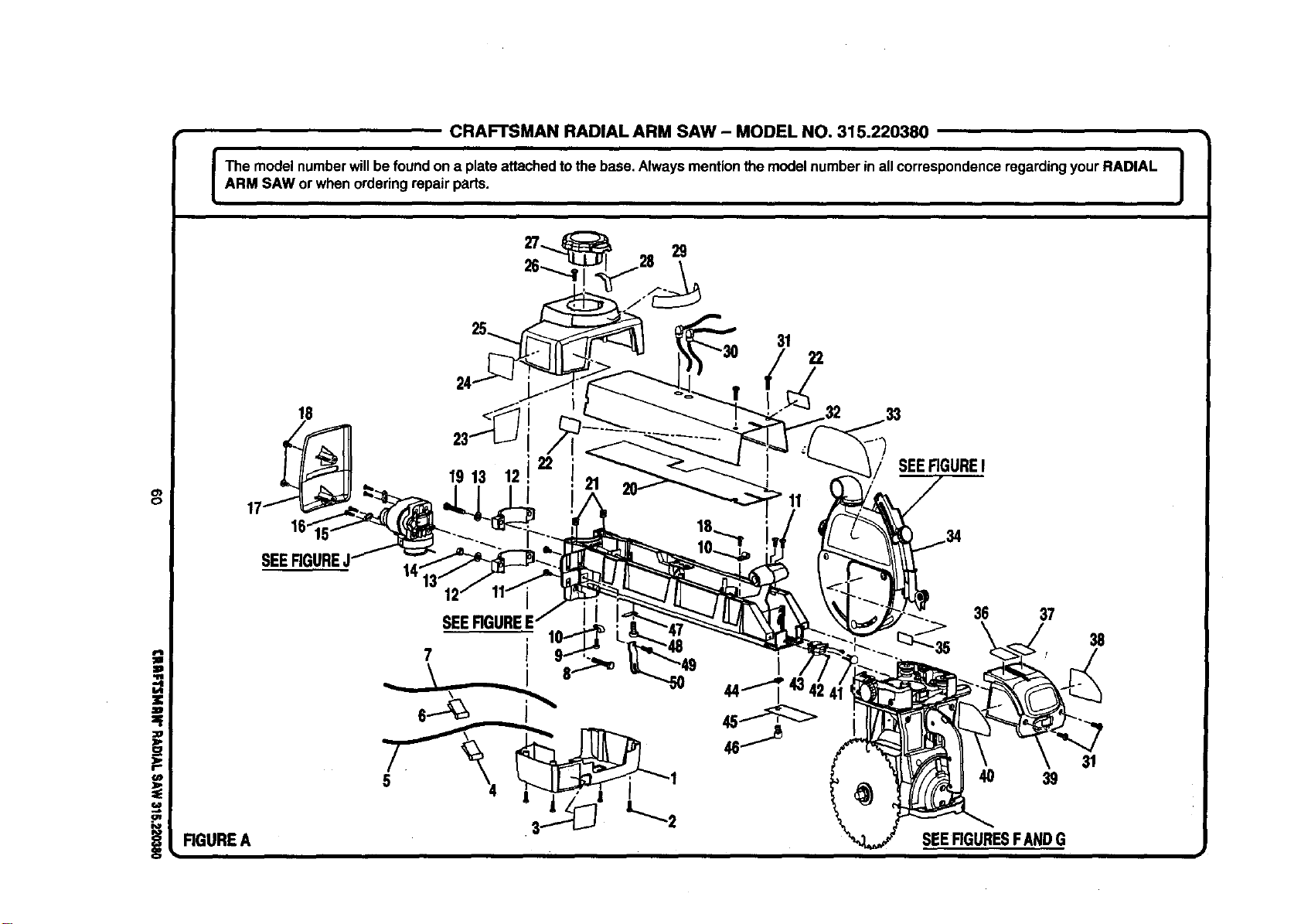
CRAFTSMAN RADIAL ARM SAW - MODEL NO, 315.220380
I The modelnumberwillbe foundon a plate attachedto thebase. Always mentionthe modelnumberin allcorrespondenceregardingyour RADIAL |
=
ARM SAW or whenorderingrepair parts.
J
29
31
22
0
!
18
19 13
22
12
SEERGUREI
SEER
36 37
38
4O 39
SEEFIGURESFANDG
31
RGUREA
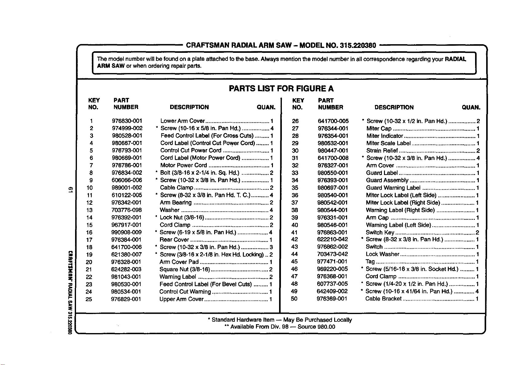
=_.
11r
r-
o_
€4R
i
CRAFTSMAN RADIAL ARM SAW - MODEL NO. 315.220380
I be modelnumberwillbefoundon a plateattachedto thebase. Always mentionthe modelnumberinall correspondenceregardingyourRADIAL I
ARM SAW or whenorderingrepairparts.
J
f
KEY PART
NO. NUMBER
1 976830-001
2 974999-002
3 980528-001
4 980667-001
5 976793-001
6 980669-001
7 976786-001
8 976834-002
9 606066-006
10 989001-002
11 610122-005
12 976342-001
13 703776-098
14 976392-001
15 967917-001
16 990908-009
17 976384-001
18 641700-006
19 621380-007
20 976328-001
21 624282-003
22 981043-001
23 980530-001
24 980534-001
25 976829-001
PARTS LIST FOR FIGURE A
KEY PART
DESCRIPTION QUAN. NO. NUMBER
LowerArmCover........................................ 1 26 641700.005
* Screw (10-16 x 618in.Pan Hd.) ................. 4 27 976344-001
Feed ControlLabel (ForCrossCuts) ......... 1 28 976354-001
Cord Label(ControlCut PowerCord) ........ 1 29 980532-001
ControlCut Power Cord ............................. 1 30 980447-001
Cord Label (Motor Power Cord) ................. I 31 641700-008
MotorPower Cord ...................................... 1 32 976327-001
* Bolt(3/8-16 x 2-114in.Sq. Hd.) ................. 2 33 980550-001
* Screw (10-32 x 3/8 in. PanHd.) ................. 1 34 976393-001
Cable Clamp............................................... 2 35 980697-001
* Screw (8-32 x 3/8 in. PanHd. T. C.) ........... 4 36 980540-001
Arm Beadng ............................................... 2 37 980542-001
Washer ....................................................... 4 38 980544-001
* LockNut (3/8-16) ........................................ 2 39 976331-001
Cord Clamp ................................................ 2 40 980546-001
* Screw (6-19 x 518in.Pan Hd.) ................... 4 41 976863-001
Rear Cover................................................. 1 42 622210-042
* Screw (10-32 x 3/8 in. Pan Hd.) ........;........ 3 43 976862-002
* Screw(3/8-16x 2-1/8 in.HexHd.Locldng)..2 44 703473-042
Arm CoverPad........................................... 1 45 977471-001
Square Nut(3/8-16) .................................... 2 46 969220-005
WarningLabel ............................................ 2 47 976368-001
Feed ControlLabel(For BevelCuts) ......... 1 48 60T/37-005
ControlCut Warning.,................................. 1 49 642409-002
UpperArm Cover........................................ 1 50 976369-001
DESCRIPTION QUAN.
* Screw(10-32 x 1/2 in. Pan Hd.) ................. 2
MiterCap .................................................... 1
MiterIndicator............................................. 1
MiterScale Label........................................ 1
StrainRelief................................................ 2
* Screw (10-32 x 3/8 in. Pan Hd.)................. 4
ArmCover .................................................. 1
GuardLabel................................................ 1
GuardAssembly......................................... 1
GuardWarningLabel ................................. 1
MiterLock Label (LeftSide) ....................... 1
MiterLockLabel (RightSide) ..................... 1
Warning Label(RightSide) ........................ 1
Arm Cap ..................................................... 1
Warning Label(LeftSide) ........................... 1
SwitchKey.................................................. 2
* Screw (8-32 x 3/8 in. Pan Hd.) ................... 1
Switch......................................................... 1
LockWasher............................................... 1
Tag.............................................................. 1
* Screw (5/16-18 x 3/8 in. SocketHd.) ......... 1
Cord Clamp ................................................ 1
* Screw (1/4-20 x 1/2 in. Pan Hd.) ................ 1
* Screw(10-16 x 41/64 in. Pan Hd.) ............. 4
Cable Bracket............................................. 1
* StandardHardware Item-- May Be PurchasedLocally
** AvailableFrom Div.98 -- Source 980.00
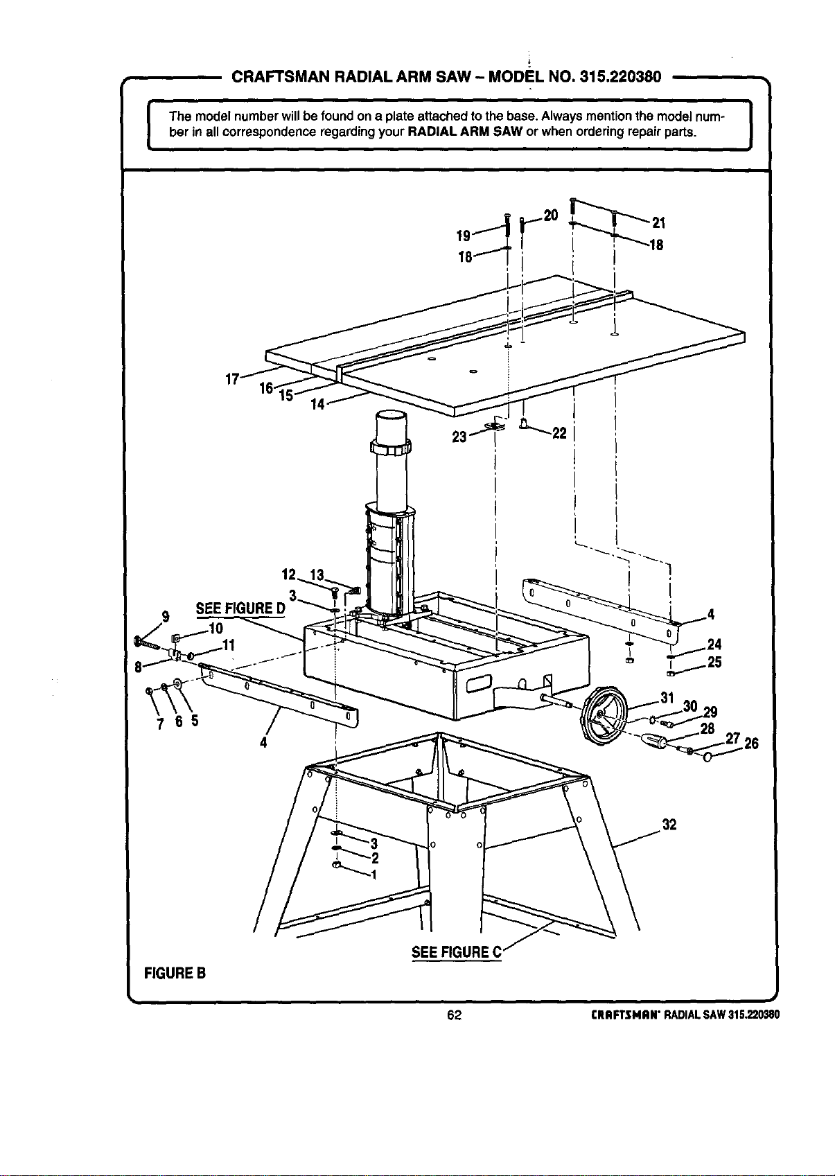
[
CRAFTSMAN RADIAL ARM SAW- MODEL NO. 315.220380
I
The modelnumberwillbe foundon a plate attachedtothe base. Alwaysmentionthe modelnum- |
her in all correspondenceregardingyour RADIAL ARM SAW or when orderingrepairparts.
I
9
SEE FIGL
32
FIGUREB
SEE FIGURE C
62 I:RAFTSMRN"RADIALSAW31S.220_80
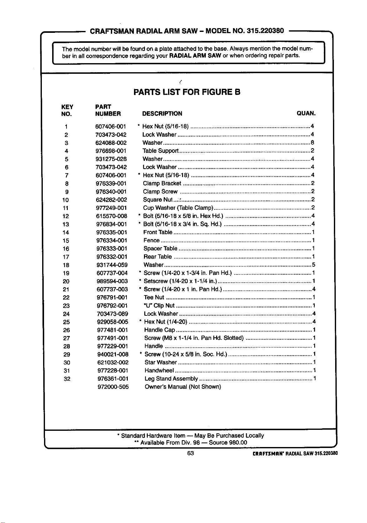
CRAFTSMAN RADIAL ARM SAW - MODEL NO. 315.220380
I The modelnumberwillbefoundon a plate attachedto the base,Always mentionthe modelnum- I
ber in all correspondenceregardingyourRADIAL ARM SAW orwhen orderingrepair parts.
I
PARTS LIST FOR FIGURE B
KEY PART
NO. NUMBER DESCRIPTION QUAN.
1 607406-001
2 703473-042
3 624088-002
4 976698-001
5 931275-028
6 703473-042
7 607406-001
8 976339-001
9 976340-001
10 624282-002
11 977249-001
12 615570-008
13 976834-001
14 976335-001
15 976334-001
16 976333-001
17 976332-001
18 931744-059
19 607737-004
20 989594-003
21 607737-003
22 976791-001
23 976792-001
24 703473-089
25 929058-005
26 977481-001
27 977491-001
28 977229-001
29 940021-008
30 621032-002
31 977228-001
32 976361-001
972000-505
* Hex Nut (5/16-18) .......................................................................... 4
Lock Washer .................................................................................. 4
Washer ........................................................................................... 8
Table Support ................................................................................. 2
Washer ........................................................................................... 4
Lock Washer .................................................................................. 4
* Hex Nut (5/16-18) .......................................................................... 4
Clamp Bracket ............................................................................... 2
Clamp Screw ................................................................................. 2
Square Nut..,' ................................................................................ 2
Cup Washer (Table Clamp) ............................................................ 2
* Bolt (5/16-18 x 5/8 in. Hex Hd.) ..................................................... 4
* Bolt (5/16-18 x 3/4 in. Sq, Hd.) ...................................................... 4
Front Table ..................................................................................... 1
Fence ............................................................................................. 1
Spacer Table .................................................................................. 1
Rear Table ..................................................................................... 1
Washer ........................................................................................... 5
* Screw (1/4-20 x 1-3/4 in. Pan Hd.) ................................................ 1
* Setscrew(1/4-20 x 1-1/4 in.).......................................................... 1
* Screw (1/4-20 x 1 in. Pan Hd.) ....................................................... 4
Tee Nut .......................................................................................... 1
"U" Clip Nut .................................................................................... 1
Lock Washer .................................................................................. 4
* Hex Nut (1/4-20) ............................................................................ 4
Handle Cap .................................................................................... 1
Screw (M8 x 1-1/4 in. Pan Hd. Slotted) ......................................... 1
Handle ........................................................................................... 1
* Screw (10-24 x 5/8 in. Soc. Hd.) .................................................... 1
Star Washer ................................................................................... 1
Handwheel ..................................................................................... 1
Leg Stand Assembly ...................................................................... 1
Owner's Manual (Not Shown)
* Standard Hardware Item-- May Be PurchasedLocally
** AvailableFromDiv, 98 -- Source980,00
63 CRRFTSMRH"RADIALSAW315.220380
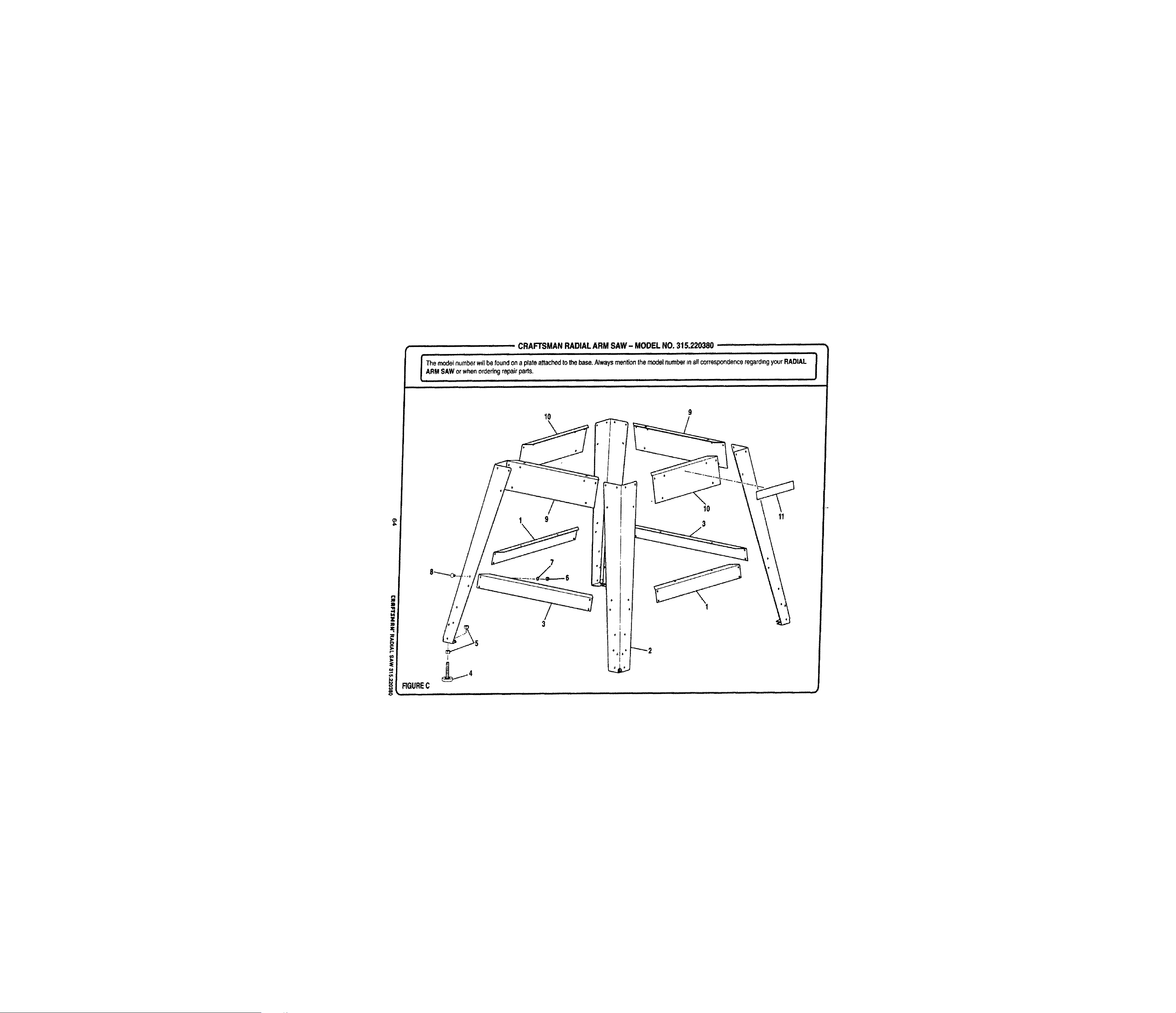
CRAFTSMAN RADIAL ARM SAW - MODEL NO. 315.220380 ...........
iqH i i iqHt rrr[[t r rl Illll I I Illl I[I
iT hemodelnumberwillbe foundona plateattac/'_:l to_e base.Alwaysmentionthemodelnumber_naF_correspondenceregardingyourRADIAL
I ARMSAW°r when°rderin9repairparts , ........ J
• i rrrrlnl Iqqr ]_l I II IJI I I I I H I
................ nnn i I II I Illl IIIm Ir IIImll
10
9
1 9
3
iqqqqml q i
10
3
I
rr iiiiir Iqqr
CRAFTSMAN RADIAL ARM SAW- MODEL NO. 315.220380
I The modelnumberwillbe foundon a plateattached tothebase. Always mentionthe modelnumberin all correspondenceregardingyour RADIAL |
|
ARM SAW or when orderingrepair parts.
I
o1
ol
PARTS LIST FOR FIGURE C
KEY PART
NO. NUMBER DESCRIPTION QUAN.
1 977242-001
2 976303-001
3 977241-001
4 976306-001
5 607406-005
6 929058-005
7 621032-010
8 977479-001
9 976304-001
10 976305-001
11 980659-001
976361-001
LowerFront/RearBrace.................................................................................................................................... 2
Leg ....................................................... ,............................................................,............................................... 4
LowerSide Brace .............................................................................................................................................. 2
LevelingFoot........:............................................................................................................................................. 4
Hex Nut (3/8-16) ................................................................................................................................................ 8
Hex Nut (1/4-20) .............................................................................................................................................. 40
StarWasher ................................................................................................................................................... 40
Screw(114-20x 518in.TrussHd.) ............................... :................................................................................... 40
Side Brace......................................................................................................................................................... 2
Front/RearBrace............................................................................................................................................... 2
LogoPlate ......................................................................................................................................................... 1
CompleteLeg StandAssembly(IncludesItemsListedAbove)
* Standard Hardware Item-- May Be PurchasedLocally
** AvailableFrom Div.98 -- Source 980.00
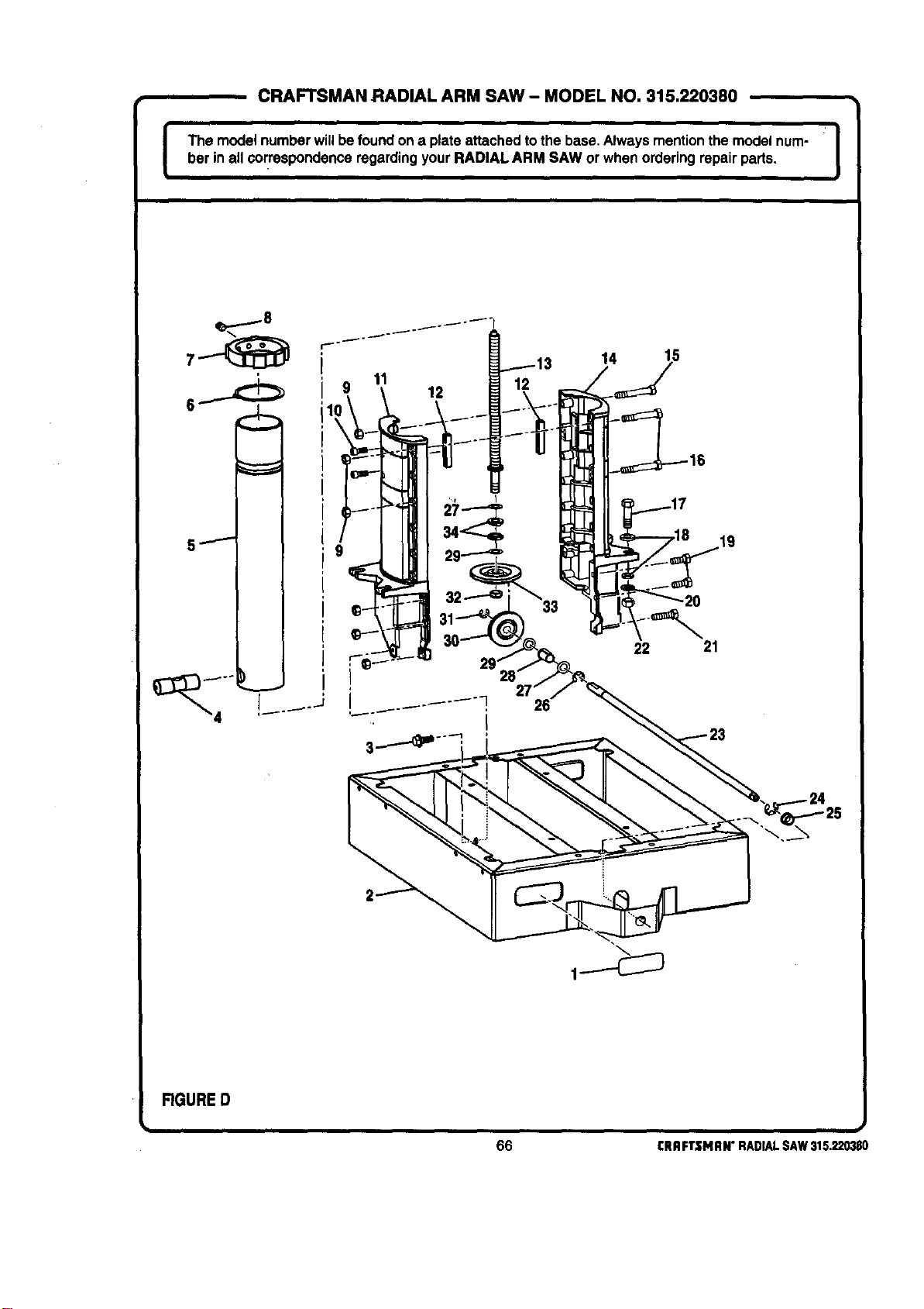
CRAFTSMAN RADIAL ARM SAW- MODEL NO. 315.220380
I •
i nu--w0efouo on , o--0o on ooo0on I
ber in all correspondence regardingyourRADIAL ARM SAW or when orderingrepair pads.
11
12
14 15
22
21
RGURED
_.,
66 CRRFTSMRN"RADIALSAW315.220380
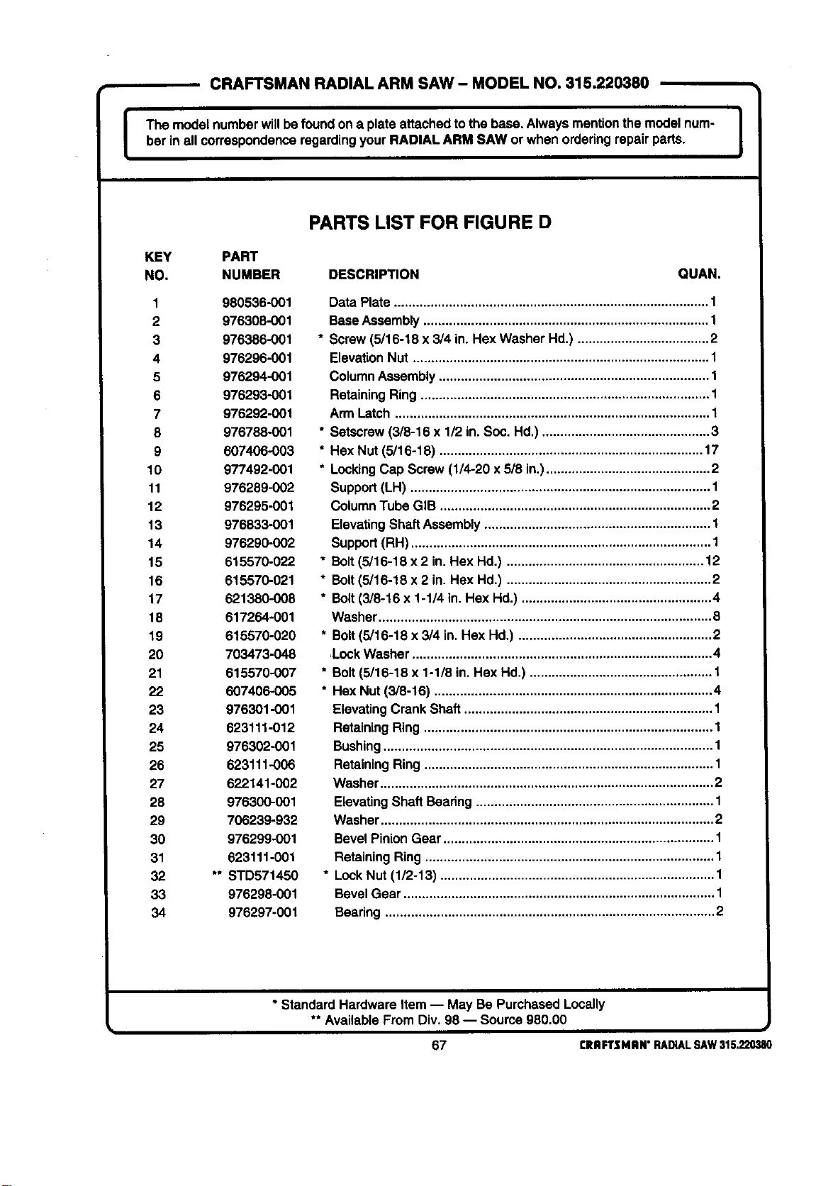
I
CRAFTSMAN RADIAL ARM SAW- MODEL NO, 315,220380
I
The modelnumberwillbefoundon a plateattached tothe base, Alwaysmentionthe model num-
her in all correspondenceregardingyour RADIAL ARM SAW or when orderingrepairparts.
I
PARTS LIST FOR FIGURE D
KEY PART
NO. NUMBER DESCRIPTION QUAN.
1 980536-001
2 976308-001
3 976386-001
4 976296-001
5 976294-001
6 976293-001
7 976292-001
8 976788-001
9 607406-003
10 977492-001
11 976289-002
12 976295-001
13 976833-001
14 976290-002
15 615570-022
16 615570-021
17 621380-008
18 617264-001
19 615570-020
20 703473-048
21 615570-007
22 607406-005
23 976301-001
24 623111-012
25 976302-001
26 623111-006
27 622141-002
28 976300-001
29 706239-932
30 976299-001
31 623111-001
32 " STD571450
33 976298-001
34 976297-001
Data Plate ...................................................................................... 1
Base Assembly .............................................................................. 1
* Screw (5/16-18 x 3/4 in. Hex Washer Hd.) .................................... 2
ElevationNut ................................................................................. 1
Column Assembly .......................................................................... 1
Retaining Ring ............................................................................... 1
Arm Latch ...................................................................................... 1
* Setscrew(3/8-16 x 1/2 in. Soc. Hd,) .............................................. 3
* Hex Nut (5/16-18) ........................................................................ 17
* Locking Cap Screw (1/4-20 x 5/8 in.)............................................. 2
Support(LH) .................................................................................. 1
Column Tube GIB .......................................................................... 2
ElevatingShaft Assembly .............................................................. 1
Support(RH) .................................................................................. 1
* Bolt (5/16-18 x 2 in. Hex Hd.) ...................................................... 12
* Bolt(3/16-18 x 2 in. Hex Hd.) ........................................................ 2
* Bolt(3/8-16 x 1-1/4 in. Hex Hd.) .................................................... 4
Washer ........................................................................................... 8
* Bolt (5/16-18 x 3/4 in. Hex Hd,) ..................................................... 2
,Lock Washer .................................................................................. 4
* Bolt (5/16-18 x 1-1/8 in. Hex Hd.) .................................................. 1
* Hex Nut (3/8-16) ............................................................................ 4
Elevating Crank Shaft.................................................................... 1
Retaining Ring ............................................................................... 1
Bushing .......................................................................................... 1
Retaining Ring ............................................................................... 1
Washer ........................................................................................... 2
ElevatingShaft Bearing ................................................................. 1
Washer ........................................................................................... 2
Bevel Pinion Gear .......................................................................... 1
Retaining Ring ............................................................................... 1
* Lock Nut (1/2-13) ........................................................................... 1
Bevel Gear ..................................................................................... 1
Bearing .......................................................................................... 2
* Standard Hardware Item -- May Be Purchased Locally
** AvailableFrom Div.98 -- Source980.00
67 CRAFTSMAN"RADIALSAW315.220380
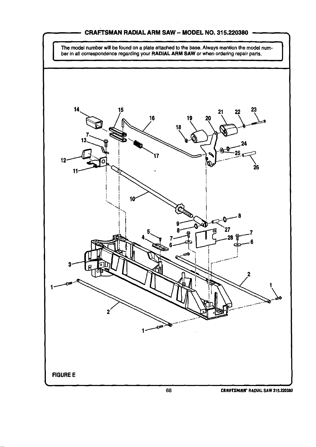
CRAFTSMAN RADIAL ARM SAW - MODEL NO. 315.220380
I The model numberwillbe foundon a plateattached tothe base. Alwaysmentionthe model num-
bar in all correspondenceregardingyourRADIAL ARM SAW or whenorderingrepair parts.
I
12'
15 21 22 23
16 19 20
18
\
26
FIGURE E
;i
68 £RAFTSMAN" RADIAL SAW 315,220380
I
CRAFTSMAN RADIAL ARM SAW- MODEL NO. 315.220380
The modelnumberwillbefoundon a plate attached tothe base.Always mentionthemodelnum-
ber in all correspondenceregardingyourRADIAL ARM SAW orwhen orderingrepair parts.
I
PARTS LIST FOR FIGURE E
KEY PART
NO. NUMBER DESCRIPTION QUAN.
1 622210-043
2 976323-001
3 976325-002
4 980613-001
5 611114-002
6 706382-834
7 980455-001
8 641180-005
9 976321-001
10 976804-001
11 976314-001
12 976312-001
13 976313-001
14 976310-001
15 976311-001
16 976315-001
17 976316-001
18 706405-002
19 976329-001
20 976827-001
21 976330-001
22 931055-006
23 606066-011
24 641180-006
25 931744-059
26 976319-001
27 976320-001
28 976322-001
* Screw(10-32 x 518in.Rd Hd.) ..................................................... 4
Track .............................................................................................. 2
Arm ........ , ......................................... .....** ................................. ***.,. 1
SupportBracket............................................................................. 1
* Screw (10-32 x 112in Flat Head T C) .......................................... 1
Washer........................................................................................... 2
* Screw (1/4-20 x 5/8 in SelfTappingHex Washer Hd) .................. 6
PushNut (3/8 in) ........................................................................... 2
Clevis Pin....................................................................................... 1
Arm Lock ROdAssembly................................................................ 1
Guide ............................................................................................. 1
Arm Lock Pawl............................................................................... 1
TensionSpring............................................................................... 1
Pin Housing ................................................................................... 1
Arm IndexPin ................................................................................ 2
Index ROd..................................................................................... 1
Arm LockSpring............................................................................ 1
* Hex Nut (10-32) ............................................................................. 1
Arm Knob Lever(Left Hand).......................................................... 1
Arm LockLever Assembly............................................................. 1
Arm Knob Lever(Right Hand) ....................................................... 1
Washer........................................................................................... 1
* Screw (10-32 x 2-1/4 in Pan Hd) ................................................. 1
PushNut (1/4 in) ........................................................................... 1
Washer...................................................................................... . 1
Lever Pin........................................................................................ 1
Pin.................................................................................................. 1
Arm Insulation................................................................................ 1
* Standard Hardware Item-- May Be PurchassdLocally
** AvailableFrom Div 98 -- Source980.00
69 CRRFTSHRN"RADIALSAW315.220380
I
, CRAFTSMAN RADIAL ARM SAW- MODEL NO. 315.220380
The modelnumberwillbefound ona plata attachedto the base. Alwaysmentionthemodelnum- I
bet in all correspondenceregardingyourRADIAL ARM SAW or when orderingrepair pads.
J
4
\
_ _ 21
20
I
30
3
22
31
FIGUREF
/
SEE FIGURE G
70 CRRFTSNRN"RADIALSAW315.220380
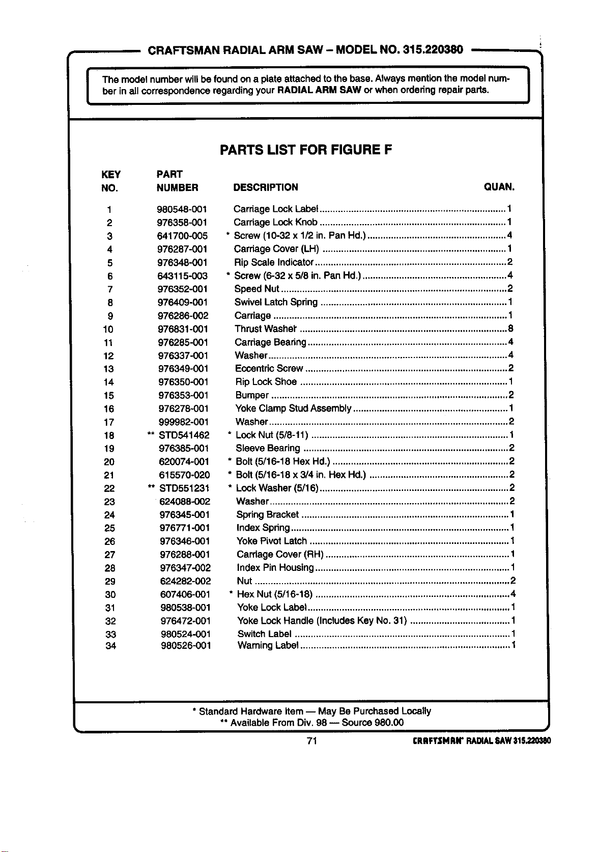
I
CRAFTSMAN RADIAL ARM SAW - MODEL NO, 315.220380
The model numberwillbefound on a plate attachedtothe base. Always mentionthe model nurn- J
ber in allcorrespondenceregardingyourRAOIAL ARM SAW or when ordedng repairparts.
I
PARTS LIST FOR FIGURE F
KEY PART
NO. NUMBER DESCRIPTION QUAN.
1 980548-001
2 976358-001
3 641700-005
4 976287-001
5 976348-001
6 643115-003
7 976352-001
8 976409-001
9 976286-002
10 976831-001
11 976285-001
12 976337-001
13 976349-001
14 976350-001
15 976353-001
16 976278-001
17 999982-001
18 ** STD541462
19 976385-001
20 620074-001
21 615570-020
22 ** STD551231
23 624088-002
24 976345-001
25 976771-001
26 976346-001
27 976288-001
28 976347-002
29 624282-002
30 607406-001
31 980538-001
32 976472-001
33 980524-001
34 980526-001
Carriage LockLabe!....................................................................... 1
Cardage Lock Knob ....................................................................... 1
* Screw(10-32 x 1/2 in. Pan Hd.) ..................................................... 4
Cardage Cover (LH) ...................................................................... 1
Rip Scale Indicator......................................................................... 2
* Screw (6-32 x 5/8 in. Pan Hd.) ....................................................... 4
Speed Nut ...................................................................................... 2
Swivel Latch Spdng ....................................................................... 1
Carriage ......................................................................................... 1
Thrust Washer"............................................................................... 8
Cardage Bearing ............................................................................ 4
Washer ........................................................................................... 4
Eccentdc Screw............................................................................. 2
Rip Lock Shoe ............................................................................... 1
Bumper .......................................................................................... 2
Yoke Clamp StudAssembly ........................................................... 1
Washer ........................................................................................... 2
* Lock Nut (5/8-11) ........................................................................... 1
Sleeve Beadng .............................................................................. 2
* Bolt (5/16-18 Hex Hd.) ................................................................... 2
* Bolt (5/16-18 x 3/4 in. Hex Hd.) ..................................................... 2
* Lock Washer (5/16)........................................................................ 2
Washer ........................................................................................... 2
SpringBracket ............................................................................... 1
Index Spdng................................................................................... 1
Yoke Pivot Latch ............................................................................ 1
Carriage Cover (RH) ...................................................................... 1
Index Pin Housing .......................................................................... 1
Nut ................................................................................................. 2
* Hex Nut (5/16-18) .......................................................................... 4
Yoke Lock Label............................................................................. 1
Yoke Lock Handle (Includes Key No. 31) ...................................... 1
SwitchLabel .................................................................................. 1
Warning Label ................................................................................ 1
* Standard Hardware Item -- May Be PurchasedLocally
** AvailableFrom Div. 98 -- Source980.00
i
71 CRflFTSMRN"RADIALSAW31S.220_180
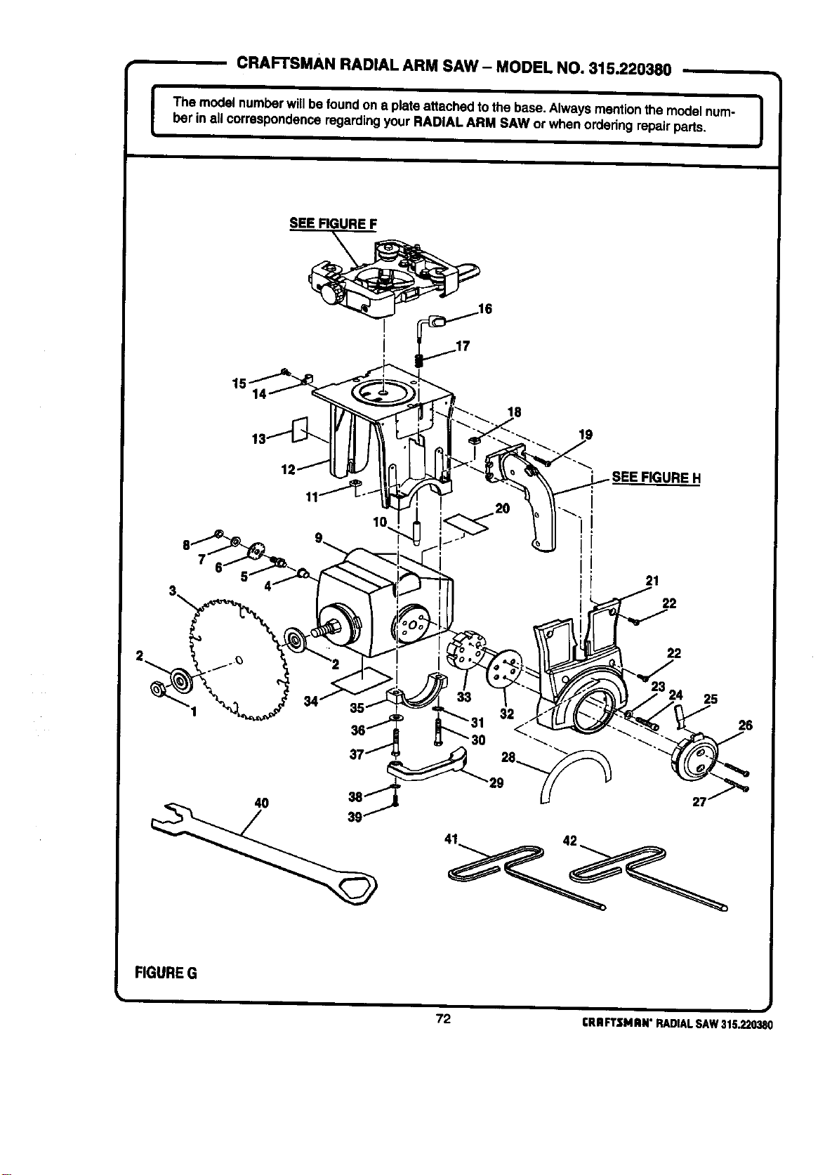
[
CRAFTSMAN RADIAL ARM SAW - MODEL NO. 315.220380
The modelnumberwillbe foundon a plate attachedto the base.Always mentionthe modelnum-
ber in all correspondenceregardin9 your RADIAL ARM SAW or when orderingrepairparts.
I
SEE FIGURE F
15-
10
18
SEE FIGURE H
i,
i,
I 21
22
25
37 28_
40
26
FIGUREG
72 rRRFTSMRN"RADIALSAW315.220380
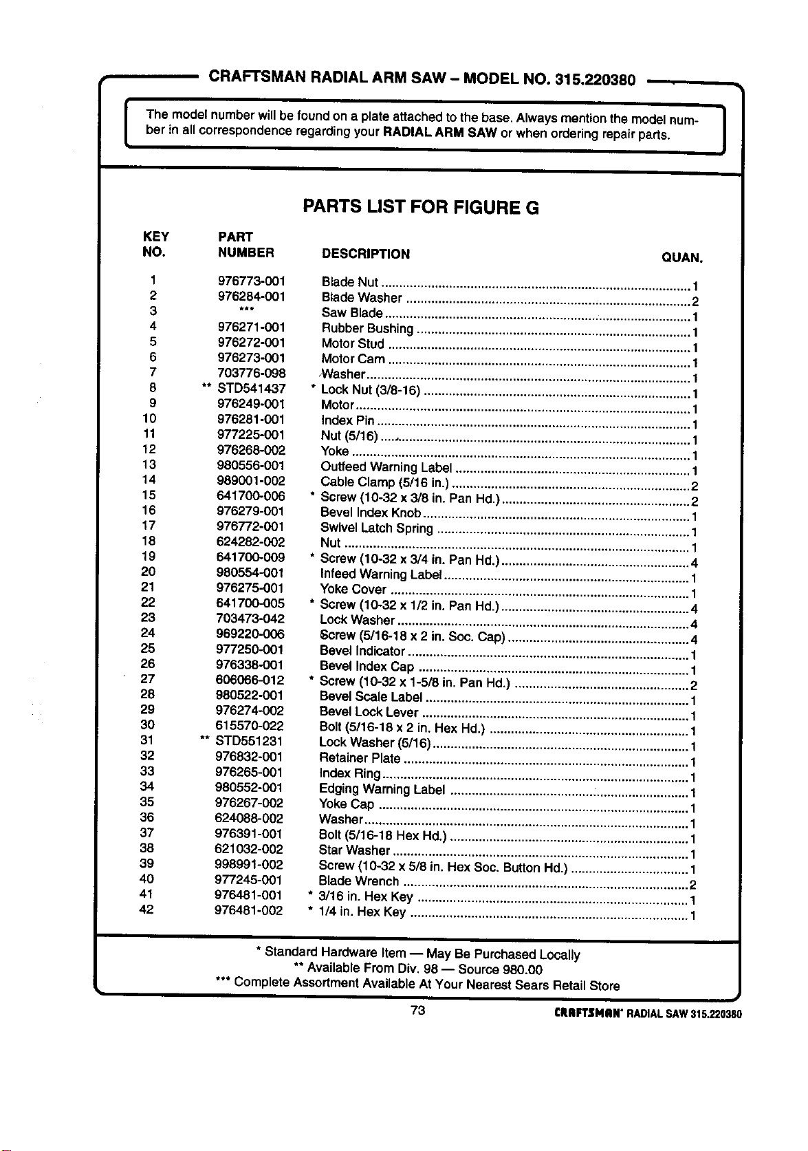
I
CRAFTSMAN RADIAL ARM SAW - MODEL NO. 315.220380
The model numberwillbe foundon a plate attachedto the base.Always mentionthemodelnum-
ber in all correspondenceregardingyour RADIAL ARM SAW or when orderingrepair parts.
]
PARTS LIST FOR FIGURE G
KEY PART
NO. NUMBER DESCRIPTION QUAN,
1 976773-001
2 976284-001
3 ***
4 976271-001
5 976272-001
6 976273-001
7 703776-098
8 ** STD541437
9 976249-001
10 976281-001
11 977225-001
12 976268-002
13 980556-001
14 989001-002
15 641700-006
16 976279-001
17 976772-001
18 624282-002
19 641700-009
20 980554-001
21 976275-001
22 641700-005
23 703473-042
24 969220-006
25 97/250-001
26 976338-001
27 606066-012
28 980522-001
29 976274-002
30 615570-022
31 ** STD551231
32 976832-001
33 976265-001
34 980552-001
35 976267-002
36 624088-002
37 976391-001
38 621032-002
39 998991-002
46 977245-001
41 976481-001
42 976481-002
Blade Nut ....................................................................................... 1
BladeWasher ................................................................................ 2
Saw Blade...................................................................................... 1
RubberBushing............................................................................. 1
MotorStud ..................................................................................... 1
MotorCam ..................................................................................... 1
NVasher........................................................................................... 1
* Lock Nut (3/8-16) ........................................................................... 1
Motor.............................................................................................. 1
index Pin........................................................................................ 1
Nut (5/16) ....................................................................................... 1
Yoke............................................................................................... 1
Outfeed WarningLabel.................................................................. 1
Cable Clamp (5/16 in.)................................................................... 2
* Screw (10-32 x 3/8 in. Pan Hd.)..................................................... 2
Bevel index Knob........................................................................... 1
Swivel Latch Spring....................................................................... 1
Nut ................................................................................................. 1
* Screw(10-32 x 3/4 in. Pan Hd.) ..................................................... 4
Infeed Warning Labe! ..................................................................... 1
Yoke Cover .................................................................................... 1
* Screw (10-32 x 1/2 in, Pan Hd.) ..................................................... 4
LockWasher .................................................................................. 4
Screw (5/16-18 x 2 in. Soc. Cap) ................................................... 4
Bevel Indicator ............................................................................... 1
Bevel Index Cap ............................................................................ 1
* Screw (10-32 x 1-5/8 in. Pan Hd,) ................................................. 2
Bevel Scale Label .......................................................................... 1
Bevel Lock Lever ........................................................................... 1
Bolt (5/16-18 x 2 in. Hex Hd.) ........................................................ 1
Lock Washer (5/16) ........................................................................ 1
Retainer Plate ................................................................................ 1
Index Ring ...................................................................................... 1
Edging Warning Label ................................................................... 1
Yoke Cap ....................................................................................... 1
Washer ........................................................................................... 1
Bolt (5/16-18 Hex Hd.) ................................................................... 1
StarWasher ................................................................................... 1
Screw (10-32 x 5/8 in. Hex Soc. Button Hd.) ................................. 1
BladeWrench ................................................................................ 2
* 3/16 in. Hex Key ............................................................................ 1
* 1/4 in. Hex Key .............................................................................. 1
* Standard Hardware Item -- May Be PurchasedLocally
** AvailableFrom Div, 98 -- Source 980.00
*** Complete AssortmentAvailable AtYour Nearest Sears Retail Store
J
73 rRIIFTSNilN"RADIALSAW315.220380
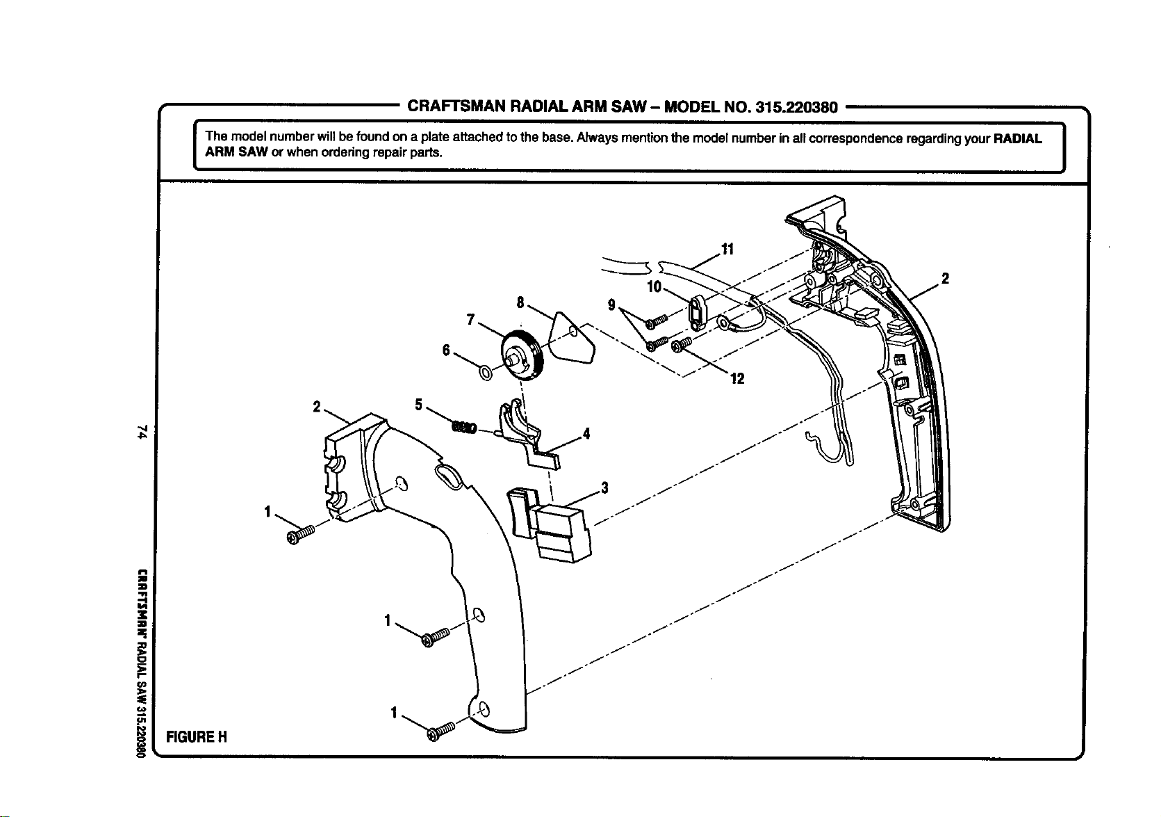
CRAFTSMAN RADIAL ARM SAW- MODEL NO. 315.220380
I The modelnumberwillbefoundon a plateattached tothe base. Alwaysmentionthe modelnumberin all correspondenceregardingyourRADIAL |
|
ARM SAW or when orderingrepair parts.
I
4=
i FIGURE H
12
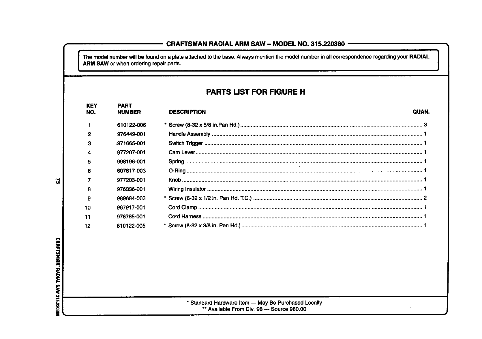
CRAFTSMANRADIALARMSAW- MODELNO.315.220380
The modelnumberwillbe foundon a plate attachedtothe base. Alwaysmentionthe modelnumberin all correspondenceregardingyourRADIAL |
ARM SAW orwhen orderingrepairparts.
I
PARTS LIST FOR FIGURE H
KEY PART
NO. NUMBER DESCRIPTION QUAN.
1 610122-006
2 976449-001
3 _971665-001
4 977207-001
5 998196-001
6 607617-003
7 977203-001
8 976336-001
9 989684-003
10 967917-001
11 976785-001
12 610122-005
* Screw(6-32 x 5/8 in.Pan Hd.).......................................................................................................................... 3
HandleAssembly... ......................................................................................................................................... 1
SwitchTrigger.................................................................................................................................................. 1
Cam Lever........................................................................................................................................................ 1
Spring............................................................................................................................................................... 1
O-Ring .............................................................................................................................................................. 1
Knob................................................................................................................................................................. 1
Wiring Insulator................................................................................................................................................ 1
* Screw(6-32 x 1/2 in. Pan Hd. T.C.) ................................................................................................................. 2
Cord Clamp ...................................................................................................................................................... 1
Cord Harness ................................................................................................................................................... 1
* Screw (8-32 x 3/8 in. Pan Hd.)......................................................................................................................... 1
* Standard HardwareItem -- May Be Purchased Locally
** AvailableFrom Div.98 -- Source 980.00
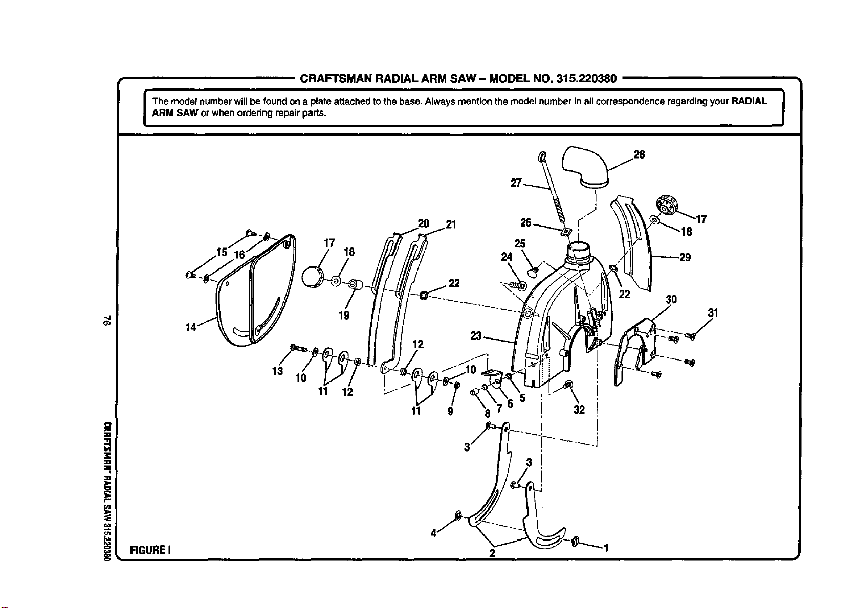
CRAFTSMAN RADIAL ARM SAW- MODEL NO. 315.220380
The modelnumberwillbe foundon a plate attachedtothe base, Alwaysmentionthemodel number inall correspondenceregardingyourRADIAL |
i
ARM SAW or whenorderingrepairparts.
J
_4
O_
z
zl
=,
:O
o
€O
t,n
FIGUREI
13
10
17 25
18
11
3O
31
19 ._
11 9
8
3
32
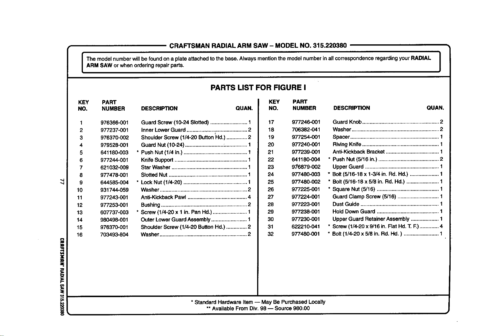
CRAFTSMANRADIALARMSAW- MODELNO.315.220380
The modelnumberwillbe foundona plate attachedtothe base. Alwaysmentionthe modelnumber inall correspondenceregardingyourRADIAL I
I
ARM SAW or when orderingrepairparts.
J
PARTS LIST FOR FIGURE I
i
z
D
=,
;Ib
r-
=
!
KEY PART
NO. NUMBER DESCRIPTION QUAN.
1 976366-001
2 977237-001
3 976370-002
4 979528-001
5 641180-003
6 977244-001
7 621032-009
8 977478-001
9 644585-004
10 931744-069
11 977243-001
12 977253-001
13 607737-003
14 980498-001
15 976370-001
16 7O3493-804
Guard Screw(10-24 Slotted)......................... 1
inner LowerGuard......................................... 2
ShoulderScrew (1/4-20 ButtonHd.) .............. 2
GuardNut (10-24) ..........................:............... 1
* Push Nut(1/4 in.)........................................... 1
KnifeSupport................................................. 1
StarWasher................................................... 1
SlottedNut ..................................................... 1
* LockNut (1/4-20) ........................................... 1
Washer........................................................... 2
Anti-KickbackPawl ........................................ 4
Bushing.......................................................... 2
* Screw (1/4-20 x 1 in.Pan Hd.)....................... 1
Outer LowerGuardAssembly........................ 1
ShoulderScrew(1/4-20 ButtonHd.).............. 2
Washer........................................................... 2
KEY PART
NO. NUMBER DESCRIPTION QUAN.
17 977246-001
18 706382-041
19 977254-001
20 977240-001
21 977239-001
22 641180-004
23 9/6879-002
24 977480-003
25 977480-002
26 977225-001
27 977224-001
28 977223-001
29 977238-001
30 977230-001
31 622210-041
32 977480-001
* Standard Hardware Item-- May Be PurchasedLocally
** AvailableFromDiv.98 -- Soume 980.00
Guard Knob.................................................... 2
Washer........................................................... 2
Spacer............................................................ 1
RivingKnife.................................................... 1
Anti-KickbackBracket.................................... 1
* Push Nut (5/16 in.)......................................... 2
Upper Guard .................................................. 1
* Bolt(5/16-18 x 1-3/4 in. Rd.Hd.) .................... 1
* Bolt(5/16-18 x 5/8 in.Rd. Hd.) ...................... 1
* Square Nut (6/16) .......................................... 1
GuardClamp Screw(5/16) ............................ 1
DustGuide ..................................................... 1
HoldDown Guard .......................................... 1
Upper GuardRetainerAssembly................... 1
* Screw(1/4-20x 9/16in. Flat Hd.T. F.)............. 4
* Bolt(1/4-20 x 5/8 in.Rd. Hd.) ........................ 1
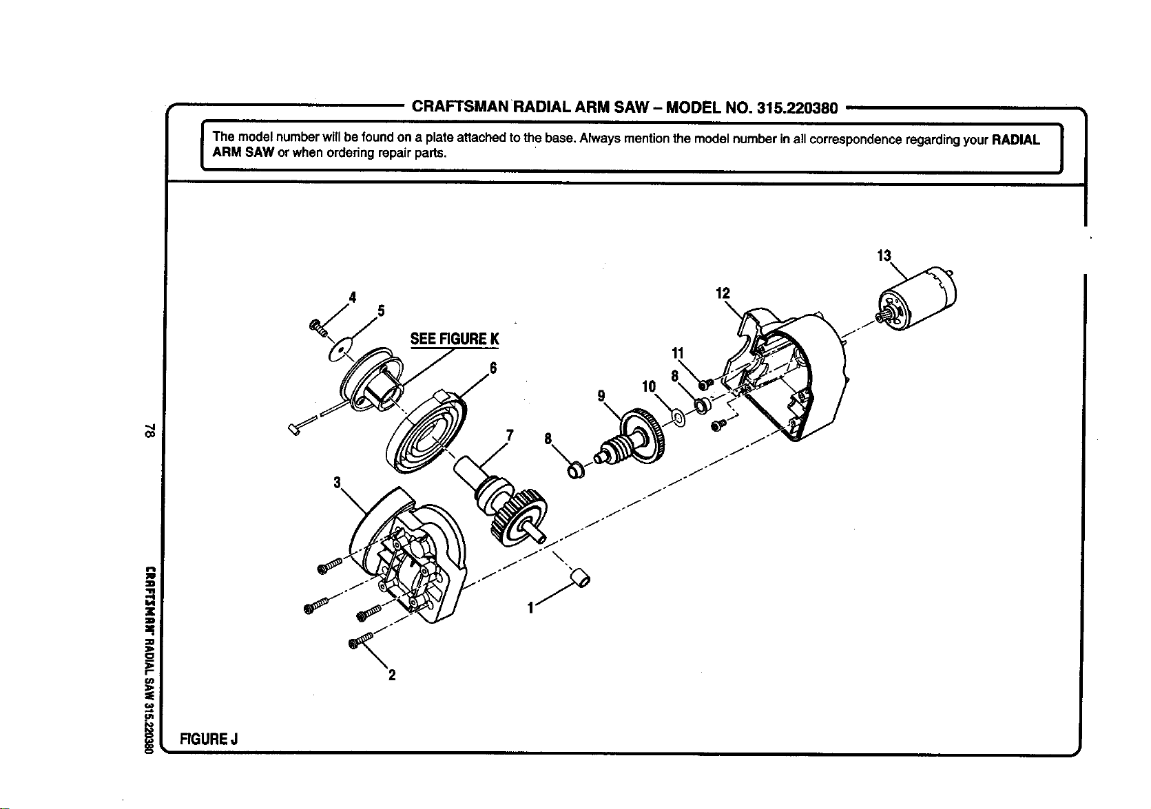
CRAFTSMAN RADIAL ARM SAW - MODEL NO. 315.220380
I The modelnumberwillbe foundon a plateattachedto the base.Always mentionthe modelnumberin allcorrespondenceregardingyourRADIAL |
ARM SAW or when orderingrepair parts.
I
Co
RGUREJ
SEERGUREK
7
10
9
X
11
12
13
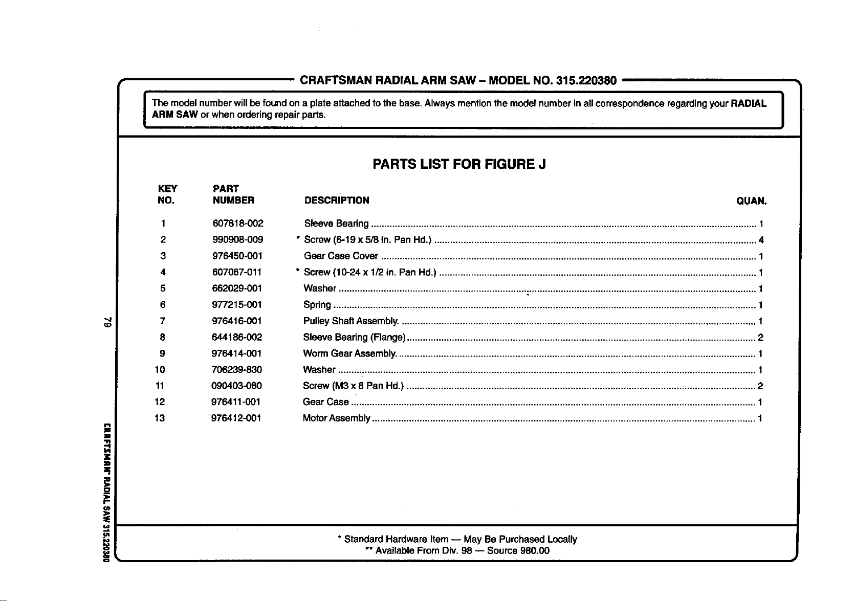
CRAFTSMANRADIALARMSAW- MODELNO.315.220380
I The modelnumberwillbefoundon a plateattached to the base.Always mentionthe modelnumberin all correspondenceregardingyourRADIAL |
i
ARM SAW orwhen orderingrepair parts.
I
CD
(/)
=.
==,
PARTS LIST FOR FIGURE J
KEY PART
NO. NUMBER DESCRIPTION QUAN.
1 607818-002
2 990908-009
3 976450-001
4 607067-011
5 662029-001
6 977215-001
7 976416-001
8 644186-002
9 976414-001
10 706239-830
11 090403-080
12 976411-001
13 976412-001
Sleeve Beadng.................................................................................................................................................. 1
* Screw(6-19 x 5/8 In. Pan Hd.) .......................................................................................................................... 4
Gear Case Cover .............................................................................................................................................. 1
* Screw(10-24 x 1/2 in. Pan Hd.) ........................................................................................................................ 1
Washer .............................................................................................................................................................. 1
Spring................................................................................................................................................................ 1
PulleyShaftAssembly....................................................................................................................................... 1
Sleeve Bearing(Flange).................................................................................................................................... 2
WormGear Assembly........................................................................................................................................ 1
Washer.............................................................................................................................................................. t
Screw(M3 x 8 Pan Hd.) .................................................................................................................................... 2
Gear Case ......................................................................................................................................................... 1
MotorAssembly................................................................................................................................................. 1
* Standard Hardware Item-- May Be Purchased Locally
** AvailableFrom Div. 98 -- Soume 980.00
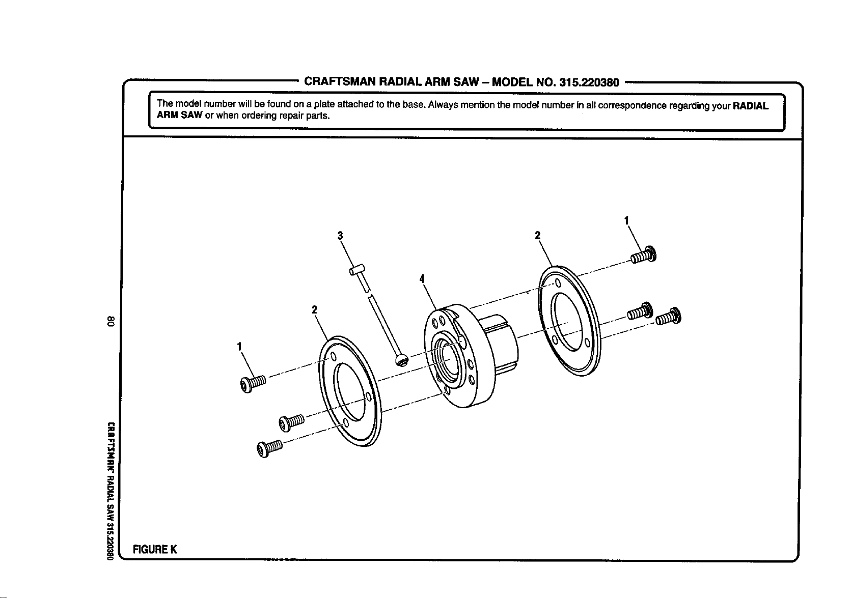
CRAFTSMAN RADIAL ARM SAW - MODEL NO. 315.220380
I The modelnumberwillbe foundona plate attachedtothe base. Alwaysmentionthe modelnumberinall correspondenceregardingyourRADIAL I
ARM SAW or when orderingrepairparts.
I
o=
.=
==
_O
_2
I"
o1
i
RGUREK
1
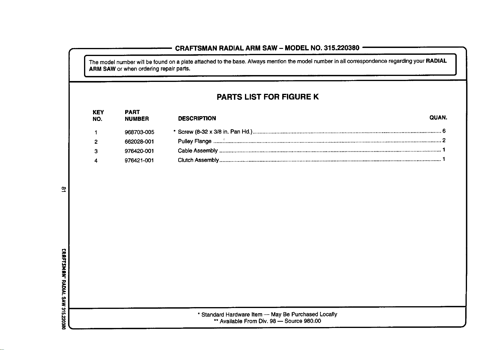
CRAFTSMANRADIALARMSAW- MODELNO.315.220380
The modelnumber willbe foundon a plate attachedto thebase. Alwaysmentionthe model numberinall correspondenceregarding yourRADIAL
ARM SAW or when orderingrepairparts.
PARTS LIST FOR FIGURE K
KEY PART
NO. NUMBER DESCRIPTION QUAN.
1
2
3
4
968703-005
662028-001
976420-001
976421-001
* Screw (8-32 x 3/8 in. Pan Hd.).......................................................................................................................... 6
PulleyFlange ......."............................................................................................................................................. 2
CableAssembly................................................................................................................................................ 1
ClutchAssembly................................................................................................................................................ 1
=_,
i
* Standard Hardware Item-- May Be PurchasedLocally
** AvailableFrom Div.98 -- Source 980.00

For in-home major brand repair service:
Call 24 hours a day, 7 days a week
1-800-4-MY-HOME s" (1-800-469-4663)
Para pedir servicio de reparacibn a domicilio - 1-800-676-5811
In Canada for all your service and parts needs call
- 1-800-665-4455
Au Canada pour tout le service ou les pi_ces
For the repair or replacement parts you need:
Call 6 am - 11 pm CST, 7 days a week
PartsDirect sM
1-800-366-PART (1-800-366-7278)
Para ordenar piezas con entrega a domicilio - 1-800-659-7084
For the location of a Sears Parts and Repair Center in your area:
Call 24 hours a day, 7 days a week
1-800-488-1222
For information on purchasing a Sears Maintenance Agreement
or to inquire about an existing Agreement:
Call 9 am - 5 pm, Monday - Saturday
1-800-827-6655
HomeCentrals"
The Service Side of Sears