Loading ...
Loading ...
Loading ...
LEVELING THE TABLE SUPPORTS
See Figures 22,4 and 22B.
The table supportsmustbe perfectlylevel.
• Pullthe bevel locklever forwardtounlockit. Use
the bevel indexknobto rotatethemotorso the
arborshaft pointsdown. Lockthe bevel lock lever.
• Release the arm lockknobtoangle thearm. Begin
bypositioningthe arborshaftover the backof the
highesttable support.Normallythis isthe leftside.
See Figure 22,4.
• Lockthe arm lockknoband thecardage lockknob.
• Usingone of the bladewrenchesas a feeler gage,
place iton thetable supportbelowthearbor shaft.
• Withthe elevating handwheel,carefullylowerthe
motoruntilthe shaftjust touchesthe wrench.The
wrenchshouldmovewithonlyslightresistance.
Securelytightenthe backscrewon the table
support.
i Withoutchangingthe elevation,movethearm to
place the bladearbor over thefrontoftable sup- '
port. See Figure22B.
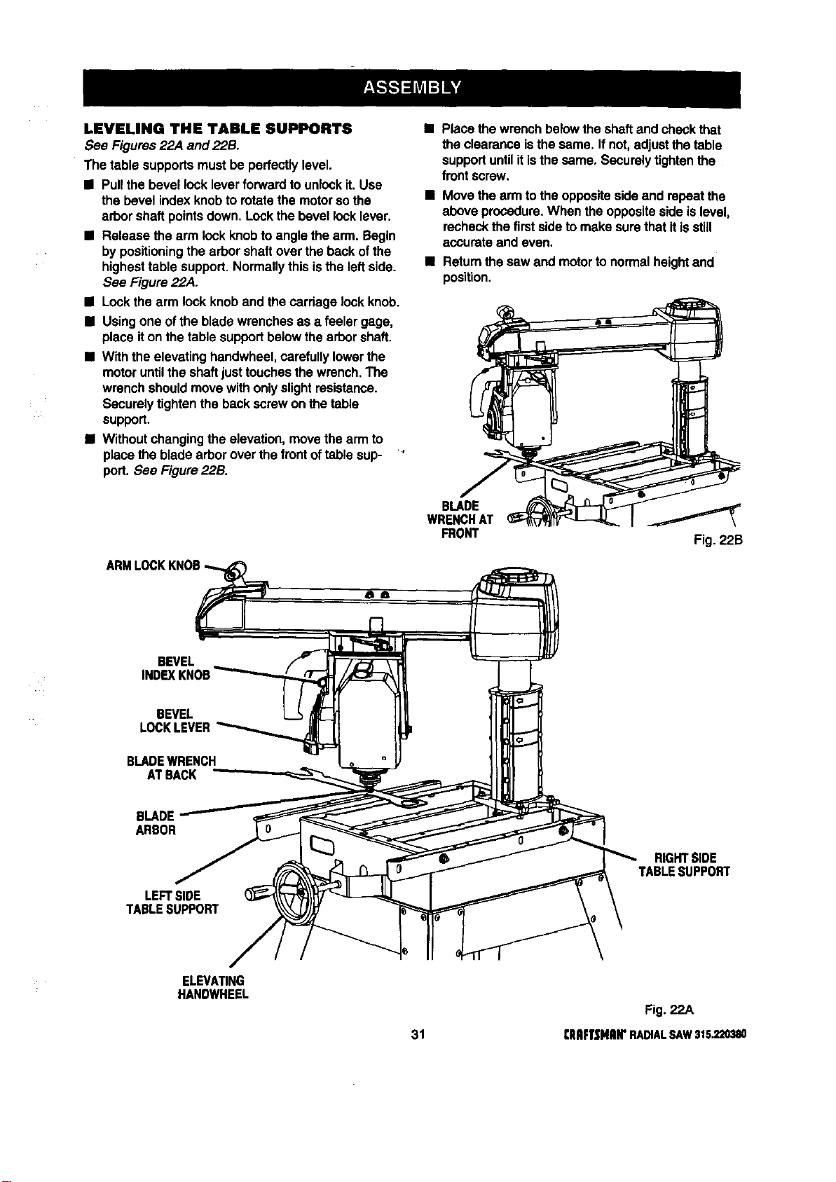
Place thewrenchbelowthe shaftand checkthat
the clearanceisthesame. Ifnot,adjustthe table
supportuntilitisthe same, Securelytightenthe
frontscrew,
• Movethe arm tothe oppositeside and repeat the
above procedure.When the oppositeside islevel,
recheckthe firstsideto make surethat itisstill
accurate and even.
• Returnthesaw and motortonormalheightand
position.
BLADE
WRENCHAT
FRONT Fig. 22B
BEVEL
INDEXKNOB
BEVEL
LOCKLEVER
BLADEWRENCH
ATBACK
BLADE
ARBOR
LEFTSIDE
TABLESUPPORT
RIGHTSIDE
TABLESUPPORT
ELEVATING
HANDWHEEL
Fig. 22A
31 [IIRFTSHRII"RADIALSAW315.220380
Loading ...
Loading ...
Loading ...