Loading ...
Loading ...
Loading ...
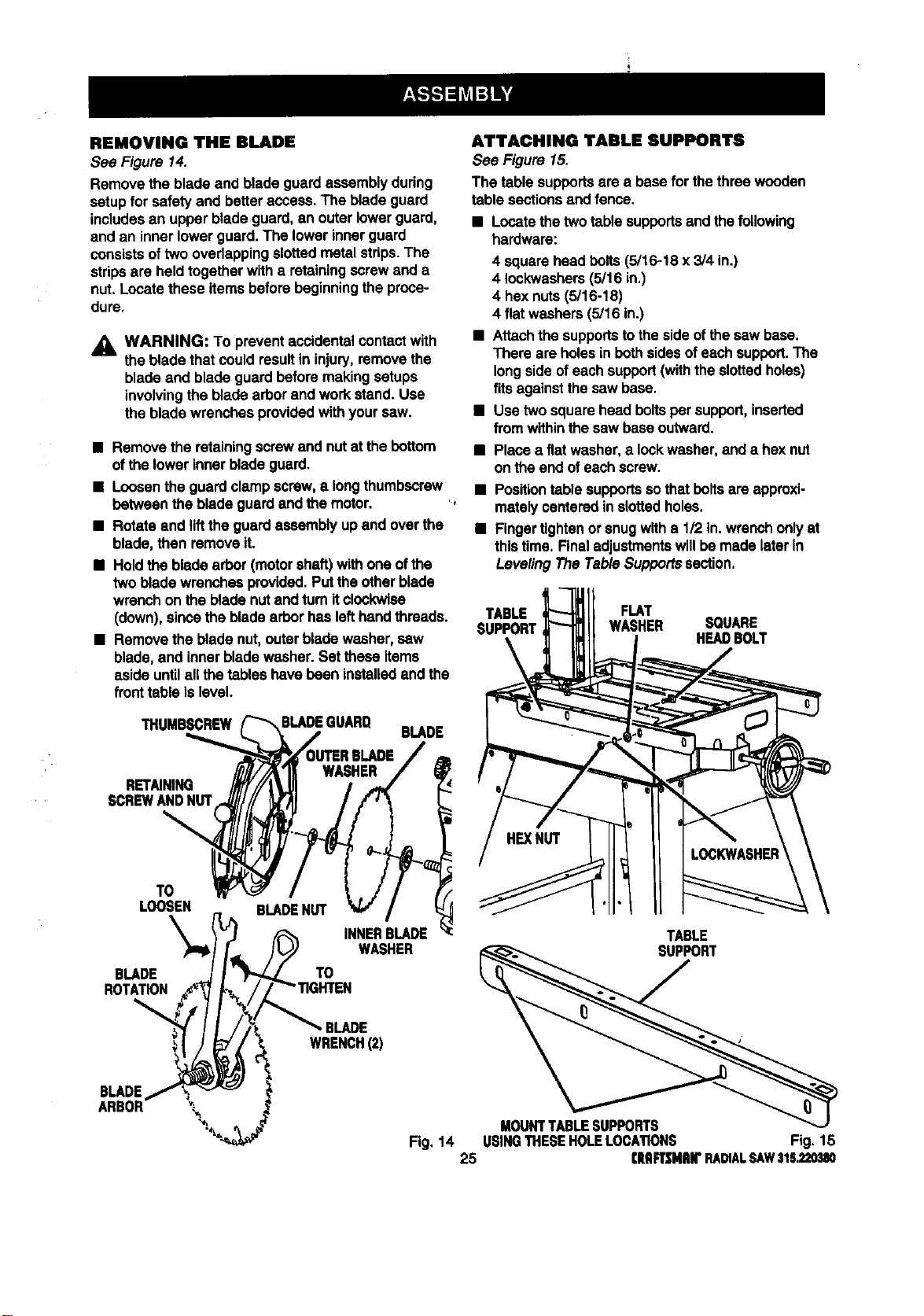
REMOVING THE BLADE
See Figure 14.
Remove the blade and blade guard assemblyduring
setupfor safety and betteraccess.The blade guard
includesan upper bladeguard,an outerlowerguard,
and an inner lowerguard. The lowerinnerguard
consistsoftwo overlappingslottedmetalstrips.The
stripsare heldtogetherwith a retainingscrewand a
nut. Locatethese itemsbeforebeginningthe proce-
dure.
_i, WARNING: To preventaccidentalcontactwith
the bladethat couldresultin injury,remove the
blade and blade guard beforemakingsetups
involvingthe bladearbor and workstand. Use
the bladewrenches providedwithyour saw.
• Remove the retainingscrew and nut at thebottom
ofthe lowerinnerblade guard.
• Loosenthe guardclamp screw,a longthumbscrew
between the bladeguard andthe motor.
• Rotateand liftthe guardassembly up and overthe
blade, then remove it.
• Holdthe blade arbor (motorshaft) withone ofthe
two bladewrenchesprovided.Putthe otherblade
wrenchonthe blade nutand turnit clockwise
(down), sincethe bladearborhas lefthandthreads.
• Remove the bladenut,outerbladewasher, saw
blade, and innerbladewasher.Set these Items
aside untilall thetables have bean installedand the
fronttable islevel.
THUMBSCREW
BLADE
RETAINING
SCREWANDNUT
TO
LOOSEN
\
BLADE
ROTATION
BLADENUT
TO
INNERBLADE
WASHER
BLADE
WRENCH(2)
BLADE
ARBOR _'_
ATTACHING TABLE SUPPORTS
See Figure 15.
The table supportsare a basefor the three wooden
table sectionsand fence.
• Locatethetwo table supportsand thefollowing
hardware:
4 squarehead bolts(5/16-18 x 3/4 in.)
4 Iockwashers(5/16 in.)
4 hexnuts (5/16-18)
4 flat washers(5/16 in.)
• Attachthe supportstotheside ofthesaw base.
There are holesin bothsidesof eachsupport.The
longsideofeach support(withthe slottedholes)
fitsagainstthesaw base.
B Use two squarehead boltsper support,inserted
from withinthe saw baseoutward.
• Place a fiatwasher,a lockwasher,and a hex nut
on the end ofeachscrew.
• Positiontable supportsso thatboltsare approxi-
matelycenteredin slottedholes.
• Fingertightenorsnugwitha 1/2 in.wrenchonlyat
thistime. Finaladjustmentswillbemade later in
LevelingThe Table Supportssection.
TABLE FLAT
SUPPORT WASHER SQUARE
HEAl)BOLT
TABLE
SUPPORT
MOUNTTABLESUPPORTS
Fig, 14 USINGTHESEHOLELOCATIONS Fig. 1B
25 rltRFTSNRB"RADIALSAW315.220_I0
Loading ...
Loading ...
Loading ...