Home
Search
Bookmarks
Write Review
ManualsFile
Craftsman
Craftsman User Manuals
Find
Tip search: Enter brand name + model number to search. For example:
Craftsman 893MAX
How to find model number?
Newly added products
893MAX 2 for Chamberlain Craftsman LiftMaster Garage Door Opener Remote, Replaces 893LM 891LM 371LM 373LM 971LM 973LM, no Wait Wireless Remote Keyless Entry, Safe Security
2026-07-01
1 docs
SOUSKY Mini Chainsaw Cordless, 6Inch Portable Small Chain Saw Battery Powered, Handheld Chainsaws with 2 * 24V 2.0MAH Powered Rechargeable Battery for Tree/Wood Cutting Trimming Craftsman Gardening Pruning
2026-05-26
1 docs
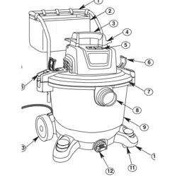
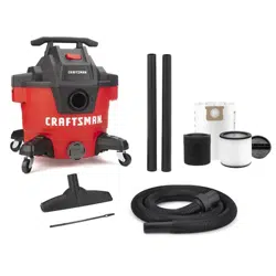
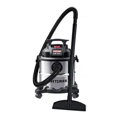
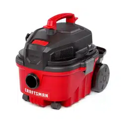
CMXEVBE18690 CRAFTSMAN 9 Gallon 4.25 Peak HP Wet Dry Vac, Portable Shop Vacuum Wet and Dry with Filter, Dust Bag, Dusting Brush, Hose and Attachments for Home, Garage and Automotive Cleaning
2026-05-25
1 docs
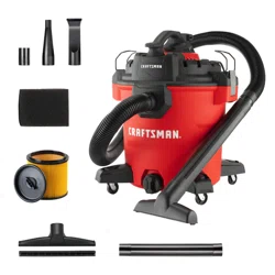
CMXEVBE18595 CRAFTSMAN 16 Gallon 6.5 Peak HP Wet Dry Vac, Heavy-Duty Shop Vacuum Wet and Dry with Filter, 4 Dust Bags, Hose and Attachments for Home Projects & Renovations
2026-05-25
1 docs
CMXEVBE18590 CRAFTSMAN 9 Gallon 4.25 Peak HP Wet Dry Vac, Portable Shop Vacuum Wet and Dry with Filter, 3 Dust Bags, Hose and Attachments for Home, Garage and Automotive Cleaning
2026-05-25
1 docs
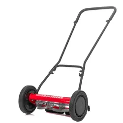
Craftsman CMXRMLM141516 16-in 5 Reel Lawn Mower
2026-04-15
1 docs
Craftsman CMCMWP120M2 Push Mower 15 in
2026-04-09
1 docs
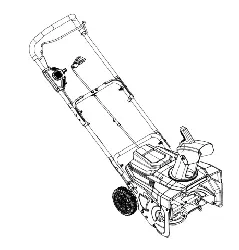
Craftsman A082029 DC Snow Blower
2026-02-23
1 docs
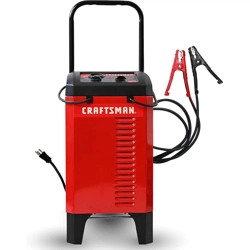
CRAFTSMAN CMXCESM274 Wheeled Manual 6A Car Battery Charger and 175A Engine Starter, 25A Boost
2026-01-15
1 docs
Craftsman CMXEVBE176560 20 Gallon 75L Wet/Dry Vac
2026-01-14
1 docs
Craftsman CMXEVBE176120 4 Gallon Portable Wet/Dry Vac
2026-01-14
1 docs
Craftsman CMXEVBE17040 Corded 4-Gallon 5.0 Peak HP Electic Wet/Dry Shop Vac
2026-01-14
1 docs
Craftsman CMXEVBCV945L 9-Gallon 4.5 HP Corded Wet/Dry Vacuum
2026-01-14
1 docs
Craftsman CMXEVBCV1260L 12-Gallon 6 HP Corded Wet/Dry Shop Vacuum
2026-01-14
1 docs
Craftsman CMXEVBE179250 5 Gallon Wet/Dry Vac
2026-01-14
1 docs
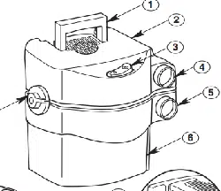
Craftsman 81998 Professional Wide Range Infrared Thermometer
2026-01-05
1 docs
Craftsman 50455 Mini Infrared Thermometer 500 Degree Laser
2026-01-05
1 docs
Craftsman CMCD714D1 20V Max 1/2" Keyless Brushless Cordless Drill
2025-12-30
1 docs
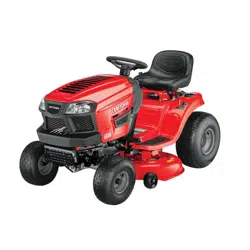
Craftsman 944608240 22.0 HP* Electric Start 42" Mower Automatic Transmission Lawn Tractor
2025-12-28
1 docs
Craftsman CMXGZAA52002001 79-in L x 46-in W x 55-in H Riding Mower Cover
2025-12-16
1 docs
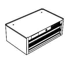
Craftsman CMST25233RB S2000 26 in 5-Drawer Metal Tool Chest
2025-12-11
1 docs
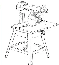
Craftsman 315273731 254 mm 10 in. Stationary Radial Arm Saw
2025-10-27
1 docs
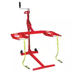
Craftsman CMKGAAV45099000 500 lb. Riding Mower Lift
2025-09-18
1 docs
Craftsman CMXEVCVVBVCM12 Detachable Blower 12-Gallon 6 HP Corded Wet/Dry Vacuum
2025-09-18
1 docs
Craftsman CMXEVXA18115 5-Gallon 4 HP Corded Wet/Dry Shop Vacuum
2025-09-18
1 docs
Craftsman CMCF610B V20* BRUSHLESS RP Cordless Screwdriver Tool Only
2025-09-03
1 docs
Craftsman CMCPS630B V20* BRUSHLESS RP 8-Inch Pole Saw Tool Only
2025-09-03
1 docs
Craftsman CMSTE8VT VERSATRACK Garage Storage System Peg Hooks 8-Piece
2025-09-03
1 docs
Craftsman CMCBL700M1 V20* Cordless Axial Leaf Blower Kit
2025-09-03
1 docs
Craftsman CMCPPR320D1 V20* Cordless 8 ft. Pole Pruner
2025-09-03
1 docs
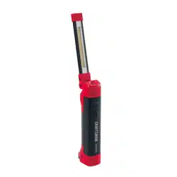
Craftsman CMMT25165 Auto LED Rechargeable Articulating Work Light
2025-09-03
1 docs
Craftsman CMCPS630D1 V20* BRUSHLESS RP 8-Inch Pole Saw
2025-09-03
1 docs
Craftsman CMCF600B V20* BRUSHLESS RP Cordless Drywall Screwgun Tool Only
2025-09-03
1 docs
Craftsman CMEW210 Cordled Electric Detail Sander 1.2 Amp
2025-09-03
1 docs
Craftsman CMCW223B V20* Brushless Cordless RP 3-Inch x 18-Inch Belt Sander Tool Only
2025-09-03
1 docs
Craftsman CMCBL730B V20* BRUSHLESS RP 110 MPH Cordless Handheld Leaf Blower Tool Only
2025-09-03
1 docs
Craftsman 92115201 Portable Air Tank
2025-07-28
1 docs
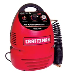
Craftsman 919152390 Home/Hobby Air Compressor
2025-07-28
1 docs
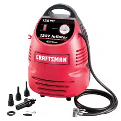
Craftsman 919751110 120V Inflator
2025-07-28
1 docs
Craftsman 919152361 120V Inflator
2025-07-28
1 docs
Popular products
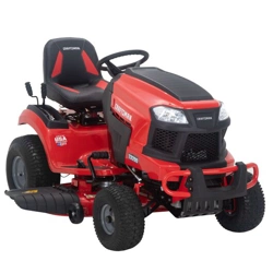
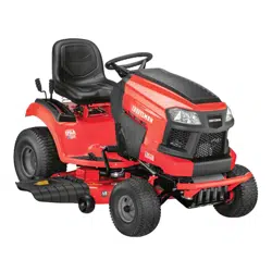
Craftsman CMXGRAM1130036 - T110 42-in 17.5 HP Gear Drive Riding Mower
2021-05-21
3 docs
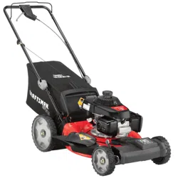
Craftsman CMXGMAM1125499 M110 140-cc 21-in Gas Push Lawn Mower
2021-05-21
2 docs
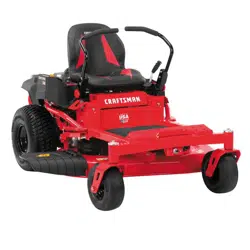
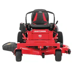
Craftsman CMXGNAM211701 Z5200 42-in. 20 HP* Gas Zero-Turn Riding Mower
2022-08-13
1 docs
Craftsman CMXGMAM201207 M320 21-in 163cc RWD Self-Propelled Mower
2022-08-17
1 docs
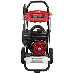
Craftsman CMXGWAS020790 3,000 MAX PSI* Gas Pressure Washer
2022-08-14
2 docs
Craftsman CMXGTAMDSS30 17-in. 30cc 4-Cycle Attachment-Capable Straight Shaft Gas WEEDWACKER® String Trimmer WS4200
2022-08-17
2 docs
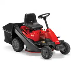
Craftsman CMXGRAM1130035 R110 30-in. 10.5 HP* Gear Drive Gas Mini Riding Mower
2021-05-21
3 docs
Craftsman CMXGRAM211301 T2200 Turn Tight 42-in 19.5-HP Riding Lawn Mower
2022-08-13
1 docs
Craftsman CMXGRAM1130043 T210 Turn Tight 42-in 18 -HP Single Cylinder Gas Riding Lawn Mower
2021-05-21
1 docs
Craftsman CMXGRAM201302 T100 36-in 11.5-HP Gas Riding Lawn Mower
2022-08-17
1 docs
Craftsman 1021499A Garage Door Opener
2022-11-30
1 docs
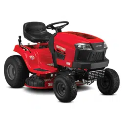
Craftsman CM13APA9ZSA93 T2200K Turn Tight 42-in 20-HP V-twin Gas Riding Lawn Mower
2024-08-12
1 docs
Craftsman CMXGTAMDSS25 WEEDWACKER 25 cc 2-Cycle 17 in Attachment-Capable Straight Shaft Gas Trimmer WS2200
2022-08-16
1 docs
Craftsman CMXGNAM211702 Z5400 46-in. 22.0 HP* Gas Zero-Turn Riding Mower
2022-08-12
1 docs
Craftsman CMXGMAM1125503 M250 160-cc 21-in Self-Propelled Gas Lawn Mower
2021-05-21
2 docs
Craftsman CMMT77693 Automotive OBD2 Code Reader
2022-08-16
1 docs
Craftsman CMXGRAM211303 T3200 54-in. 24.0 HP Gas Riding Lawn Mower
2022-08-18
1 docs
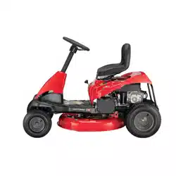
Craftsman 13AC26JD093 R110 Riding Lawn Mower
2023-05-08
1 docs
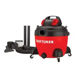
Craftsman CMXEVBCPC1650 5.0 Peak HP Wet/Dry Vac 16 gal
2022-08-18
1 docs
Craftsman CMXGMAM1125500 - M140 160-cc 21-in Gas Push Lawn Mower
2021-05-21
3 docs
Craftsman CMXGNAM211704 Z5800 54-in. 24.0 HP* Gas Zero-Turn Riding Mower
2022-08-12
1 docs
Craftsman CMXGRAM1130044 T240 Turn Tight Riding Mower
2021-05-21
2 docs
Craftsman CMXGNAM1130046 Z510 20-HP V-Twin Dual Hydrostatic 42-in Zero-Turn Lawn Mower
2021-05-21
3 docs
Craftsman CMXGRAM211302 T2400 46-in. 23.0 HP* KOHLER V-Twin Hydrostatic TURNTIGHT™ Gas Riding Lawn Mower
2022-08-15
1 docs
Craftsman CMXGRAM1130037 T110 17.5-HP Manual/Gear 42-in Riding Lawn Mower
2021-05-21
2 docs
Craftsman CMXPTXA1201 Portable 12-volt Tire Inflator Portable Air Compressor
2025-01-08
1 docs
Craftsman CMXGRAM1130047 54-in 24.0 HP* Hydrostatic Riding Mower (T310)
2021-05-21
2 docs
Craftsman CMXRSSC7750 - 7 ft x 7 ft Storage Shed
2022-08-15
1 docs
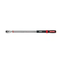
Craftsman CMMT99436 1/2-in Drive Digital Torque Wrench
2022-08-17
1 docs
Craftsman CMXGRAM1130038 - T130 42-in 18.5 HP Automatic Riding Mower
2022-08-14
1 docs
Craftsman CMXGRAM1130045 50-in. 23.0 HP* Hydrostatic TURNTIGHT Gas Riding Mower T260
2021-05-21
2 docs
Craftsman CMXGNAM1130051 Z550 23-HP V-Twin Dual Hydrostatic 50-in Zero-Turn Lawn Mower
2021-05-21
3 docs
Craftsman CMXGMAM201102 - M100 140cc 21 inch Gas Push Mower
2021-05-21
2 docs
Craftsman CMXGIAC3300 3300W Gasoline Powered Portable Inverter Generator
2021-05-21
1 docs
Craftsman CMXGWAS021021 2.3 MAX GPM* Pressure Washer 2800 MAX PSI*
2022-08-13
2 docs
Craftsman CMXGMAM1125501 M210 140-cc 21-in Self-propelled Gas Lawn Mower
2021-05-21
3 docs
Craftsman CMXGAAH46BT Backpack Blower - 2-Cycle Gas Engine - 46 cc - 490 cfm - 220 mph
2021-05-21
2 docs
Craftsman CMCRM233303 56V MAX* 42-in. Battery-Powered Brushless Premium Riding Mower
2023-02-19
1 docs
Craftsman 917203810 19.0 HP*, 42" Mower Electric Start Automatic Transmission Lawn Tractor
2022-12-20
1 docs
Craftsman CMXGWFN061294 Pressure Washer 3100 PSI 2.4 GPM Cold Water
2025-04-16
1 docs