

CRAFTSMAN® is a registered trademark of Stanley Black & Decker, Inc., used under license.
CRAFTSMAN® es una marca registrada de Stanley Black & Decker, Inc., utilizada bajo licencia.
© 2018 CRAFTSMAN U.S. & Canada Only
CRAFTSMAN.com
Form No. 769-16810B
(October 2, 2019)
INSTRUCTION MANUAL | MANUAL DE INSTRUCTIONES
R100 Series
LAWN TRACTOR/TRACTOR CORTACÉSPED
Model Nos. CMXGRAM1130035
CMXGRAM1130040
CMXGRAM1222292
CMXGRAM7368327
IF YOU HAVE QUESTIONS OR COMMENTS, CONTACT US.
SI TIENE DUDAS O COMENTARIOS, CONTÁCTENOS.
1-888-331-4569 WWW.CRAFTSMAN.COM

2
TABLE OF CONTENTS
MODEL NUMBERPRODUCT SPECIFICATIONS
Safe Operation Practices .........................Page 3
Assembly ........................................Page 9
Operation ......................................Page 16
Service and Maintenance ........................Page 21
Off-Season Storage ............................. Page 33
Troubleshooting ............................... Page 34
Español ........................................ Page 36
Warranty Statement ...............Separate Supplement
Engine Series: See Separate Engine Manual
Engine Oil Type: See Separate Engine Manual
Engine Oil Capacity: See Separate Engine Manual
Fuel: Unleaded Gasoline
Model Number ________________________________
Serial Number _________________________________
Date of Purchase _______________________________
Record the model number, serial number,
and date of purchase above.
WARNING
Before using this equipment, read the manual and follow all safety rules and operating instructions. SAVE THESE INSTRUCTIONS!
NOTE: This Operator’s Manual covers several models. Features may vary by model. Not all features in this manual are applicable to all models and the model depicted may differ
from yours.

3
SAFETY INSTRUCTIONS
GENERAL OPERATION
• Read, understand, and follow all instructions on the machine and in the
manual(s) before attempting to assemble and operate. Keep this manual in
a safe place for future and regular reference and for ordering replacement
parts.
• Be familiar with all controls and their proper operation. Know how to stop
the machine and disengage them quickly.
• Never allow children under 14 years old to operate this machine. Children 14
years old and over should read and understand the operation instructions
and safety rules in this manual and should be trained and supervised by a
parent.
• Never allow adults to operate this machine without proper instruction.
• To help avoid blade contact or a thrown object injury, keep bystanders,
helpers, children and pets at least 75 feet from the machine while it is in
operation. Stop machine if anyone enters the area.
• Thoroughly inspect the area where the equipment is to be used. Remove
all stones, sticks, wire, bones, toys, and other foreign objects which could
be picked up and thrown by the blade(s). Thrown objects can cause serious
personal injury.
• Plan your mowing pattern to avoid discharge of material toward roads,
sidewalks, bystanders and the like. Also, avoid discharging material against
a wall or obstruction which may cause discharged material to ricochet back
toward the operator.
• Always wear safety glasses or safety goggles during operation and while
performing an adjustment or repair to protect your eyes. Thrown objects
which ricochet can cause serious injury to the eyes.
• Wear sturdy, rough-soled work shoes and close-fitting slacks and shirts.
Loose fitting clothes and jewelry can be caught in movable parts. Never
operate this machine in bare feet or sandals.
• Be aware of the mower and attachment discharge direction and do not point
it at anyone. Do not operate the mower without the discharge cover or entire
grass catcher in its proper place.
• Do not put hands or feet near rotating parts or under the cutting deck.
Contact with the blade(s) can amputate hands and feet.
• A missing or damaged discharge cover can cause blade contact or thrown
object injuries.
• Stop the blade(s) when crossing gravel drives, walks, or roads and while not
cutting grass.
• Watch for traffic when operating near or crossing roadways. This machine is
not intended for use on any public roadway.
• Do not operate the machine while under the influence of alcohol or drugs.
• Mow only in daylight or good artificial light.
• Never carry passengers.
• Disengage blade(s) before shifting into reverse. Back up slowly. Always look
down and behind before and while backing to avoid a back-over accident.
• Slow down before turning. Operate the machine smoothly. Avoid erratic
operation and excessive speed.
• Disengage blade(s), set parking brake, stop engine and wait until the
blade(s) come to a complete stop before removing grass catcher, emptying
grass, unclogging chute, removing any grass or debris, or making any
adjustments.
• Never leave a running machine unattended. Always turn off blade(s), set
parking brake, stop engine and remove key before dismounting.
• Use extra care when loading or unloading the machine into a trailer or truck.
This machine should not be driven up or down ramp(s), because the machine
could tip over, causing serious personal injury. The machine must be pushed
manually on ramp(s) to load or unload properly.
• Muffler and engine become hot and can cause a burn. Do not touch.
WARNING
This symbol points out important safety instructions which, if not
followed, could endanger the personal safety and/or property of
yourself and others. Read and follow all instructions in this manual
before attempting to operate this machine. Failure to comply with these
instructions may result in personal injury. When you see this symbol, HEED
ITS WARNING!
WARNING
CALIFORNIA PROPOSITION 65
Engine Exhaust, some of its constituents, and certain vehicle components
contain or emit chemicals known to State of California to cause cancer and
birth defects or other reproductive harm.
Battery posts, terminals, and related accessories contain lead and lead
compounds, chemicals known to the State of California to cause cancer and
reproductive harm. Wash hands after handling.
DANGER
This machine was built to be operated according to the safe operation
practices in this manual. As with any type of power equipment,
carelessness or error on the part of the operator can result in serious injury.
This machine is capable of amputating fingers, hands, toes and feet and
throwing debris. Failure to observe the following safety instructions could
result in serious injury or death.
WARNING
Your Responsibility—Restrict the use of this power machine to
persons who read, understand and follow the warnings and instructions in
this manual and on the machine.
SAVE THESE INSTRUCTIONS!

4
SAFETY INSTRUCTIONS
• Check overhead clearances carefully before driving under low hanging tree
branches, wires, door openings etc., where the operator may be struck or
pulled from the machine, which could result in serious injury.
• Disengage all attachment clutches and depress the brake pedal completely
before attempting to start engine.
• Your machine is designed to cut normal residential grass of a height no more
than 12”. Do not attempt to mow through unusually tall, dry grass (e.g.,
pasture) or piles of dry leaves. Dry grass or leaves may contact the engine
exhaust and/or build up on the mower deck presenting a potential fire
hazard.
• Use only accessories and attachments approved for this machine by the
machine manufacturer. Read, understand and follow all instructions
provided with the approved accessory or attachment. For a list of approved
accessories and attachments, call 1-888-331-4569.
• Data indicates that operators, age 60 years and above, are involved in a
large percentage of riding mower-related injuries. These operators should
evaluate their ability to operate the riding mower safely enough to protect
themselves and others from serious injury.
• If situations occur which are not covered in this manual, use care and good
judgment.
SLOPE OPERATION
Slopes are a major factor related to loss of control and tip-over accidents which can result in severe
injury or death. All slopes require extra caution. If you cannot back up the slope or if you feel uneasy on
it, do not mow it.
For your safety, use the Slope Guide included as part of this manual to measure slopes before operating
this machine on a sloped or hilly area. If the slope is greater than 12 degrees as shown on the Slope
Guide, do not operate this machine on that area or serious injury could result.
Do:
• Mow up and down slopes, not across. Exercise extreme caution when
changing direction on slopes.
• Watch for holes, ruts, bumps, rocks, or other hidden objects. Uneven terrain
could overturn the machine. Tall grass can hide obstacles.
• Use slow speed. Choose a low enough speed setting so that you will not have
to stop or shift while on the slope. Tires may lose traction on slopes even
though the brakes are functioning properly. Always keep machine in gear
when going down slopes to take advantage of engine braking action.
• Follow the manufacturer’s recommendations for wheel weights or
counterweights to improve stability.
• Use extra care with grass catchers or other attachments. These can change
the stability of the machine.
• Keep all movement on the slopes slow and gradual. Do not make sudden
changes in speed or direction. Rapid engagement or braking could cause
the front of the machine to lift and rapidly flip over backwards which could
cause serious injury.
• Avoid starting or stopping on a slope. If tires lose traction, disengage the
blade(s) and proceed slowly straight down the slope.
Do Not:
• Do not turn on slopes unless necessary; then, turn slowly and gradually
downhill, if possible.
• Do not mow near drop-offs, ditches or embankments. The mower could
suddenly turn over if a wheel is over the edge of a cliff, ditch, or if an edge
caves in.
• Do not try to stabilize the machine by putting your foot on the ground.
• Do not use a grass catcher on steep slopes.
• Do not mow on wet grass. Reduced traction could cause sliding.
• Do not attempt to coast downhill. Over-speeding may cause the operator to
lose control of the machine resulting in serious injury or death.
• Do not tow heavy pull behind attachments (e.g. loaded dump cart, lawn
roller, etc.) on slopes greater than 5 degrees. When going down hill, the
extra weight tends to push the tractor and may cause you to loose control
(e.g. tractor may speed up, braking and steering ability are reduced,
attachment may jack-knife and cause tractor to overturn).
CHILDREN
Tragic accidents can occur if the operator is not alert to the presence of children. Children are often
attracted to the machine and the mowing activity. They do not understand the dangers. Never assume
that children will remain where you last saw them.
• Keep children out of the mowing area and in watchful care of a responsible
adult other than the operator.
• Be alert and turn machine off if a child enters the area.
• Before and while backing, look behind and down for small children.
• Never carry children, even with the blade(s) shut off. They may fall off and be
seriously injured or interfere with safe machine operation.
• Use extreme care when approaching blind corners, doorways, shrubs, trees
or other objects that may block your vision of a child who may run into the
machine.
• To avoid back-over accidents, always disengage the cutting blade(s) before
shifting into Reverse. If equipped, the “Reverse Caution Mode” (blades
operate while machine rides in reverse) should not be used when children or
others are around.
• Keep children away from hot or running engines. They can suffer burns from
a hot muffler.
• Remove key when machine is unattended to prevent unauthorized
operation.
Never allow children under 14 years of age to operate this machine. Children 14 and over should read
and understand the instructions and safe operation practices in this manual and on the machine and
should be trained and supervised by an adult.
TOWING
• Tow only with a machine that has a hitch designed for towing. Do not attach
towed equipment except at the hitch point.
• Follow the manufacturers recommendation for weight limits for towed
equipment and towing on slopes.
• Never allow children or others in or on towed equipment.
• On slopes, the weight of the towed equipment may cause loss of traction and
loss of control.

5
SAFETY INSTRUCTIONS
• Always use extra caution when towing with a machine capable of making
tight turns (e.g. “zero-turn” ride-on mower). Make wide turns to avoid
jack-knifing.
• Travel slowly and allow extra distance to stop.
• Do not coast downhill.
SERVICE
Safe Handling of Gasoline:
To avoid personal injury or property damage use extreme care in handling
gasoline. Gasoline is extremely flammable and the vapors are explosive.
Serious personal injury can occur when gasoline is spilled on yourself or your
clothes which can ignite. Wash your skin and change clothes immediately.
• Use only an approved gasoline container.
• Never fill containers inside a vehicle or on a truck or trailer bed with a plastic
liner. Always place containers on the ground away from your vehicle before
filling.
• When practical, remove gas-powered equipment from the truck or
trailer and refuel it on the ground. If this is not possible, then refuel such
equipment on a trailer with a portable container, rather than from a gasoline
dispenser nozzle.
• Keep the nozzle in contact with the rim of the fuel tank or container opening
at all times until fueling is complete. Do not use a nozzle lock-open device.
• Extinguish all cigarettes, cigars, pipes and other sources of ignition.
• Never fuel machine indoors.
• Never remove gas cap or add fuel while the engine is hot or running. Allow
engine to cool at least two minutes before refueling.
• Never over fill fuel tank. Fill tank to no more than ½ inch below bottom of
filler neck to allow space for fuel expansion.
• Replace gasoline cap and tighten securely.
• If gasoline is spilled, wipe it off the engine and equipment. Move machine to
another area. Wait 5 minutes before starting the engine.
• To reduce fire hazards, keep machine free of grass, leaves, or other debris
build-up. Clean up oil or fuel spillage and remove any fuel soaked debris.
• Never store the machine or fuel container inside where there is an open
flame, spark or pilot light as on a water heater, space heater, furnace, clothes
dryer or other gas appliances.
• Allow a machine to cool at least five minutes before storing.
General Service
• Never run an engine indoors or in a poorly ventilated area. Engine exhaust
contains carbon monoxide, an odorless, and deadly gas.
• Before cleaning, repairing, or inspecting, make certain the blade(s) and all
moving parts have stopped. Disconnect the spark plug wire and ground against
the engine to prevent unintended starting.
• Periodically check to make sure the blades come to complete stop within
approximately (5) five seconds after operating the blade disengagement
control. If the blades do not stop within the this time frame, your machine
should be serviced professionally by a qualified service dealer.
• Check brake operation frequently as it is subjected to wear during normal
operation. Adjust and service as required.
• Check the blade(s) and engine mounting bolts at frequent intervals for
proper tightness. Also, visually inspect blade(s) for damage (e.g., excessive
wear, bent, cracked). Replace the blade(s) with the original equipment
manufacturer’s (O.E.M.) blade(s) only, listed in this manual. Use of parts
which do not meet the original equipment specifications may lead to
improper performance and compromise safety!
• Mower blades are sharp. Wrap the blade or wear gloves, and use extra
caution when servicing them.
• Keep all nuts, bolts, and screws tight to be sure the equipment is in safe
working condition.
• Never tamper with the safety interlock system or other safety devices. Check
their proper operation regularly.
• After striking a foreign object, stop the engine, disconnect the spark plug
wire(s) and ground against the engine. Thoroughly inspect the machine for
any damage. Repair the damage before starting and operating.
• Never attempt to make adjustments or repairs to the machine while the
engine is running.
• Grass catcher components and the discharge cover are subject to wear
and damage which could expose moving parts or allow objects to be
thrown. For safety protection, frequently check components and replace
immediately with original equipment manufacturer’s (O.E.M.) parts only,
listed in this manual. Use of parts which do not meet the original equipment
specifications may lead to improper performance and compromise safety!
• Do not change the engine governor settings or over-speed the engine. The
governor controls the maximum safe operating speed of the engine.
• Maintain or replace safety and instruction labels, as necessary.
• Observe proper disposal laws and regulations for gas, oil, etc. to protect the
environment.
• According to the Consumer Products Safety Commission (CPSC) and the U.S.
Environmental Protection Agency (EPA), this product has an Average Useful
Life of seven (7) years, or 270 hours of operation. At the end of the Average
Useful Life, buy a new machine or have the machine inspected annually by
a qualified service dealer to ensure that all mechanical and safety systems
are working properly and not worn excessively. Failure to do so can result in
accidents, injuries or death.
DO NOT MODIFY ENGINE
To avoid serious injury or death, do not modify engine in any way. Tampering
with the governor setting can lead to a runaway engine and cause it to
operate at unsafe speeds. Never tamper with factory setting of engine
governor.
6
SAFETY INSTRUCTIONS
SPARK ARRESTOR
WARNING
This machine is equipped with an internal combustion engine and should
not be used on or near any unimproved forest-covered, brush-covered or
grass-covered land unless the engine’s exhaust system is equipped with a
spark arrestor meeting applicable local or state laws (if any).
If a spark arrestor is used, it should be maintained in effective working order
by the operator. In the State of California the above is required by law (Section
4442 of the California Public Resources Code). Other states may have similar
laws. Federal laws apply on federal lands.
A spark arrestor for the muffler is available through your nearest qualified
service dealer.
For location and purchase information, call 1-888-331-4569.
NOTICE REGARDING EMISSIONS
Engines which are certified to comply with California and federal EPA
emission regulations for SORE (Small Off Road Equipment) are certified
to operate on regular unleaded gasoline, and may include the following
emission control systems: Engine Modification (EM), Oxidizing Catalyst (OC),
Secondary Air Injection (SAI) and Three Way Catalyst (TWC) if so equipped.
SAFETY SYMBOLS
This page depicts and describes safety symbols that may appear on this product. Read, understand, and follow all instructions on the machine before
attempting to assemble and operate.
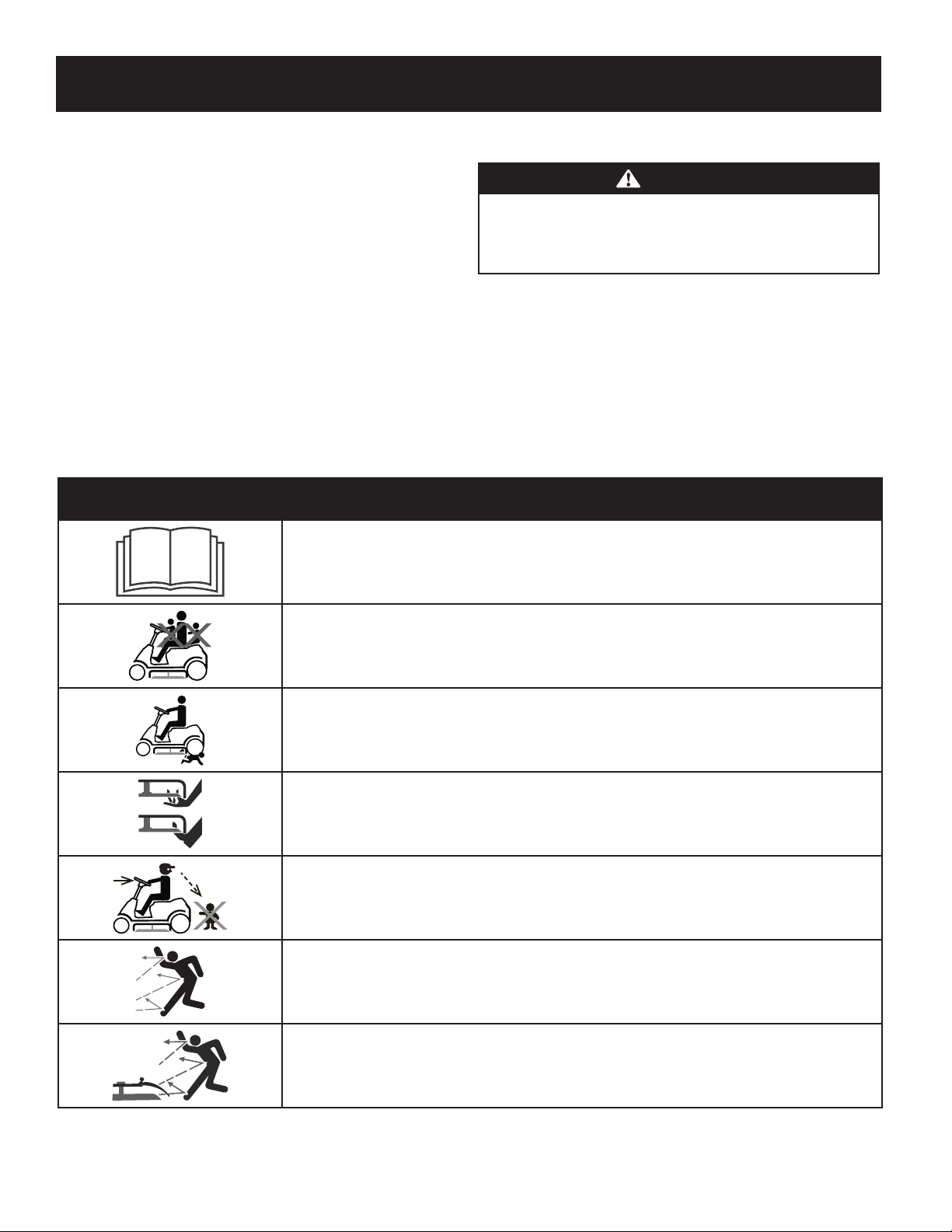
Symbol Description
READ THE OPERATOR’S MANUAL(S)
Read, understand, and follow all instructions in the manual(s) before attempting to assemble and
operate
DANGER— ROTATING BLADES
Never carry passengers. Never carry children, even with the blades off.
DANGER— ROTATING BLADES
To avoid a back-over accident, keep children away from the machine while it is in operation.
WARNING— ROTATING BLADES
Do not put hands or feet near rotating parts or under the cutting deck. Contact with the blade(s) can
amputate hands and feet.
DANGER— ROTATING BLADES
Always look down and behind before and while backing to avoid a back-over accident.
WARNING—THROWN OBJECTS
This machine may pick up and throw and objects which can cause serious personal injury.
WARNING—THROWN OBJECTS
This machine may pick up and throw and objects which can cause serious personal injury.

7
SAFETY INSTRUCTIONS
Symbol Description
BYSTANDERS
Keep bystanders, helpers, children and pets at least 75 feet from the machine while it is in operation.
WARNING— SLOPE OPERATION
Do not operate this machine on a slope greater than 12 degrees.
WARNING— HOT SURFACE
Engine parts, especially the muffler, become extremely hot during operation. Allow engine and
muffler to cool before touching.
DANGER — ROTATING BLADES
To reduce the risk of injury, keep hands and feet away. Do not operate unless discharge cover or grass
catcher is in its proper place. If damaged, replace immediately.
WARNING— CARBON MONOXIDE
Never run an engine indoors or in a poorly ventilated area. Engine exhaust contains carbon
monoxide, an odorless and deadly gas.
DANGER— ROTATING BLADES
Do not step on the cutting deck.
WARNING: Your Responsibility—Restrict the use of this power machine to persons who read, understand and follow
the warnings and instructions in this manual and on the machine.
SAVE THESE INSTRUCTIONS!
8
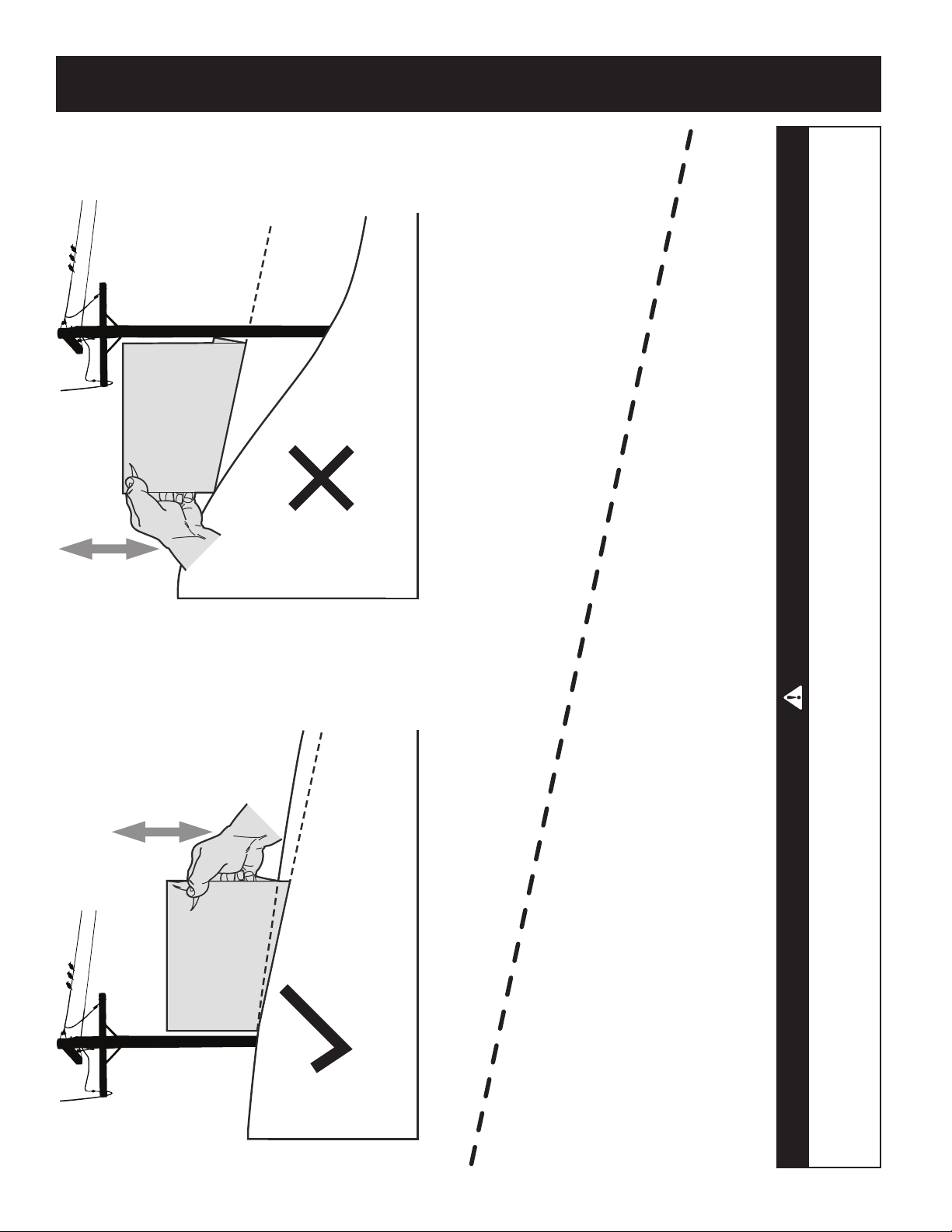
SLOPE GAUGE
(OK) (TOO STEEP)
USE THIS SLOPE GAUGE TO DETERMINE
IF A SLOPE IS TOO STEEP FOR SAFE OPERATION!
To check the slope, proceed as follows:
1. Remove this page and fold along the dashed line.
2. Locate a vertical object on or behind the slope (e.g. a pole, building, fence, tree, etc.)
3. Align either side of the slope gauge with the object (See Figure 1 and Figure 2 ).
4. Adjust gauge up or down until the left corner touches the slope (See Figure 1 and Figure 2).
5. If there is a gap below the gauge, the slope is too steep for safe operation (See Figure 2 above).
12° dashed line
Figure 2Figure 1
12° Slope
12° Slope
WARNING
Slopes are a major factor related to tip-over and roll-over accidents which can result in severe injury or death. Do not operate machine
on slopes in excess of 12 degrees. All slopes require extra caution. If you cannot back up the slope or if you feel uneasy on it, do not
mow it. Always mow up and down the face of slopes, never mow across the face of slopes.
Contents of Hardware Pack
Before beginning installation, remove all the contents from the crate and all the
hardware from the pack to make sure everything is present. Hardware is listed
below. Part numbers are shown in parentheses.
• Hitch Plate
• Seat Mounting Bracket (with two shoulder bolts & lock nuts installed)
Recommended Tools for Assembly
• 3/8” Wrench (or socket) • 9/16” Socket
• 1/2” Wrench (or socket) • 7/16” wrench
• 5/8” Wrench (or socket) • Phillips Screw Driver
• 1/4” Drive Ratchet
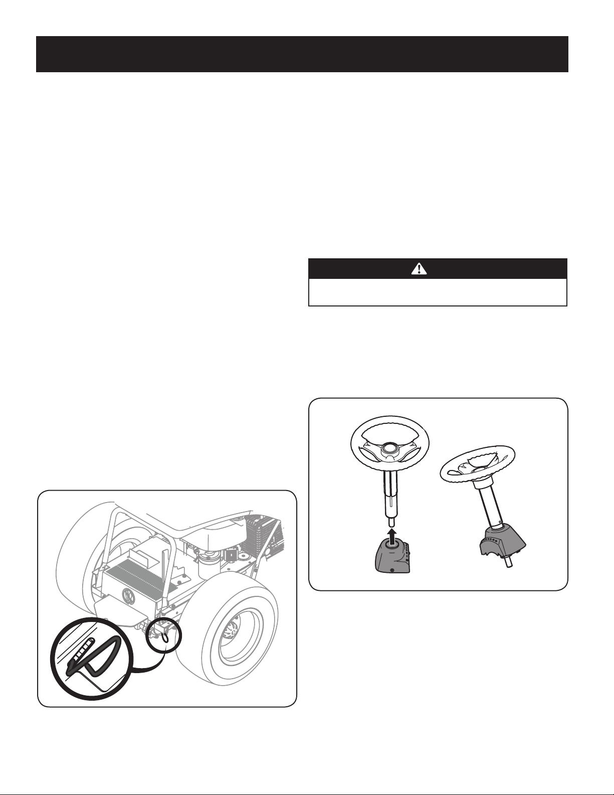
Manually Moving the Tractor
Hydrostatic Tractors
On Hydrostatic tractors, use the transmission bypass rod located inside the right tire on
the lower right section of the frame. When engaged, the rod opens a bypass within the
hydrostatic transmissions, which allows the tractor to be pushed short distances by hand.
1. Engage the transmission bypass rod by pulling out and down to move the
tractor manually without starting it.
2. Disengage the transmission bypass rod by lifting up and allowing it to return
to its disengaged position after manually moving the tractor. See Figure 1.
Figure 1
Note: If the tractor will not move or does not move freely when pushing check if the
bypass lever is fully open or the brake is engaged.
Contents of Crate
• One Riding Mower • One Seat Assembly • One Discharge Chute Assembly
• One Steering Wheel/Shaft Assembly • One Rear Engine Cover • One Hardware Pack
• One Rear Hitch Plate • One Oil Drain Sleeve
• One Riding Mower Operator’s Manual • One Steering Pedestal Cap
Note: The transmission will NOT engage when the hydrostatic bypass rod is pulled
out. Return the rod to its normal position prior to operating the tractor. If the tractor
will not move when pushing on the forward/reverse pedals, or moves slowly, check
to see of the bypass valve is on.
6-Speed Tractors
Engage the brake pedaland put the shift lever into NEUTRAL.
CAUTION
Never tow your tractor. Towing the tractor with the rear wheels on the
ground may cause sever damage to the transmission.
Installing The Steering Wheel Assembly
If the steering wheel assembly for your tractor did not come already installed,
follow the steps below:
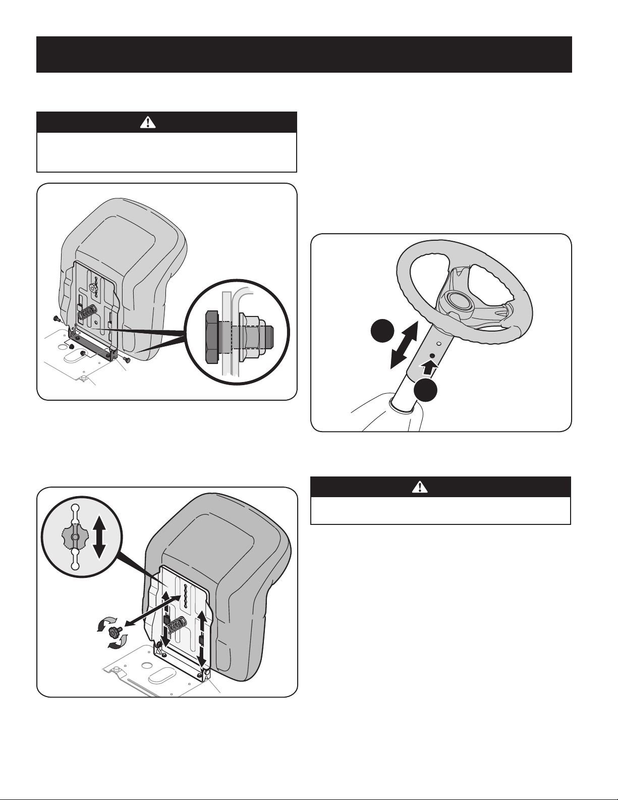
1. Slide the pedestal cap onto the steering shaft so that when the steering
shaft is installed on the tractor, the pedestal cap will be upright as shown in
Figure 2.
Figure 2
2. Remove the shoulder bolt and lock nut from the steering shaft on the tractor
and retain for later steps.
3. With the steering wheel assembly upright and positioned over the lower
steering shaft on the tractor, align the steering wheel so that with the
tractor wheels straight, the large opening on the steering wheel is facing
forward.
9
ASSEMBLY
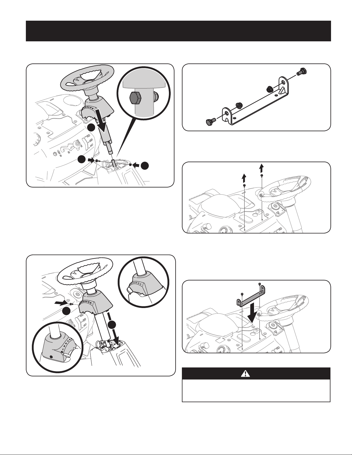
4. Lower the steering wheel assembly onto the lower steering shaft (1) and
secure with bolt and lock nut (2) previously removed. See Figure 2.
1
2
2
Figure 3
5. Tighten the shoulder bolt and lock nut using a 9/16” wrench and
7/16”wrench or socket.
6. Remove the pedestal cap mount screw factory installed and located on the
tractor’s steering console. Retain the screw for later instructions.
7. Slide the Pedestal cap down onto the tractor (1) and slightly rotate to the
right to clip into place. Secure the pedestal with the screw (2) previously
removed. See Figure 4.
1
2
Figure 4
Attaching The Seat
If the seat for your tractor was not attached at the factory, follow the applicable
instructions below to attach it.
1. Remove the shoulder bolts and lock nuts from the seat mounting bracket
included in your hardware pack. See Figure 5.
Figure 5
2. Remove the two self-tapping screws factory installed on the tractor. See
Figure 6.
Figure 6
3. Align the seat bracket in place over the holes from where the self-tapping
screws were removed, as shown in Figure 7.
4. Using a /-inch drive ratchet with a /” socket, secure the seat bracket with
the self-tapping screws removed in Step 2. See Figure 7.
Figure 7
CAUTION
Do not use any type of power tool (e.g. impact gun or electric drill with nut
driver attached) when tightening the self-tapping bolts to attach the seat
bracket.
5. Position the seat assembly over the seat mounting bracket, aligning the
holes provided.
10
ASSEMBLY
6. Install the two shoulder bolts and lock nuts removed from the seat mounting
bracket in Step 1. See Figure 8.
CAUTION
Do not use any type of power tool (e.g. impact gun or electric drill with nut
driver attached) when tightening the self-tapping bolts to attach the seat
bracket.
Figure 8
Seat Adjustment
1. To adjust the position of the seat, remove the adjustment knob on the
bottom of the seat. Slide the seat forward or backward as desired. Reinstall
the adjustment knob. Refer to Figure 9.
Figure 9
Steering wheel height adjustment
To adjust the height of the steering wheel, this unit is equipped with a telescoping
steering column. To adjust the height of the steering wheel:
1. Sit in the operator’s seat and place your hands on the steering wheel.
2. Push the button (a) on the steering column and raise or lower the steering
wheel (b) to the desired position. See Figure 10.
Note: Once the desired position is achieved, lift up and down on the steering wheel
to make sure it locks into place and the button (a) on the steering column releases
into a locked position. Do not operate this unit unless the steering column is in a
locked position.
a
b
Figure 10
Installing The Deck Chute
WARNING
NEVER operate this tractor without either the mulch plug or deck chute
installed.
1. Remove the wing knobs installed on the mowing deck and retain for later
installation.
2. Install the deck chute into the deck discharge opening on the deck. The rear
of the chute should be under the tab on the rear deck bracket. See inset in
Figure 11. The studs on the deck surface will fit through the holes on the
upper portion of the deck chute. The small tab on the deck lip area will fit
through the square cutout on the lower portion of the deck chute. See inset
of Figure 11.
Note: Make certain that the upper-rear portion of deck chute is depressing
the safety switch located on the deck surface and under the tab on the rear
deck bracket. The engine will not start without the deck chute properly in
place.
11
ASSEMBLY
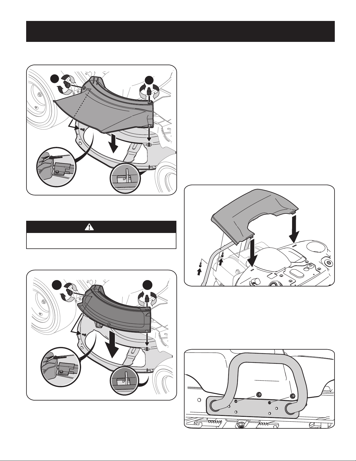
3. Secure the deck chute by tightening the wing knobs removed earlier. See
Figure 11.
1
2
Figure 11
Installing the Mulch Plug
WARNING
NEVER operate this tractor without either the mulch plug or deck chute
installed.
1. Remove the wing knobs installed on the mowing deck and retain for later
installation. See Figure 12.
1
2
Figure 12
2. Install the mulch plug into the deck discharge opening on the deck. The rear
of the mulch plug should be under the tab on the rear deck bracket. The
studs on the deck surface will fit through the holes on the upper portion of
the mulch plug. The small tab on the deck lip area will fit through the square
cutout on the lower portion of the mulch plug. See Figure 12.
Note: Make certain that the upper-rear portion of mulch plug is depressing
the safety switch located on the deck surface and under the tab on the rear
deck bracket. The engine will not start without the mulch plug properly in
place.
3. Secure the mulch plug by tightening the wing knobs removed in step 1.
Install The Rear Engine Cover
1. Remove the two factory installed hex screws located on the rear engine
cover mounting bracket. Retain the screws for later instructions. See
Figure 13.
2. Install the rear engine cover by positioning it in place as shown in Figure 13.
Tip the engine cover forward to fit it into the slots provided, then rotate it
backwards to align the mounting holes.
Figure 13
3. Secure the cover with the two hex screws previously removed. Do not to
over-tighten.
Installing the Bumper
1. Remove the two screws as shown in Figure 14.
2. Position the bumper over the mounting holes and secure using the hardware
removed in Step 1, as shown in Figure 14.
Figure 14
12
ASSEMBLY
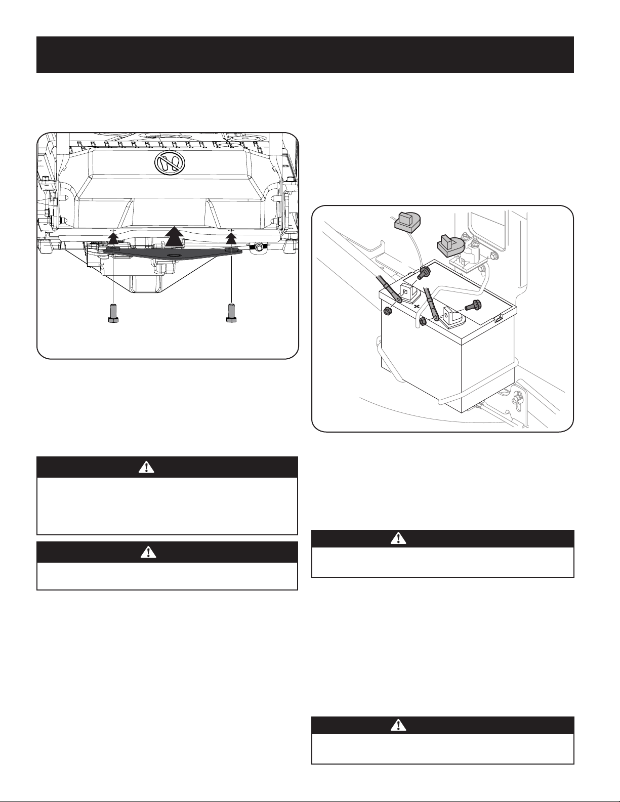
Installing the Hitch Plate
1. Slide the hitch plate in between the frame and the rear cover on your rider.
See Figure 15.
Figure 15
2. When the holes in the hitch plate and the frame are aligned, install the two
hex screws from the manual bag up through the frame and into the hitch
plate. See Figure 15.
3. Securely tighten the hitch plate.
Connecting the Battery Cables
WARNING
CALIFORNIA PROPOSITION 65
Battery posts, terminals, and related accessories contain lead and lead
compounds, chemicals known to the State of California to cause cancer and
reproductive harm. Wash hands after handling.
CAUTION
When attaching battery cables, always connect the POSITIVE (Red) wire to
its terminal first, followed by the NEGATIVE (Black) wire.
For shipping reasons, both battery cables on your equipment may have been left
disconnected from the terminals at the factory. To connect the battery cables,
proceed as follows:
NOTE: The positive battery terminal is marked Pos. (+). The negative battery
terminal is marked Neg. (–).
1. Remove the factory installed hex bolts and hex nuts located on the end of
the wiring harness. Retain the hardware for later instructions.
2. Remove the plastic cover, if present, from the positive battery terminal and
attach the red cable to the positive battery terminal (+) with one of the hex
bolt and hex nuts, using a 7/16 inch wrench and socket wrench. See Figure 16.
3. Remove the plastic cover, if present, from the negative battery terminal
and attach the black cable to the negative battery terminal (–) with the
remaining hex bolt and hex nut, using a 7/16 inch wrench and socket
wrench. See Figure 16.
4. Position the red rubber boot over the positive battery terminal to help
protect it from corrosion.
NOTE: If the battery is put into service after the date shown on top/side of battery,
charge the battery as instructed in the Maintenance section of this Operator’s
Manual prior to operating the tractor.
Figure 16
Gas & Oil
NOTE: The engine is shipped without gasoline and with motor oil in the engine.
However, you MUST check the oil level before operating. Be careful not to overfill.
Running the engine with insufficient oil can cause serious engine damage and void
the engine warranty.
WARNING
Always keep hands and feet clear of equipment moving parts. Do not use a
pressurized starting fluid. Vapors are flammable.
Oil Recommendations
Before starting engine, check oil level, capacity is 1700 ml/57.5 fl. oz. Refer to
viscosity chart in Figure 3-1 for oil recommendations. Do not over-fill. Use a
4-stroke, or an equivalent high detergent, premium quality motor oil certified
to meet or exceed U.S. automobile manufacturer’s requirements for service
classification of a minimum level SJ (higher letter ratings are acceptable such as SL
and SM grades). Motor oil will display this designation on the container.
SAE 10W-30 is recommended for general, all temperature use. If single viscosity oil
is used, select the appropriate viscosity for the average temperature in your area
from the chart below.
CAUTION
Do not use non-detergent oil or 2-stroke engine oil. It could shorten the
engine’s service life.
13
ASSEMBLY
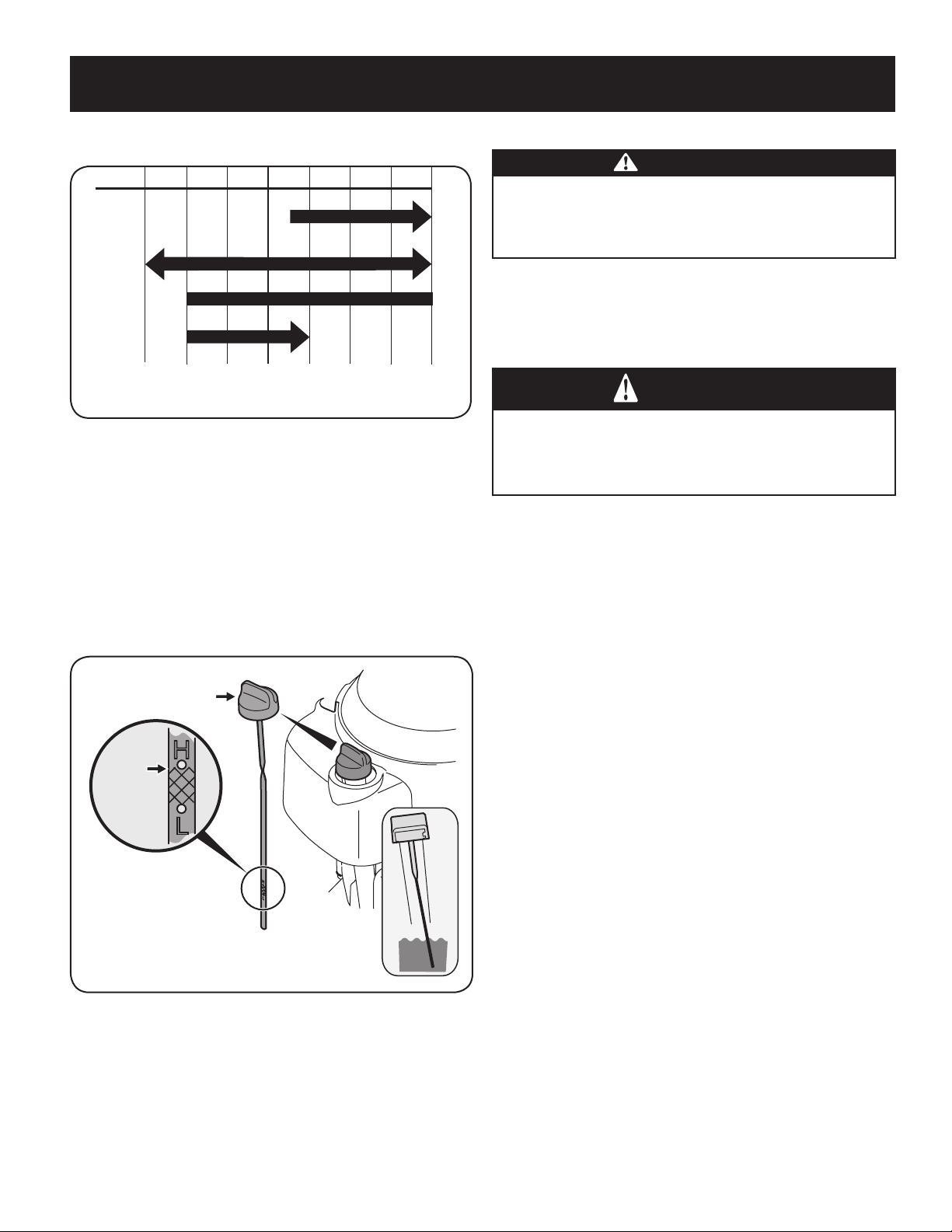
NOTE: A 5w30 synthetic oil may be used to improve start ability for cold weather
(temperatures below 40 F).
-30º -20º -10º 0º
0º 15º 30º 50º 70º 85º 105º
10º 20º 30º 40º
-20º
(ºC)
(ºF)
5W-30
30
10W-30
Synthetic 5W-30
Checking The Oil Level
NOTE: Be sure to check the oil while on a level surface with the engine stopped.
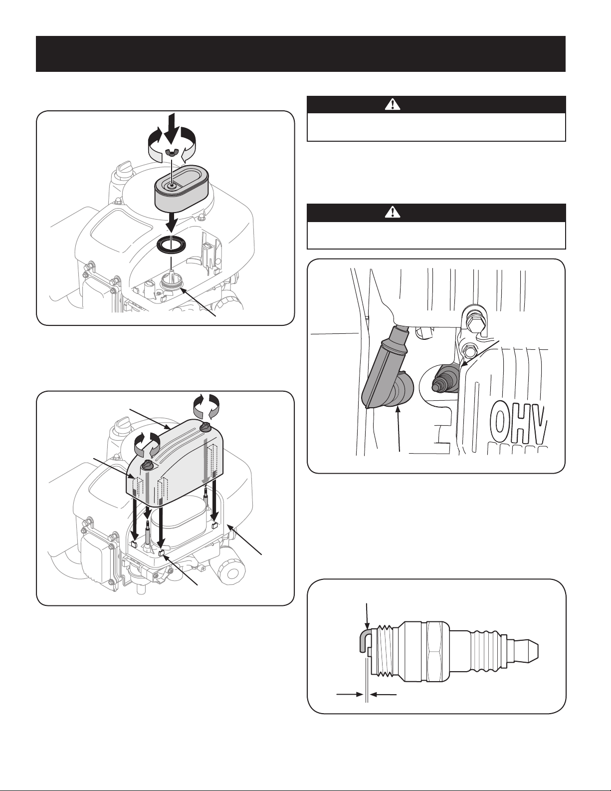
1. Remove the oil filler cap/dipstick and wipe the dipstick clean.
2. Insert the dipstick into the oil filler neck. Turn the dipstick 1/4 turn into the
locked position to fully seat. See Figure 17.
3. Remove dipstick to check the oil level.
4. If the level is low, slowly add oil until the reading is at the upper level on the
dipstick. See Figure 17 inset.
5. Reinsert the dipstick and turn to locked position before starting the engine.
Upper
Level
Oil Fill
Cap/Dipstick
Figure 17
NOTE: Do not overfill. Overfilling with oil may cause smoking, hard starting,
spark plug fouling, or oil saturation of air cleaner.
Fuel Requirements
CAUTION
Operating the engine with E85 fuel, an oil/gasoline mixture, dirty gasoline,
or gasoline over 30 days old without fuel stabilizing additive may result
in damage to your engine’s carburetor. Subsequent damage would not be
covered under the Craftsman warranty.
Use automotive gasoline (unleaded or low leaded to minimize combustion chamber
deposits) with a minimum of 87 octane. Gasoline with up to 10% ethanol or 15%
MTBE (Methyl Tertiary Butyl Ether) can be used. Never use an oil/gasoline mixture
or dirty gasoline. Avoid getting dirt, dust, or water in the fuel tank. DO NOT use E85
gasoline.
WARNING
Use extreme care when handling gasoline. Gasoline is extremely flammable
and the vapors are explosive. Never fuel machine indoors or while the
engine is hot or running. Extinguish cigarettes, cigars, pipes, and other
sources of ignition.
NOTE : Purchase gasoline in small quantities. Do not use gasoline left over from the
previous season, to minimize gum deposits in the fuel system.
• This engine is certified to operate on unleaded gasoline. For best results, fill
the fuel tank with only clean, fresh, unleaded gasoline with a pump sticker
octane rating of 87 or higher.
• Gasohol (up to 10% ethyl alcohol, 90% unleaded gasoline by volume) is an
approved fuel. Other gasoline/alcohol blends, such as E85, are not approved.
• Methyl Tertiary Butyl Ether (MTBE) and unleaded gasoline blends (up to a
maximum of 15% MTBE by volume) are approved fuels. Other gasoline/ether
blends are not approved.
• Fill fuel tank outdoors or in well-ventilated area.
• Do not overfill fuel tank. Fill tank to no more than 1/2 inch below bottom of
filler neck to allow space for fuel expansion.
• Never remove gas cap or add fuel while the engine is hot or running. Allow
engine to cool at least two minutes before refueling.
• If gasoline is spilled, wipe it off the engine and equipment. Move machine to
another area. Wait 5 minutes before starting the engine.
To Add Gasoline
NOTE: The tractor is fitted with a tethered, ratcheting fuel cap. STOP filling the tank
once the fuel is seen inside the filler neck. This ensures that a proper expansion
volume is created, otherwise the fuel can overflow creating a hazardous situation.
Do NOT top off the fuel tank.
• Refuel in a well-ventilated area with the engine stopped. Do not smoke or
allow flames or sparks in the area where the engine is refueled or where
gasoline is stored.
• Do not overfill the fuel tank. After refueling, make sure the tank cap is closed
properly and securely.
• Be careful not to spill fuel when refueling. Spilled fuel or fuel vapor may
ignite. If any fuel is spilled, make sure the area is dry before starting the
engine.
14
ASSEMBLY
• Avoid repeated or prolonged contact with skin or breathing of vapor.
Adding Fuel
WARNING
An adult should fuel this engine. NEVER allow children to refuel its engine.
Gasoline (fuel) vapors are highly flammable and can explode. Fuel vapors
can spread and be ignited by a spark or flame many feet away from engine.
To prevent injury or death from fuel fires, follow these instructions:
• DO NOT use leaded fuel.
• Fuel must be fresh and clean. NEVER use fuel left over from last season or
stored for long periods.
• NEVER mix oil with fuel.
• DO NOT use fuel containing Methanol (Wood Alcohol)
NOTE: Before refueling, allow engine to cool two minutes.
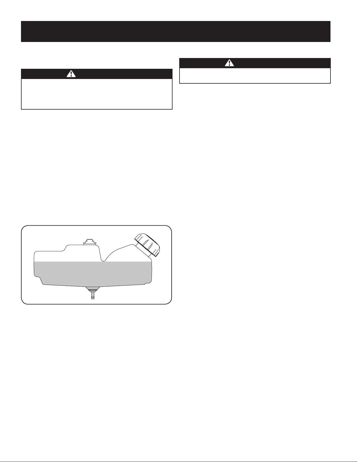
1. Turn the engine off and let engine cool at least 2 minutes before removing
the fuel cap. The gasoline tank is located under the seat. The fuel cap is
tethered to the tractor to prevent its loss. Do not attempt to remove the cap
from the tractor.
2. Clean around fuel fill before removing cap to fuel.
3. Fill tank until fuel reaches ⁄ inch below the bottom of the filler neck to
allow space for fuel expansion. Be careful not to overfill. See Figure 18.
Figure 18
4. Replace the gasoline cap and tighten securely. Wipe up spilled fuel before
starting engine. If fuel is spilled DO NOT start engine. Move machine away
from area of spillage. Avoid creating any source of ignition until fuel vapors
are gone.
Tire Pressure
WARNING
Equal tire pressure should be maintained at all times. Never exceed the
maximum inflation pressure shown on the sidewall of the tire.
The recommended operating tire pressure is:
• Approximately 10 psi for the rear tires
• Approximately 14 psi for the front tires
IMPORTANT: Refer to the tire sidewall for exact tire manufacturer’s recommended
or maximum psi. Do not overinflate. Uneven tire pressure could cause the cutting
deck to mow unevenly.
15
ASSEMBLY
16
OPERATION
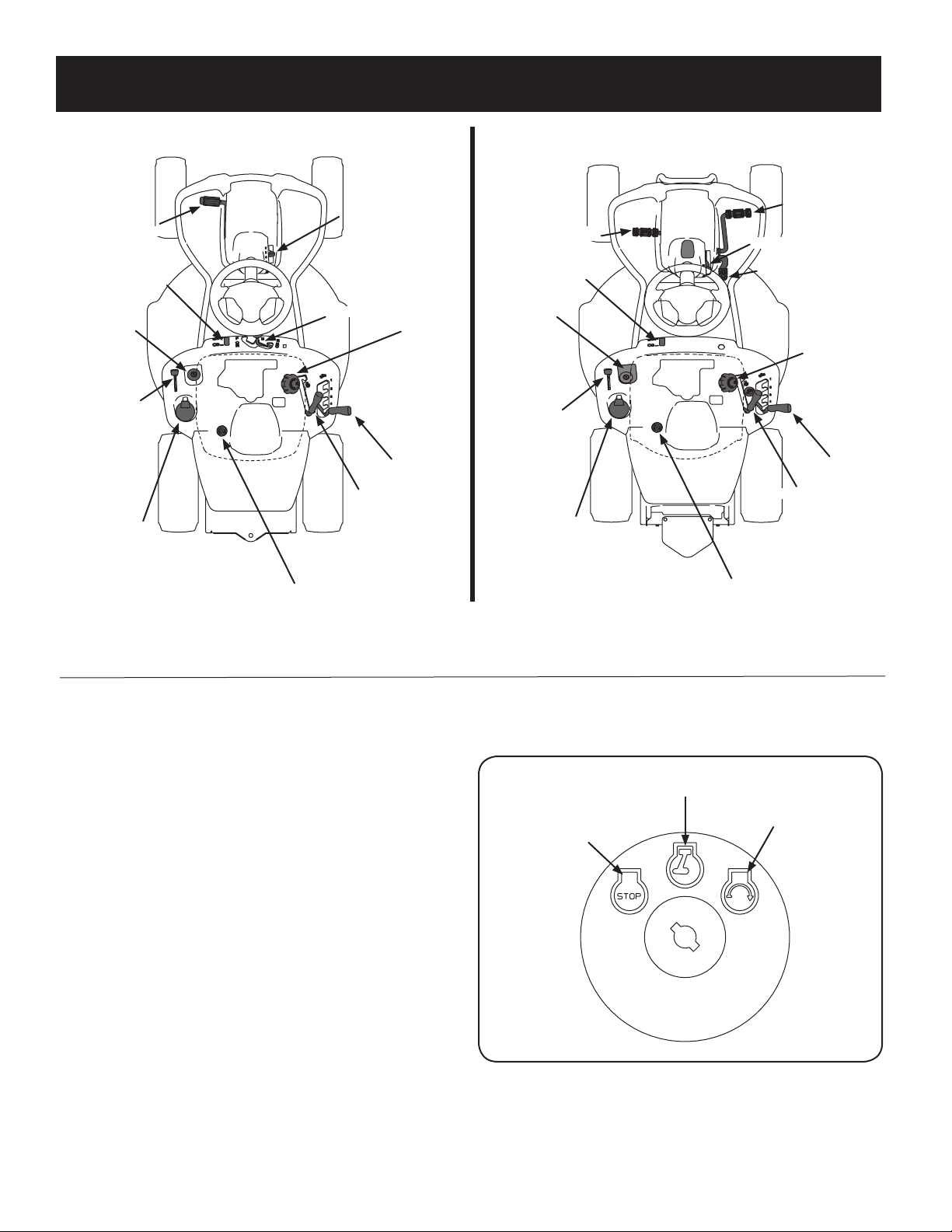
Speed Control &
Parking Brake Lever
Cup Holder
Throttle/Choke Lever
Ignition Switch
Oil Fill Cap
Fuel Fill Cap
Fuel Level Indicator
Clutch/Brake Pedal
Shift Lever
Deck Lift Lever
PTO (Blade Engage) Lever
Reverse Drive Pedal
Brake Pedal
Parking Brake Lever
Forward Drive Pedal
Fuel Fill Cap
Deck Lift Lever
PTO (Blade Engage) Lever
Ignition Switch
Fuel Level Indicator
Throttle/Choke Lever
Cup Holder
Oil Fill Cap
6-Speed
Hydro
Figure 19
NOTE: Any reference in this manual to the RIGHT or LEFT side of the tractor is observed from operator’s seat position facing forward towards the front of tractor.
Meets ANSI Safety Standards
Craftsman Tractors conform to the safety standard of the American National Standards Institute (ANSI).
Throttle / Choke Control
The throttle control lever is located on the left fender of the tractor as seen from the
operator’s position, see Figure 19. This lever controls the speed of the engine, as well
as the choke when it is pushed all the way forward. When set in a given position,
the throttle will maintain a uniform engine speed.
IMPORTANT: When operating the tractor with the cutting deck engaged, be certain
that the throttle lever is always in the FAST (rabbit) position.
Moving the throttle lever all the way forward activates the engine’s choke control.
Activating the choke control closes the choke plate on the carburetor and aids in
starting the engine.
Refer to Starting The Engine in the Operation section of this manual for detailed
starting instructions.
Ignition Switch
The ignition switch is located on the left fender of the tractor as seen from the
operator’s position, adjacent to the Throttle/Choke Control. Activate the Ignition
Switch to start the engine by inserting the key into the ignition switch and turn
clockwise to the START position. Release the key into the ON position once engine
has fired. See Figure 20.
Off
On
Start
Figure 20
17
OPERATION
Reverse Drive Pedal (Hydro Tractors Only)
The reverse drive pedal is located on the right side of the riding mower along the
running board. Ground speed is also controlled with the reverse drive pedal. The
further downward the pedal is pivoted, the faster the riding mower will travel. The
pedal will return to its original/neutral position when it’s not pressed.
Brake Pedal (Hydro Tractors) &
Clutch-Brake Pedal (6-Speed Tractors)
The brake pedal or clutch-brake pedal is located on the left side of the tractor, along
the running board. Depress the pedal all the way down to engage the brake and
bring the riding mower to a complete stop.
Note: The brake pedal must be completely depressed to start the engine. Refer to
Safety Interlock Switches for more information.
Parking Brake
To set the parking brake, fully depress the brake (Hydro tractors) or clutch-brake
pedal (6-Speed tractors). On 6-Speed tractors, move the speed control lever all the
way down and into the parking brake position. On Hydro tractors, move the parking
brake lever all the way down into the parking brake engage position. Release the
brake pedal or clutch-brake pedal to allow the parking brake to engage.
To release the parking brake, depress the brake pedal and move the parking brake
lever or speed control lever out of the parking brake position into the desired
position. Release the clutch-brake pedal.
NOTE: The parking brake must be set if the operator leaves the seat with the engine
running or the engine will automatically shut off.
Fuel Level Indicator
The Fuel Lever Indicator is located below the seat on the left hand side from the
operator’s position in the control panel. Use this window to identify the tractor’s
fuel needs. See Figure 22.
Figure 22
Clutch-Brake Pedal
The clutch-brake pedal is located on the left side of the lawn tractor, along the
running board. Depress the clutch-brake pedal part way down when slowing the
tractor by changing speeds (Refer to Speed Control Lever). Depress the pedal all the
way down to engage the disc brake and bring the tractor to a complete stop.
NOTE: The clutch-brake pedal must be completely depressed to start the engine.
Refer to Safety Interlock Switches in the Operation section of this manual.
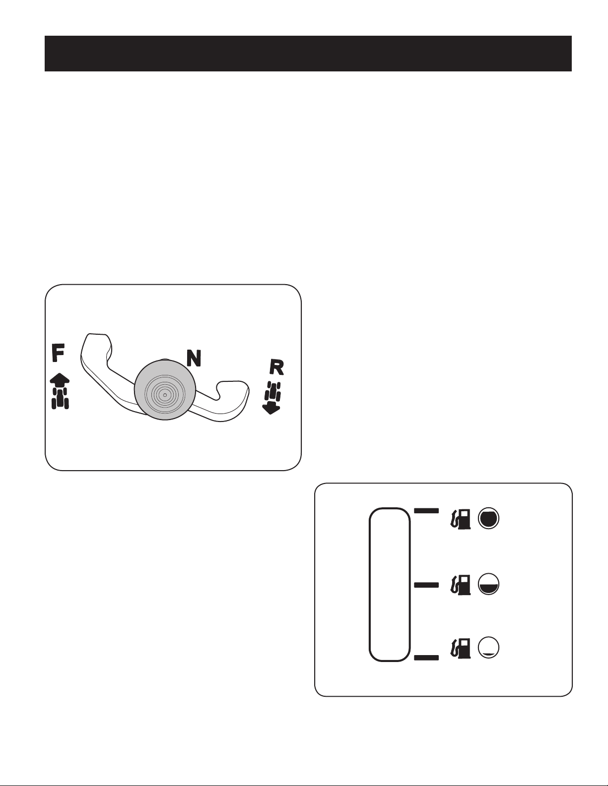
Shift Lever (6-Speed Tractors Only)
The shift lever is located on the control panel just below the seat, in the center of
the tractor. It has three positions, FORWARD, NEUTRAL and REVERSE. The brake
pedal must be completely depressed and the tractor must not be in motion
when moving the shift lever. See Figure 21.
IMPORTANT: Never force the shift lever. Doing so may result in serious damage to
the tractor’s transmission.
Figure 21
Speed Control Lever (6-Speed Tractors Only)
The speed control lever, located on the right side of the tractor’s steering console,
allows you to regulate the ground speed of the lawn tractor.
To use, depress the clutch-brake pedal and move the lever out of the parking brake
notch and forward to increase the tractor’s ground speed. When a desired speed has
been reached, release the lever into an appropriate notch to maintain that speed.
To slow the tractor’s ground speed, depress the clutch-brake pedal and move the
speed control lever rearward and release it into a notch.
Forward Drive Pedal (Hydro Tractors Only)
The forward drive pedal is located on the right side of the machine, along the
running board. Press the forward drive pedal forward to cause the riding mower to
travel forward. Ground speed is also controlled with the forward drive pedal. The
further forward the pedal is pivoted, the faster the riding mower will travel. The
pedal will return to its original/neutral position when it’s not pressed.
18
OPERATION
Deck Lift Lever
Found on your tractor’s right fender, the deck lift lever is used to change the height
of the cutting deck. To use, move the lever to the left, then place in the notch best
suited for your application.
PTO (Blade Engage) Lever
Found on the tractor’s right fender, the PTO (blade engage) lever is used to engage
power to the cutting deck. To operate, move the lever all the way forward. Moving
the lever all the way rearward into the PTO OFF position disengages power to the
cutting deck.
NOTE: The PTO (blade engage) lever must be in the disengaged (PTO OFF) position
when starting the engine.
Fuel Fill Cap
The Fuel Fill Cap is located below the seat. Refer to the Assembly section in this
manual for instructions on fueling this tractor.
Oil Fill Cap
The Oil Fill Cap is located below the seat. Refer to the Assembly section in this
manual for instructions on checking and adding oil to this tractor.
Fuel Fill Cap
The gasoline tank is located under the seat. Do not overfill.
WARNING
Use extreme care when handling gasoline. Gasoline is extremely flammable
and the vapors are explosive. Never fuel machine indoors or while the
engine is hot or running. Extinguish cigarettes, cigars, pipes, and other
sources of ignition.
For detailed information on adding fuel, refer to Fuel Requirements in the Assembly
section of this manual.
Safety Interlock Switches
The safety interlock system is designed for safe operation of the tractor. If this
system should ever malfunction, do not operate the tractor.
Immediately contact 1-888-331-4569 to have the system serviced.
• The safety interlock system prevents the engine from starting unless
the parking brake is engaged and the PTO (Blade Engage) lever is in the
disengaged (OFF) position.
• The safety interlock system will automatically shut off the engine if the
operator leaves the seat before engaging the parking brake.
• The safety interlock system will automatically shut off the engine if the
operator leaves the tractor’s seat with the PTO (Blade Engage) lever engaged,
regardless of whether the parking brake is engaged.
• The engine will automatically shut off if the PTO (Blade Engage)lever is
moved into the engaged (ON) position with the shift lever in Reverse.
WARNING
Do not operate the tractor if the interlock system is malfunctioning. This
system was designed for your safety and protection.
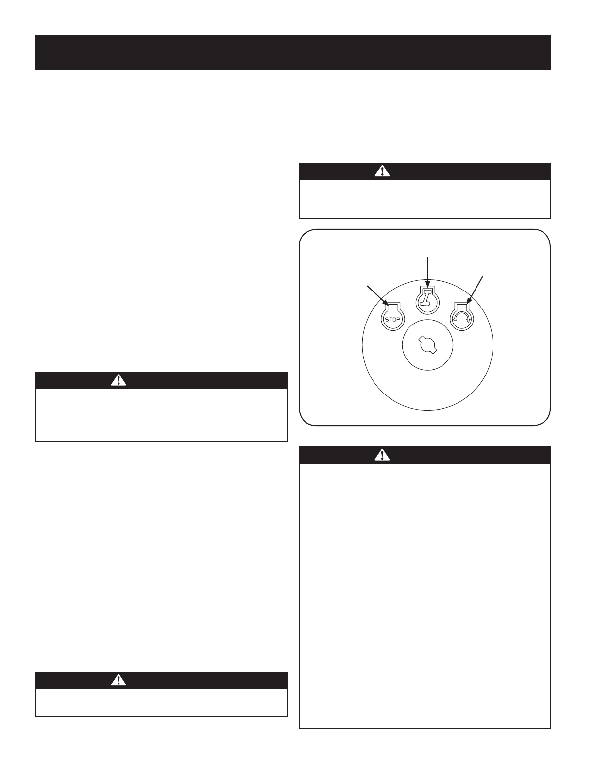
Ignition Switch
The ignition switch is activated to start the engine. Insert key into the ignition
switch and turn clockwise to the START position. Release the key into the ON
position once engine has fired. See Figure 23.
To stop the engine, turn the ignition key counterclockwise to the OFF position. See
Figure 23.
WARNING
Never leave a running machine unattended. Always disengage PTO, move
shift lever into neutral position, set parking brake, stop engine and remove
key to prevent unintended starting.
Off
On
Start
Figure 23
WARNING
Avoid Serious Injury or Death
• Know location and function of all controls.
• Remove objects which could be thrown by the blades.
• Go up and down slopes, not across.
• Use extra caution on slopes. Do not mow slopes greater than 12 degrees.
Avoid sudden turns. Use low speed.
• Do not operate machine where it could tip or slip.
• If machine stops going uphill, stop blades and back down slowly.
• Before leaving operator’s position, disengage blades, engage parking
brake, shut off and remove key.
• Be sure blades and engine are stopped before placing hands or feet near
blades.
• Keep safety devices (guards, shields, switches, etc.) in place and working.
• Keep bystanders away.
• Allow machine to cool before fueling or storing.
• Keep machine free of debris.
Read Operator’s Manual

19
OPERATION
Engaging the Parking Brake
To engage the parking brake:
1. Fully depress the brake pedal and hold it down with your foot.
2. Move the parking brake lever down into the parking brake position.
3. Release the brake pedal to allow the parking brake to engage.
To release the parking brake:
1. Depress the brake pedal and move the speed control lever out of the parking
brake position.
Setting the Cutting Height
Select the height position of the cutting deck by placing the deck lift lever in any of
the different cutting height notches on the right side of the fender.
WARNING
Keep hands and feet away from the discharge opening of the cutting deck.
Starting the Engine
WARNING
Do not operate the tractor if the interlock system is malfunctioning. This
system was designed for your safety and protection.
NOTE: Refer to the Assembly section of this manual for gasoline and oil fill-up
instructions.
1. Insert the tractor key into the ignition switch.
2. Place the PTO (Blade Engage) lever in the disengaged (OFF) position.
3. Engage the tractor’s parking brake.
4. Activate the choke control.
5. Turn the ignition key clockwise to the START position. After the engine starts,
release the key. It will return to the ON position.
WARNING
IMPORTANT: Do NOT hold the key in the START position for longer than ten
seconds at a time. Doing so may cause damage to your engine’s electric
starter.
6. After the engine starts, deactivate the choke control by placing the throttle
control into the FAST position.
NOTE: Do NOT leave the choke control on while operating the tractor. Doing so will
result in a “rich” fuel mixture and cause the engine to run poorly.
Stopping the Engine
WARNING
If you strike a foreign object, stop the engine, disconnect the spark plug
wire(s) and ground against the engine. Thoroughly inspect the machine for
any damage. Repair the damage before restarting and operating.
1. If the blades are engaged, place the PTO (Blade Engage) lever in the
disengaged (OFF) position.
2. Turn the ignition key counterclockwise to the STOP position.
3. Remove the key from the ignition switch to prevent unintended starting.
Driving The Tractor
WARNING
Avoid sudden starts, excessive speed and sudden stops.
WARNING
Do not leave the seat of the tractor without first placing the PTO (Blade
Engage) lever in the disengaged (OFF) position, depressing the brake pedal
and engaging the parking brake. If leaving the tractor unattended, also
turn the ignition key off and remove the key.
WARNING
Always look down and behind before and while backing up to avoid a back-
over accident.
1. Depress the brake pedal and move the speed control lever out of the parking
brake position,then let the pedal release.
2. Move the throttle lever into the FAST (rabbit) position.
3. Place the shift lever in either the FORWARD or REVERSE position.
IMPORTANT: Do NOT use the shift lever to change the direction of travel when the
tractor is in motion. Always use the brake pedal to bring the tractor to a complete
stop before shifting.
4. Release the parking brake by depressing the clutch-brake pedal and
positioning the speed control lever in desired position.
IMPORTANT: First-time operators should use speed positions 1 or 2. Become
completely familiar with the tractor’s operation and controls before operating the
tractor in higher speed positions.
5. Release clutch-brake pedal slowly to put unit into motion.
6. The lawn tractor is brought to a stop by depressing the clutch-brake pedal.
NOTE: When operating the unit initially, there will be little difference between the
highest two speeds until after the belts have seated themselves into the pulleys
during the break-in period.
WARNING
Before leaving the operator’s position for any reason, disengage the blades, place
the shift lever in neutral, engage the parking brake, shut engine off and remove
the key.
IMPORTANT: When stopping the tractor for any reason while on a grass surface,
always:
1. Place the shift lever in neutral,
2. Engage the parking brake,
3. Shut engine off and remove the key. Doing so will minimize the possibility
of having your lawn ‘‘browned’’ by hot exhaust from your tractor’s running
engine.
If unit stalls with speed control in high speed, or if unit will not operate with speed
control lever in a low speed position, proceed as follows:
1. Place shift lever in NEUTRAL.
2. Restart engine.

20
OPERATION
Mowing
WARNING
To help avoid blade contact or a thrown object injury, keep bystanders,
helpers, children and pets at least 75 feet from the machine while it is in
operation. Stop machine if anyone enters the area.
The following information will be helpful when using the cutting deck with your
tractor:
WARNING
Plan your mowing pattern to avoid discharge of materials toward roads,
sidewalks, bystanders and the like. Also, avoid discharging material against
a wall or obstruction which may cause discharged material to ricochet back
toward the operator.
• Do not mow at high ground speed, especially if a mulch kit or grass collector
is installed.
• For best results it is recommended that the first two laps be cut with the
discharge thrown towards the center. After the first two laps, reverse the
direction to throw the discharge to the outside for the balance of cutting.
This will give a better appearance to the lawn.
• Do not cut the grass too short. Short grass invites weed growth and yellows
quickly in dry weather.
• Mowing should always be done with the engine at full throttle.
• Under heavier conditions it may be necessary to go back over the cut area a
second time to get a clean cut.
• Do NOT attempt to mow heavy brush and weeds and extremely tall grass.
Your tractor is designed to mow lawns, NOT clear brush.
• Keep the blade sharp and replace the blade when worn. Refer to Cutting
Blade in the Maintenance section of this manual for proper blade sharpening
instructions.
• The lamps turn OFF when the ignition key is moved to the STOP position.
3. Place speed control lever in highest speed position.
4. Release clutch-brake pedal fully.
5. Depress clutch-brake pedal.
6. Place speed control lever in desired position.
7. Place shift lever in either FORWARD or REVERSE, and follow normal operating
procedures.
Driving On Slopes
Refer to the SLOPE GAUGE in the Safety Instructions section of the manual to help
determine slopes where you may operate this tractor safely.
WARNING
Do not mow on inclines with a slope in excess of 12 degrees (a rise of
approximately 2 feet every 10 feet). The tractor could overturn and cause
serious injury.
• Mow up and down slopes, NEVER across.
• Exercise extreme caution when changing direction on slopes.
• Watch for holes, ruts, bumps, rocks, or other hidden objects. Uneven terrain
could overturn the machine. Tall grass can hide obstacles.
• Avoid turns when driving on a slope. If a turn must be made, turn down the
slope. Turning up a slope greatly increases the chance of a roll over.
• Avoid stopping when driving up a slope. If it is necessary to stop while
driving up a slope, start up smoothly and carefully to reduce the possibility
of flipping the tractor over backward.
Engaging the Blades
Engaging the PTO (Blade Engage) transfers power to the cutting deck. To engage
the blades, proceed as follows:
1. Move the throttle/choke control lever to the FAST (rabbit) position.
2. Grasp the PTO (Blade Engage) lever and pivot it all the way forward into the
engaged (ON) position.
3. Keep the throttle lever in the FAST (rabbit) position for the most efficient use
of the cutting deck.
NOTE: The engine will automatically shut off if the PTO (Blade Engage) lever is
moved into the engaged (ON) position with the shift lever in Reverse.
Mulching
A mulch kit is available as an attachment. Mulching is a process of recirculating
grass clippings repeatedly beneath the cutting deck. The ultra-fine clippings are
then forced back into the lawn where they act as a natural fertilizer. Contact the
nearest Parts & Repair Service Center to purchase a mulch kit for this unit.
To locate the nearest Parts & Repair Service Center, contact 1-888-331-4569.
Using the Deck Lift Lever
To raise the cutting deck, move the deck lift lever to the left, then place it in the
notch best suited for your application. Refer to Setting The Cutting Height earlier in
this section.

21
SERVICE AND MAINTENANCE
WARNING
Before performing any type of maintenance/service, disengage all controls
and stop the engine. Wait until all moving parts have come to a complete
stop. Disconnect spark plug wire and ground it against the engine to prevent
unintended starting. Always wear safety glasses during operation or while
performing any adjustments or repairs.
Follow the maintenance schedule given below. This chart describes service
guidelines only. Use the Service Log column to keep track of completed
maintenance tasks.
To locate the nearest Parts & Repair Service Center or to schedule service,
simply call 1-888-331-4569.
MAINTENANCE SCHEDULE
Interval Item Service Service Log
Each Use 1. Engine Intake Screens & Cooling
Fans *
2. Exhaust Manifold, Muffler Pipe &
Muffler Shields *
3. Hood/Dash Panel Louvers *
4. Top & Underside of Deck, Under
and Around Spindle Covers &
Belt Area *
5. Around Fuses, Wiring and Wiring
Harnesses *
6. Around Transmission, Axle and Fans *
7. Engine Oil
8. Air Filter
1. Check/Clean
2. Check/Clean
3. Check/Clean
4. Check/Clean
5. Check/Clean
6. Check/Clean
7. Check
8. Check
In the First Five Hours 1. Engine Oil 1. Change
Every 10 Hours 1. Hood/ Dash air vents
2. Battery terminals
3. Deck spindle and idler bracket
1. Clean
2. Clean
3. Lubricate
Every 25 hours 1. Air filter’s precleaner*
2. Air filter*
3. Mid-steering arms, pivot shafts,
rack and axles
4. Front wheel bearings
1. Clean
2. Clean
3. Lubricate
4. Lubricate
Every 50 hours 1. Engine oil/ Oil filter
2. Muffler
1. Change/Replace
2. Check
Annually 1. Air filter
2. Air filter’s pre-cleaner
3. Spark plug
4. Air cooling system*
5. Fuel filter
6. Steering Gears
7. Rear Wheels
1. Replace
2. Replace
3. Replace
4. Clean
5. Replace
6. Clean
7. Remove and grease axles
Before Storage 1. Hood/ Dash air vents
2. Battery terminals
3. Mid steering arms, pivot shafts,
and axles
4. Front wheel bearings
5. Deck spindle and idler bracket
6. Pedal pivot points
1. Clean
2. Clean
3. Lubricate
4. Lubricate
5. Lubricate
6. Lubricate
* -- Perform more often in dry conditions and/or when mulching
WARNING
Before performing any maintenance or repairs, disengage the PTO (Blade
Engage Lever), engage the parking brake, stop the engine and remove the
key to prevent unintended starting.
WARNING
If the engine has been recently run, the engine, muffler and surrounding
metal surfaces will be hot and can cause burns to the skin. Exercise caution
to avoid burns.
22
SERVICE AND MAINTENANCE
7. Move the rider’s PTO into the engaged (ON) position.
8. Remain in the operator’s position with the deck engaged for a minimum of
two minutes, allowing the underside of the deck to thoroughly rinse.
9. Move the rider’s PTO into the disengaged (OFF) position.
10. Turn the ignition key to the STOP position to turn the rider’s engine off.
11. Turn the water off and detach the hose coupler from the water port on your deck’s
surface.
12. After cleaning your deck with the Smart Jet system, return to the operator’s
position and engage the PTO. Keep the deck running for a minimum of two
minutes, allowing the underside of the deck to thoroughly dry.
Cleaning the Rider
WARNING
If the rider has been recently run, the engine, muffler and surrounding
metal surfaces will be hot and can cause burns to the skin. Let the engine
cool for at least five minutes Exercise caution to avoid burns.
Your rider should be cleaned after each use and under certain conditions, i.e. dry
conditions and/or mulching situations, additional cleaning may be necessary.
One of the best ways to keep your rider running efficiently and to reduce fire risk
is to regularly remove debris buildup from the rider. Follow the recommendations
below and contact your authorized dealer with any questions.
• Allow the machine to cool in an open area before cleaning.
• Do not use water on any part of the rider except the underside of the cutting
deck. Doing so can cause damage to the rider’s spindle bearings, electrical
system and engine, leading to premature failures. The use of compressed air
and/or leaf blower will help keep the rider clean.
• Clean under the hood. Exhaust manifold, around fuses, all wiring and
harnesses, muffler pipe, muffler shield, engine intake screens and cooling
fins, etc. See Figure 25.
Figure 25
Post-Operation Rider Care
After each operation of the rider, the following procedures should be implemented
to extend the life of your rider and ensure safe operating conditions.
DANGER
Failure to follow these recommendations may result in serious injury to
yourself or others and may cause damage to the rider.
Cleaning the Underside of the Deck
Deck Wash System (if equipped)
Your rider’s deck is equipped with a water port on its surface as part of its deck wash
system.
Use the deck wash system to rinse grass clippings from the deck’s underside and
prevent the buildup of corrosive chemicals. Complete the following steps AFTER
EACH MOWING:
1. Drive the rider to a level, clear spot on your lawn, near enough for your
garden hose to reach.
WARNING
Make certain the rider’s discharge chute is directed AWAY from people, your
house, garage, parked cars, etc.
2. Disengage the PTO, set the parking brake and stop the engine.
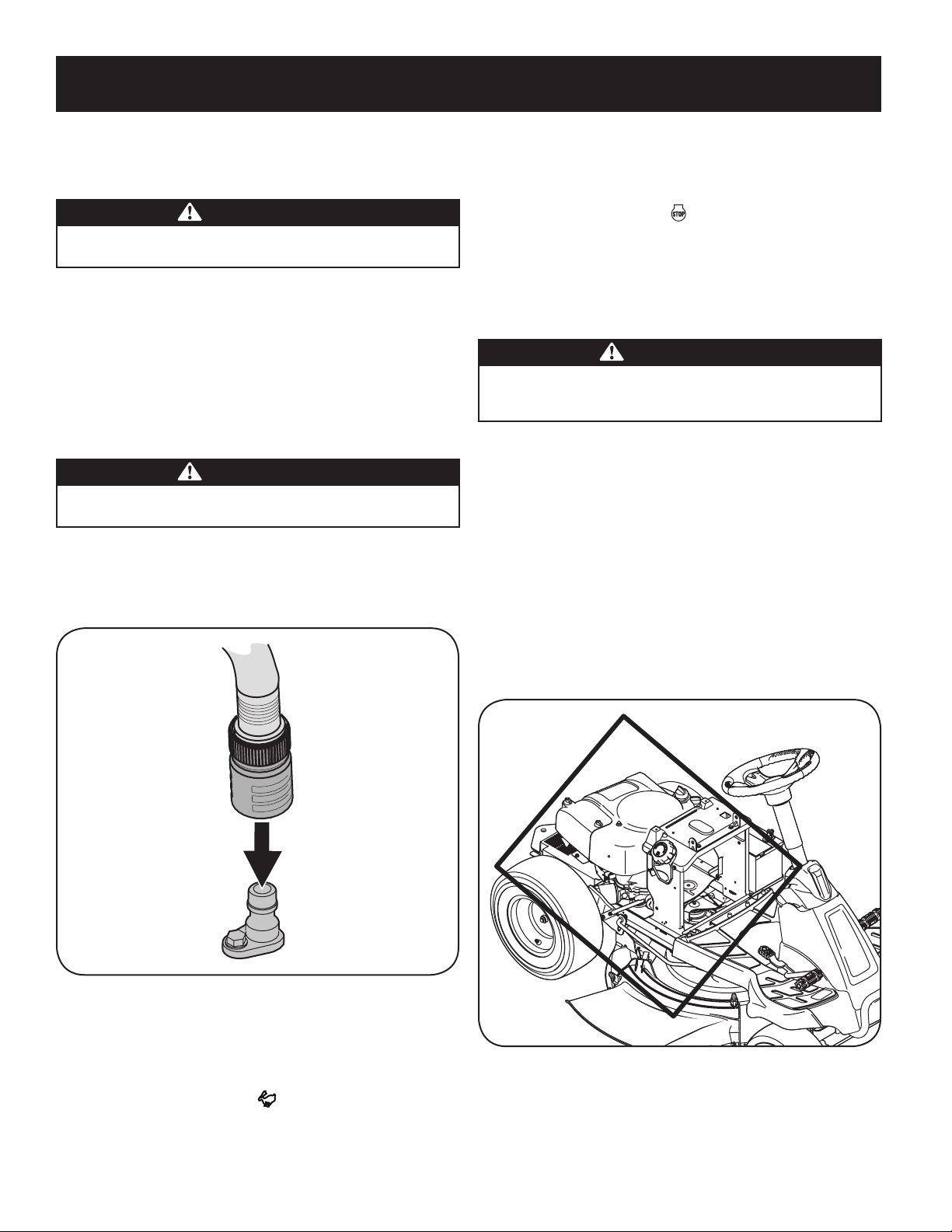
3. Thread the hose coupler (packaged with your rider’s Operator’s Manual) onto
the end of your garden hose.
4. Attach the hose coupler to the water port on your decks surface. See Figure 24.
Figure 24
Note: Make sure that the hose is not routed under the deck and is clear of all
moving parts.
5. Turn the water on.
6. While sitting in the operator’s position on the rider, start the engine and
place the throttle lever in the FAST position.
23
SERVICE AND MAINTENANCE
Storing the Rider
• Allow the machine to cool in an open area before storing.
• Do not park the rider near any flammable materials (wood, cloth or
chemicals) or any open flames or other potential source of ignition (furnace,
water heater or any other type of heater).
• Remove all combustible materials from the rider before storing. Empty cargo
boxes, grass catchers or containers.
• Always shut off fuel flow when storing or transporting if rider is equipped
with a fuel shutoff.
• Check the fuel system (lines, tank, cap and fittings) frequently for cracks or
leaks. Repair and clean as necessary.
Engine Maintenance
WARNING
Shut off the engine before performing any maintenance. To prevent
accidental start-up, disconnect the spark plug boot.
IMPORTANT: If engine must be tipped to transport equipment or to inspect or
remove grass, keep spark plug side of engine up. Transporting or tipping engine
spark plug down may cause smoking, hard starting, spark plug fouling, or oil
saturation of air cleaner.
Periodic inspection and adjustment of the engine is essential if high level
performance is to be maintained. Regular maintenance will also ensure a long
service life. The required service intervals and the kind of maintenance to be
performed are described in the table on the previous page. Follow the hourly or
calendar intervals, whichever occur first. More frequent service is required when
operating in adverse conditions.
WARNING
If the engine has been running, the muffler will be very hot. Be careful not
to touch the muffler.
Servicing the Engine Oil
• Check the oil level regularly.
• Be sure correct oil level is maintained. Check the oil every five to ten hours of
operation, before starting the engine. See Checking Oil Level in the Assembly section.
Only use high quality detergent oil rated with API service classification SF, SG,
SH, or SJ. Select the oil’s SAE viscosity grade according to the expected operating
temperature. Refer to Gas & Oil in the Assembly section of this manual.
Oil Drain
IMPORTANT: Be sure to check engine on a level surface with the engine stopped.
Drain the oil while the engine is still warm to assure rapid and complete draining.
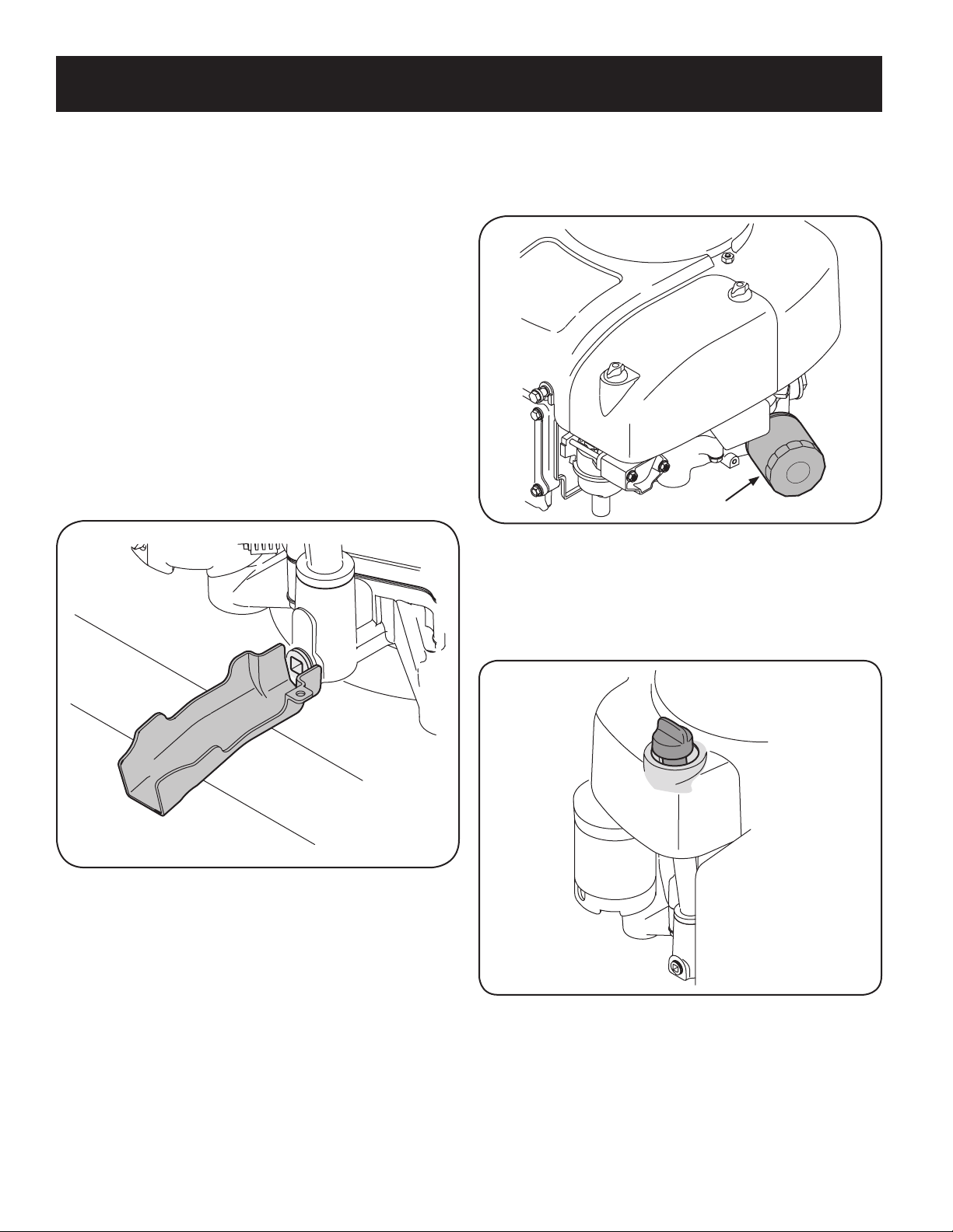
For draining oil from the engine’s crankcase of select model tractors, a plastic oil drain
sleeve is packed with this Operator’s Manual. To drain the oil, proceed as follows:
1. Unscrew the oil fill cap and remove the dipstick from the oil fill tube.
2. Snap the small end of oil drain sleeve onto the oil sump. See Figure 27.
3. Remove drain plug and drain oil into a suitable container with a capacity of
no less than 64 oz.
4. Tip the tractor slightly in the direction of the suitable container to aid in fully
draining all of the oil from the engine.
WARNING
Before tipping engine or equipment to drain oil, drain fuel from tank by
running engine until fuel tank is empty.
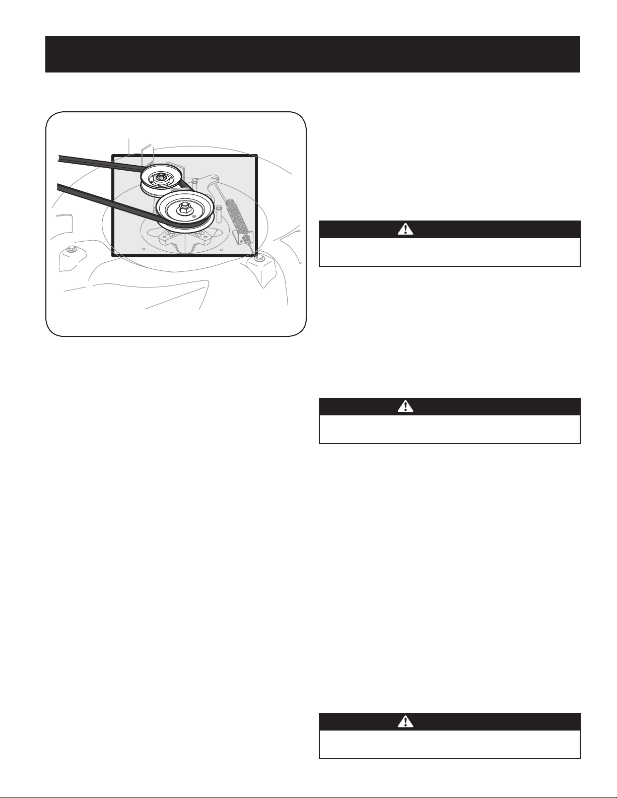
• Clean the top of the mower deck, under the spindle covers and belt area. See
Figure 26.
Figure 26
• Clean around and near the transmission, axle and the fan area. See Figure 26.
• Debris can accumulate anywhere on the rider, especially on horizontal
surfaces. Additional cleaning may be necessary when mowing in dry
conditions or when mulching.
• Fuel leaks/spills, oil leaks/spills and excess lubrication can also become
collections sites for debris. Immediate repair and cleaning up oil or fuel spills
can help reduce fire hazards.
• In addition to cleaning the rider before operating and storing, do not
attempt to mow unusually tall grass (10” or higher), dry grass (e.g., pasture)
or piles of dry leaves. Dry grass or leaves may contact the engine exhaust
and/or build up on the mower deck presenting a potential fire hazard.
Battery
Clean the battery by removing it from the riding mower and washing with a
baking soda and water solution. If necessary, scrape the battery terminals with a
wire brush to remove deposits. Coat terminals and exposed wiring with grease or
petroleum jelly to prevent corrosion.
The battery is sealed and is maintenance-free. Acid levels cannot be checked.
• Always keep the battery cables and terminals clean and free of corrosive
build-up.
• After cleaning the battery and terminals, apply a light coat of petroleum jelly
or grease to both terminals.
• Always keep the rubber boot positioned over the positive terminal to prevent
shorting.
Important: If removing the battery for any reason, disconnect the NEGATIVE
(Black) wire from it’s terminal first, followed by the POSITIVE (Red) wire.
When re-installing the battery, always connect the POSITIVE (Red) wire its
terminal first, followed by the NEGATIVE (Black) wire. Be certain that the
wires are connected to the correct terminals; reversing them could change
the polarity and result in damage to your engine’s alternating system.
24
SERVICE AND MAINTENANCE
6. Make sure dipstick is installed.
7. Start and run engine. Check for leaks.
8. Stop engine. Wait a few minutes and check the oil level. See Checking The
Oil Level in the Assembly section of this manual.
Oil Filter
Figure 28
Adding Oil
IMPORTANT: Be sure to check engine on a level surface with the engine stopped.
1. Wipe around dipstick cap and tube with a clean cloth to remove any debris.
See Figure 29.
Figure 29
2. Remove dipstick and wipe clean with a cloth.
3. Pour oil into the dipstick tube. Do not over fill. With an oil filter change the
high level amount of oil for this engine is 1700 ml (57.48 fl-oz.).
4. Install dipstick and turn to locked position before starting engine.
5. Start engine. Allow to run for a few seconds and then shut down the engine.
6. Check the oil level. See Checking Oil Level in the Assembly section of this
manual.
5. Service the Oil Filter if desired, as per the instructions later in this section.
6. Reinstall the drain plug and tighten it securely, 12-14 Nm (106.2-123.9 in-lb).
7. Remove the oil drain sleeve from the oil sump. Return the dipstick to the oil fill
tube and screw the oil fill cap back into place.
8. Pour oil into the dipstick tube. Do not over fill. With an oil filter change the high
level amount of oil for this engine is 1700 ml (57.48 fl-oz.).
9. Install dipstick and turn to locked position before starting engine.
10. Start the engine. Allow it to run for a few seconds and then shut down the
engine.
11. Check the oil level.
IMPORTANT: Used motor oil may cause skin cancer if repeatedly left in contact with
the skin for prolonged periods. Although this is unlikely unless you handle used oil
on a daily basis, it is still advisable to thoroughly wash your hands with soap and
water as soon as possible after handling used oil.
NOTE: Please dispose of used motor oil in a manner that is compatible with the
environment. We suggest you take it in a sealed container to your local service
station for reclamation. Do not throw it in the trash, pour it down a drain or on the
ground.
Figure 27
Replacing The Oil Filter
This engine is equipped with a spin-on oil filter that should be replaced each time
an oil change is performed, every season or 50 hours. Refer to Figure 28.
To replace the Oil Filter:
1. Drain the oil as instruction previously in this section.
2. Remove the oil filter. Dispose of the old oil filter properly. See Figure 28.
3. Lube gasket of new oil filter with clean oil.
4. Install and turn oil filter by hand until the gasket comes in contact with the
sealing surface of the crankcase cover, then tighten the oil filter, 10-12 Nm
(88.5-106.2 in-lb), 1/2-3/4 turn.
5. Add oil as previously instructed.
25
SERVICE AND MAINTENANCE
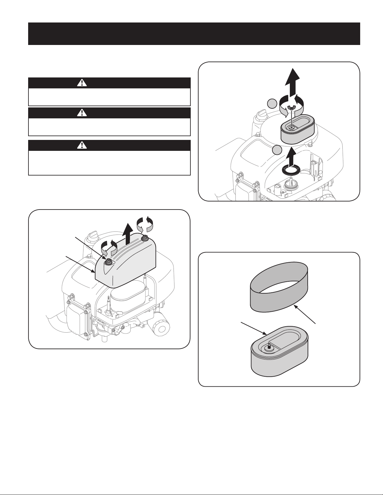
2. Remove thumb screw (A). See Figure 31.
A
B
Figure 31
3. Pull up and remove air filter and base seal (B). See Figure 31.
4. Remove the foam pre-filter from around the paper air filter. See Figure
32. Replace paper element when dirty or damaged. Clean foam element or
replace when damaged.
Air Filter
Pre-Filter
Figure 32
5. To clean foam element, wash in a mild liquid detergent and water. Squeeze
or press the foam element to rinse out dirt and water. Do not twist; this
could damage or tear the foam element. Allow to dry thoroughly before
using. DO NOT oil the foam element.
Air Filter Service
Paper filters cannot be cleaned and should be replaced every 100 operating hours;
more often if used in extremely dusty conditions.
WARNING
Never use gasoline or low flash point solvents for cleaning the air filter
element. A fire or explosion could result.
CAUTION
Do not use pressurized air or solvents to clean the air cleaner
cartridge.
WARNING
If filters, or covers are not installed correctly serious injury or death
could result from backfire. Do not attempt to start the engine with them
removed.
IMPORTANT: Never run the engine without the air filter. Rapid engine wear will
result.
1. Unscrew the thumb screws and remove the air filter cover. See Figure 30.
Air Filter Cover
Thumb Screw
Figure 30
26
SERVICE AND MAINTENANCE
Spark Plug Service
WARNING
DO NOT check for spark with spark plug removed. DO NOT crank engine with
spark plug removed.
To ensure proper engine operation, the spark plug must be properly gapped and
free of deposits.
1. Remove the spark plug boot and use a spark plug wrench to remove the
plug. See Figure 35.
WARNING
If the engine has been running, the muffler will be very hot. Be careful not
to touch the muffler.
Spark Plug
Spark Plug Boot
Figure 35
2. Visually inspect the spark plug. Discard the spark plug if there is apparent
wear, or if the insulator is cracked or chipped. Clean the spark plug with a
wire brush if it is to be reused.
3. Measure the plug gap with a feeler gauge. Correct as necessary by
bending side electrode. See Figure 36. The gap should be set to between
0.024-0.031 in.
Electrode
0.024-0.031 in.
Figure 36
6. Attach the new air filter with foam element, aligning the hole in the air filter
with the intake manifold. See Figure 33. Secure with thumb screw.
Intake Manifold
Figure 33
7. Attach the air filter cover, making sure to align plastic rib features on the
shroud to the plastic features on the air filter cover. See Figure 34. Turn
thumb screws clockwise until snug. Check for any misalignment.
Plastic Rib
Feature
Shroud
Plastic
Feature
Air Filter
Cover
Figure 34
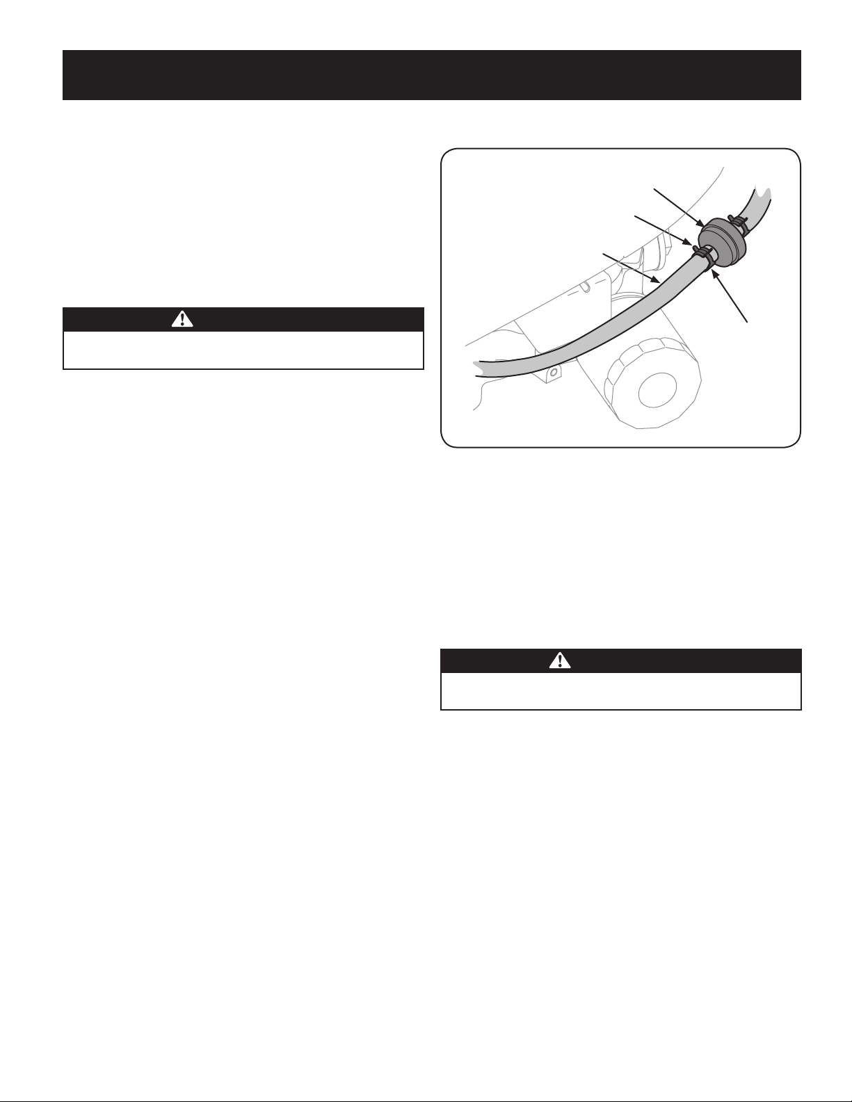
27
SERVICE AND MAINTENANCE
4. Check that the spark plug washer is in good condition and thread the spark
plug in by hand to prevent cross-threading.
5. After the spark plug is seated, tighten with a spark plug wrench to compress
the washer.
NOTE: When installing a new spark plug, tighten 1/2 turn after the spark
plug seats to compress the washer. When reinstalling a used spark plug,
tighten 1/8-1/4 turn after the spark plug seats to compress the washer.
IMPORTANT: The spark plug must be securely tightened. An improperly
tightened spark plug can become very hot and may damage the engine.
Fuel Filter Service
WARNING
Gasoline and its vapors are extremely flammable and explosive. Fire or
explosion can cause severe burns or death.
• Keep gasoline away from sparks, open flames, pilot lights, heat, and other
ignition sources.
• Check fuel lines, tank, cap, and fittings frequently for cracks or leaks. Replace
if necessary.
• Before replacing the fuel filter, drain the fuel tank as in To Drain the Fuel.
• Do not drain fuel when the engine is hot. Allow the engine adequate time to
cool. Drain fuel into an approved container outdoors, away from open flame.
• Drain any large volume of fuel from the tank by disconnecting the fuel line
from the in-line fuel filter near the engine.
• Remove the fuel line from the ln-line side (side towards the fuel tank) of the
fuel filter.
• Replacement parts must be the same and installed in the same position as
the original parts.
• If fuel spills, wait until it evaporates before starting engine.
• Before replacing the fuel filter, drain the fuel tank. Otherwise, fuel can leak
out and cause a fire or explosion.
To Drain The Fuel:
1. Locate the fuel filter, which is routed on the left side of the engine between
the fuel tank and the carburetor, and may be attached to the engine with a tie
strap. Cut the tie strap, if present, then pinch the in-line clamp on the fuel filter
with a pair of pliers, slide the clamp up the fuel line. Pull the fuel line free from
the filter and place the open end of the line into an approved container to drain
the fuel.
To Change The Fuel Filter:
1. Use pliers to squeeze the tabs on the other clamp (the out-line side of the
fuel filter), and slide the clamp away from the fuel filter. Twist and pull the
fuel line off of the fuel filter. See Figure 37.
2. Check the fuel lines for cracks or leaks. Replace if necessary.
3. Replace the fuel filter with an original equipment replacement filter. Call
1-888-331-4569 to purchase the original equipment replacement
filter.
4. Secure the fuel lines with the clamps.
The fuel filter cannot be cleaned and should be replaced every 100 operating hours;
more often if run with old gasoline.
Fuel Filter
Fuel Line
Tab
Clamp
Figure 37
Clean Engine
If the engine has been running, allow it to cool for at least half an hour before
cleaning. Periodically remove dirt build-up from engine. Clean the engine cooling
fins every 25 hours. Clean with a brush or compressed air.
IMPORTANT: Do not spray engine with water to clean because water could
contaminate fuel. Using a garden hose or pressure washing equipment can also
force water into the air cleaner or muffler opening. Water in the air cleaner will soak
the paper element, and water that passes through the element or muffler can enter
the cylinder, causing damage.
WARNING
Accumulation of debris around muffler could cause a fire. Inspect and clean
before every use.
Cutting Deck Removal
To remove the cutting deck, proceed as follows:
1. Place the PTO (Blade Engage) lever in the disengaged (OFF) position and
engage the parking brake.
2. Lower the deck by moving the deck lift lever into the bottom notch on the
right fender.
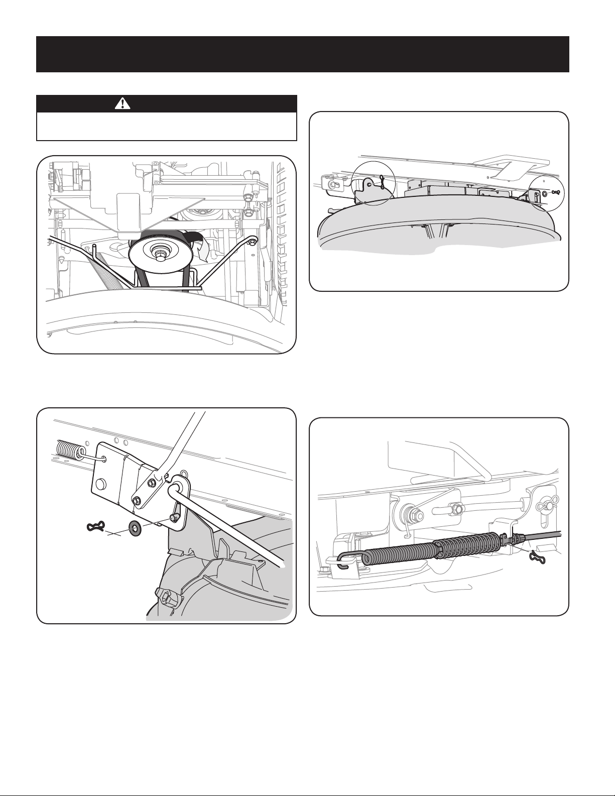
28
SERVICE AND MAINTENANCE
5. Remove the remaining bow-tie cotter pins securing the deck to the unit, as
shown in Figure 40.
Figure 40
NOTE: The bow-tie clips should be re-installed from the top down.
6. Move the deck lift lever into the top notch on the right fender to raise the
deck lift arms up and out of the way.
7. Unplug the wiring pigtail from the deck safety switch.
8. Carefully remove the PTO cable from the rear of the cutting deck by
removing the bow-tie cotter pin which secures it. Remove the spring from
the deck idler bracket. See Figure 41.
Figure 41
9. Gently slide the cutting deck (from the left side) out from underneath the
tractor.
Changing the Deck Belt
NOTE: It is possible to change the deck belt with the cutting deck still installed on
the tractor, however it is much easier to remove the deck first, change the deck belt,
then reinstall the cutting deck.
To change the cutting deck belt, proceed as follows:
3. Remove the belt from around the tractor’s PTO pulley. See Figure 38.
WARNING
Avoid pinching injuries. Never place your fingers on the idler spring or
between the belt and a pulley while removing the belt.
Figure 38
4. Remove the bow-tie cotter pin and flat washer from the deck lift assembly,
and retain for reinstallation later. See Figure 39.
Figure 39
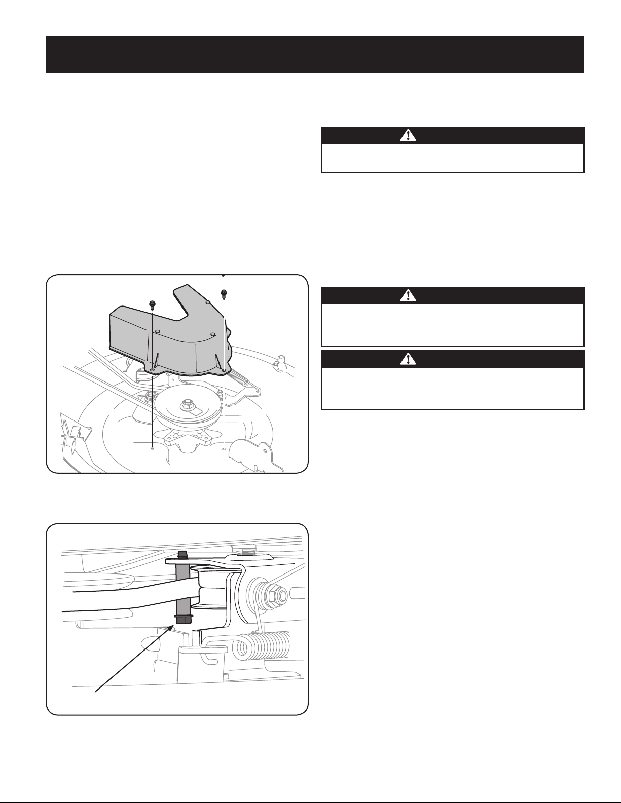
29
SERVICE AND MAINTENANCE
1. It is easiest to change the deck belt by first removing the cutting deck as
instructed earlier in this section. Skip this step if deciding to change the deck
belt with the mowing deck still installed on the unit. Otherwise, remove the
cutting deck now.
2. If changing the deck belt with the cutting deck still installed on the unit,
lower the cutting deck to the lowest cutting position.
3. Remove the deck belt from around the unit’s PTO drive pulley as shown in
Figure 38. Simply roll one side of the belt off of the pulley and then work
it off the pulley by continuing around the pulley until the belt is off of the
pulley.
4. Pull the belt towards the front of the unit, pulling it through and out of the
belt keeper bracket, shown in Figure 38.
5. Remove the deck belt cover by removing the three hex bolts that secure it.
See Figure 42.
Figure 42
6. Remove the belt keeping spacer by removing the hex bolt that secures it. See
Figure 43.
Belt Keeper Hex bolt
Figure 43
7. Change the belt, then reinstall the all the components removed in the
reverse order beginning with the idler pulley, and lastly the belt cover.
8. Feed the deck belt through the belt keeper bracket and work it around and
onto the PTO drive pulley as shown in Figure 38.
Tires
WARNING
Never exceed the maximum inflation pressure shown on the sidewall of tire.
The recommended operating tire pressure is:
• Approximately 10 psi for the rear tires
• Approximately 14 psi for the front tires
IMPORTANT: Refer to the tire sidewall for exact tire manufacturer’s recommended
or maximum psi. Do not overinflate. Uneven tire pressure could cause the cutting
deck to mow unevenly.
Cutting Blade
WARNING
Shut the engine off and remove ignition key before removing the cutting
blade for sharpening or replacement. Protect your hands by using heavy
gloves when grasping the blade.
WARNING
Periodically inspect the blade and/or spindle for cracks or damage,
especially after you’ve struck a foreign object. Do not operate the machine
until damaged components are replaced.
To remove the blade, proceed as follows.
NOTE: It may be easier to change the blade by first removing the deck from
beneath the tractor, (refer to Cutting Deck Removal earlier in this section)
then gently flip the deck over to expose its underside. It is possible to change
the blade, however, with the deck still attached to the tractor. If attempting
to change the blade with the deck still installed on the tractor, first move the
deck lift lever to its highest cutting position.
1. Remove the mulch plug, deck chute or bagging chute, if equipped, exposing
the deck chute opening.
2. Using a block of wood or 2 x 4, insert it into the deck opening and rotate the
blade around until it wedges the wood between the deck opening and the
cutting blade, as shown in Figure 44.
3. Remove the hex flange nut that secures the blade to the spindle assembly,
and remove the blade. See the Inset of Figure 44.
NOTE: The deck spindle has a normal thread. To loosen, rotate the flange lock
nut counterclockwise.
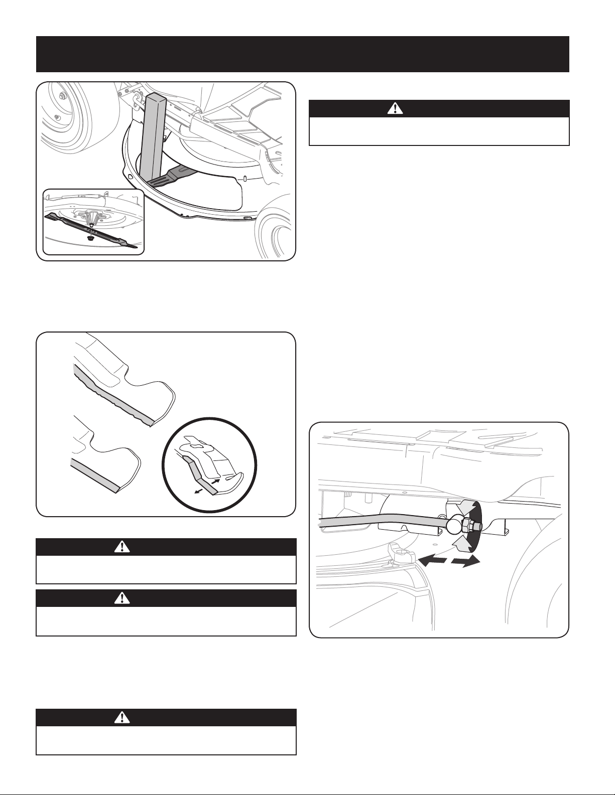
30
SERVICE AND MAINTENANCE
Figure 44
4. To properly sharpen the cutting blades, remove equal amounts of metal
from both ends of the blades along the cutting edges, parallel to the trailing
edge, at a 25°- to 30° angle. Always grind each cutting blade edge equally to
maintain proper blade balance. See Figure 45.
Figure 45
CAUTION
If the cutting edge of the blade has previously been sharpened, or if any
metal separation is present, replace the blades with new ones.
WARNING
A poorly balanced blade will cause excessive vibration, may cause damage to
the tractor and/or result in personal injury.
5. Test the blade’s balance using a blade balancer. Grind metal from the
heavy side until it balances evenly.
NOTE: When replacing the blade, be sure to install the blade with the side of
the blade marked ‘‘Bottom’’ (or with a part number stamped in it) facing the
ground when the mower is in the operating position.
CAUTION
Use a torque wrench to tighten the blade spindle hex flange nut to between
70 lbs-ft and 90 lbs-ft.
Adjustments
WARNING
Never attempt to make any adjustments while the engine is running, except
where specified in the operator’s manual.
Leveling the Deck
NOTE: Check the tractor’s tire pressure before performing any deck leveling
adjustments. Refer to Tires, in this Service And Maintenance section for more
information regarding tire pressure.
Front To Rear
It is possible to adjust the pitch of the cutting deck. The front of the deck should be
between 0” (level) and ¼” lower than the rear of the deck. Adjust if necessary as
follows:
1. With the tractor parked on a firm, level surface, place the lever for lifting the
cutting deck into the middle position (3) and rotate the blade so that it is
aligned with the front and rear of the tractor.
2. Measure the distance from the front of the blade tip to the ground and the
rear of the blade tip to the ground. The first measurement taken should be
between 0” (level) and ¼” less than the second measurement. Determine
the approximate distance necessary for proper adjustment and proceed, if
necessary, to the next step.
3. Locate the flange lock nut on the front end of the PTO Lift Rod. See Figure 46.
• Tighten the flange lock nut to raise the front of the deck;
• Loosen the flange lock nut to lower the front of the deck.
Figure 46
Seat Adjustment
Refer to the Assembly section of this manual for seat adjustment instructions.
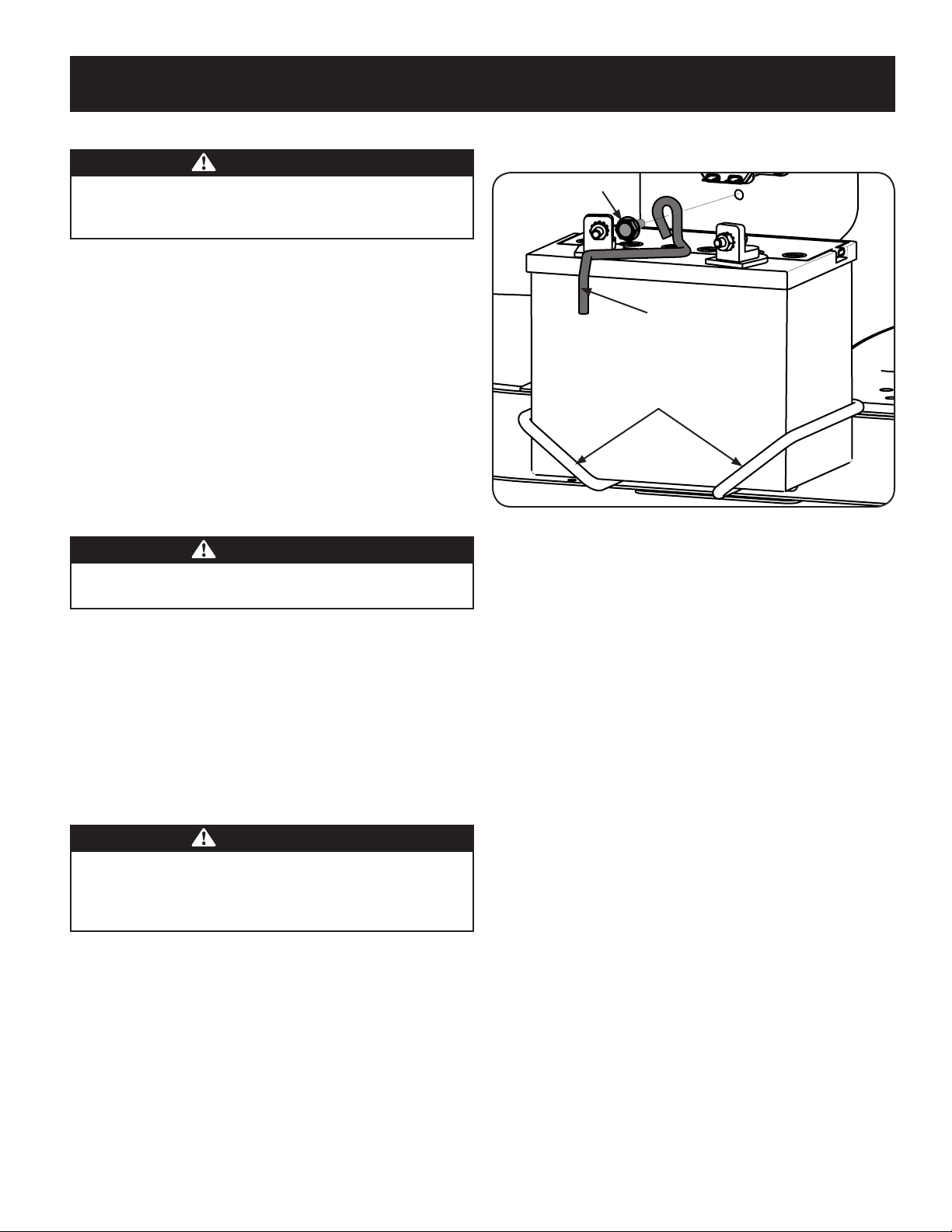
31
SERVICE AND MAINTENANCE
Parking Brake Adjustment
WARNING
Never attempt to adjust the brakes while the engine is running. Always
disengage PTO (Blade Engage Lever), move shift lever into neutral position,
stop engine and remove key to prevent unintended starting.
If the tractor does not come to a complete stop when the clutch-brake pedal is
completely depressed, or if the tractor’s rear wheels can roll with the parking brake
applied, the brake is in need of adjustment. Contact the nearest Parts & Repair
Service Center to have your brakes serviced.
To locate the nearest Parts & Repair Service Center or to schedule service,
contact 1-888-331-4569.
Changing the Transmission Drive Belt
NOTE: Several components must be removed and special tools (i.e. air/impact
wrench) in order to change the tractor’s drive belt. Contact the nearest Parts &
Repair Service Center to have your transmission drive belt serviced.
To locate the nearest Parts & Repair Service Center or to schedule service, call
1-888-331-4569.
Muffler
WARNING
Temperature of muffler and nearby engine areas may exceed 150˚ F (65˚C).
Avoid contact with these areas.
• Inspect muffler periodically, and replace if necessary. Replacement parts
for the muffler must be the same and installed in the same position as the
original parts.
Carburetor Adjustment
• The carburetor on this engine is not adjustable.
Battery
California Proposition 65 WARNING! Battery posts, terminals, and related
accessories contain lead and lead compounds, chemicals known to the State of
California to cause cancer and reproductive harm. Wash hands after handling.
CAUTION
If removing the battery, disconnect the NEGATIVE (Black) wire from its
terminal first, followed by the POSITIVE (Red) wire. When re-installing
the battery, always connect the POSITIVE (Red) wire to its terminal first,
followed by the NEGATIVE (Black) wire.
The battery is sealed and is maintenance-free. Acid levels cannot be checked.
• Always keep the battery cables and terminals clean and free of
corrosive build-up.
• After cleaning the battery and terminals, apply a light coat of
petroleum jelly or grease to both terminals.
• Always keep the rubber boot positioned over the positive terminal to
prevent shorting.
Removing the Battery
1. Locate the battery on the left side of the riding mower.
2. Remove the hex washer screw securing the battery hold-down rod to the
frame. See Figure 47.
Hex Washer Screw
Battery Hold-Down Rod
Battery Tray
Figure 47
3. With the battery hold-down rod removed, lift the battery out of the battery
tray.
4. To re-install the battery, place it back in the battery tray and secure in place
with the battery hold-down rod and hex washer screw. See Figure 47.
IMPORTANT: If removing the battery for any reason, disconnect the NEGATIVE
(Black) wire from its terminal first, followed by the POSITIVE (Red) wire. When
re-installing the battery, always connect the POSITIVE (Red) wire to its terminal
first, followed by the NEGATIVE (Black) wire. Be certain that the wires are connected
to the correct terminals; reversing them could change the polarity and result in
damage to your engine’s alternating system.
Cleaning Battery
Clean the battery by removing it from the tractor and washing with a baking soda
and water solution. If necessary, scrape the battery terminals with a wire brush to
remove deposits. Coat terminals and exposed wiring with grease or petroleum jelly
to prevent corrosion.
Battery Failures
Some common causes for battery failure are:
• Incorrect initial activation
• Overcharging
• Freezing
• Undercharging
• Corroded connections
These failures are NOT covered by your tractor’s warranty.
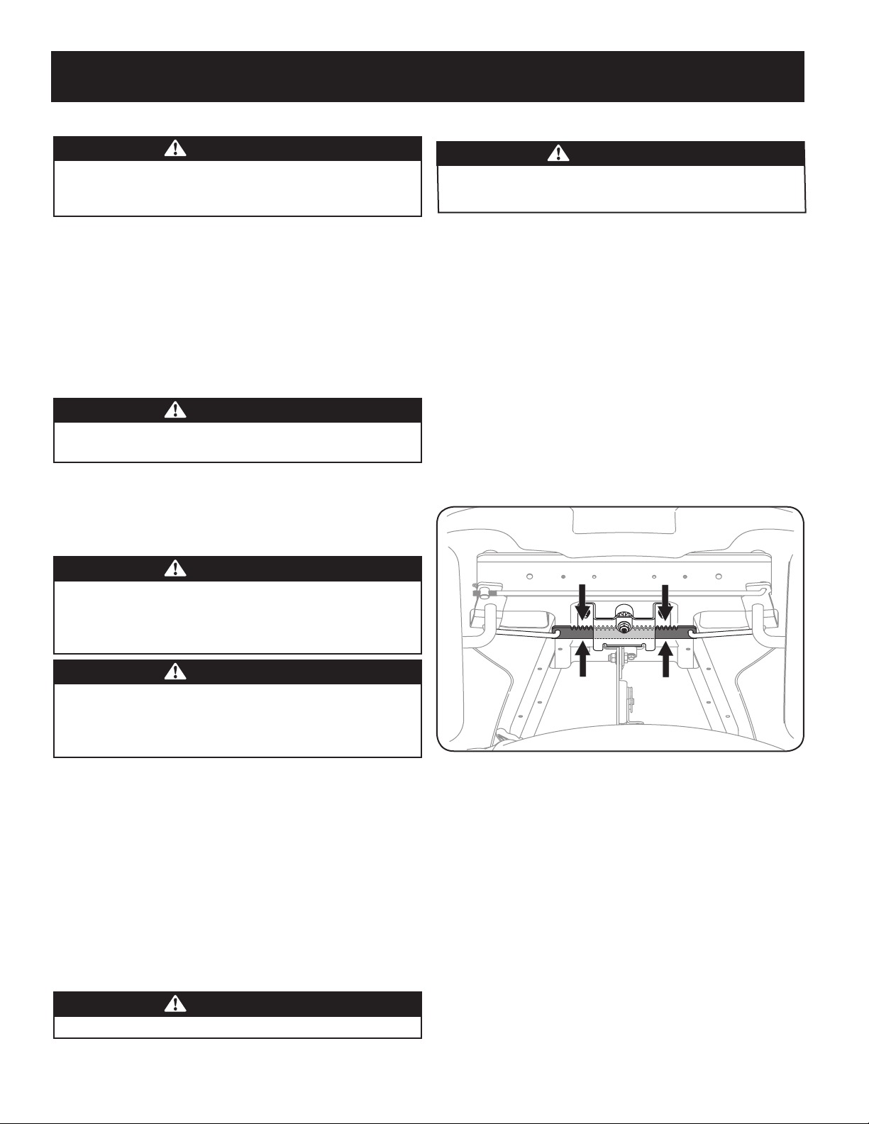
32
SERVICE AND MAINTENANCE
Jump Starting
WARNING
Never jump start a damaged or frozen battery. Be certain the vehicles
do not touch, and ignitions are off. Do not allow cable clamps to
touch.
1. Connect positive (+) cable to positive post (+) of your tractor’s discharged
battery.
2. Connect the other end of the cable to the positive (+) post of the jumper
battery.
3. Connect the second cable negative (–) to the negative post (–) of the jumper
battery.
4. Connect the other end of the negative cable to the engine block of the
tractor, away from the battery. Attach to an unpainted part to assure a good
connection.
WARNING
If the jumper battery is installed on a vehicle (i.e. car, truck), do NOT start
the vehicle’s engine when jump starting your tractor.
5. Start the tractor (as instructed in the Operation section of this manual).
6. Set the tractor’s parking brake before removing the jumper cables, in reverse
order of connection.
Charging
WARNING
Batteries give off an explosive gas while charging. Charge the battery in
a well ventilated area and keep away from an open flame or pilot light
as on a water heater, space heater, furnace, clothes dryer or other gas
appliances.
CAUTION
When charging your tractor’s battery, use only a charger designed for 12V
lead-acid batteries. Read your battery charger’s Owner’s Manual prior to
charging your tractor’s battery. Always follow its instructions and heed its
warnings.
If your tractor has not been put into use for an extended period of time, charge the
battery as follows:
1. Set your battery charger to deliver a max of 10 amperes.
If your battery charger is automatic, charge the battery until the charger indicates
that charging is complete. If the charger is not automatic, charge for no fewer than
eight hours.
Fuse
One 15 AMP fuse is installed in your tractor’s wiring harness to protect the tractor’s
electrical system from damage caused by excessive amperage.
If the electrical system does not function, or your tractor’s engine will not crank;
first check to be certain that the fuse has not blown. It can be found under the
fender on the left side of the unit, on the wiring harness just above the battery.
WARNING
Always use a fuse with the same amperage capacity for replacement.
Lubrication
WARNING
Before lubricating, repairing, or inspecting, always disengage PTO (Blade
Engage Lever), move shift lever into neutral position, set parking brake, stop
engine and remove key to prevent unintended starting.
Pivot Points & Linkage
Lubricate all the pivot points on the drive system, parking brake and lift linkage at
least once a season with light oil.
Rear Wheels
The rear wheels should be removed from the axles once a season. Lubricate the
axles and the rims well with an all-purpose grease before re-installing them.
Front Axles
Each end of the tractor’s front pivot bar may be equipped with a grease fitting.
Lubricate with a grease gun after every 25 hours of tractor operation.
Steering Rack & Pinion
Once per season, or every 25 hours of operation, it will be necessary to lubricate the
steering rack and pinion gear located under the front of the unit. Using standard
automotive grease, apply grease to the front side and rear side of the steering rack,
as indicated in Figure 48.
Figure 48

33
OFF-SEASON STORAGE
WARNING
Gasoline is a toxic substance. Dispose of gasoline properly. Contact
your local authorities for approved disposal methods.
3. Remove the spark plug and pour one (1) ounce of engine oil
through the spark plug hole into the cylinder. Crank the engine
several times to distribute the oil. Replace the spark plug.
4. Clean debris from around engine, under finger guard, and under,
around and behind muffler. Touch up any damaged paint, and
coat other areas that may rust with a light film of oil.
5. Store in a clean, dry and well ventilated area away from any ap-
pliance that operates with a flame or pilot light, such as a furnace,
water heater, or clothes dryer. Also avoid any area with a spark
producing electric motor, or where power tools are operated.
6. If possible, also avoid storage areas with high humidity, because
that promotes rust and corrosion.
7. Keep the engine level in storage. Tilting can cause fuel or oil
leakage.
DRAINING THE FUEL
1. Locate the fuel filter, which is located on the left side of the
engine, and may be attached to the engine with a tie strap.
2. Cut the tie strap, if present, then pinch the in-line clamp on the
fuel filter with a pair of pliers, slide the clamp up the fuel line.
3. Pull the fuel line free from the filter and place the open end of the
line into an approved container to drain the fuel.
PREPARING THE LAWN TRACTOR
1. Clean and lubricate the unit thoroughly as described in the
Lubrication instructions in the Service and Maintenance section.
2. Do not use a pressure washer or garden hose to clean your unit.
3. Store mower in a dry, clean area. Do not store next to corrosive
materials, such as fertilizer.
Removing From Storage
1. Check the oil level as described in the Assembly section of this
manual.
2. If the fuel was drained during storage preparation, fill the tank with
fresh gasoline. If you keep a container of gasoline for refueling,
make certain it contains only fresh fuel. Gasoline oxidizes and
deteriorates over time, causing hard starting.
3. If the cylinder was coated with oil during storage preparation, the
engine will smoke briefly at startup. This is normal.
WARNING
Never store lawn tractor with fuel in tank indoors or in poorly
ventilated areas where fuel fumes may reach an open flame, spark,
or pilot light as on a furnace, water heater, clothes dryer, or gas
appliance.
PREPARING THE ENGINE
IMPORTANT: Fuel left in the fuel tank during warm weather deterio-
rates and will cause serious starting problems.
CAUTION
Failure to use a fuel stabilizing additive or completely run the engine
until it’s out of fuel before off-season storage may result in damage to
your engine’s carburetor. Subsequent damage would not be covered
under the manufacturer’s warranty.
Engines stored between 30 and 90 days need to be treated with a
gasoline stabilizer and engines stored over 90 days need to be drained
of fuel to prevent deterioration and gum from forming in fuel system or
on essential carburetor parts. If the gasoline in your engine deterio-
rates during storage, you may need to have the carburetor, and other
fuel system components, serviced or replaced.
To prevent gum deposits from forming inside the engine’s carburetor
and causing possible malfunction of the engine, the fuel system must
be either completely emptied, or the gasoline must be treated with a
stabilizer to prevent deterioration.
1. If using a fuel stabilizer:
a. Read the product manufacturer’s instructions and recom-
mendations.
b. Add to clean, fresh gasoline the correct amount of stabilizer
for the capacity of the fuel system.
c. Fill the fuel tank with treated fuel and run the engine for 2-3
minutes to get stabilized fuel into the carburetor.
2. If emptying the fuel system:
a. Do not drain fuel when the engine is hot. Allow the engine
adequate time to cool. Drain fuel into an approved container
outdoors, away from open flame.
b. Drain any large volume of fuel from the tank by disconnect-
ing the fuel line from the in-line fuel filter near the engine.
See the complete instructions for Draining The Fuel later in
this section.
WARNING
Gasoline is extremely flammable and can be explosive under certain
conditions. Drain gasoline before storing the equipment for extended
periods. Drain fuel only into an approved container outdoors, away
from an open flame. Allow engine to cool. Extinguish cigarettes,
cigars, pipes, and other sources of ignition prior to draining fuel.
Store gasoline in an approved container in safe location.
c. Reconnect the fuel line and run the engine until it starts to
falter, then use the choke to keep the engine running until all
fuel in the carburetor has been exhausted.
d. Disconnect the fuel line and drain any remaining gasoline
from the system.

34
TROUBLESHOOTING
Problem Cause Remedy
Engine fails to start 1. PTO/Blade Engage lever engaged.
2. Parking brake not engaged.
3. Spark plug wire(s) disconnected.
4. Throttle/Choke control lever not in correct
starting position.
5. Choke not activated
6. Fuel tank empty, or stale fuel.
7. Blocked fuel line.
8. Faulty spark plug(s).
9. Engine flooded.
10. Blown Fuse(s).
11. Safety switch(s) not properly engaged.
1. Place lever in disengaged (OFF) position.
2. Engage parking brake.
3. Connect wire(s) to spark plug(s).
4. Place Throttle/Choke lever into the FAST position.
5. Move the Throttle/Choke lever into the Choke
position.
6. Fill tank with clean, fresh (less than 30 days old) gas.
7. Replace the fuel line and replace fuel filter.
8. Clean, adjust gap or replace plug(s).
9. Crank engine with throttle in FAST position.
10. Replace Fuse(s)
11. Ensure seat is in the proper operating position, and/
or deck chute, tube or mulch plug properly installed.
Engine runs erratically 1. Unit running with CHOKE activated.
2. Spark plug wire(s) loose.
3. Blocked fuel line or stale fuel.
4. Vent in gas cap plugged.
5. Water or dirt in fuel system.
6. Dirty air cleaner.
1. Deactivate the CHOKE.
2. Connect spark plug wire(s).
3. Replace the fuel line; fill tank with clean, fresh
gasoline and replace fuel filter.
4. Clear vent or replace cap if damaged.
5. Drain fuel tank. Refill with clean, fresh gasoline.
6. Replace air cleaner paper element or clean foam
pre-cleaner, if equipped.
Engine overheats 1. Engine oil level low.
2. Air flow restricted.
1. Fill crankcase with proper amount and weight of oil.
2. Clean grass clippings and debris from around the
engine’s cooling fins and housing.
Engine hesitates at high RPM 1. Spark plug gap too close. 1. Remove spark plug and reset the gap.
Engine idles rough 1. Spark plug fouled, faulty or gap too wide.
2. Dirty air cleaner.
1. Replace spark plug. Set plug gap.
2. Replace air cleaner element and/or clean pre-
cleaner.
Excessive vibration 1. Cutting blade loose or unbalanced.
2. Damaged or bent cutting blade.
1. Tighten blade and spindle.
2. Replace blade.
Mower will not mulch grass 1. Engine speed too low.
2. Wet grass.
3. Excessively high grass.
4. Dull blade.
1. Place throttle in FAST (rabbit) position.
2. Do not mulch when grass is wet.
3. Mow once at a high cutting height, then mow again
at desired height or make a narrower cutting swath.
4. Sharpen or replace blade.
Uneven cut 1. Deck not leveled properly.
2. Dull blade.
3. Uneven tire pressure.
1. Perform side-to-side deck adjustment.
2. Sharpen or replace blade.
3. Check tire pressure in all four tires.

35
Notes Page
This page intentionally left blank. Use this page to make any notes regarding your tractor.