owner's
Model No,
502.270210
CAUTION:
Read And Follow
All Safety Rules
And Instructions
Before Operating
This Equipment.
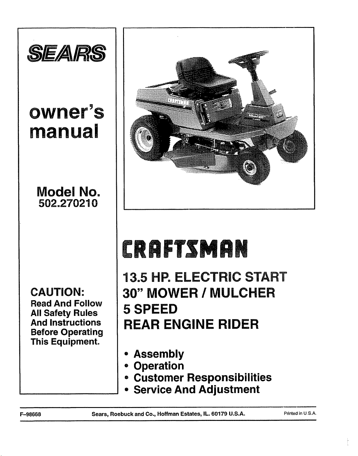
13.5 HP. ELECTRIC START
30" MOWER / MULCHER
5 SPEED
REAR ENGINE RIDER
• Assembly
• Operation
° Customer Responsibilities
° Service And Adjustment
Printed in U S,,A.
............... ii
F-98668 Sears, Roebuck and Co., Hoffman Estates, IL. 60179 U.S.A°
TABLE OF CONTENTS
WARRANTY. .........................................
CUSTOMER RESPONSIBILITIES ......................
PRODUCT SPECIFICATIONS .........................
SAFETY RULES .....................................
RESPONSIBILITY OF THE OWNER ....................
ACCESSORIES AND ATTACHMENTS ..................
ASSEMBLY .........................................
MAINTENANCEFREEBATTERY ...........................
HOWTOASSEMBLETHE STEERINGWHEEL ..............
HOWTO ASSEMBLE1rile HUB CAPS ......................
CHECKTHETIRES.........................................
CHECKTHEDRIVEBRAKE ................................
CHECKTHE BELTS..........................................
HOW TO INSTALL THE SEAT ............................... 10
CHECK THE LEVEL OF THE MOWER HOUSING ................ 10
OPERATION .........................................
LOCATION OF CONTROLS .................................
HOW TO USE THE THROTTLE CONTROL ...................
HOW TO USE THE ATTACHMEN_t'CLUTCH ..................
HOW TO USE THE SHIFT LEVER ............................
HOW =TOSET THE PARKING BRAKE .........................
HOW TO CHANGE THE CUTTING HEIGHT ....................
HOW TO STOP THE UNIT ........................................
HOW TO TRANSPORT THE UNIT ...............................
HOW TO OPERATE WrfH THE MOWER HOUSING ............
HOW TO OPERATE THE UNIT ON HILLS ..........................
BEFORE STARTING THE ENGINE ..............................
HOW TO START THE ENGINE ......................................
HOW TO START WITH A WEAK BATTERY .........................
HOW TO CHANGE THE MULCHER PLATE .........................
OPERATING TIPS .........................................................
MOWING AND BAGGING TIPS ......................................
MULCHING TIPS ............................................
2 CUSTOMER RESPONSIBIIJTIES ...................... 18
3 MAINTENANCE CHART _................................. 18
3 CHECK THE TIRES ........................................ 18
4 HOW TO REMOVE AND INSTALL THE BLADE ................ 19
5 HOW TO SHARPEN THE BLADE ............................... 19
HOW _O ADJUST THE ATTACHMENT CLUTCH ................. 20
6
HOW TO CHECK AND ADJUST THE DRIVE BRAKE ........... 21
7 HOW TO CHECK AND ADJUST THE CLUTCH ................ 21
8 HOW TO REMOVE THE SIDE PANEL ....................... 22
9 BATTERY SERVICE ....................................... 22
9 HOW TO CHARGE THE BATTERY ............................ 22
9 WHERE TO LUBRICATE ......................................... 23
9 HOW TO CHECK THE OIL ............................................. 24
9 HOW TO CHANGE THE OIL .......................................... 24
HOW TO CLEAN THE COOLING SYSTEM ................... 24
HOW 7'0 CHECK THE MUFFLER .......................... 24
11 HOW TO CLEAN THE AIR FILTERS ............................ 25
11 HOW TO CHECK THE SPARK PLUG .......................... 25
12 SERVICE AND ADJUSTMENT ......................... 26
12 HOW TO ADJUST THE CARBURETOR ......................... 26
12 HOW TO ADJUST THE THROTTLE CONTROL .............. 26
13 HOW TO REMOVE THE MOWER HOUSING ..................... 27
13 HOW TO iNSTALL THE MOWER HOUSING ........................... 27
13 HOW TO LEVEL THE MOWER HOUSING ......................... 28
13 HOW TO REPLACE THE MOTION DRIVE BELT .................... 29
14 HOW TO REPLACE THE MOWER DRIVE BELT ............. 30
14 HOW TO REPLACE THE FUSE ................................. 31
15 HOW TO SET THE CUTTING HEIGHT ...................... 31
t5 HOW TO CLEAN THE MOWER HOUSING .................... 31
15 FRONT WHEEL ALIGNMENT ................................... 31
16 STORAGE (OVER 30 DAYS) ......................................... 32
17 TROUBLE SHOOTING CHART ........................ 33
17 SLOPE GUIDE ....................................... 34
17 INDEX .............................................. 35
/ __ _ _ L _ . . .... . _. i,,_,i : ,,,_: _ .... •
LIMITED TWO YEAR WARRANTY "11
ON ELECTRIC START RIDING EQUIPMENT l_J
E!
For two (2) years from the date of purchase, if this riding equipment is maintained, lubricated and tuned up according to the I I
instructions in the owner s manual, Sears wUl repair or reptace, free of charge, any parts found to be defective in material or ! _1
workmanship.. II
This warranty does not cover: I l
• Expendable items which become wom during normal use, such as blades, spark plugs, air cteaners and belts_ I I
• Tire replacement or repair caused by punctures from outside objects, such as nails, thorns, stumps or'glass. I I
• Repairs necessary because of operator- abuse, negligence, improper storage or accident or the failure to maintain the I !
. equipment according to the instructions contained in the owner's manual° / I
Riding equipment used for commercial or rental purposes_ !1
II
LIMITED 90 DAY WARRANTY ON BATTERY I!
I I
For' 90 days from the date of purchase, if any battery incfuded with this riding equipment proves defective in material or ! !
workmanship and our'testing determines the battery will not hold a charge, Sears will replace the battery at no charge, l!
!i
WARRANTY SERVICE IS AVAILABLE BY RETURNING THE RIDING EQUIPMENT TO THE NEAREST SEARS SERVICE I I
CENTER/DEPARTMENT IN THE UNITED STATES. II
II
This warranty gives you specific legal rights, and you may also have other rights which may vary from state to state, il
!1
Sears, Roebuck and Co., D/871WA, Hoffman Estates, Illinois 60179 /.!1
......
F-98668 2
Congratulations on your purchase of a Sears Rider It has been
designed, engineered and manufactured to give you the best
Poss!ble dependability and performance
if you experience any problems you cannot easily remedy, please
see your nearest Sears Service Department We have competent,
welt trained technicians and the proper tools toservice or repair this
unit.
Please read and keep this manual The instructions will enableyou
to assemble and maintain your unit properly. Always observe the
"Safety Rules".,
NOTE: This unit is equipped with an intemaf Combustionengine and
must not be used on or near any unimproved forest-covered,
brush-covered or grass-covered land unless the engine's exhaust
system is equipped with a spark arrester meeting applicable local
or state laws (if any)_ If a spark arrester is used, it must be
maintained in effective working order by the operator
Inthe State of California, the above is required by law (Section 4442
of the California Public Resources Code) Other states may have
similar lawsoFederal laws apply onfederal lands See an Authorized
Service Center for a spark arrester for the muffler
CUSTOMER RESPONSIBILITIES
o
e
e
Carefully read and follow the rules for safe operation Inspect
the unit.,
Follow all the assembly instructions Carefully adjust the unit
Know howto operate all standard and accessary equipment on
the unit Makesure the operator can correctly operate the unit
Operate the unit only with guards, shields and other safety
items in place and working correctly
Complete all maintenance on the unit. Service the unit only with
authorized or approved replacement parts
See the Maintenance Chart
MAINTENANCE AGREEMENT
A Sears Maintenance Agreement is available on this uniL See the
nearest Sears Store for inforrnaliom
PRODUCT SPECIFICATIONS
Engine .................. 13,,5HP,,
Charging System ......... 3 amperes at 3600 rpm
Fuel Tank Size ........... 1 gallon
Type of Fuel ............. Unleaded Regular
Oil Capacity ...................... 32 ounces (1 quart)
Oil Type ................. Above 32 degrees SAE 30
........................................ Below 32 degrees SAE 5W30
Spark Plug (Gap 0 030") .. Champion RJ4C
Tire Air Pressure .........
Tire Air Pressure .........
All Gear Transaxle ........
Front 22 psi (See tire sidewall)
Rear 14 psi (See tire sidewall)
5 forward speeds and I reverse
Ground Speed Range ..... Forward 4.3 mph
................................ Reverse 2.1 mph
Tilt Seat ................. Tilts forward to access the battery
Mower Housing .......... Fuf]-fl0atingsuspension,oneblade
Cutting Height ........... 8 positions from 11/2to 4 inches
Blade Nut Torque ......... 30 foot-pounds (ft-lbs)
F-98668
Rear Engine Rider
Recordin the space below the sedal number and the date
ofpurchaseof this uniL
The model number and serial number are found ona decal
attached to the rear of the frame.
Model Number: 502.270210
Serial Number:
Date of Purchase:
Keep these numbers for future reference°

OWNER'S INFORMATION
SAFETY RULES
Safe Operation Practices for Ride-on Mowers
WARNING: This cutting machine is capable of amputating hands and feet and throwing objects, Failure to observe the
following safety instructions could result in serious injury or death.
I. General operation
1o Read, understand and followall instructions in the InstructionBook, on the machine, the engine and with any attachments before starting..
2.. Only allow responsible adults, who are familiar with the instructions,to operate the machine.
3.. Clear the area of objects such as rocks, toys, wire, etc_,which could be picked up and thrown by the blade.
4.. Be sure the area isclear of other people before mowing.. Stop the machine ifanyone enters the area_
5. Never carry passengers..
6.. Turn off power to the blades or any attachments before backing up_Do not mow in reverse unless absolutely necessary_ Always look
down and behind before and while backing_
7, Be aware ofthe mower discharge direction and donot point it atanyone. Do notoperate the mower without either the entire grassbagger
or the mower guard in place,
8. Slow downbefore turning.
9_ Never leave a machine unattended withthe engine running,,Always turnoff the blade(s), set the parkingbrake, stopthe engine and
removethe key beforedismounting.
10.. Turn off powerto attachment(s) when transporting or not in use,.Turnoff the blade(s) when not mowing,
11., Stop the engine beforeremovingthe grass bagger or unclogging the chute.
12. Mow only in daylightor good artificiallight,
13. Do notoperate the machine while underthe influence of alcohol or drugs or'when very tired_
14,. Watch for trafficwhen operating near or crossing rpadways,
15_ Use extra cautionwhen loading or unloading the machine intoatrailer'or'truck,.
16,. Always wear goggles,safety gtasses, or an eye shieldwhenyou operate theunit to protect your eyes from foreign objectsthatcan be
thrownfrom the unit°Always wear eye protection when you make an adjustment or repair to the machine,,
17,. Usecare when pullingloads or using heavy equipment.
a_.Use onlyapproved drawbar hitch points°
b. Limitloads to those you can safely control,,
co Do not turnsharply, Use care when backing_
d. Usecounterweightsor wheel weights when suggested in the instructionBook.
lB. Do notoperate thismachine if you are taking drugs or other'medicationwhichcan cause drowsiness oraffect your abilityto operate
this machine.
19. Do notuse this machine if you are mentallyor'physicallyunableto operate this machine safely.
II. Slope operation
Slopes and rough terrain are major factors related to loss-of-control and tip-over accidents, which can result in severe injury
or death. ALL slopes require extra caution. If you cannot back up the slope or if you feel uneasy on the slope, do not mow it. See
the "Slope Guide" in the back of this book to check for safe operation.
DO
1,. Mow up and down slopes, not across.,
2o Remove obstaclessuch as rocks, limbs, etc..x,
3. Watch for holes, rutsor bumps. Uneven terrain could overtum the machine. Taftgrass can hide obstacles
4. Follow the manufacturer's recommendations for wheel weights or counterweights to improve stability,,
5. Use extra care with grass baggers or other attachments, they can change the stability of the machine.,
6. Keep all movement on the slopes slow and gradual,. Do not make sudden changes in speed or direction_
7_. Avoid starting or stopping ona slope. If tires lose traction, turn off the blades and proceed slowly straight down the slope,.
DO NOT
1. Do not turn on slopes unless absolutely necessary, then only turnslowly and gradually downhill, if possible.
2, Do not mow drop-offs, ditches or embankments. A wheel over the edge or an edge caving in could cause a sudden overtumand an
injury or death._
3. Do not mow on wet grass. Reduced traction could cause sliding_
4. Do not try to stabilize the machine by putting your foot on the ground.
5. Do not use a grass bagger or other rear mounted accessories on steep slopes (greater than 10 degrees)_
111,Children
Tragic accidents can occur if the operator is not alert to the presence of chitdren. Children are often attracted to the machine and
the mowing activity, NEVER assume that children will remain where you last saw them.
1_ Keep children outofthe mowing area and in the watchfulcare of another responsible adult.
2o Be alert and rum the engine off if children enter the area.
3. Before and when backing, look behind and down for small children.
F-98668 4
OWNER'S INFORMATION
4. Never carry children or any passengers, even with the blades off,.They may fall off and be seriously injured or interfere withthe safe
operation of the machine_
5. Never allow children to operate the machine., Instruct children in the potentialdangers of the machine°
6, Use extra care when approaching blind comers, shrubs, trees or other objects thatmay obscure vision°
IV. Service
1, Use extra care when handling gasoline and other fuels Fuels are flammable and the vapors are explosive.
ao Use only an approved container_
b Never remove the gas cap or add fuel with the engine running Allow the engine tocool for several minutes before refueling Do
not smoke.
c, Never refuel the machine indoors,
d. Never store the machine with fuel in the tank or fuel container inside where there is an open flame, such as a water heater.
2_ Never start or run the engine inside a closed area,.
3, Keep all nuts and bolts, especially the blade attachment nuts tight. Frequently check the blade(s) for wear or damage suchas cracks
and nicks. A blade that is bent or damaged must be immediatelyreplaced with an original equipment blade from an authorized service
dealer, For safety, replace the blade ever/two years,, Keep the equipment in good condition,,
4. Never tamper with the safety devices. Check their proper operation regularly,
5, Toreduce fire hazards, keep the machine free of grass, leaves or other debris build-up Clean up oil or fuel spills., Allow the machine
to cool before storing,,
6,, Stop and inspect the equipment if you strike an object Repair, if necessary, before restarting,
7,, Never make adjustments or repairs with the engine running..The carburetor can be adjusted with the engine running, Do not change
the engine governor settings or over-speed the engine
8o Grass bagger components are subject to wear, damage and deterioration, which could expose moving parts or allow objects to be
thrown, For storage, always make sure the grass bag is empty,,Frequently check components and replace with manufaclurer's recom-
mended partswhennecessary.,
9, Mowerblade(s) aresharp and can cut. Wrap the blade(s) orwear gloves and use extra caution when servicing them or the bladehousing
area°
10. Check the brake operation frequently, Adjust and service as required°
11. Wait for all movement to stop before servicing any part of the uniL
Look for this symbol to indicate important safety
precautions. This symbol indicates: "Attention!
Become Alert! Your Safety Is At Risk."
RESPONSIBILITY OF THE OWNER
Environmental Awareness
- Do not fillthe engine's fuel tank completely full
o Drain fuel foroff-season storage_
- Use onlyunleaded gasoline
. Service the aircleaner reguladyo
• Change oil regularly_Use30W oil in summer.
o Tune-up the engine regularly,
• Keep equipmentinefficient operating condition_
• Dispose of used engineoilproperly
Look for this symbol to indicate important safety
precautions, This symbol indicates: "Attentionl
Become Alert! Your Safety Is At Risk."
1=-98668
ACCESSORIES AND ATTACHMENTS
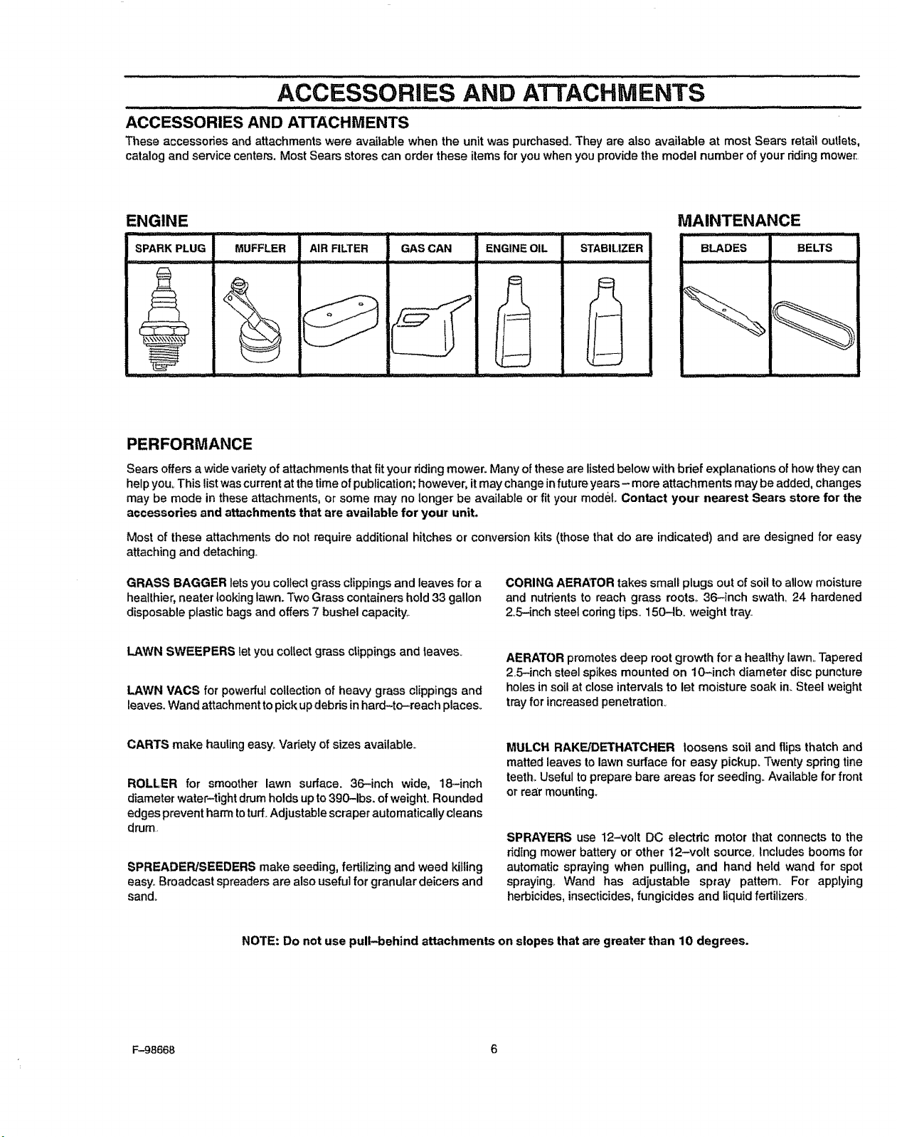
ACCESSORIES AND ATTACHMENTS
These accessories and attachments were available when the unit was purchased_They are also available at most Sears retail outlets,
catalog and service centers. MostSears stores can orderthese items for youwhen you providethe model number of your dding mower,
ENGINE MAINTENANCE
.......... ill
SPARKPLUG AIRFILTER GASCAN STABILIZER BELTS
MUFFLER
ENGINEOIL BLADES
PERFORMANCE
Sears offers a widevariety of attachments that fit your riding mower. Many of these are listed below with bdef explanations ofhow they can
help you° This listwas current at the time of publication; however, it may change in future years- more attachments may be added, changes
may be mode in these attachments, or some may no longer be available or fit your model Contact your nearest Sears store for the
accessories and attachments that are available for your unit,
Most of these attachments do not require additional hitches or conversion kits (those that do are indicated) and are designed for easy
attaching and detaching,,
GRASS BAGGER lets you collectgrass clippings and leaves for a
healthier,neater looking lawn. Two Grasscontainers hold33 gallon
disposable plastic bags and offers7 bushel capacity,
CORING AERATOR takes small plugs out of soil toallow moisture
and nutrientsto reach grass roots,, 36-inch swath_ 24 hardened
2oS-inchsteel coringtips. 150-lb. weight tray.
LAWN SWEEPERS let you collect grass clippings and leaves_
LAWN VACS for powerfulcollection of heavy grass clippings and
leaves. Wand attachmenttopickupdebrisinhard-to-roach places,
AERATOR promotes deep root growth for a healthy lawnoTapered
25-inch steel spikes mounted on 10-inch diameter disc puncture
holes in soil at close intervals to let moisture soak in. Steel weight
trayfor increased penetration°
CARTS make hauling easy,.Vadety of sizes available_
ROLLER for smoother' lawn surface. 36-inch wide, 18-inch
diameter water-tight drum holds up to 390-1bs. of weight. Rounded
edges preventharm totuff_Adjustable scraper automatically cleans
drum,
SPREADER/SEEDERS make seeding, fertilizing and weed kiIling
easy, Broadcast spreaders are alsouseful for granular deicers and
sand_
MULCH RAKE/DETHATCHER loosens soil and flips thatch and
matted leaves tolawn surface for easy pickup. Twentyspringfine
teeth°Usefultoprepare bare areas for seeding. Available for front
or rear mounting,
SPRAYERS use 12-volt DC electdc motor that connects to the
riding mower battery or other 12-volt source. Includes booms for
automatic spraying when pulling, and hand held wand for spot
spraying_ Wand has adjustable spray pattern. For applying
herbicides,insecticides,fungicides and liquid feriilizers,
NOTE: Do not use pull-behind attachments on slopes that are greater than 10 degrees.
F-98668 6
ASSEMBLY
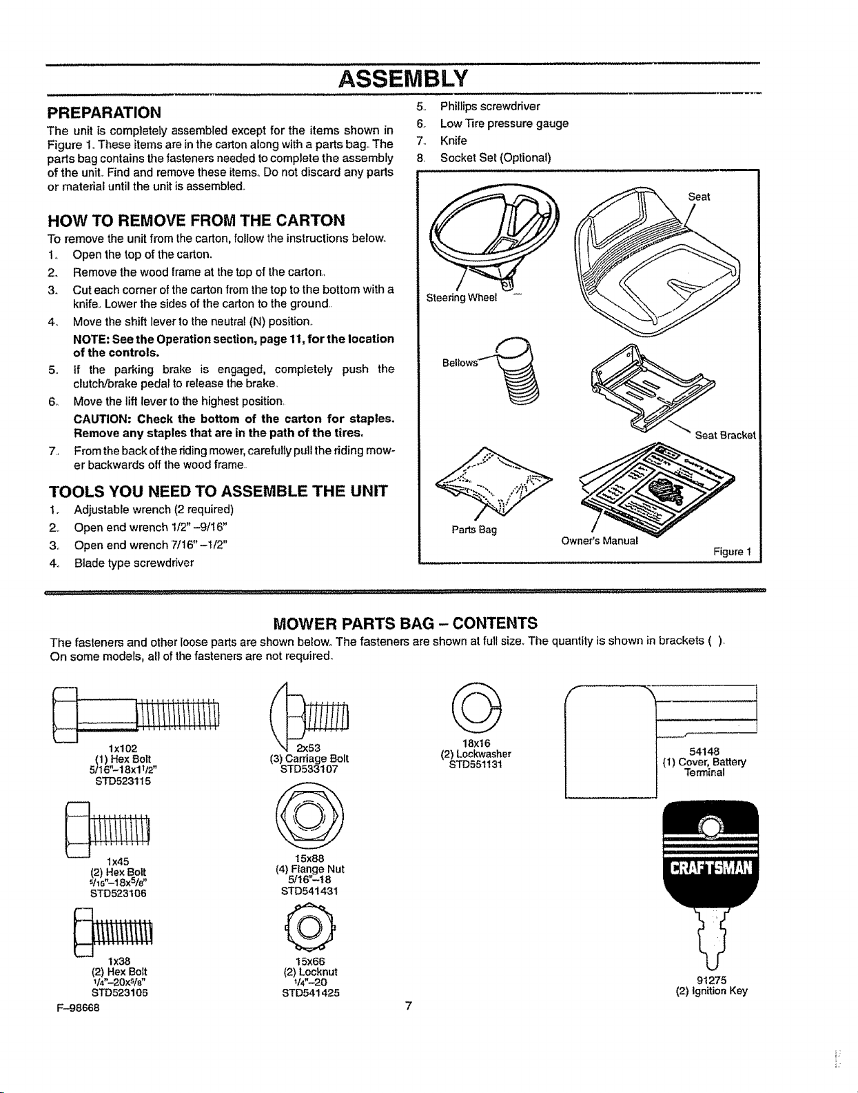
PREPARATION
The unit is completely assembled except for the items shown in
Figure 1oThese itemsare in the carton along with a parts bag. The
parts bag contains the fasteners needed to complete the assembly
of the unit. Find and remove these items.,Do not discard any parts
or matedal until the unit is assembled..
HOW TO REMOVE FROM THE CARTON
To remove the unitfrom thecarton, follow the instructions below..
1_ Open the top of the carton.
2. Remove the wood frame at the top of the carton.,
3. Cut each comer of the carton from the top to the bottom with a
knife,,Lower the sides of the carton to the ground..
4,, Move the shift lever to the neutral (N) position..
NOTE: See the Operation section, page 11,for the location
of the controls.
5., if the parking brake is engaged, completely push the
clutch/brake pedal to release the brake_
6_ Move the lift lever to the highest position,
CAUTION: Check the bottom of the carton for staples.
Remove any staples that are in the path of the tires.
7,, Fromthe back ofthe ridingmower, carefully pull the riding mow-
er backwards off thewood frame..
TOOLS YOU NEED TO ASSEMBLE THE UNIT
1. Adjustable wrench (2 required)
2,_ Open end wrench 1f2" -9/I6"
3, Open end wrench 7/16"-!/2"
4o Blade type screwdriver
5., Phillipsscrewdriver
6. Low Tire pressure gauge
7_, Knife
8 Socket Set (Optional)
SteeringWheel
Seat
SeatBracket
Pa_s Bag
Owner's Manual
Figure I
MOWER PARTS BAG - CONTENTS
The fasteners and other looseparts are shown below,,The fasteners are shown at full size_The quantityis shown in brackets (),
On some models, all ofthe fasteners are not required°
lxi02
(1) Hex Bolt
5/16".-18x11_"
STD523t15
1x45
_t2),exBo_t
16",-18X_/8
STD523106
1x38
(2) HexBolt
l14"-20x_lB"
STD523106
F-98668
18X1_6
(3) Carriage Bolt (2) Lockwasher
STD533107 STD551131
t 5x88
(4)Flange Nut
5/I6".-t 8
STD54143t
Q
15x66
(2)Locknut
V4"-20
STD541425
54148
(1) Cover,Battery
Terminal
9t 275
(2) ignition Key
MAINTENANCE FREE BATTERY
IMPORTANT: Before you attach the battery cables to the
battery, check the battery date. The battery date tells if the
battery must be charged.
1,, Check the battery date on topofthe battery (Figure 2)°
2, if tile battery is put intoservice before the battery date, the
battery cables can be attached without charging the battery.
See "How To installThe Battery Cabtes'L
3o if the battery is put into service after the battery date, the
battery must be charged. See "How To Charge The
Maintenance Free Battery"°
HOW TO CHARGE THE MAINTENANCE FREE BATTERY
_ WARNING: When you charge the battery, do not
smoke. Keep the battery away from any sparks. The
fumes from the battery acid can cause an explosion.
to Remove the battery. See"How To Remove The Battery" in the
Customer Responsibilities section,
2. Remove the protective caps from the battery terminals..
3o Use a 12 volt battery charger tocharge the battery. Charge at
a rate of 6 amperes for one hour: If you do net have a battery
charger, have an authorized service center charge the battery_
4,, tnstail the battery, See "How To Install The Battery" in the
Customer Responsibilities section.
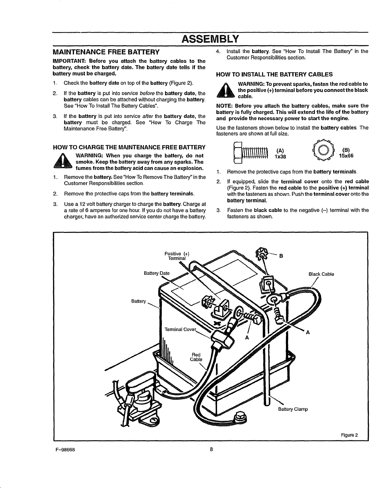
HOW TO INSTALL THE BATTERY CABLES
_ WARNING: To prevent sparks, fasten the red cable to
the positive (+) terminal before you connect the black
cable_
NOTE: Before you attach the battery cables, make sure the
battery is fully charged. This will extend the life of the battery
and provide the necessary power to start the engine°
Use the fasteners shown below toinstalithe battery cables The
fasteners areshown atfullsizeo
lx38 15x66
2.
3.,
Remove the protective caps from the battery terminals,,
If equipped, slide the terminal cover' onto the red cable
(Figure 2),.Fasten the red cable to the positive (+) terminal
with thefasteners as shown,.Push the terminal cover onto the
battery terminal°
Fasten the black cable to the negative (-) terminal with the
fasteners as shown.
Positive (+)
Terminal
Battery [ Black Cable
Battery
Terminal Cove_
Red
Cabte
A
A
Battery Clamp
Figure 2
1:-98668 8
ASSEMBLY
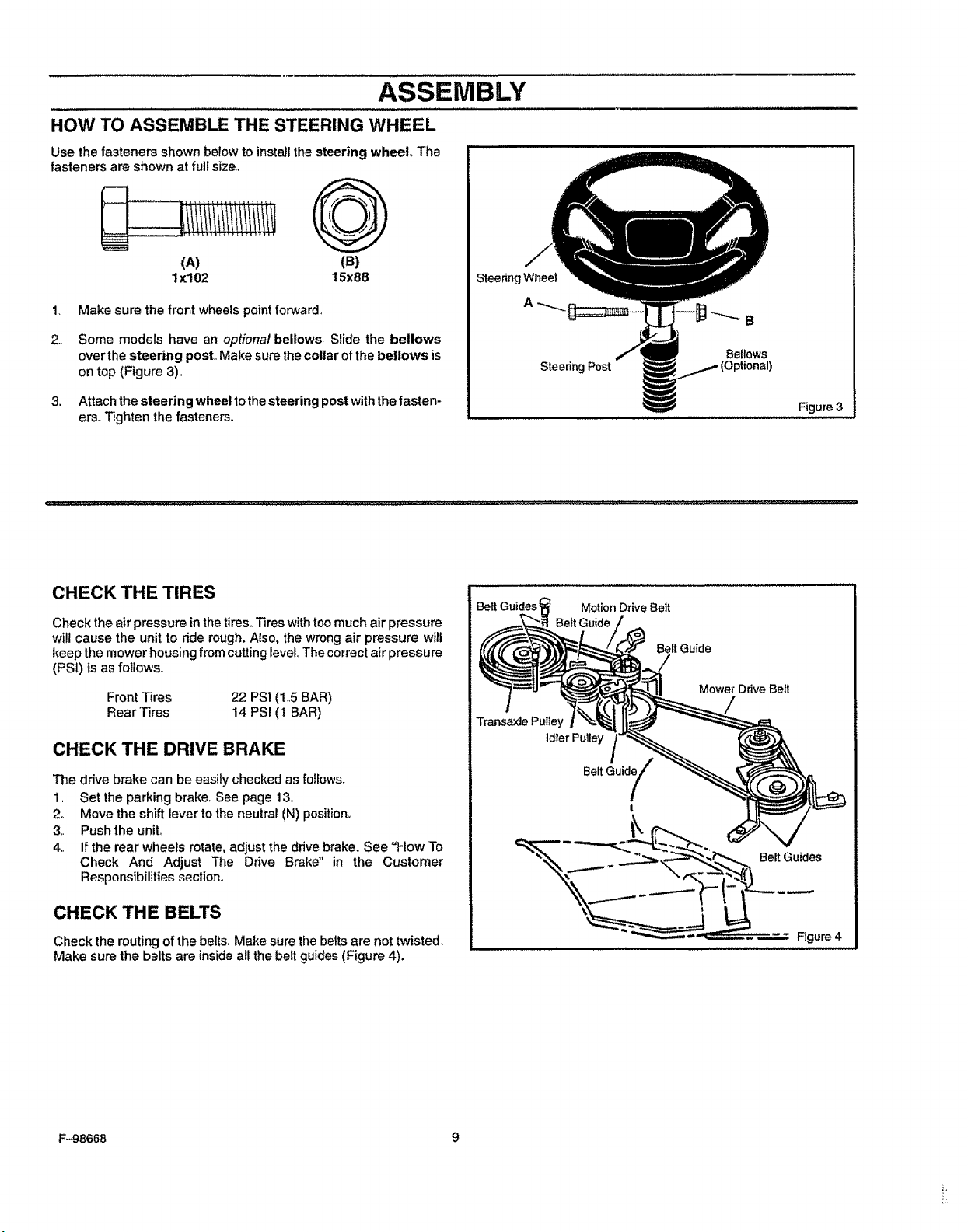
HOW TO ASSEMBLE THE STEERING WHEEL
Use the fasteners shown below to installthe steering wheel The
fasteners are shown at fullsize.,
Q
(A) (B)
lx102 15x88
1.,
3,
Make sure the front wheels pointforward.,
Some models have an optional bellows, Slide the bellows
over the steering post,,Make sure thecollar ofthe bellows is
on top (Figure 3).,
Attachthe steering wheel to the steering post withthe fasten-
ers,,Tighten the fasteners,
Steering Wheel
Steenng Post
B
Bellows
Figure 3
CHECK THE TIRES
Check the air pressure inthe tires,,Tires with toomuch air pressure
will cause the unit to ride rough. Also, the wrong air pressure wilt
keep the mower housing from cutting level, The correct air pressure
(PSI) isas follows.
Front Tires 22 PSI (1.5 BAR)
Rear Tires 14 PSI (i BAR)
CHECKTHE DRIVEBRAKE
The drive brake can be easily checked as follows_
1. Set the parking brake.,See page 13_
2o Move the shift lever to the neutral (N) position°
3., Push the unit°
4. If the rear wheels rotate, adjust the drive brake,, See "How To
Check And Adjust The Drive Brake" in the Customer
Responsibilities section,,
CHECK THE BELTS
Check the routing of the belts. Make sure thebelts are not twisted.
Make sure the belts are inside all the belt guides (Figure 4)°
Transaxle Pulley
1tiler Putley
Mower Drive Belt
- - Figure 4
F-98668 9
...............................ASSEMBLY
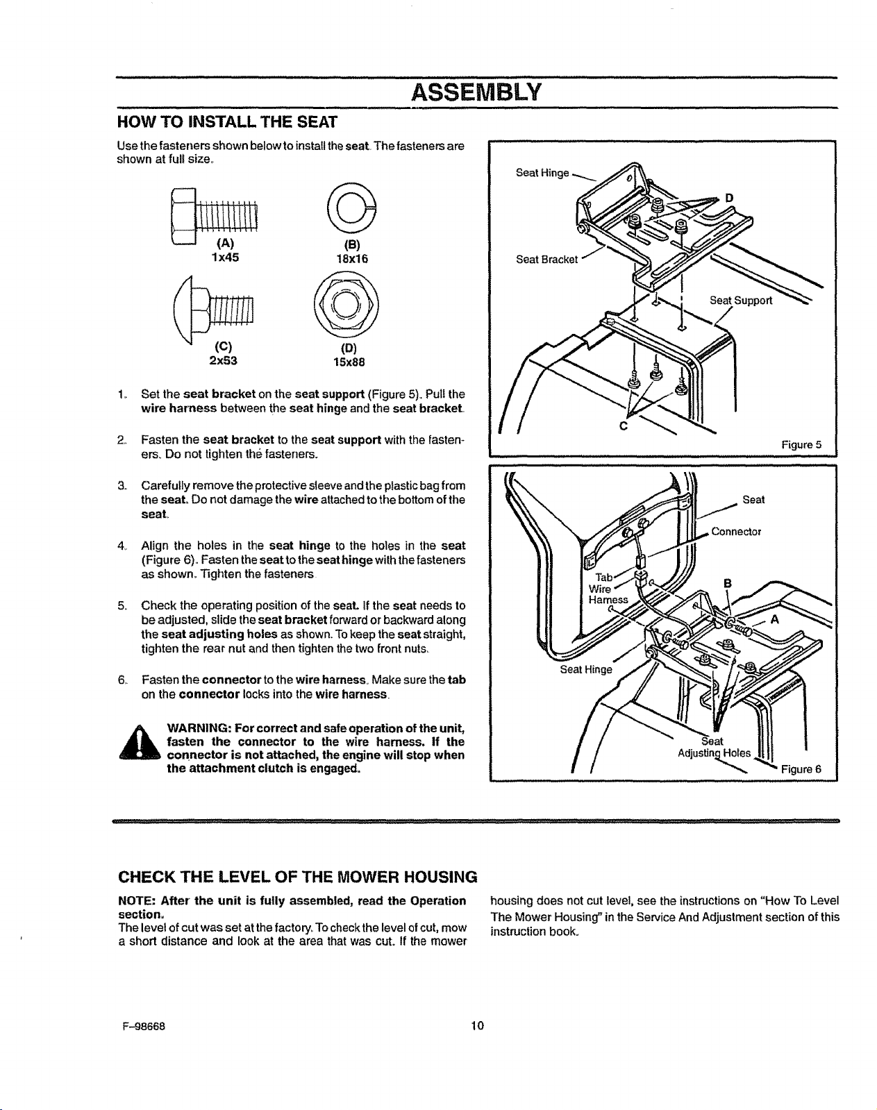
HOW TO INSTALL THE SEAT
Usethe fasteners shown belowto instal!theseal The fastenersare
shown at full size.,
2,,
iiiiii!ltti
'"(Ai ..... (S)
lx45 18x16
(D)
2x53 15x88
Set the seat bracket on the seat support (Figure 5). Pull the
wire harness between the seat hinge and the seat brackeL
Fasten the seat bracket to the seat support with the fasten-
ers_ Do not tighten the fasteners.
Seat Hinge
SeatBracket
C
Figure 5
3. Carefully remove the protectivesleeve and the plastic bag from
the seat, Do not damage the wire attached to the bottom of the
seat,.
4_ Align the holes in the seat hinge to the holes in the seat
(Figure 6).,Fasten theseat tothe seat hinge withthefasteners
as shown. Tighten the fasteners
5_
Check the operating position of the seat. if the seat needs to
be adjusted, slide the seat bracket forward or backward along
the seat adjusting holes as shown.Tokeep the seat straight,
tightenthe rear nut and then tightenthe twofront nuts.
6,, Fasten the connector to the wire harness. Make sure thetab
on the connector locksinto the wire harness.
WARNING: For correct and safe operation of the unit,
fasten the connector to the wire harness, if the
connector is not attached, the engine will stop when
the attachment clutch is engaged.
CHECK THE LEVEL OF THE MOWER HOUSING
NOTE: After the unit is fully assembled, read the Operation
section,
The level ofcut was setat the factory,.Tocheckthe levelofcut, mow
a short distance and look at the area that was cut. If the mower
housing does not cut level, see the instructions on "How To Level
The Mower Housing" in the Service And Adjustment section of this
instructionbook.
F-98668 10
OPERATION
Clutch I Brake
Pedal
Clutch
ignitionSwitch
L
Throttle Control
Lever
LiftLever
I
I
Shift Lever
Figure 7
The operation of any lawn mower can result in foreign objects thrown in the eyes, which can result in severe eye
damage. Always wear safety glasses or eye shields before starting your lawn mower and while mowing. We recom-
mend the Wide Vision Safety Mask for over the spectacles or standard safety glasses, available at Sears Retail or
Catalog Stores.
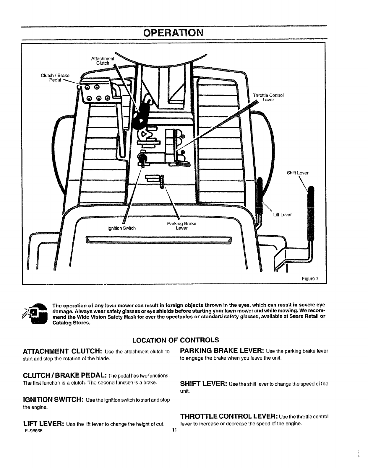
LOCATION OF CONTROLS
ATTACHMENT CLUTCH: Usethe attachment clutch to PARKING BRAKE LEVER: Usetheparkingbrake lever
start and stop the rotation ofthe blade_ to engage the brake when you leave the unit°
CLUTCH / BRAKE PEDAL: Thepedalhastwofunctions_
The first function is a clutch. The second function isa brake,
IGNITION SWITCH: Usethe ignitionswitch tostart andstop
the engine,.
UFT LEVER: Use the liftlever tochange the height ofcuL
F-98668
SHIFT LEVER: Usetheshiftlevertochangethe speed ofthe
unit.,
THROTTLE CONTROL LEVER: Use thethrottlecontrol
lever to increase or decrease the speed of the engine.
11
HOW TO USE THE THROTTLE CONTROL
Usethe throttle control to increase or decrease the speed of the
engine,.
OPERATION
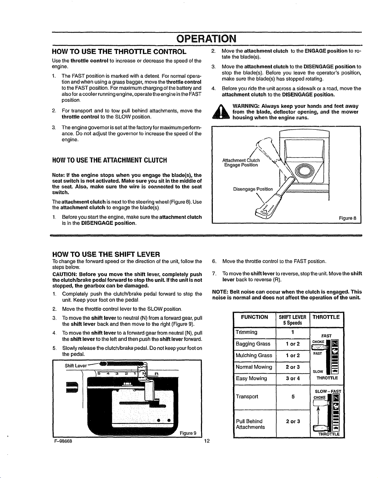
2_ Move the attachment clutch tothe ENGAGE position to ro-
tate the blade(s)o
2..
3_
The FAST position is marked with a detent For normal opera-
tion and when using a gras_ bagger; move the throttle control
tothe FAST position. For maximum charging ofthe battery and
also for acooler running engine, operate theengine inthe FAST
position.
For transport and to tow puff behind attachments, move the
throttle control to the SLOW position,,
The engine governor isset at the factory for maximum pedorm-
ance° Do not adjust the governor to increase the speed of the
engine,,
HOW TO USE THE ATTACHMENT CLUTCH
Note: if the engine stops when you engage the blade(s), the
seat switch is not activated. Make sure you sit in the middle of
the seat. Also, make sure the wire is connected to the seat
switch.
The attachment clutch isnexttothe steeringwheel (Figure 8)_Use
the attachment clutch toengage the biade(s)_
4,,
1. Before you start the engine, make sure the attachment clutch
is inthe DISENGAGE position.,
Move the attachment clutch to the DISENGAGE position to
stop the blade(s). Before you leave the operator's position,
make sure the blade(s) has stepped rotating,.
Before you ride the unit across a sidewalk or a road, move the
attachment clutch to the DISENGAGE position.
WARNING: Always keep your hands and feet away
from the blade, deflector opening, and the mower
housing when the engine runs.
Attachment Clutch
Engage Position
Disengage Position
\
Figure8
HOW TO USE THE SHIFT LEVER
Tochange the forward speed or the directionof the unit, foflow the
steps below..
CAUTION: Before you move the shift lever_completely push
the clutch/brake pedal forward to stop the unit. ifthe unitis not
stopped, the gearbox can be damaged.
1. Completely push the clutch/brake pedal forward to stop the
unit. Keep your foot on the pedal
2_
3_
4,
Move the throttle control lever' to the SLOW position
Tomove the shift lever to neutral (N) from a forwardgear, pull
the shift lever back and then move to the right (Figure 9),,
To move the shift lever to a forward gear from neutral (N), pull
the shift lever to the left and then push the shift lever forward,,
5_
ShiftLever
Slowlyrelease the clutch/brake pedal Do not keepyour foot on
the pedal.
R
F-98668
Figure 9
6. Move the throttle control to the FAST position.
7,, To move the shift lever to reverse, stop theunit. Move the shift
lever back to reverse (R).
NOTE: Belt noise can occur when the clutch is engaged. This
noise is normal and does not affect the operation of the unit.
12
FUNCTION
Tdmming
Bagging Grass
Mulching Grass
Normal Mowing
Easy Mowing
Transport
Pull Behind
Attachments
1
1 or2
1 or2
2or3
3or4
5
SHIFTLEVER
5Speeds
FAST
,ow
THROTTLE
2or3
SLOW - FAST
CHOKE
r....im
I THROTTLE
_1111111
OPERATION
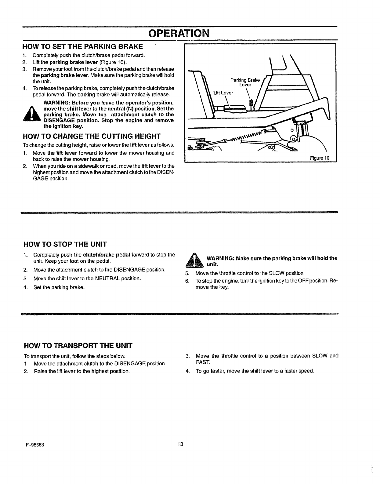
HOW TO SET THE PARKING BRAKE "
1o Completely push the clutch]brake pedal forward_
2,, Lift the parking brake lever (Figure 10).
3. Removeyourfoot from theclutchJbrakepedal and thenrelease
theparking brake lever,, Make sure the parkingbrake willhold
the unit°
4o To release theparking brake, completely push the clutch/brake
pedal forward° The parking brake willautomatically release,.
WARNING: Before you leave the operator's position,
_ move the shift lever to the neutral (N) position. Setthe
parking brake. Move the attachment clutch to the
DISENGAGE position, Stop the engine and remove
the ignition key.
HOW TO CHANGE THE CUTTING HEIGHT
Tochange thecutting height, raise or lower the lift lever as follows.
1. Move the lift lever forward to lower the mower housing and
back to raise the mower housing.,
2. When yourideon a sidewalk or road, move the lift lever tothe
highest positionand move the attachment clutchtothe DlSEN-
GAGE position.
Parking Brake
Lever
Lift Lever
Figure t0
HOW TO STOP THE UNIT
1.. Completely push the clutch/brake pedal forward to stop the
unit. Keep your foot on the pedal,
2.. Move the attachment clutchtothe DISENGAGE position,
3, Move the shift lever to the NEUTRAL position_
4. Set the parkingbrake°
_ ARNING: Make sure the parking brake will hold the
unit.
5, Move the throttle controlto the SLOW position.
6o Tostop the engine, turnthe ignitionkeytotheOFF position,Re-
move the key,
HOW TO TRANSPORT THE UNIT
To transport the unit. follow the steps below_
1. Move the attachment clutch to the DISENGAGE position
2, Raise the lift lever to the highest position,
3_ Move the throttle control to a position between SLOW and
FAST,.
4, To go faster, move the shift lever to a faster speed.
F-98668 13
........... '........OPERATION
HOW TO OPERATE WITH THE MOWER HOUSING
ii,, i i, ii
WARNING: The deflector is a safety device. Do not re-
move the deflector. The deflector forces the dis-
_ charged material toward the ground. Always keep the
deflector in the down position, if the deflector isdam-
aged, replace the deflector with an original equipment
part from an authorized service center°
1. Start the engine_
2. Move the lift lever to a height of cut position._In high or thick
grass, cut the grass in the highest position first and then lower
the mower housing to a lower position.,
& Move the throttle control to the SLOW position
4. Move the attachment clutch to the ENGAGE position
& Push the clutch/brake pedal completely forwar&
6. Move the shift lever to one of the speed setting&.
7_,
8,,
9,,
NOTE: When you mow in heavy grass or mow with a
bagger, put the shift lever in the slowest speed,
Slowlyrelease the dutch/brake pedal
Move the throttlecontrol tothe FAST position. Ifyou need to go
faster or'slower, stop the unit and move theshift lever toanother'
speed setting
Make sure the level ofcut isstill correct.. After you mow ashort
distance, look at the area that was cut. tf the mower housing
does not cut level, see the instructions on "How To Level The
Mower Housing" in the Service And Adjustment section.
WARNING: For better control of the unit, always
select a safe speed.
HOW TO OPERATE THE UNIT ON HILLS
_ WARNING: Do not ride up or down slopes that are too
steep to back straight up. Never ride the unit across
a slope° See the "Slope Guide" in the back of this
book for information on how to check slopes.
1. Before you ride up or down a hill, move the shift lever to the
slowest speed,
2, Do not stop or change speed settings on a hill. ifyou muststop,
quickly pushthe clutch!brake pedal forward and set the parking
brake.
3. To start again, make sure the shift leveris in theslowest speed,
Move the throttlecontrol to the SLOW position.,Slowly release
the pedal.
4._ If you must stop or start on a hill, always have enough space
for the unit to roll when you release the brake and engage the
clutch_
5,.
Be very careful when you change directions on a hill..When on
a slope or in a turn on a hill, move the throttle control to the
SLOW position to help prevent an accident,
F-98668 14
OPERATION
BEFORE STARTING THE ENGINE
CHECK THE OIL
NOTE: The engine was shipped from the factory filled with SAE
30 weight oil. Check the level of the oil. Add oil as needed.
1o Make sure the unitislevel,,
NOTE: Do not check the level of the oil while the engine
runs.
2. Cleanthe area around the dipstick° Remove the dipstick,.Wipe
the oil from the dipstick,
3, Insertthe dipstick intothe oil fill tube, Turn the dipstick clock-
wise until it istight.Remove the dipstick° Check the oil level on
the dipstick.,The oil level must reach the FULL mark on the
dipstick
4o If necessary, add oil until the oil reaches the FULL mark on the
dipstick.,The quantity ofoil needed from ADD to FULL isshown
on the dipstick,, Do not add too much oi!.,
ADD GASOLINE
WARNING: Always use a safety gasoline container.
Do not smoke when adding gasoline to the fuel tank.
Do not add gasoline when you are inside an enclo-
sure. Before you add gasoline, stop the engine and
let the engine cool for several minutes.
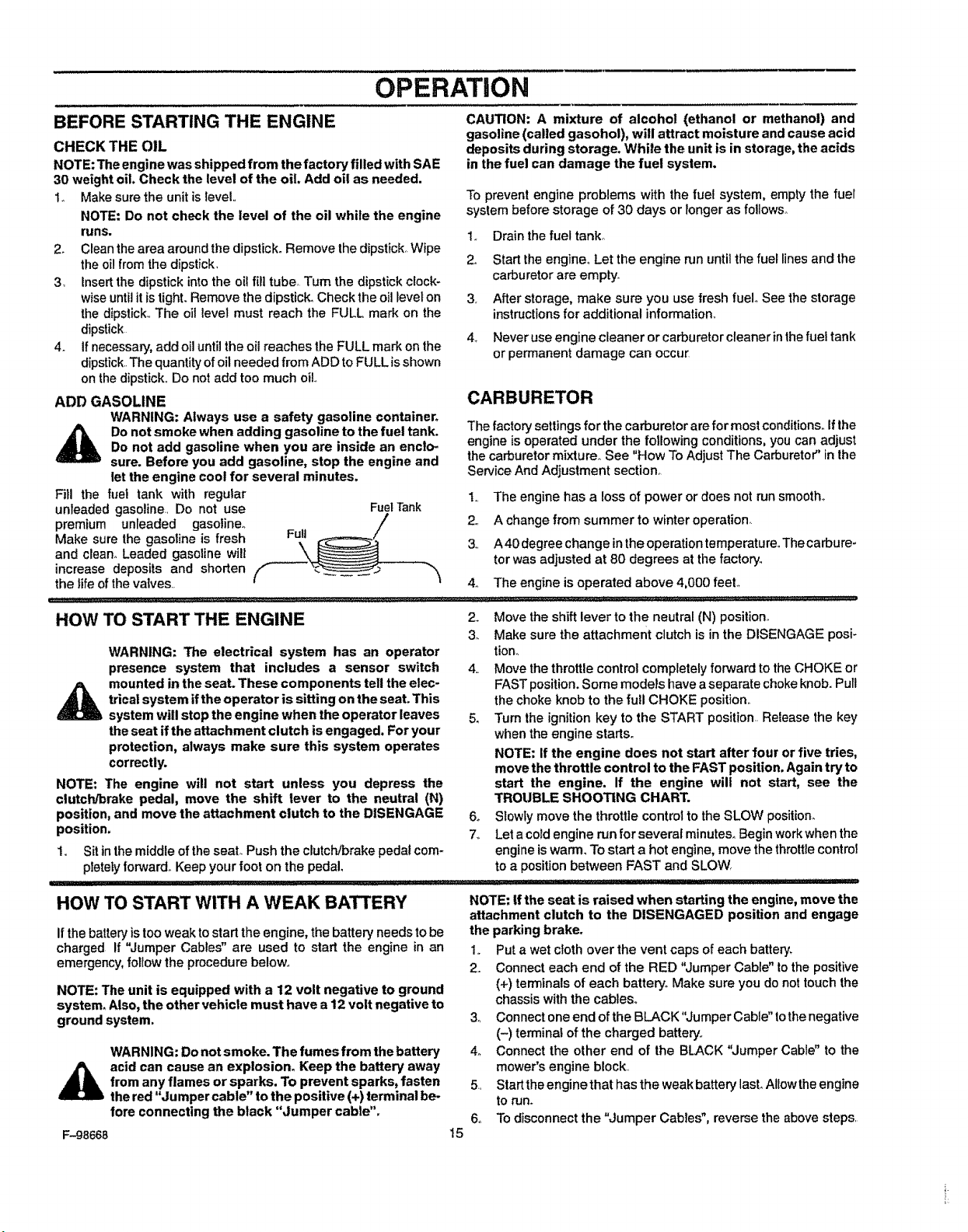
Fill the fuel tank with regular
unleaded gasoline., Do not use FuelTank
premium unleaded gasoline° Full _ /;
Make sure the gasoline is fresh
and clean. Leaded gasoline wilt
increase deposits and shorten
the life of the valves,,
CAUTION: A mixture of alcohol (ethanol or methanol) and
gasoline (called gasohol), will attract moisture and cause acid
deposits during storage. While the unit is in storage, the acids
in the fuel can damage the fuel system.
To prevent engine problems with the fuel system, empty the fuel
system before storage of 30 days or longer as follows°
1o Drainthe fueltanko
2o Start the engine° Let the engine run untilthe fuel lines and the
carburetor are empty.
3, After storage, make sure you use fresh fuelo See the storage
instructionsfor additional information,,
4_ Never use engine cleaner or carburetor cleaner in the fuel tank
or permanent damage can occur
CARBURETOR
The factory settings for the carburetor are for most conditions., if the
engine is operated under the following conditions,you can adjust
the carburetormixture. See "How To Adjust The Carburetor" in the
ServiceAnd Adjustment section_
1, The engine has a loss of power or does not run smooth°
2., A change from summer to winter operation_
3,, A40degree change in the operation temperatureoThecarbure-
tor was adjusted at 80 degrees at the factory,,
4., The engine is operated above 4,000 feel
HOW TO START THE ENGINE
WARNING: The electrical system has an operator
presence system that includes a sensor switch
_ mounted inthe seat. These components tell the elec-
trical system ifthe operator is sitting on the seat. This
system will stop the engine when the operator leaves
the seat if the attachment clutch is engaged. For your
protection, always make sure this system operates
correctly.
NOTE: The engine will not start unless you depress the
clutch!brake pedal, move the shift lever to the neutral (N)
position, and move the attachment clutch to the DISENGAGE
position.
1,, Sit in the middleof the seat,.Push the clutch/brake pedalcom-
pletelyforward. Keep your foot on the pedal
2_ Move the shift lever to the neutral (N) position°
3,, Make sure the attachment clutch is in the DISENGAGE posi-
tiono
4,, Move the throttle control completely forward to the CHOKE or
FASTposition. Some models have aseparate choke knob. Pull
the choke knob to the full CHOKE position.
5, Turn the ignitionkey to the START position,. Release the key
when the engine starts°
NOTE: If the engine does not start after four or five tries,
move the throttle control to the FAST position. Again try to
start the engine. If the engine will not start, see the
TROUBLE SHOOTING CHART.
6o Slowly move the throttle control to the SLOW position_
7_, Let acold engine run for several minutes, Begin work when the
engine is warm. To start a hot engine, move the throttle control
to a positionbetween FAST and SLOW_
IHI'IIII
HOW TO START WITH A WEAK BATTERY
If the batteryis too weak to start the engine, the battery needs to be
charged If "Jumper Cables" are used to start the engine in an
emergency,follow the procedure below,,
NOTE: The unit is equipped with a 12 volt negative to ground
system. Also,the other vehicle must have a 12 volt negative to
ground system.
WARNING: Do not smoke. The fumes from the battery
acid can cause an explosion. Keep the battery away
from any flames or sparks. To prevent sparks, fasten
the red "Jumper cable" to the positive (+) terminal be-
fore connecting the black "Jumper cable".
F-g8668
NOTE: tfthe seat is raised when starting the engine, move the
attachment clutch to the DISENGAGED position and engage
the parking brake.
Io Puta wet cloth over the vent caps of each battery,
2. Connect each end of the RED "Jumper Cable" tothe positive
(+) terminalsof each battery° Make sure you donot touch the
chassis withthe cables,
Connect oneend ofthe BLACK"Jumper Cable" tothenegative
(-) terminal ofthe charged battery,.
Connect the other end of the BLACK "Jumper Cable"to the
mower's engine block..
Startthe engine that has the weakbattery last,Allow theengine
torun.
To disconnectthe "Jumper Cables", reverse the above steps.
3_
4o
5,
6o
t5
OPERATION
i i i,i i,,, , J ,_
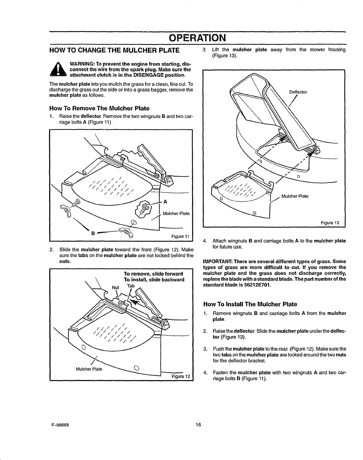
HOW TO CHANGE THE MULCHER PLATE 3v Lift the mulcher plate
(Figure 13),_
_ WARNING: lb prevent the engine from starting, dis-
connect the wire from the spark plug. Make sure the
attachment clutch is in the DISENGAGE position.
The mulcher plate lets you mulch the grass for a clean, fine cut To
discharge thegrass out the side or into a grass bagger, remove the
mulcher plate as follows.
away from the mower housing
Deflector
Mulcher Plate
F_gure t3
How To Remove The Mulcher Plate
1.. Raise the deflector. Remove the two wingnuts B and twocar-
riage bolts A (Figure 11),
\
B
A
MulcherPlate
Figure 11
SLidethe muicher plate toward the front (Figure t2)o Make
sure the tabs on themulcher plate are not locked behind the
nub_
2_
Muicher Rate
Nut
'Toremove, slide forward
To install, slide backward
4. Attach wingnutsB and carriage bolts A to the mulcher plate
for future use_
IMPOR'IANT: There are several different types of grass. Some
types of grass are more difficult to cut, If you remove the
mutcher plate and the grass does not discharge correctly,
replace the blade with astandard blade, The part number ofthe
standard blade is 56212E701.
How To install The Mulcher Plate
1. Remove wingnuts B and carriage bolts A from the mulcher
plate,
Raise thedeflector. Slide the mulcher plate underthe deflec.
tor (Figure 13).
Push the mulcher plate tothe rear, (Figure 12). Make sure the
two tabs on the mulcher plate are locked around the twonuts
for the deflector bracket,.
Fasten the mulcher plate with two wingnuts A and two car-
riage bolts B (Figure 11),.
F-98668 16
OPERATING TIPS
OPERATION
1,.
2,
3,
4,,
Check the attachment clutch for correct adjustment° For the
blade(s) to disengage correctly, the adjustment must be cop
rect
Before you use the unit, check the oil inthe engine and add oil
if necessary°
if the engine wi]! not start, first make sure the wire isattached
to the spark plug
Make sure atlthebelts are insideaitthe belt guides See the in-
structions on how to remove and install the motion drive and
mower drive belts
5
64
7,
8_
9,,
Before you make an inspection, adjustment (except for thecar-
buretor) or repair, make sure the wire from the spark plug isdis-
connected°
Make sure the seat switch wire is connected Ifthe wire is not
connected, the engine will not start
For longer life of the battery, charge the battery every three
months_
Use the shift leverto change the ground speed, not the throttle
control
Belt noise can occur when the blade or clutch isengaged° This
noise is normal and does not affect the operation of the unit
MOWING AND BAGGING TIPS
1 For a lawn to lookbetter, check the cutting level of the mower 10.
housing° See "How To Level The Mower Housing" in the Ser-
vice And Adjustment section
2,,
34
4.,
Forthe mower housing tocut level, make sure the tires have
the correct amount of air pressure (PSI)
Every timeyou usethe unit, check the blade, tf the blade isbent
or damaged, immediately replace the blade Also, make sure
the nut for the blade is tight.
Keep the blade(s) sharpened_ Worn blades will cause the ends
ofthe grass to turn brown
11o
12
13.
For better engine performance and an even discharge of the
cut grass, always operate the engine with the throttle in FAST
position
When you use a bagger, operate the engine with the throttle in
FASTposition and the shift lever in first or second gear
For better cuttingperformance and a quality cut, mow with the
shift leverin one of the slower speeds
After each use, clean the bottom and top of the mower housing
for better performance Also, a clean mower housing will help
prevent afire°
5_
6.,
7_
8,,
94
Do not cut or bag grass that is wet Wet grass will not discharge
correctly. Let the grass dry before cutting,
Use the left side of the mower housing to trim near an object
Discharge the cut grass onto the mowed area. The result is a
more even discharge of cut grass
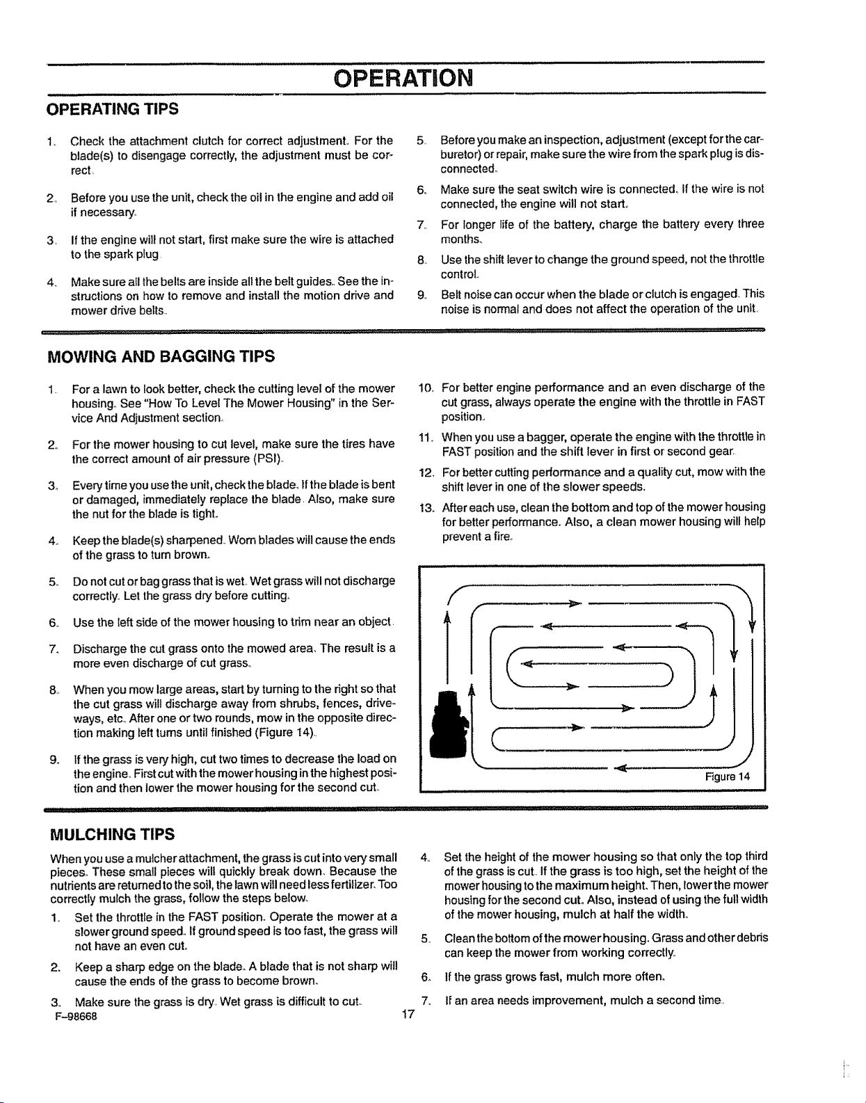
When you mow large areas, start by turning to the right so that
the cut grass wilt discharge away from shrubs, fences, drive-
ways, etc After one ortwo rounds, mow inthe opposite direc-
tion making left turns until finished (Figure 14)
Ifthe grass is very high, cut two times to decrease the load on
the engine Firstcut with the mower housing inthe highest posi-
tion and then lowerthe mower housing for the second cut
Figure14
MULCHING TIPS
When you usea mulcher attachment, the grass is cutinto very small 4
pieces° These small pieces wilt quickly break down. Because the
nutrients are returned to the soil, the lawn will need less fertilizer_Too
correctly mulch the grass, follow the steps belowo
1 Set the throttle in the FAST position. Operate the mower at a
slower ground speed If ground speed istoo fast, the grass wilt 5
not have an even cut
2. Keep a sharp edge on the blade. A blade that isnot sharp will
cause the ends of the grass to become brown_ 6.
3 Make sure the grass is dry Wet grass is difficult to cut 7
F-98668 17
Set the height of the mower housing so that only the top third
ofthe grass is cut If the grass is too high, set the height of the
mower housing to the maximum heighL Then, lower the mower
housing for the second cut. Also, instead of using the full width
of the mower housing, mulch at half the width°
Clean the bottom ofthe mower housing. Grass and otherdebris
can keep the mower from working correctty_
If the grass grows fast, mulch more often
ff an area needs improvement, mulch a second time
CUSTOMER RESPONSIBIILmES
MAINTENANCE CHART
M
0
W
E
R
EACH
PROCEDURE USE
IB_aa_iii;spectandSha_en
Attachment Clutch, Check
Brat_e,:C:heck
Clutch, Check
Tires, Check
Battery, Check and Charge
Lubrication
FIRST
2
HOURS
EVERY
25
HOURS
EVERY
50
HOURS
EVERY
100
HOURS
q
4 :.....................i ¸¸¸¸
,/
BEFORE
STORAGE
_;i ..... _ _
G
I
Oil, Check -,J
Cooling System,
Air Filter, Clean : i
Muffler, Check
Spark Plug, Check i ,
Fuel Filter; Replace (RemoteFuelTanksOnly)
,,,,,,,,,,,,........
Spark Plug, Replace:: .......:
q
i•i;ii•i:_•_i•i•:¸ii::!ii:•••!_•::•ii:•i::••:_
,..........-_i¸¸••:I:__IL_::ii•i_k•:¸:¸•:
_[;i.....: i•!::i!•i:,!!_i:_•_:
q
, _ :• _._• i I
:•i:i••:i;:•"_- _,
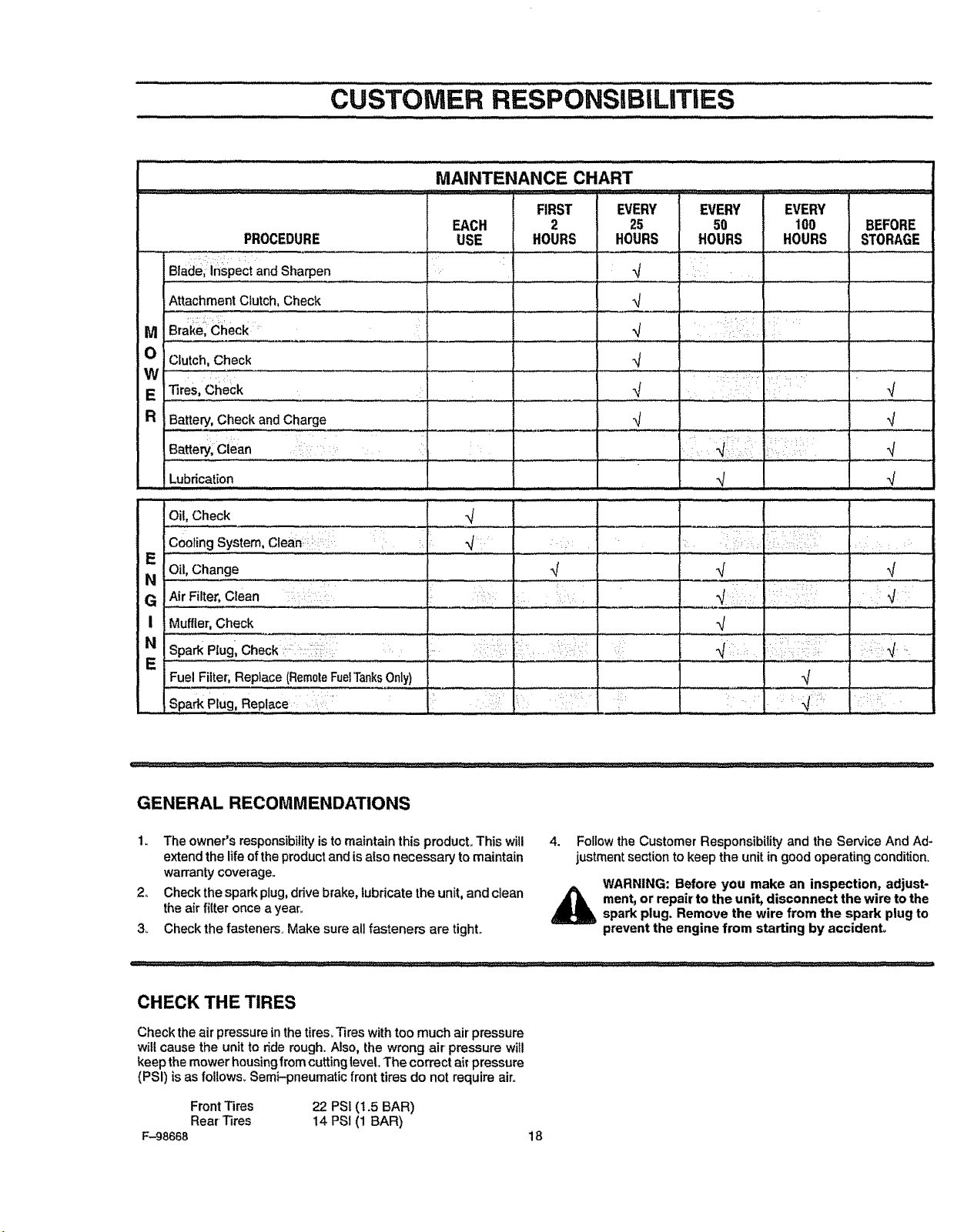
GENERAL RECOMMENDATIONS
1. The owner's responsibility isto maintain this pmducL This will
extend the life ofthe product and is also necessary to maintain
warranty coverage.
2, Check the spark plug, drive brake, lubricate the unit, and clean
the air filter once a year_
3_ Check the fasteners. Make sure all fasteners are tight.,
4. Follow the Customer Responsibility and the Service And Ad-
justment section to keep the unit in good operating condition,
WARNING: Before you make an inspection, adjust-
_ ment, or repair to the unit, disconnect the wire to the
spark plug, Remove the wire from the spark plug to
prevent the engine from starting by accident,
CHECK THE TIRES
Check the air pressure in thetires. Tires with too much air pressure
willcause the unit to ride rough. Also, the wrong air pressure will
keep the mower housing from cutting level. The correct ai_pressure
(PSI) isas foltows. Semi-pneumatic front tires do net require air.
Front Tires 22 PSI (1.5 BAR)
Rear'Tires 14 PSI (1 BAR)
F-98668 18
INSPECT BLADE
WARNING: Before you inspect or remove the blade,
disconnect the wire tothe spark plug. If the blade hits
an object, stop the engine. Check the unit for dam-
age. The blade has sharp edges. When you hold the
blade, use gloves or cloth material to protect your
hands.
If you keep the blade sharp and inspect the blade fordamage, the
blade will cut better and be more safe to operate, Frequently check
the blade for excessive wear, cracks, or other damage. Frequently
check the nut that holds the blade., Keep the nut tight If the blade
hits an object, stop the engine. Disconnect the wire tothe spark plug,,
See if the blade is bent or damaged Check the blade adapter for
damage, Before you operate the unit, replace damaged parts with
original equipment parts. See the authorized service center in your
area_ Every three years, have an authorized service person inspect
the blade or replace the ofd blade with an original equipment part,
CUSTOIVl'ER RESPONSiBILiTIES
9. Tighten the nut that holds the blade to a torque of 30 foot
pounds (41,5 N-m),
10. Install the mower housing, See "How To Install The Mower
Housing".,
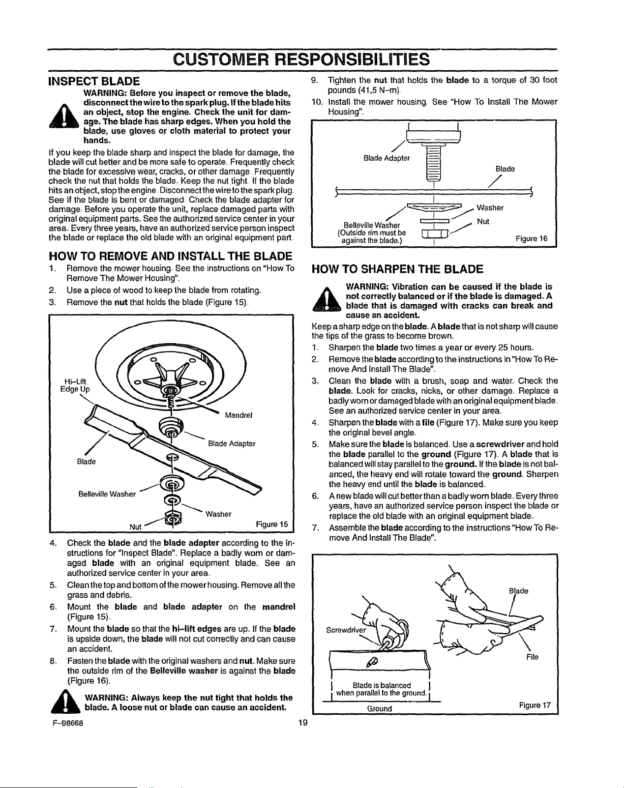
HOW TO REMOVE AND INSTALL THE BLADE
1o Remove the mower housing. See the instructions on "How To
Remove The Mower Housing".,
2., Use a piece of wood to keep the blade from rotating.,
3,, Remove the nut that holds the blade (Figure 15),
J "" Mandrel
B|ade
Blade Adapter
Figure 15
4o Check the blade and the blade adapter according to the in-
structions for "inspect Blade". Replace a badly wom or dam_
aged blade with an original equipment blade,, See an
authorized service center inyour area,,
5. Clean the top and bottom of the mower housing° Remove all the
grass and debris.
6. Mount the blade and blade adapter on the mandrel
(Figure 15)_
7o Mount the blade so that the hi-lift edges are up. If the blade
is upside down, the blade wiltnot cut correctly and can cause
an accident,
8, Fasten the blade with the original washers and nut. Make sure
the outside rim of the Belleville washer is against the blade
(Figure 16).
_ ARNING: Always keep the nut tight that holds the
blade, A loose nut or blade can cause an accident.
t:-98668
BIadeAdapter
" I
_.I Washer
Belleville Washer Nut
(Outside r_l!nmust be [_--"
against the blade,)
Blade
/
,t
I Figure16
HOW TO SHARPEN THE BLADE
WARNING: Vibration can be caused if the blade is
not correctly balanced or if the blade is damaged. A
blade that is damaged with cracks can break and
cause an accident.
Keep asharp edgeontheblade,,A blade that isnotsharp willcause
the tips of the grass to become brown.
1, Sharpen the blade two times a year or every 25 hours.
2,, Remove theblade according tothe instructions in"How ToRe-
move And Install The Blade",,
3o Clean the blade with a brush, soap and water° Check the
blade,, Look for cracks, nicks, or other damage, Replace a
badly worn or damaged blade with an original equipment blade,.
See an authorized service center in your area,,
4. Sharpen the blade with afile (Figure 17). Make sure you keep
the odginal bevel angle,
5,, Make sure theblade isbalanced Use a screwdriver and hold
the blade parallel to the ground (Figure 17),_A blade that is
balanced will stay parallel to the ground. Ifthe blade is not bal-
anced, the heavy end will rotate toward the ground,, Sharpen
the heavy end until the blade is balanced,,
6,, A new blade will cut better than a badly worn blade, Every three
years, have an authorized service person inspect the blade or
replace the old blade with an original equipment blade,.
7. Assemble the blade according to the instructions "How To Re-
move And Install The Blade",
19
Screwdnv__
t
I Bladeis balanced
,_ whenparalleltotheground_
Ground
File
Figure 17
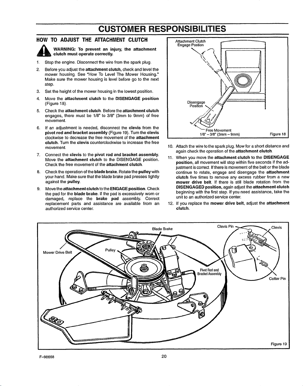
HOW TO ADJUST THE ATTACHMENT CLUTCH
...........................CUSTOMER RESPONSIBILITIES
AttachmentClutch
WARNING: To prevent an injury, the attachment
clutch must operate correctly.
1. Stop the engine.. Disconnect the wire from the spark plug
2. Before you adjust the attachment clutch, check and level the
mower housing.. See =How To Level The Mower' Housing."
Make sure the mower housing is level before go to the next
step..
3o Set the height of the mowerhousingin the lowest position..
4. Move the attachment clutch to the DISENGAGE position
(Figure 18).
5.. Check the attachment clutch Before the attachment clutch
engages, there must be I/8" to 3/8" (3mm to 9ram) of free
movemenL
6_
7_
If an adjustment is needed, disconnect the clevis from the
pivot rod and bracket assembly (Figure 19)."rumthe clevis
clockwise to decrease the free movement ofthe attachment
clutch.. Turn the clevis counterclockwiseto increase the free
movement.
9,.
EngagePost[on
Disengage
Position
10o
Connect the clevis to the pivot rod and bracket assembly,
Move the attachment clutch to the DISENGAGE position.
Check the free movement of the attachment clutch.
11,.
Check the operation of theblade brake_Rotate the pulley with
your hand. Make sure that the bladebrake pad presses tightly
against the pulley.
Move the attachment clutch tothe ENGAGE position, Check
the pad for the blade brake,. Ifthe pad isexcessively worn or
damaged, replace the brake pad assembiyo Correct
replacement parts and assistance are available from an
authorized service center,.
12.
F_eeMovement
1/8"- 318"(3ram - gram) Figure 18
Attach the wire tothe spark plug, Mow for ashort distance and
again check the operation of the attachment clutch.
When you move the attachment clutch to the DISENGAGE
position, all movement wilt stop within five seconds if the ad-
justment iscori'ect. Ifthere ismovement of the belt or the blade
continue to rotate, engage and disengage the attachment
clutch five times to remove any excess rubber from a new
mower drive belt.. If there is still blade rotation from the
DISENGAGED position, again adjust the attachment clutch
beginning with the first step. Ifyou need assistance, take the
unittoan authorized service center.
tf you replace the mower drive belt, adjust the attachment
clutch.
BladeBrake
ClevisPin
Mower Drive Bert
Pulley
PivotRodand
BrackelAssembly
Cotter Pin
Figure 19
F-98668 20
cusTOMER
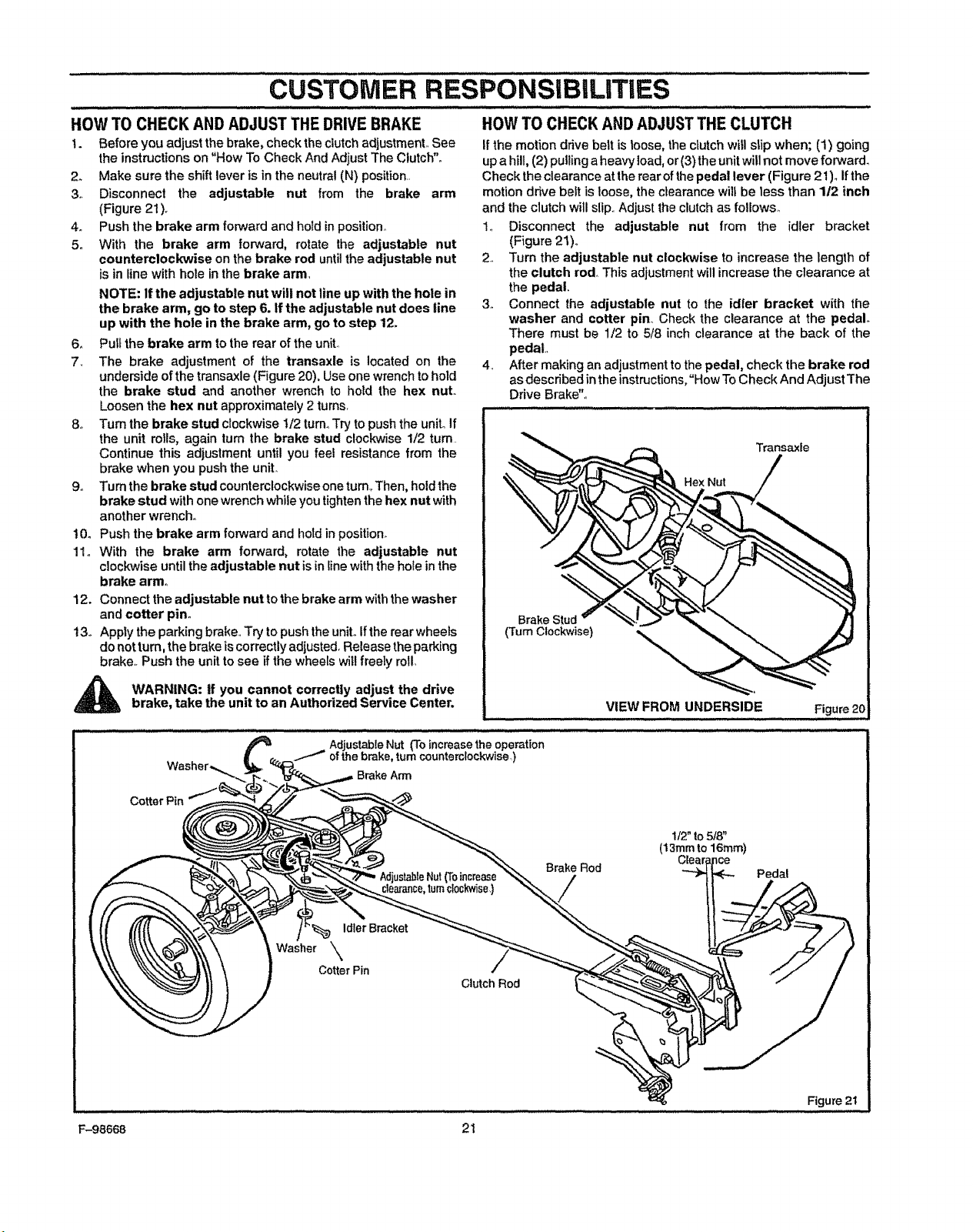
HOWTO CHECKANDADJUSTTHEDRIVEBRAKE
1. Before you adjust the brake, checkthe clutchadjustment,, See
the instructions on"How To Check And Adjust The Clutch".
2. Make sure the shift lever isin the neutral(N) position,.
3,. Disconnect the adjustable nut from the brake arm
(Figure 21),
4o Push the brake arm forward and holdinposition°
5,, With the brake arm forward, rotate the adjustable nut
counterclockwise onthe brake rod untilthe adjustable nut
is in line with hole in the brake arm,
NOTE: If the adjustable nut will not line up with the hole in
the brake arm, go to step 6. If the adjustable nut does line
up with the hole in the brake arm, go to step 12.
6. Pull the brake arm to the rear of the unit,,
7_ The brake adjustment of the transaxle is located on the
underside of the transaxle (Figure 20), Use one wrench to hold
the brake stud and another wrench to held the hex nut.
Loosen the hex nut approximately 2 turns,
8o Turn the brake stud clockwise 1/2 turn. Try to push the uniL If
the unit rolls, again turn the brake stud clockwise 1/2 turn
Continue this adjustment until you feel resistance from the
brake when you push the unit,,
9. Turn the brake stud counterclockwise one turn, Then, hold the
brake stud with one wrench while you tighten the hex nut with
another wrench°
10o Push the brake arm forward and hold in position.
11o With the brake arm forward, rotate the adjustable nut
clockwise untilthe adjustable nut isin linewith the hole inthe
brake arm°
12. Connect the adjustable nut to the brake arm withthe washer
and cotter pin°
13o Apply the parkingbrake,,Try topushthe unit°Iftherear wheels
do not turn,the brake is correctlyadiustedoRelease the parking
brake,. Push the unitto see if the wheelswillfreely roll,
WARNING: If you cannot correctly adjust the drive
brake, take the unit to an Authorized Service Center.
RESPONSIBILITIES
HOW TO CHECK AND ADJUST THE CLUTCH
If the motion drive belt isloose, the clutchwillslip when; (1) going
up a hill, (2) pullingaheavy load,or (3)the unit will not move forward.
Check the clearance at the rear ofthepedal lever (Figure 21)o ifthe
motion drive belt is loose, the clearance will be less than 1/2 inch
and the clutch willslip.,Adjust the clutchas follows,,
1., Disconnect the adjustable nut from the idler bracket
(Figure 21),,
2, Turn the adjustable nut clockwise to increase the length of
the clutch rod° This adjustment will increase the clearance at
the pedal.
3, Connect the adjustable nut to the idler bracket with the
washer and cotter pin., Check the clearance at the pedal°
There must be 1/2 to 5/8 inch clearance at the back of the
pedal,
4. After making an adjustmenttothe pedal, check the brake rod
asdescribed inthe instructions,"How To Check And Adjust The
Drive Brake",,
Transaxle
Hex Nut
Brake
(Turn Clockwise)
VIEW FROM UNDERSIDE
Figure 20
Cotter Pin
Adjustable Nut (To increase the operation
ofthe brake, turn counterclockwise)
Brake Arm
} increase
turncl0ckwise,)
Brake Rod
1t2" to518"
(13ram to 16ram)
Clea _ce
Pedal
Idler Bracket
Washer _\\
Cotter Pin
Clutch Rod
Figure 2t
F-98668 21
CUSTOMER RESPONSiBiLiTiES
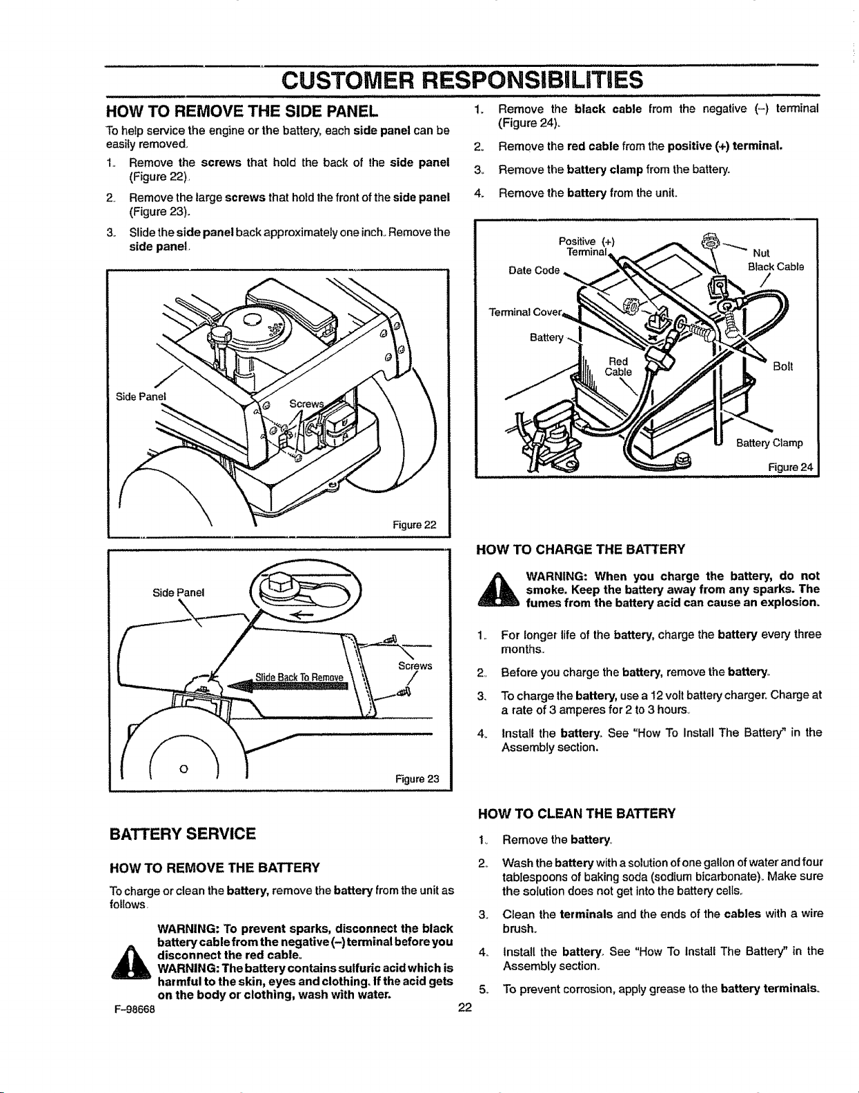
HOW TO REMOVE THE SIDE PANEL
To help service the engine or the battery, each side panel can be
easily removed.
1.. Remove the screws that hold the back of the side panel
(Figure 22).
2. Remove the large screws that hold the front ofthe side panel
(Figure 23).
3. Slide the side panel back approximately one inch,,Remove the
side panel,
J
SidePanel
Figure 22
1. Remove the black cable from the negative (-) terminal
(Figure 24)°
2o Remove the red cable from the positive (+) terminal.
3o Remove the battery clamp from the battery.
4. Remove the battery from theunit.
Positive (+)
Terminal
Date Code,
Terminal Cover,
Nut
BlackCable
/
Bolt
BatteryClamp
Figure24
HOW TO CHARGE THE BATTERY
Side Panel
Screws
/
Figure 23
WARNING: When you charge the battery, do not
smoke. Keep the battery away from any sparks. The
fumes from the battery acid can cause an explosion=
For longer life ofthe battery, charge the battery every three
months,,
2, Before you charge the battery, removethe battery_
3. To charge the battery, usea 12voltbatterycharger. Charge at
a rate of3 amperes for 2 to 3 hours.,
4,, Install the battery° See "How To Install The Battery" in the
Assembly section.
BATTERY SERVICE
HOW TO REMOVE THE BATTERY
Tocharge orclean the battery, remove thebattery from the unitas
fol{ows.
WARNING: To prevent sparks, disconnect the black
batterycablefromthe negative (-) terminal before you
_ disconnect the red cable°
WARNING: The battery contains sulfuric acid which is
harmful to the skin, eyes and clothing, if the acid gets
on the body or clothing, wash "withwater.
F-98668
22
HOW TO CLEAN THE BATTERY
t_ Remove the battery°
2o Wash the battery witha solutionofonegallonofwater andfour
tablespoons of baking soda (sodiumbicarbonate)_Make sure
the solution does notget intothe batterycells,,
3. Clean the terminals and the ends of the cables with a wire
brush_
4._ Install the battery. See "How To lnstafl The Battery" in the
Assembly sectiom
5_ To prevent corrosion, apply grease to the battery terminals°
CUSTOMER RESPONSiBILiTIEs .....
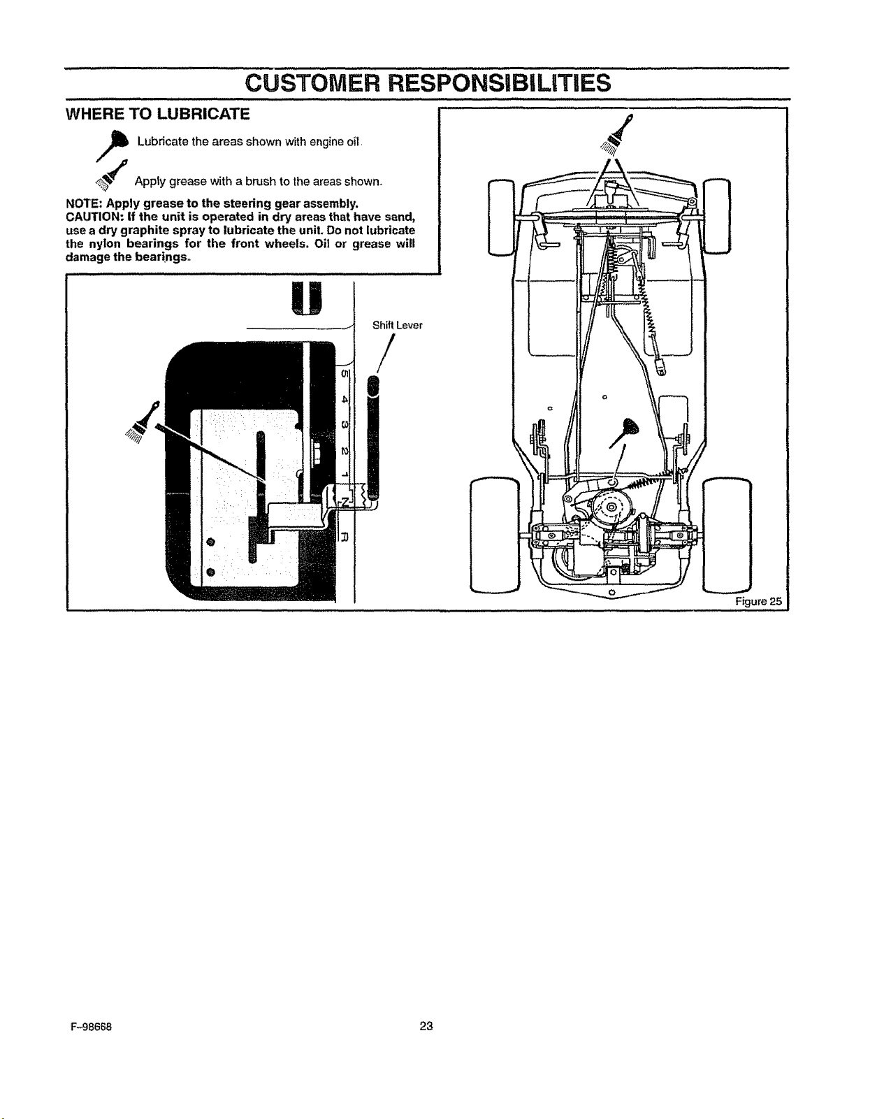
WHERE TO LUBRICATE
Lubricate the areas shown with engine oil,
,,_._ Apply grease with a brush to the areas shown,
NOTE: Apply grease to the steering gear assembly.
CAUTION: if the unit is operated in dry areas that have sand,
use a dry graphite spray to lubricate the unit. Do not lubricate
the nylon bearings for the front wheels. Oil or grease will
damage the bearings°
U
ShiftLever
/
Figure 25
F-98668 23
CUSTOMER RESPONSiBiLiTiES
ENGINE
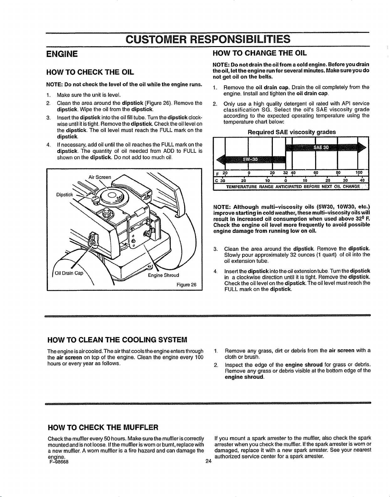
HOW TO CHECK THE OIL
NOTE: Do not check the level of the oil while the engine runs.
1,,
2..
Make sure the unitis level.
Clean the area around the dipstick (Figure 26),,Remove the
dipstick_ Wipe the oilfrom the dipstick..
3. Insertthe dipstick into the oi!filltube. Turnthe dipstick clock-
wise untilit istighLRemove the dipstick. Checktheoillevel on
the dipstick,. The oil level must reach the FULL mark on the
dipstick,
4,. Ifnecessary, add oil unti!the oilreaches the FULLmark onthe
dipstick. The quantity of oil needed from ADD to FULL is
shown onthe dipstick. Do not add too much oil
AirScreen
\
C_a'_p"_\ \\ Engine Shroud
Figure26
HOW TO CHANGE THE OIL
NOTE: Do not drain the oil from a cold engine. Before you drain
the oil, let the engine runfor several minutes. Make sure you do
not get oil on the beRs.
t,,
2o
Remove the oil drain cap, Drain the oil completely from the
engine. Install and tightenthe oil drain cap,
Only use a high quality detergent oil rated with API service
classification SG_ Select the oil's SAE viscosity grade
according to the expected operating temperature using the
temperature chart below:
Required SAE viscosity grades
........... i,,,
13EMPERATURE RANGE ANTICIPATED BEi_ORE NEXT O|L CHANGE, '.i
NOTE: Although multi-viscosity oils (5W30, 10W30, etc.)
improve starting in cold weather_these multi-viscosity oils will
result in increased oil consumption when used above 32o Fo
Check the engine oil level more frequently to avoid possible
engine damage from running low on oil.
3_
4,
Clean the area around the dipstick Remove the dipstick°
Slowly pour approximately 32 ounces(1 quart) of oil into the
oil extension tube.,
Insert the dipstick into theoilextension tube,"rumthe dipstick
in a clockwise direction untilit istight. Remove the dipstick.
Check the oillevel on the dipstick. The oillevel must reachthe
FULL mark on the dipstick.
HOW TO CLEAN THE COOLING SYSTEM
The engine is aircooted..The air thatcools the engine enters through
the air screen on top of the engine. Clean the engine every 100
hours orevery year as follows.
1, Remove any grass, dirt or debris from the air' screen with a
cloth or brush,
2,, Inspect the edge of the engine shroud for grass or debds,
Remove any grass or debris visibleat the bottomedge of the
engine shroud,,
HOW TO CHECK THE MUFFLER
Checkthe muffler every 50 hours. Make sure the muffler iscorrectly
mountedand isnot loose, If the muffler is wornorburnt, replacewith
a new muffler.A worn muffler is a fire hazard and can damage the
engine.
F-_98668 24
If yeu mount a spark arrester to the muffler, also check the spark
arrester when you check the muffler. Ifthe spark an'ester is worn or
damaged, replace it with a new spark arrester. See your nearest
authorized service center for a spark arrester_

...................................CUSTOMER RESPONSIBIL'ITIES .......................
HOW TO CLEAN THE AIR FILTERS
Some engines have two filters, an outerfoam fitter around an inner
paper filter,, Clean the air filters ever,/50 hours,,If you operate in
dirty conditions, service more often,,
NOTE: Never run the engine with the air fitters removed. The air
fitters wig help protect the engine against wear. For the correct
replacement filter, see the parts list for the engine.
1., Remove the two wingnuts from the cover (Figure 27).
2. Remove thecover from the air cleaner,,
3. Remove the two nuts from the filters_
4. Remove the air filters.
5. Clean the inside of the base and the cover with a cloth,
6o Remove thefoam fitter from the paper filter.
7. Ifequipped,wash thefoam filter in a detergent and watersolu-
tions,Toremove the water solution, tightlyrollthe foam filter in
adry cloth,,Remove the foam fitter from the cloth,,Completely
dry thefoam filter.
CAUTION; Do not wash the filters in gasoline or other
solvents that will burn.
8. Evenlyapply SAE 30W oil to the dry foam filter
9, To clean the paper filter, lightly tap the paper filter against a
hard fiat surface,,
10, If the paper filter is very dirty, replace the paper filter,
11,, Assembfe the air filters with the two nuts
12,, Install the cover,, Fasten the cover with the two wingnuts,,
Win(
Cover
Foam Filter'
Nul
Base
Figure 27
HOW TO CHECK THE SPARK PLUG
1 Check the gap of the spark plug with a feeler gauge
(Figure28), The correct gap is O_030'L
2, For easy starting and good performance, replace the spark
plug every two years,
Feeler Gauge
0,,030"
Figure 28
F-98668 25
SERVICE AND ADJUSTMENT
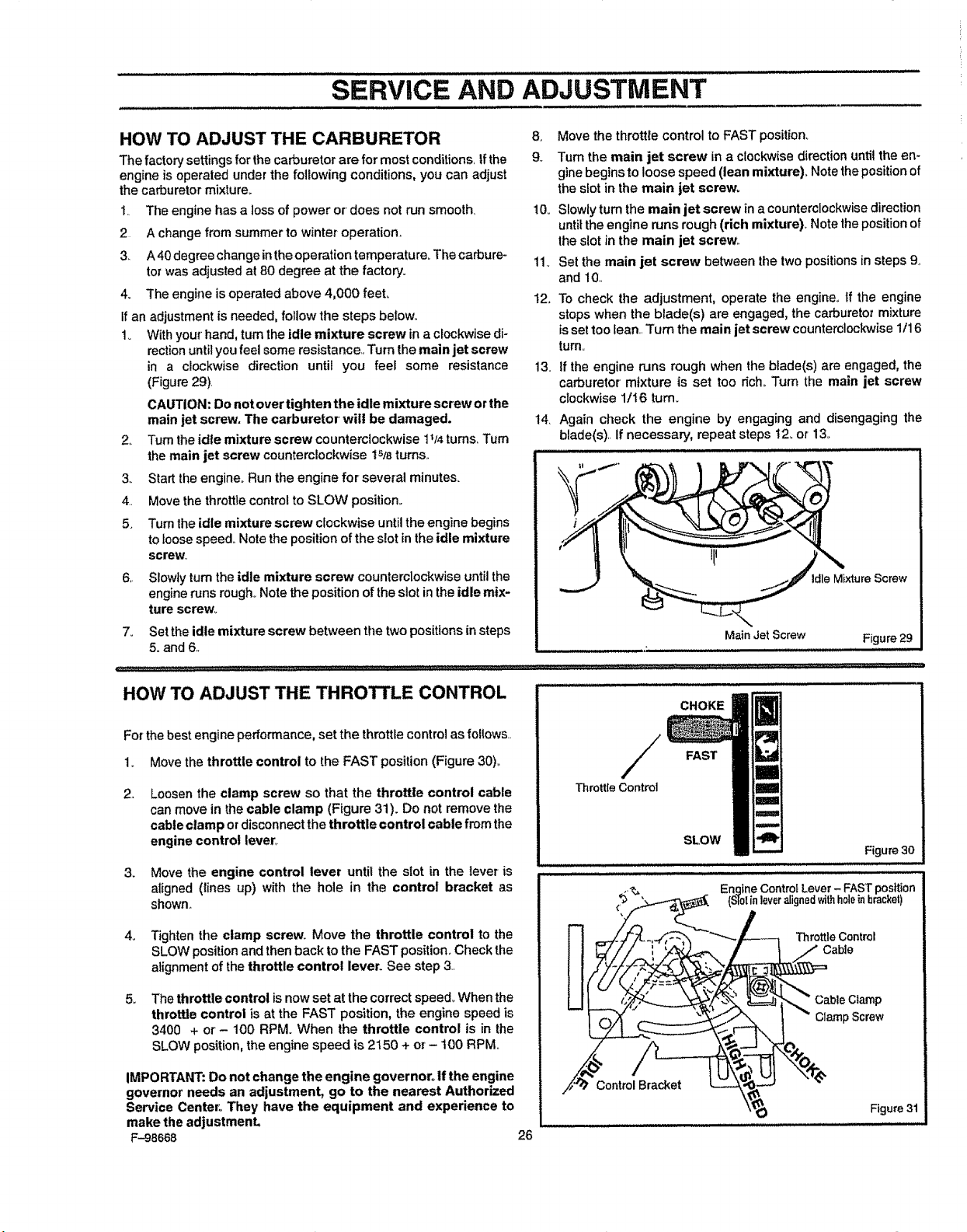
HOW TO ADJUST THE CARBURETOR
The factory settings for the carburetor are for most conditions_tfthe
engine isoperated underthe following conditions, you can adjust
the carburetor mixture+
1. The engine has a loss of power or does not run smooth+
2 A change from summer to winter operation.
3. A 40degree change inthe operation temperature+ The carbure-
tor was adjusted at 80 degree at the factory.
4. The engine is operated above 4,000 feel
Ifan adjustment is needed, follow the steps below+
1+ With your hand, turn the idle mixture screw in aclockwise di-
rection until you feel some resistance., Turn the main jet screw
in a clockwise direction until you feel some resistance
(Figure 29)
CAUTION: Do not over tighten the idle mixture screw or the
main jet screw. The carburetor" will be damaged.
2+ Turnthe idle mixture screw counterclockwise 1+/4tums_Turn
themain jet screw counterclockwise 15/Bturns+
3+ Start the engine+Run the engine for several minutes.
4+. Move the throttle control to SLOW position+
5+ Turn theidle mixture screw clockwise untilthe engine begins
to toose speed. Note the position of the slot inthe idle mixture
screw.,
6+ Slowly turn the idle mixture screw counterclockwise untilthe
engineruns rough,+Notethe position ofthe stotinthe idle mix-
ture screw+
7. Settheidle mixture screw between tlle twopositionsin steps
5. and 6+
11,,
!2.
8_ Move the throttle control to FAST position+
9,. Turn the main jet screw in a clockwise direction until the en-
ginebeginsto loose speed (lean mixture)+Note thepositionof
the slot in the main jet screw+
10+ Slowlyturn the main jet screw in a counterclockwisedirection
until the engine runs rough (rich mixture)+ Notethe positionof
the slot in the main jet screw,,
Set the main jet screw between the two positionsin steps 9,,
and 10..
13.
14+
To check the adjustment, operate the engine+ If the engine
stops when the blade(s) are engaged, the carburetor mixture
isset too lean..Turn the main jet screw counterclockwise 1tl 6
turn.,
if the engine runs rough when the blade(s) are engaged, the
carburetor mixture is set too dch+Turn the main jet screw
clockwise 1/16 tum+
Again check the engine by engaging and disengaging the
blade(s).. If necessary, repeat steps 12+or 13.
Mixture Screw
Main Jet Screw
Figure 29
HOW TO ADJUST THE THROTTLE CONTROL
For the best engine performance, set the throttle control as follows..
1+ Move the throttle control to the FAST position(Figure 30)+
2+
Loosen the clamp screw so that the throttle control cable
can move in the cable clamp (Figure 31). Do not remove the
cable clamp ordisconnectthe throttle control cable from the
engine control lever+
3. Move the engine control lever until the slot in the lever is
aIigned (lines up) with the hole in the control bracket as
shown+
4+ Tighten the clamp screw. Move the throttle control to the
SLOW positionand thenback to the FAST position.Check the
alignment of the throttle control lever. See step 3,
5_ The throttle control isnow set at the correctspeed+When the
throttle control is at the FAST position, the engine speed is
3400 + or- 100 RPM. When the throttle control is in the
SLOW position,the engine speed is 2150 + or- 100 RPM,,
IMPORTANT: Do not change the engine governor+ if the engine
governor needs an adjustment, go to the nearest Authorized
Service Center: They have the equipment and experience to
make the adjustmenL
F-98668 26
/
ThrottleControl
CHOKE
FAST
SLOW
Figure 30
Engine ControlLever - FAST position
{S10lin leveralignedwithh01einbracket)
Throttle Control
Cable
Cable Clamp
Clamp Screw
Control Bracket
Figure 31
SERVICE AND ADJUSTMENT
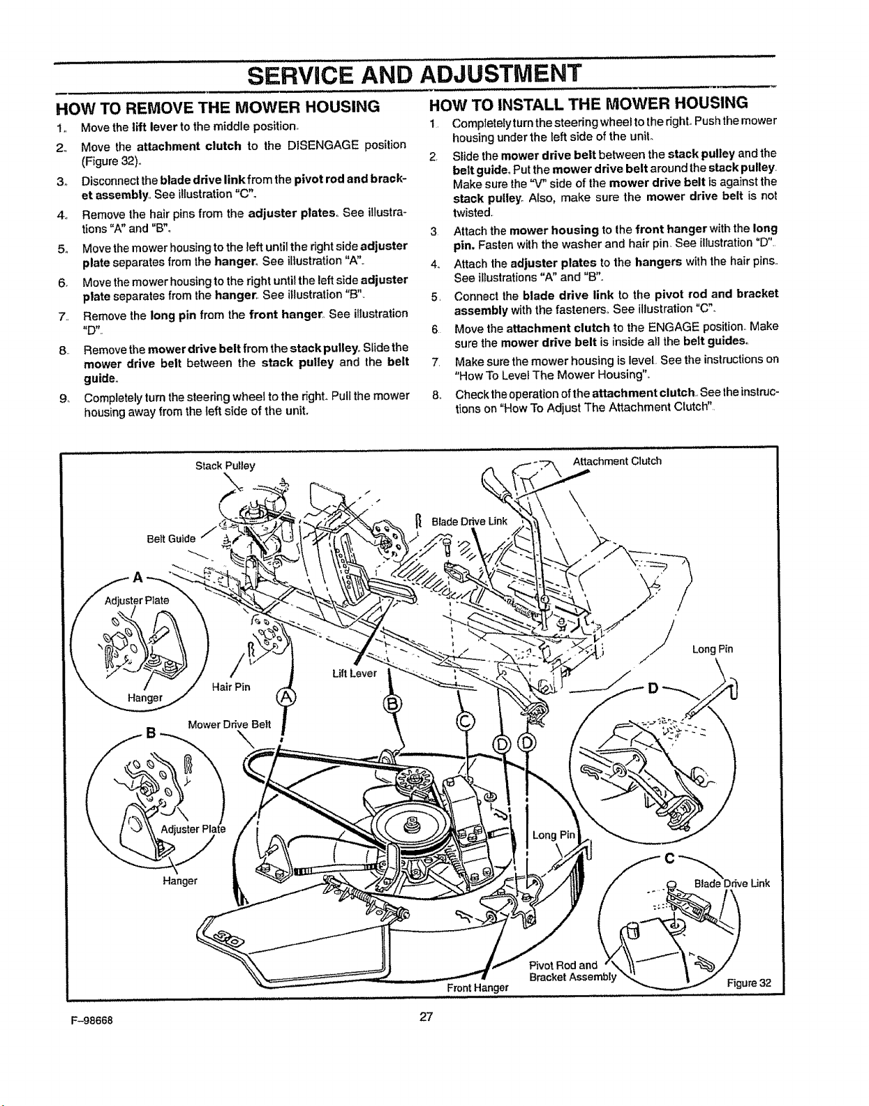
HOW TO REMOVE THE MOWER HOUSING
1,, Move the lift lever to the middle position°
2. Move the attachment clutch to the DISENGAGE position
(Figure 32),,
3o Disconnect the blade drive link from the pivot rod and brack-
et assembly., See illustration"C".
4o Remove the hair pins from the adjuster plates,, See illustra-
tions"A" and "B"o
5,, Move the mower housing to the left untilthe right side adjuster
plate separates from the hanger° See illustration"A".
6. Move the mower housing to the right until the left side adjuster
plate separates from the hanger,, See illustration "t3".
7., Remove the long pin from the front hanger. See illustration
8. Remove the mower drive belt from the stack pulley,.Slidethe
mower drive belt between the stack pulley and the belt
guide,,
9o Completelyturnthesteering wheel to the right.Pullthe mower
housing away from the left side of the unit.
HOW TO INSTALL THE MOWER HOUSING
1, Completelyturnthesteering wheel to the dghtoPushthemower
housing under the left side ofthe uniL
2, Slide the mower drive belt between the stack pulley andthe
belt guide. Putthe mower drive belt around the stack pulley.
Make sure the"V" side of the mower drive belt isagainst the
stack pulley° Also, make sure the mower drive belt is not
twisted.
3 Attach the mower housing to the front hanger with the long
pin. Fastenwith the washer and hair pin. See illustration "D",,
4o Attach the adjuster plates to the hangers with the hair pins.,
See illustrations "A" and "B'L
5, Connect lhe blade drive link to the pivot rod and bracket
assembly withthe fasteners,, See illustration"C"_
6 Move theattachment clutch to the ENGAGE position., Make
sure the mower drive belt is inside all the belt guides°
7. Make sure the mower housing is level See the instructions on
"How To LevelThe Mower Housing",.
8o Checktheoperationofthe attachment clutch., See theinstruc-
tionson"How To Adjust The Attachment Clutch"
AttachmentClutch
Hanger
HairPin
MowerDriveBelt
-..
UftLever
Blade Drive Link
Hanger
Blade Ddve Link
Pivot Rodand
BracketAssembly
FrontHanger
Figure 32
F-98668 27
SERVICE AND ADJUSTMENT
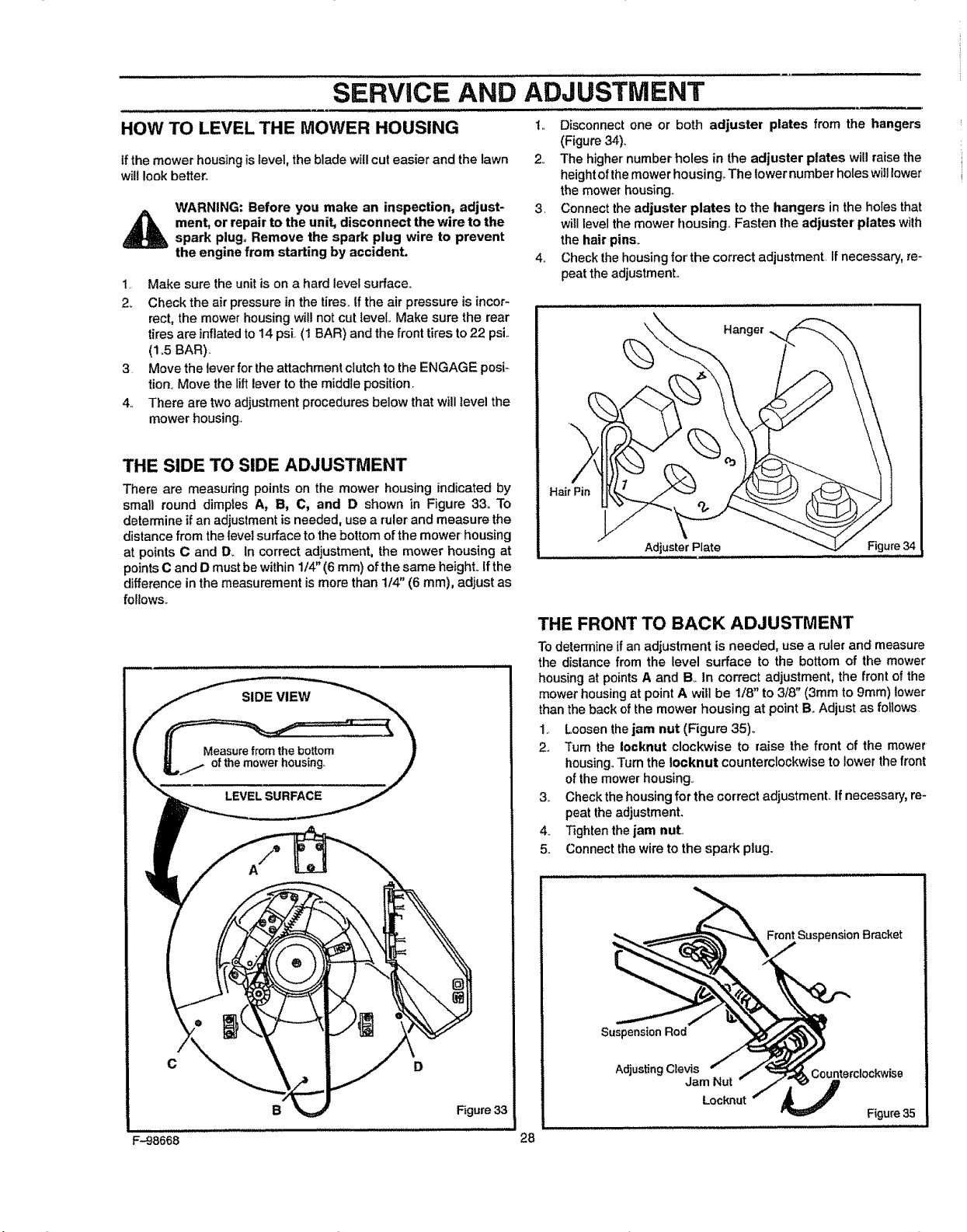
HOW TO LEVEL THE MOWER HOUSING t,. Disconnect one or both adjuster plates from the hangers
(Figure 34).
if the mower housing islevel, the blade will cut easier and the lawn
will look better°
WARNING: Before you make an inspection, adjust-
_ ment, or repair to the unit, disconnect the wire to the
spark plug+ Remove the spark plug wire to prevent
the engine from starting by accident.
1. Make sure the unitis on a hard level surface..
2+ Check the air pressure in the tires, tf the air pressure is incor-
rect, the mower housing willnot cut level.. Make sure the rear
tires are inflatedto 14 psi (1 BAR) and the front tires to 22 psi..
(1+5BAR).
3. Move the leverfor the attachment clutchto the ENGAGE posi+
lion+ Move the lift lever tothe middle position.
4.. There are two adjustment procedures below that willlevel the
mower housing..
2.. The higher' number holes in the adjuster plates will raisethe
height of the mower housing,. The lowernumberholes will lower
the mower housing+
3. Connect the adjuster plates to the hangers in the holes that
will level the mower housing. Fasten the adjuster' plates wilh
the hair pins.
4+ Check the housing for'the correct adjustment. If necessary, re-
peat the adjustmenL
THE SIDE TO SIDE ADJUSTMENT
There are measuring points on the mower housing indicated by
small round dimples A, B, C, and D shown in Figure 33. To
determine if an adjustment is needed, use a ruler and measure the
distance from the level surface to the bottom of the mower' housing
at points C and D+ In correct adjustment, the mower housing at
points C and D must be within 1/4' (6 ram) of the same height, tfthe
difference in the measurement is more than 1/4" (6 mm), adjust as
follows.+
C D
B Figure 33
Hanger
Hal
Adjuster Plate Figure 34
THE FRONT TO BACK ADJUSTMENT
To determineif an adjustment isneeded, use a ruler and measure
the dislance from the level surface to the bottom of the mower
housingat pointsA and B,+in correct adjustment, the front ofthe
mowerhousingat pointA will be 1/8" to 3/8" (3mm to 9mm) lower
than theback ofthe mower housing at point B. Adjust as follows.
1.. Loosenthejam nut (Figure 35)+
2, +rum the Iocknut clockwise to raise the front of the mower
housing.,+rumthe !ocknut counterclockwise tolower the front
ofthe mower housing.,
3., Check thehousingfor the correct adjustment,. Ifnecessary,re-
peat the adjustment.
4+ Tightenthe jam nut,,
5. Connect the wire tothe spark plug.
Suspension Bracket
Suspension Rod
Adjusting Clevis Counterclockwise
Jam Nut
Locknut
Figure 35
F-98668 28
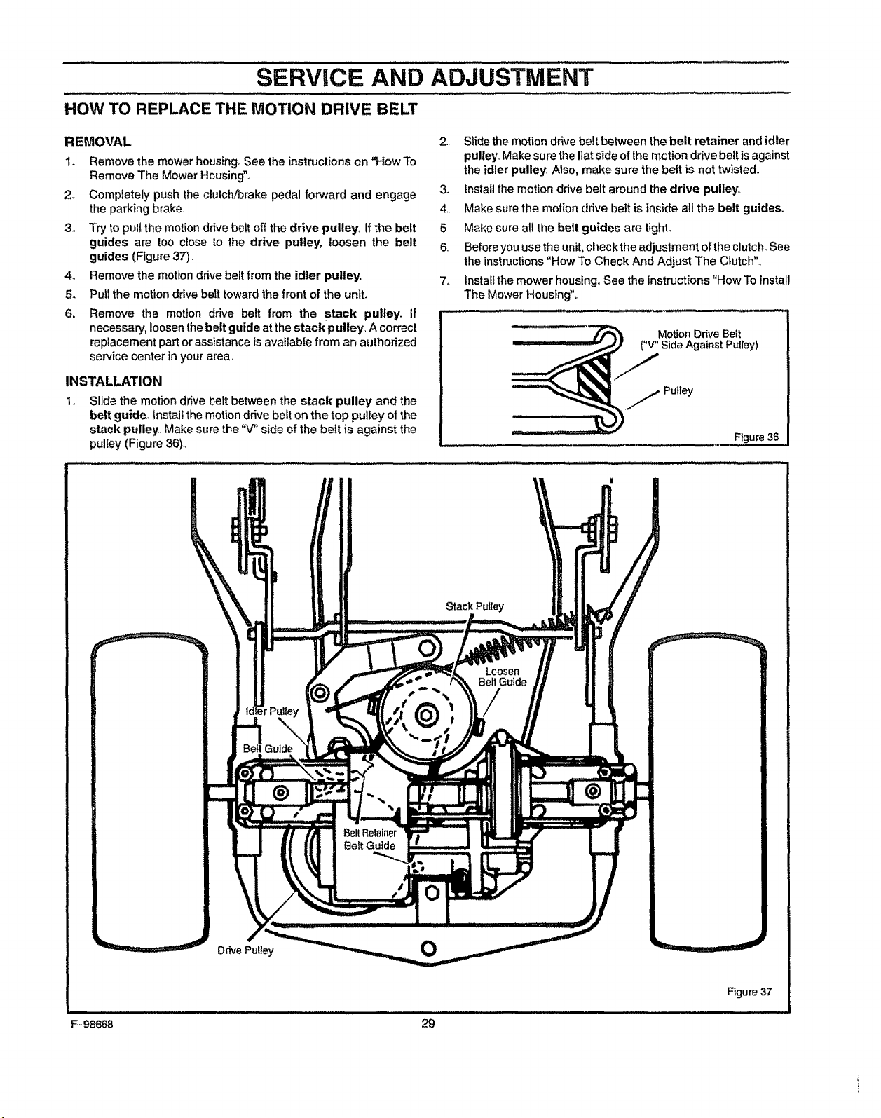
sERvicE AND ADJUSTMENT
HOW TO REPLACE THE MOTION DRIVE BELT
REMOVAL
4,,
5.
6.
1. Remove the mower housing.See the instructions on "How To
Remove The Mower Housing"°
2., Completely push the clutch/brake pedal forward and engage
the parking brake,,
3o Try to pull the motion drive belt off the drive pulley,, ffthe belt
guides are too close to the drive pulley, loosen the belt
guides (Figure 37),
Remove the motion drive belt from the idler pulley,,
Putl the motion drive belt toward the front of the unit.
Remove the motion drive belt from the stack pulley. If
necessary, loosen thebelt guide atthe stack pulley, A correct
replacement part or assistance is available from an authorized
service center in your area,
INSTALLATION
Slide the motiondrivebest between the stack pulley and the
belt guider install the motion drive belt on the top pulley of the
stack pulley. Make sure the "V" side of the belt is against the
pulley(Figure 36).,
2, Slide the motion drive belt between the belt retainer and idler
pulley° Makesure theflat side of the motion drive belt isagainst
the idler pulley Also, make sure the belt is not twisted.
3. Instal]the motion drive belt around the drive pulley.,
4,, Make sure the motion drive belt is inside all the belt guides.
5. Make sure all the belt guides are tight,,
6, Beforeyou use theunit, check the adjuslment of the clutch,,See
the instructions "How To Check And Adjust The Clutch".
7_ tnsta[Ithe mower housing. See the instructions"How To Install
The Mower Housing",,
Motion Drive Belt
Side Against Pulley)
) j Putley
Figure 36
Stack Pulley
BellRelainer
Belt Guide
Drive Pulley
0
Figure 37
F-98668 29
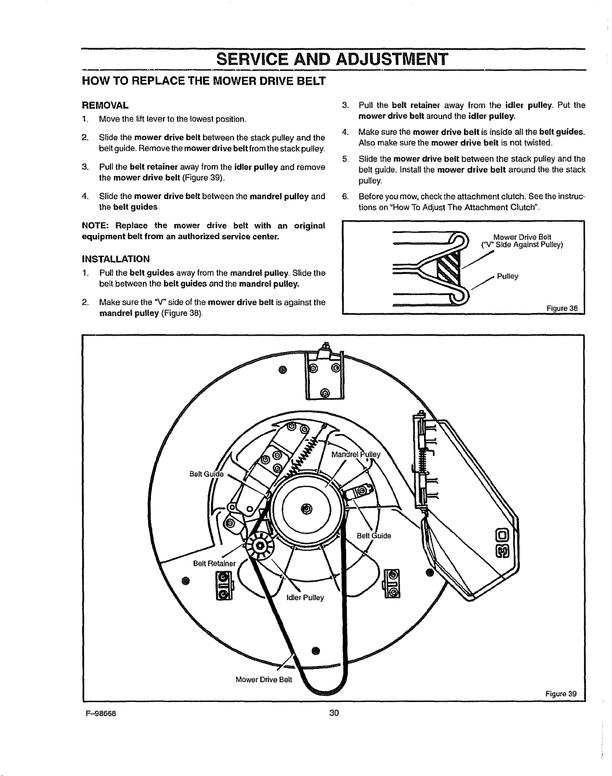
SERVICE AND ADJUSTMENT
HOW TO REPLACE THE MOWER DRIVE BELT
REMOVAL 3.
1. Move the liftlever tothe lowest position._
4.
2. Slide the mower drive belt between the stack pulley and the
belt guide_ Remove the mower drive belt from the stack pulley.
5,
3. Pull the belt retainer away from the idler' pulley and remove
the mower drive belt (Figure 39)..
4_ Slide the mower drive belt between the mandrel pulley and 6.
the belt guides.
originalNOTE: Replace the mower drive belt with an
equipment belt from an authorized service center.
INSTALLATION
1_ Pull the belt guides away from the mandrel pulley Slide the
belt between the belt guides and the mandrel pulley,
2. Make sure the _ side of the mower drive belt is against the
mandrel pulley (Figure38)..
Pull the belt retainer away from the idler pulley,. Put the
mower drive belt around the idler' pulley_
Make sure the mower"drive belt is inside all the belt guides,
Also makesure the mower drive belt is not twisted,
Slide the mower drive belt between the stack pulley and the
belt guide. Install the mower drive belt around the the stack
pulley°
Before you mow, check the attachment clutch° See theinstruc-
tions on "How To Adjust The Attachment Clutch'L
)_ Mower DriveBell
SideAgainstPulley)
)_)j Pu|ley
Figure38
I.HH ... ....
F-98668
®
Mower Drive Belt
Id)er Pulley
®
@
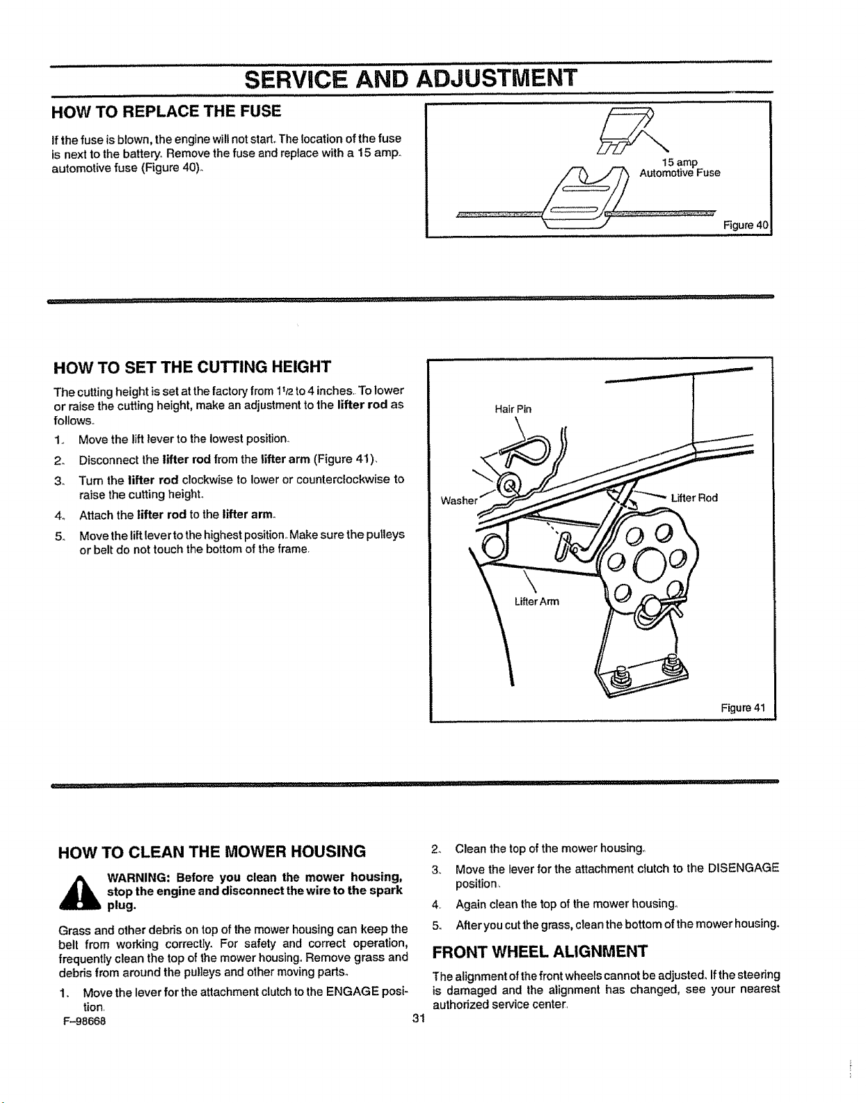
SERVICE AND ADJUSTMENT
HOW TO REPLACE THE FUSE
Ifthe fuse isblown, the engine will not start The tocation of the fuse
is next to the battery. Remove the fuse and replace with a 15 amp
automotive fuse (Figure 40)
15 amp
AutomotiveFuse
Figure4(;
HOW TO SET THE CUTTING HEIGHT
The cuttingheight isset atthe factory from 1t/2to4 inches..Tolower
or raise the cuttingheight, make an adjustment tothe lifter rod as
follows.
1+, Move the liftlever to the lowest position.
2o Disconnect the lifter rod from the lifter arm (Figure 41).
3. Turn the lifter rod clockwiseto lower or counterclockwise to
raise the cuttingheighL
4° Attach the lifter rod tothe lifter arm.
5. Movethe lift leverto thehighestposition..Makesure the pulleys
or belt do not touchthe bottomofthe frame,
Hair Pin
Lifter Rod
Figure 41
HOW TO CLEAN THE MOWER HOUSING
,_ WARNING: Before you clean the mower housing,
stop the engine and disconnect the wire to the spark
plug.
Grass and other debris ontop of the mower housing can keep the
belt from working correctly. For safety and correct operation,
frequently clean the top of the mower housing° Remove grass and
debris from around the pulleys and other moving parts°
1+ Move the lever for the attachment clutch to the ENGAGE posi-
tion
F-98668
3t
2 Clean the top ofthe mower housing1
3+ Move the lever for the attachment clutch to the DISENGAGE
position
4 Again clean the top of the mower housing
5 After you cut thegrass, clean the bottom of the mower housing
FRONT WHEEL ALIGNMENT
The alignment of the front wheels cannot be adjusted° Ifthe steering
is damaged and the alignment has changed, see your nearest
authorized service center
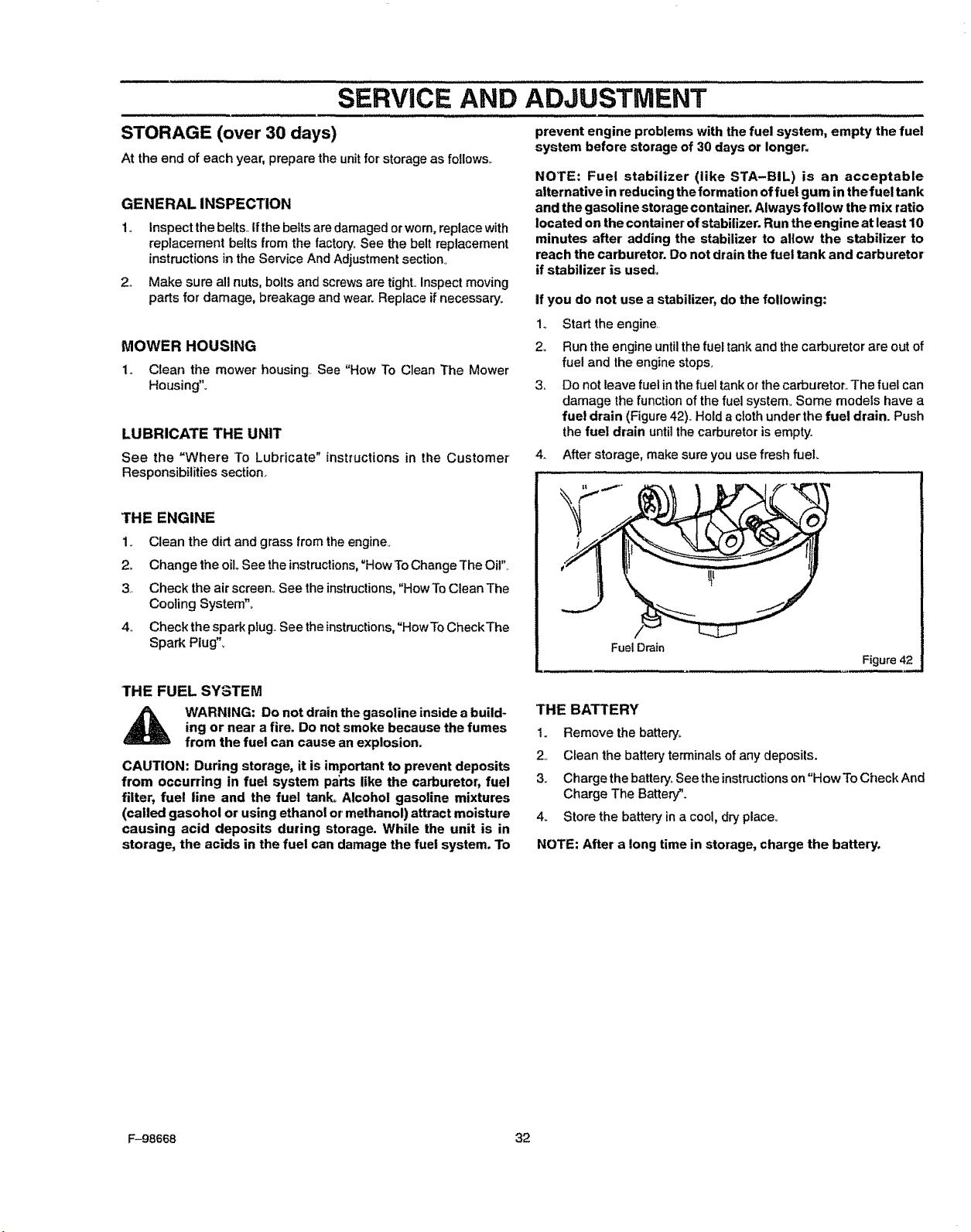
SERVICE AND ADJUSTMENT
STORAGE (over 30 days)
At the end of each year, prepare the unitforstorageas follows,.
GENERALINSPECTION
2,,
Inspect the belts.,tf the belts are damaged or worn, replace with
replacement belts from the factory, See the belt replacement
instructions inthe Service And Adjustment section°
Make sure all nuts, bolts and screws are tight..Inspect moving
parts for damage, breakage and wear. Replace if necessary.
MOWER HOUSING
1, Clean the mower housing See "How To Clean The Mower
Housing'L
LUBRICATE THE UNIT
See the "Where To Lubricate" instructions in the Customer'
Responsibilities section..
THE ENGINE
1_ Clean the dirt and grass from the engine._
2, Change the oil See the instructions,"How To Change The Oil",
3. Check the air screen., See the instructions, "How To Clean The
Cooling System",
4., Check the spark piug.,See the instructions, "How To CheckThe
Spark Plug"..
prevent engine problems with the fuel system, empty the fuel
system before storage of 30 days or longer.
NOTE: Fuel stabilizer (like STA-BIL) is an acceptable
alternative in reducing the formation offuel gum inthe fuel tank
and the gasoline storage container. Always follow the mix ratio
located on the container of stabilizer. Run the engine at least 10
minutes after adding the stabilizer to allow the stabilizer to
reach the carburetor. Do not drain the fuel tank and carburetor
if stabilizer is used.
if you do not use a stabilizer, do the following:
1. Start the engine
2o Run the engine untilthe fuel tankand thecarburetor are outof
fuel and the engine stops,
3_ Do not leave fuel in the fuel tank or the carburetor.. The fuel can
damage the function of the fuel system° Some models have a
fuel drain (Figure 42)_Hold acloth under the fuel drain. Push
the fuel drain until thecarburetor is empty.
4. After storage, make sure you use fresh fuel.
Fuel Drain
Figure 42
THE FUEL SYSTEM
WARNING: Do not drainthe gasoline inside a build-
ing or near a fire. Do not smoke because the fumes
from the fuel can cause an explosion.
CAUTION: During storage, it is important to prevent deposits
from occurring in fuel system parts like the carburetor, fuel
filter, fue! line and the fuel tanks Alcohol gasoline mixtures
(called gasohol or using ethanol or'methanol) attract moisture
causing acid deposits during storage. While the unit is in
storage, the acids in the fuel can damage the fuel system. To
THE BATTERY
Io Remove the batter't_
2o Clean the battery terminals of any deposits.
3_ Charge the battery_See the instructions on"Hew To Check And
Charge The Battery".
4_ Store the battery in a cool, dry place,,
NOTE: After a long time in storage, charge the battery.
F-98668 32
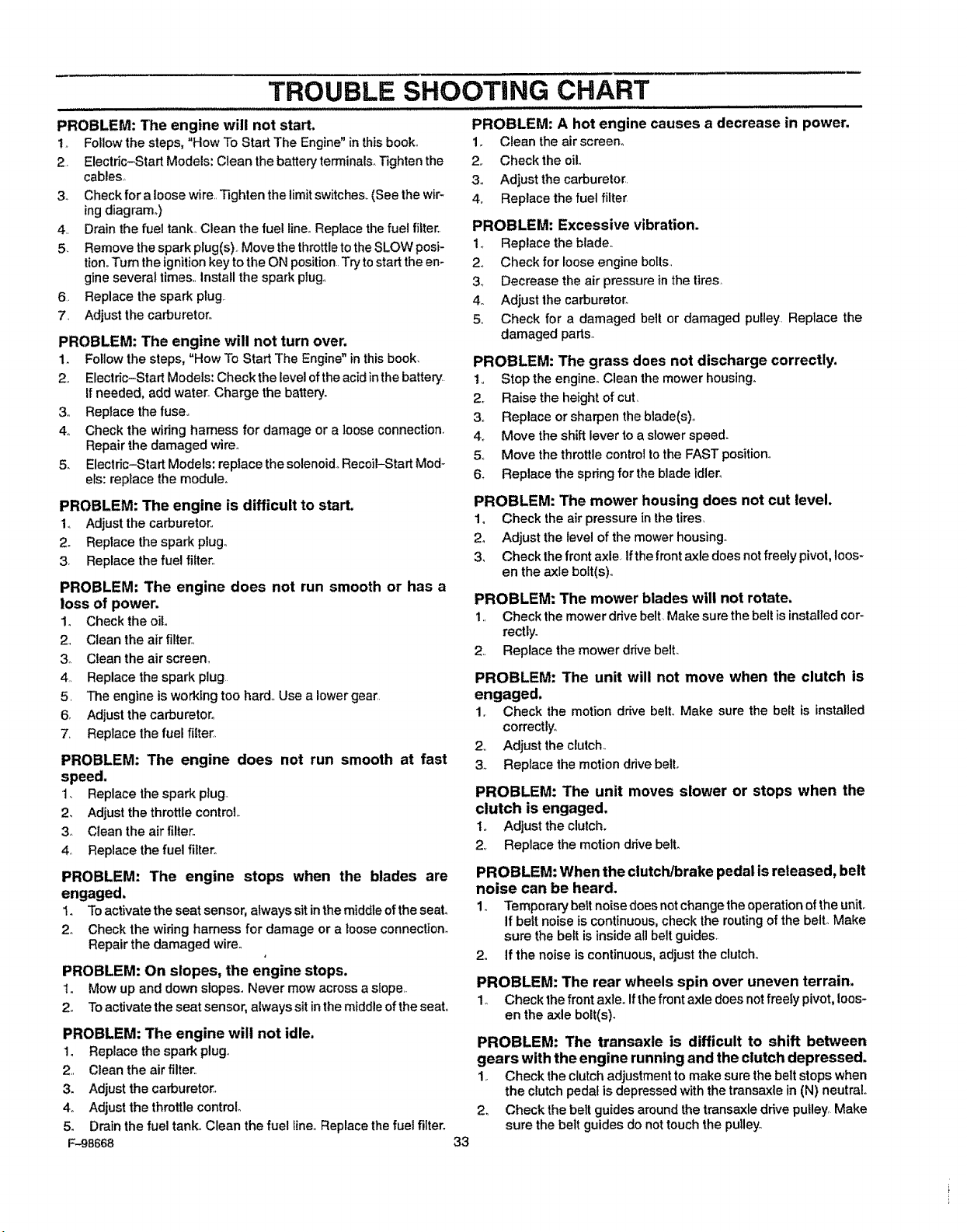
TROUBLE SHOOTING CHART
PROBLEM: The engine will not start.
to Followthe steps, "How To Start The Engine" in this book.
2 Electric-Start Models: Clean the battery terrninals.Tightenthe
cables,,
3o Check for a loose wire Tighten the limit switches. (See the wir-
ingdiagram..)
4 Drain the fuel tank.,Clean the fuel linerReplacethe fuel filter,
5. Remove the spark plug(s), Move thethrottletotheSLOW posi-
tion,,Turn the ignitionkey to the ON positionTrytostart theen-
gineseveral times., installthe spark plug_
6 Replace the spark plug
7 Adjust the carburetor,,
PROBLEM: The engine will not turn over.
1. Follow the steps, "How To Start The Engine" in thisbook,
2, Electric-Start Models:Check the levelof theacidin thebattery
Ifneeded, add water°Charge the battery.
3,, Replace the fuse.,
4o Check the wiring harness for damage or a loose connection,
Repair the damaged wire°
5_ Electric-Start Models: replace the solenoid.Recoil-Start Mod-
els: replace the module.
PROBLEM: The engine is difficult to start.
1. Adjust the carburetor,,
2o Replace the spark plug.
3, Replace the fue! filter.,
PROBLEM: The engine does not run smooth or has a
loss of power.
1o Check the oil,,
2, Clean the airfilter,,
3o Clean the air screem
4, Replace the spark plug
5, The engine is working too hard. Use a lower gear,
6, Adjust the carburetor.
7, Replace the fuel filter.
PROBLEM: The engine does not run smooth at fast
speed.
1, Replace the spark plug.
2. Adjust the throttle control
3o Clean the air filter,,
4_ Replace the fuel filter,,
PROBLEM: The engine stops when the blades are
engaged.
I. Toactivatethe seat sensor,always sitinthe middle ofthe seal
2o Check the wiring harness for damage or a looseconnection_
Repair the damaged wire°
PROBLEM: On slopes, the engine stops.
1_ Mow up and down slopes,, Never mow across a slope,
2., To activatethe seat sensor, always sit in the middle ofthe seat,,
PROBLEM: The engine will not idle.
1. Replace the spark plug.
2, Clean the air filter,
3. Adjust the carburetor*,
4.. Adjust the throttle control°
5. Drain the fuel tank. Clean the fuel line,,Replace thefuel filter.
F.-98668
PROBLEM: A hot engine causes a decrease in power.
1. Clean the airscreen.
2, Check the oil,,
3, Adjust the carburetor
4. Replace the fuel filter,
PROBLEM: Excessive vibration.
1., Replace the blade,,
2, Check for loose engine bolts,
3_ Decrease the air pressure in the tires,
4. Adjust the carburetor_
5, Check for a damaged belt or damaged pulley Replace the
damaged parts,,
PROBLEM: The grass does not discharge correctly.
1,, Stop the engine_ Clean the mower housing.
2., Raise the height of cut,
3., Replace or sharpen the blade(s)_,
4., Move the shift lever to a slower speed.
5, Move the throttle control to the FAST position,,
6_ Replace the spring for the blade tdler_
PROBLEM: The mower housing does not cut level.
1o Check the air pressure in the tires,
2o Adjust the level ofthe mower housing_
3_ Checkthe front axle, Ifthefront axledoes not freely pivot,loos-
en the axle bolt(s).,
PROBLEM: The mower blades will not rotate.
1., Check the mower drive belt Make sure the belt is installedcor-
rectly.
2., Replace the mower drive bell
PROBLEM: The unit will not move when the clutch is
engaged.
1, Check the motion drive bell Make sure the belt is installed
correctly°
2, Adjust the clutch.
3o Replace the motion drive belt.
PROBLEM: The unit moves slower or stops when the
clutch is engaged,
Io Adjustthe clutch.
2, Replacethe motiondrivebell
PROBLEM: When the clutch/brake pedal is released, belt
noise can be heard.
1_ Temporary' belt noise does not change theoperation of theunit,
If belt noise is continuous, check the routingof the bell Make
sure the belt is inside all belt guides,
2,, if the noise is continuous, adjust the clutch_
PROBLEM: The rear wheels spin over uneven terrain,
1o Check the front axle. Ifthefront axle does not freely pivot, loos-
en the axle bolt(s)_
PROBLEM: The transaxle is difficult to shift between
gears with the engine running and the clutch depressed.
1_ Check the clutchadjustment to make sure the belt stops when
the clutch pedal is depressed with the transaxle in (N) neutral°
2_ Check the belt guides around the transaxle drive pulley, Make
sure the belt guides do not touch the pulley.
33
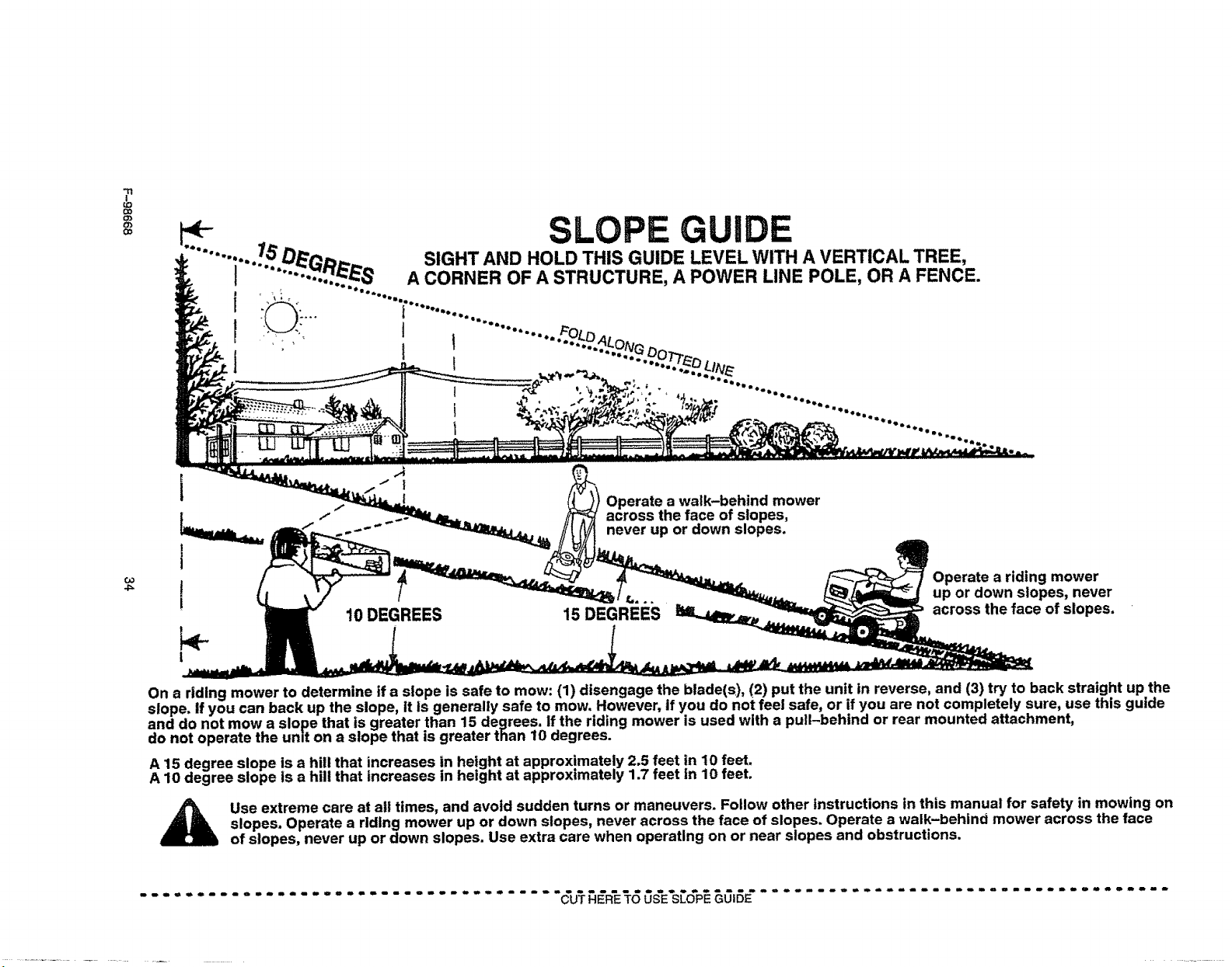
?
LO
0:,
(33
4_
i
t
!
Operate a walk-behind mower
across the face of slopes,
never up or down slopes.
{t= _.
10 DEGREES 15 DEGREES
Operate a riding mower
up or down slopes, never
across the face of slopes.
On a riding mower to determine if a slope is safe to mow: (1) disengage the blade(s), (2) put the unit in reverse, and (3) try to back straight up the
slope. If you can back up the slope, It Is generally safe to mow. However, if you do not feel safe, or if you are not completely sure, use this guide
and do not mow a slope that is greater than 15 degrees. If the riding mower is used with a pull-behind or rear mounted attachment,
do not operate the unit on a slope that is greater than 10 degrees.
A 15 degree slope is a hill that increases in height at approximately 2.5 feet in 10 feet.
A 10 degree slope is a hill that increases in height at approximately 1.7 feet in 10 feet.
Use extreme care at atl times, and avoid sudden turns or maneuvers. Follow other instructions in this manual for safety in mowing on
slopes. Operate a riding mower up or down slopes, never across the face of slopes. Operate a walk-behind mower across the face
of slopes, never up or down slopes. Use extra care when operating on or near slopes and obstructions.
CUT R'E S'E'S ........................
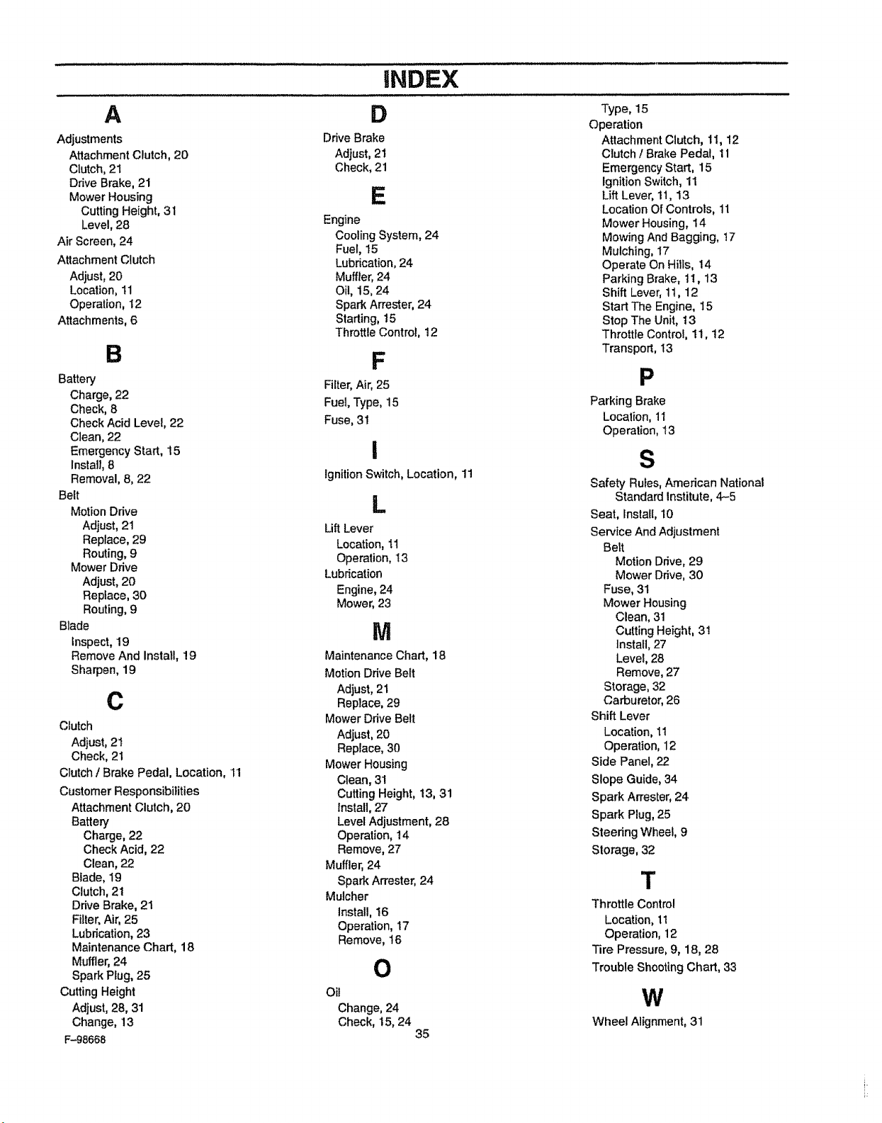
A
Adjustments
Attachment Clutch, 20
Clutch, 21
Drive Brake, 21
Mower Housing
Cutting Height, 31
Level, 28
Air Screen, 24
Attachment Clutch
Adjust, 20
Location, 11
Operation, 12
Attachments, 6
B
Battery
Charge, 22
Check, 8
Check Acid Level, 22
Clean, 22
Emergency Start, 15
Install, 8
Removal, 8, 22
Belt
Motion DAve
Adjust, 21
Replace, 29
Routing, 9
Mower DAve
Adjust, 20
Replace, 30
Routing, 9
Blade
Inspect, 19
Remove And Install, 19
Sharpen, 19
C
Clutch
Adjust, 21
Check, 21
Clutch / Brake Pedal, Location, 11
Customer Responsibilities
Attachment Clutch, 20
Battery
Charge, 22
Check Acid, 22
Clean, 22
Blade, 19
Clutch, 21
DAveBrake, 21
Filter, Air, 25
Lubrication, 23
Maintenance Chart, 18
Muffler, 24
Spark Plug, 25
Cutting Height
Adjust, 28, 31
Change, 13
F-98668
iNDEX
D
DAveBrake
Adjust, 21
Check, 21
E
Engine
Cooling System, 24
Fuel, t5
Lubrication, 24
Muffler, 24
Oil, 15, 24
Spark Arrester, 24
Starting, 15
Throttle Control, 12
F
Filter, Air, 25
Fuel, Type, 15
Fuse, 31
i
ignition Switch, Location, 11
L
Lift Lever
Location, 1t
Operation, 13
Lubrication
Engine, 24
Mower, 23
M
Maintenance Chart, 18
Motion Drive Belt
Adjust, 21
Reptace, 29
Mower Drive Belt
Adjust, 20
Replace, 30
Mower Housing
Clean, 31
Cutting Height, t3, 31
Install, 27
Level Adjustment, 28
Operation, 14
Remove, 27
Muffler, 24
Spark Arrester, 24
Mulcher
Install, 16
Operation, 17
Remove, t6
O
Oil
Change, 24
Check, 15, 24
35
Type, 15
Operation
Attachment Clutch, 1I, 12
Clutch / Brake Pedal, 11
Emergency Start, 15
Ignition Switch, 11
Lift Lever, 11, 13
Location OfControls, tl
Mower Housing, 14
Mowing And Bagging, 17
Mulching, 17
Operate On Hills, 14
Parking Brake, 11, 13
Shift Lever, 11, 12
Start The Engine, 15
Stop The Unit, 13
Throttle Control, 11, !2
Transport, 13
P
Parking Brake
Location, 11
Operation, 13
S
Safety Rules,American National
Standard Institute, 4-5
Seat, Install, 10
Service And Adjustment
Belt
Motion DAve, 29
Mower Drive, 30
Fuse, 31
Mower Housing
Clean, 31
Cutting Height, 31
Install, 27
Level, 28
Remove, 27
Storage, 32
Carburetor, 26
Shift Lever
Location,11
Operation, 12
Side Panel, 22
Slope Guide, 34
Spark Arrester, 24
Spark Plug, 25
Steering Wheel, 9
Storage, 32
T
Throttle Control
Location, 11
Operation, 12
Tire Pressure, 9, 18, 28
Trouble Shooting Chart, 33
W
Wheel Alignment, 31
owner's
Model No.
502.270210
To Call Toll Free
For Service
1--800-4-REPAIR
(1-800-473-7247)
For Parts
1-800-366-PART
(1-800-366-7278)
CRRFTSMRN
13.5
30" MOWER
5
EAR
The Model Number for the mower is found on a decal attached tothe back of
the frame.,The Model Number' for the engine is found on the blower housing
above thespark plug. Always give the Model Number when you call forservice
or order repair parts for your' unit.
Repair parts can be ordered from any Sears Service Center/Department and
most Sears Stores_
WHEN ORDERING REPAIR PARTS, ALWAYS HAVE THE FOLLOWING
INFORMATION AS SHOWN IN THIS LIST.
• PRODUCT- REAR ENGINE RIDER
e MODEL NUMBER - 502.270210
• ENGINE MODEL NO. 143981300
o PART NUMBER
e PART DESCRIPTION
Your Sears merchandise has added value when you consider Sears has service units
nationwide staffed with Sears trained technicians. Sears technicianshave the necessary
parts, toots and equipment tomeet the Sears pledge, '_WeService What We Sell".
F-98668 Sears, Roebuck and Co., Hoffman Estates, |L. 60179 U.S.A. PrintedinUS_A.