

WARNING
Before using this equipment, read the manual and follow all safety rules and operating instructions. SAVE THESE INSTRUCTIONS!
CRAFTSMAN® is a registered trademark of Stanley Black & Decker, Inc., used under license.
CRAFTSMAN® es una marca registrada de Stanley Black & Decker, Inc., utilizada bajo licencia.
© 2018 CRAFTSMAN U.S. & Canada Only
CRAFTSMAN.com
Form No. 769-16521B
(January 21, 2019)
INSTRUCTION MANUAL | MANUAL DE INSTRUCTIONES
T200 & T300 SERIES
LAWN TRACTOR/TRACTORES CORTACÉSPED
Model Nos. CMXGRAM1130043; CMXGRAM1130044; CMXGRAM1130045;
CMXGRAM1130047 & CMXGRAM7821291
IF YOU HAVE QUESTIONS OR COMMENTS, CONTACT US.
SI TIENE DUDAS O COMENTARIOS, CONTÁCTENOS.
1-888-331-4569 WWW.CRAFTSMAN.COM
NOTE: This Operator’s Manual covers several models. Features may vary by model. Not all features in this manual are applicable to all models and the model depicted may differ
from yours.

2
SAFETY INSTRUCTIONS
GENERAL OPERATION
• Read, understand, and follow all instructions on the machine and in the
manual(s) before attempting to assemble and operate. Keep this manual in
a safe place for future and regular reference and for ordering replacement
parts.
• Be familiar with all controls and their proper operation. Know how to stop
the machine and disengage them quickly.
• Never allow children under 14 years old to operate this machine. Children 14
years old and over should read and understand the operation instructions
and safety rules in this manual and should be trained and supervised by a
parent.
• Never allow adults to operate this machine without proper instruction.
• To help avoid blade contact or a thrown object injury, keep bystanders,
helpers, children and pets at least 75 feet from the machine while it is in
operation. Stop machine if anyone enters the area.
• Thoroughly inspect the area where the equipment is to be used. Remove
all stones, sticks, wire, bones, toys, and other foreign objects which could
be picked up and thrown by the blade(s). Thrown objects can cause serious
personal injury.
• Plan your mowing pattern to avoid discharge of material toward roads,
sidewalks, bystanders and the like. Also, avoid discharging material against
a wall or obstruction which may cause discharged material to ricochet back
toward the operator.
• Always wear safety glasses or safety goggles during operation and while
performing an adjustment or repair to protect your eyes. Thrown objects
which ricochet can cause serious injury to the eyes.
• Wear sturdy, rough-soled work shoes and close-fitting slacks and shirts.
Loose fitting clothes and jewelry can be caught in movable parts. Never
operate this machine in bare feet or sandals.
• For extended use of this product, hearing protection is required.
• Be aware of the mower and attachment discharge direction and do not point
it at anyone. Do not operate the mower without the discharge cover or entire
grass catcher in its proper place.
• Do not put hands or feet near rotating parts or under the cutting deck.
Contact with the blade(s) can amputate hands and feet.
• A missing or damaged discharge cover can cause blade contact or thrown
object injuries.
• Stop the blade(s) when crossing gravel drives, walks, or roads and while not
cutting grass.
• Watch for traffic when operating near or crossing roadways. This machine is
not intended for use on any public roadway.
• Do not operate the machine while under the influence of alcohol or drugs.
• Mow only in daylight or good artificial light.
• Never carry passengers.
• Disengage blade(s) before shifting into reverse. Back up slowly. Always look
down and behind before and while backing to avoid a back-over accident.
• Slow down before turning. Operate the machine smoothly. Avoid erratic
operation and excessive speed.
• Disengage blade(s), set parking brake, stop engine and wait until the
blade(s) come to a complete stop before removing grass catcher, emptying
grass, unclogging chute, removing any grass or debris, or making any
adjustments.
• Never leave a running machine unattended. Always turn off blade(s), set
parking brake, stop engine and remove key before dismounting.
• Use extra care when loading or unloading the machine into a trailer or truck.
This machine should not be driven up or down ramp(s), because the machine
could tip over, causing serious personal injury. The machine must be pushed
manually on ramp(s) to load or unload properly.
• Muffler and engine become hot and can cause a burn. Do not touch.
WARNING
This symbol points out important safety instructions which, if not
followed, could endanger the personal safety and/or property of
yourself and others. Read and follow all instructions in this manual
before attempting to operate this machine. Failure to comply with these
instructions may result in personal injury. When you see this symbol, HEED
ITS WARNING!
WARNING
CALIFORNIA PROPOSITION 65
Engine Exhaust, some of its constituents, and certain vehicle components
contain or emit chemicals known to State of California to cause cancer and
birth defects or other reproductive harm.
Battery posts, terminals, and related accessories contain lead and lead
compounds, chemicals known to the State of California to cause cancer and
reproductive harm. Wash hands after handling.
DANGER
This machine was built to be operated according to the safe operation
practices in this manual. As with any type of power equipment,
carelessness or error on the part of the operator can result in serious injury.
This machine is capable of amputating fingers, hands, toes and feet and
throwing debris. Failure to observe the following safety instructions could
result in serious injury or death.
WARNING
Your Responsibility—Restrict the use of this power machine to
persons who read, understand and follow the warnings and instructions in
this manual and on the machine.
SAVE THESE INSTRUCTIONS!

3
SAFETY INSTRUCTIONS
• Check overhead clearances carefully before driving under low hanging tree
branches, wires, door openings etc., where the operator may be struck or
pulled from the machine, which could result in serious injury.
• Disengage all attachment clutches and depress the brake pedal completely
before attempting to start engine.
• Your machine is designed to cut normal residential grass of a height no more
than 10”. Do not attempt to mow through unusually tall, dry grass (e.g.,
pasture) or piles of dry leaves. Dry grass or leaves may contact the engine
exhaust and/or build up on the mower deck presenting a potential fire
hazard.
• Use only accessories and attachments approved for this machine by the
machine manufacturer. Read, understand and follow all instructions
provided with the approved accessory or attachment. For a list of approved
accessories and attachments, call 1-888-331-4569.
• Data indicates that operators, age 60 years and above, are involved in a
large percentage of riding mower-related injuries. These operators should
evaluate their ability to operate the riding mower safely enough to protect
themselves and others from serious injury.
• If situations occur which are not covered in this manual, use care and good
judgment.
SLOPE OPERATION
Slopes are a major factor related to loss of control and tip-over accidents which can
result in severe injury or death. All slopes require extra caution. If you cannot back
up the slope or if you feel uneasy on it, do not mow it.
For your safety, use the Slope Guide included as part of this manual to measure
slopes before operating this machine on a sloped or hilly area. If the slope is greater
than 15 degrees as shown on the Slope Guide, do not operate this machine on that
area or serious injury could result.
Do:
• Mow up and down slopes, not across. Exercise extreme caution when
changing direction on slopes.
• Watch for holes, ruts, bumps, rocks, or other hidden objects. Uneven terrain
could overturn the machine. Tall grass can hide obstacles.
• Use slow speed. Choose a low enough speed setting so that you will not have
to stop or shift while on the slope. Tires may lose traction on slopes even
though the brakes are functioning properly. Always keep machine in gear
when going down slopes to take advantage of engine braking action.
• Follow the manufacturer’s recommendations for wheel weights or
counterweights to improve stability.
• Use extra care with grass catchers or other attachments. These can change
the stability of the machine.
• Keep all movement on the slopes slow and gradual. Do not make sudden
changes in speed or direction. Rapid engagement or braking could cause
the front of the machine to lift and rapidly flip over backwards which could
cause serious injury.
• Avoid starting or stopping on a slope. If tires lose traction, disengage the
blade(s) and proceed slowly straight down the slope.
Do Not:
• Do not turn on slopes unless necessary; then, turn slowly and gradually
downhill, if possible.
• Do not mow near drop-offs, ditches or embankments. The mower could
suddenly turn over if a wheel is over the edge of a cliff, ditch, or if an edge
caves in.
• Do not try to stabilize the machine by putting your foot on the ground.
• Do not use a grass catcher on steep slopes.
• Do not mow on wet grass. Reduced traction could cause sliding.
• Do not attempt to coast downhill. Over-speeding may cause the operator to
lose control of the machine resulting in serious injury or death.
• Do not tow heavy pull behind attachments (e.g. loaded dump cart, lawn
roller, etc.) on slopes greater than 5 degrees. When going down hill, the
extra weight tends to push the tractor and may cause you to loose control
(e.g. tractor may speed up, braking and steering ability are reduced,
attachment may jack-knife and cause tractor to overturn).
CHILDREN
Tragic accidents can occur if the operator is not alert to the presence of children.
Children are often attracted to the machine and the mowing activity. They do not
understand the dangers. Never assume that children will remain where you last saw
them.
• Keep children out of the mowing area and in watchful care of a responsible
adult other than the operator.
• Be alert and turn machine off if a child enters the area.
• Before and while backing, look behind and down for small children.
• Never carry children, even with the blade(s) shut off. They may fall off and be
seriously injured or interfere with safe machine operation.
• Use extreme care when approaching blind corners, doorways, shrubs, trees
or other objects that may block your vision of a child who may run into the
machine.
• To avoid back-over accidents, always disengage the cutting blade(s) before
shifting into Reverse. If equipped, the “Reverse Caution Mode” (blades
operate while machine rides in reverse) should not be used when children or
others are around.
• Keep children away from hot or running engines. They can suffer burns from
a hot muffler.
• Remove key when machine is unattended to prevent unauthorized
operation.
Never allow children under 14 years of age to operate this machine. Children 14 and
over should read and understand the instructions and safe operation practices in
this manual and on the machine and should be trained and supervised by an adult.
TOWING
• Tow only with a machine that has a hitch designed for towing. Do not attach
towed equipment except at the hitch point.
• Follow the manufacturers recommendation for weight limits for towed
equipment and towing on slopes.
• Never allow children or others in or on towed equipment.

4
SAFETY INSTRUCTIONS
• On slopes, the weight of the towed equipment may cause loss of traction and
loss of control.
• Always use extra caution when towing with a machine capable of making
tight turns (e.g. “zero-turn” ride-on mower). Make wide turns to avoid
jack-knifing.
• Travel slowly and allow extra distance to stop.
• Do not coast downhill.
SERVICE
Safe Handling of Gasoline:
To avoid personal injury or property damage use extreme care in handling
gasoline. Gasoline is extremely flammable and the vapors are explosive.
Serious personal injury can occur when gasoline is spilled on yourself or your
clothes which can ignite. Wash your skin and change clothes immediately.
• Use only an approved gasoline container.
• Never fill containers inside a vehicle or on a truck or trailer bed with a plastic
liner. Always place containers on the ground away from your vehicle before
filling.
• When practical, remove gas-powered equipment from the truck or
trailer and refuel it on the ground. If this is not possible, then refuel such
equipment on a trailer with a portable container, rather than from a gasoline
dispenser nozzle.
• Keep the nozzle in contact with the rim of the fuel tank or container opening
at all times until fueling is complete. Do not use a nozzle lock-open device.
• Extinguish all cigarettes, cigars, pipes and other sources of ignition.
• Never fuel machine indoors.
• Never remove gas cap or add fuel while the engine is hot or running. Allow
engine to cool at least two minutes before refueling.
• Never over fill fuel tank. Fill tank to no more than ½ inch below bottom of
filler neck to allow space for fuel expansion.
• Replace gasoline cap and tighten securely.
• If gasoline is spilled, wipe it off the engine and equipment. Move machine to
another area. Wait 5 minutes before starting the engine.
• To reduce fire hazards, keep machine free of grass, leaves, or other debris
build-up. Clean up oil or fuel spillage and remove any fuel soaked debris.
• Never store the machine or fuel container inside where there is an open
flame, spark or pilot light as on a water heater, space heater, furnace, clothes
dryer or other gas appliances.
• Allow a machine to cool at least five minutes before storing.
General Service
• Never run an engine indoors or in a poorly ventilated area. Engine exhaust
contains carbon monoxide, an odorless, and deadly gas.
• Before cleaning, repairing, or inspecting, make certain the blade(s) and all
moving parts have stopped. Disconnect the spark plug wire and ground
against the engine to prevent unintended starting.
• Periodically check to make sure the blades come to complete stop within
approximately (5) five seconds after operating the blade disengagement
control. If the blades do not stop within the this time frame, your machine
should be serviced professionally by a qualified service dealer .
• Check brake operation frequently as it is subjected to wear during normal
operation. Adjust and service as required.
• Check the blade(s) and engine mounting bolts at frequent intervals for
proper tightness. Also, visually inspect blade(s) for damage (e.g., excessive
wear, bent, cracked). Replace the blade(s) with the original equipment
manufacturer’s (O.E.M.) blade(s) only, listed in this manual. Use of parts
which do not meet the original equipment specifications may lead to
improper performance and compromise safety!
• Mower blades are sharp. Wrap the blade or wear gloves, and use extra
caution when servicing them.
• Keep all nuts, bolts, and screws tight to be sure the equipment is in safe
working condition.
• Never tamper with the safety interlock system or other safety devices. Check
their proper operation regularly.
• After striking a foreign object, stop the engine, disconnect the spark plug
wire(s) and ground against the engine. Thoroughly inspect the machine for
any damage. Repair the damage before starting and operating.
• Never attempt to make adjustments or repairs to the machine while the
engine is running.
• Grass catcher components and the discharge cover are subject to wear
and damage which could expose moving parts or allow objects to be
thrown. For safety protection, frequently check components and replace
immediately with original equipment manufacturer’s (O.E.M.) parts only,
listed in this manual. Use of parts which do not meet the original equipment
specifications may lead to improper performance and compromise safety!
• Do not change the engine governor settings or over-speed the engine. The
governor controls the maximum safe operating speed of the engine.
• Maintain or replace safety and instruction labels, as necessary.
• Observe proper disposal laws and regulations for gas, oil, etc. to protect the
environment.
• According to the U.S. Consumer Products Safety Commission (CPSC) and the
U.S. Environmental Protection Agency (EPA), this product has an estimated
useful life of seven (7) years, under ordinary use conditions. At the end of its
useful life, have the product inspected annually to ensure all mechanical and
safety systems are operating properly, safely, and are not worn excessively.
Failure to do so may result in accident, injury, or death.

5
SAFETY INSTRUCTIONS
DO NOT MODIFY ENGINE
To avoid serious injury or death, do not modify engine in any way. Tampering
with the governor setting can lead to a runaway engine and cause it to
operate at unsafe speeds. Never tamper with factory setting of engine
governor.
NOTICE REGARDING EMISSIONS
Engines which are certified to comply with California and federal EPA
emission regulations for SORE (Small Off Road Equipment) are certified
to operate on regular unleaded gasoline, and may include the following
emission control systems: Engine Modification (EM), Oxidizing Catalyst (OC),
Secondary Air Injection (SAI) and Three Way Catalyst (TWC) if so equipped.
WARNING: Your Responsibility—Restrict the use of this power machine to persons who read, understand and follow the
warnings and instructions in this manual and on the machine.
SAVE THESE INSTRUCTIONS!
SPARK ARRESTOR
WARNING
This machine is equipped with an internal combustion engine and should
not be used on or near any unimproved forest-covered, brushcovered or
grass-covered land unless the engine’s exhaust system is equipped with a
spark arrestor meeting applicable local or state laws (if any).
If a spark arrestor is used, it should be maintained in effective working
order by the operator. In the State of California the above is required by law
(Section 4442 of the California Public Resources Code). Other states may have
similar laws. Federal laws apply on federal lands.
A spark arrestor for the muffler is available through your nearest authorized
Service Center, or by calling 1-888-331-4569.
SAFETY SYMBOLS
This page depicts and describes safety symbols that may appear on this product. Read, understand, and follow all instructions on the machine before
attempting to assemble and operate.
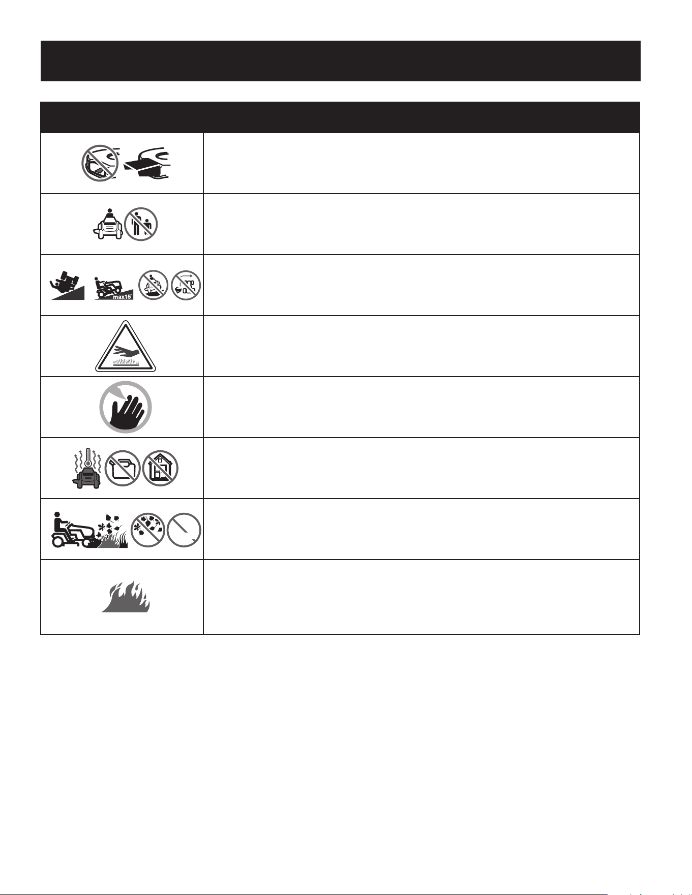
Symbol Description
READ THE OPERATOR’S MANUAL(S)
Read, understand, and follow all instructions in the manual(s) before attempting to assemble and
operate
DANGER— ROTATING BLADES
Never carry passengers. Never carry children, even with the blades off.
DANGER— ROTATING BLADES
Mowing in reverse is not recommended.
WARNING— ROTATING BLADES
Do not put hands or feet near rotating parts or under the cutting deck. Contact with the blade(s)
can amputate hands and feet.
DANGER— ROTATING BLADES
Always look down and behind before and while backing to avoid a back-over accident.
WARNING—THROWN OBJECTS
This machine may pick up and throw and objects which can cause serious personal injury.
6
SAFETY INSTRUCTIONS
Symbol Description
DANGER — SAFETY DEVICES
Keep safety devices (guards, shields, switches, etc.) in place and working.
BYSTANDERS
Keep bystanders, helpers, children and pets at least 75 feet from the machine while it is in
operation.
WARNING— SLOPE OPERATION
Do not operate this machine on a slope greater than 15 degrees. Do not mow across slopes. Mow
up and down slopes no greater than 15 degrees. Avoid sudden turns. Use low speed. If machine
stops going uphill, stop blades and back down slowly.
WARNING— HOT SURFACE
Engine parts, especially the muffler, become extremely hot during operation. Allow engine and
muffler to cool before touching.
DANGER — ROTATING BLADES
To reduce the risk of injury, keep hands and feet away. Do not operate unless discharge cover or grass
catcher is in its proper place. If damaged, replace immediately.
WARNING — FIRE HAZARD
Allow machine to cool before fueling or storing.
max10"
WARNING — FIRE HAZARD
Do not drive through piles of dry leaves or tall grass. Keep machine free of debris.
WARNING — FIRE HAZARD
Operation of this equipment may create sparks that can start fires around dry vegetation. A spark
arrestor may be required. The operator should contact local fire agencies for laws or regulations
relating to fire prevention requirements. Do not allow debris to accumulate. The build up of debris
can lead to a fire.
7
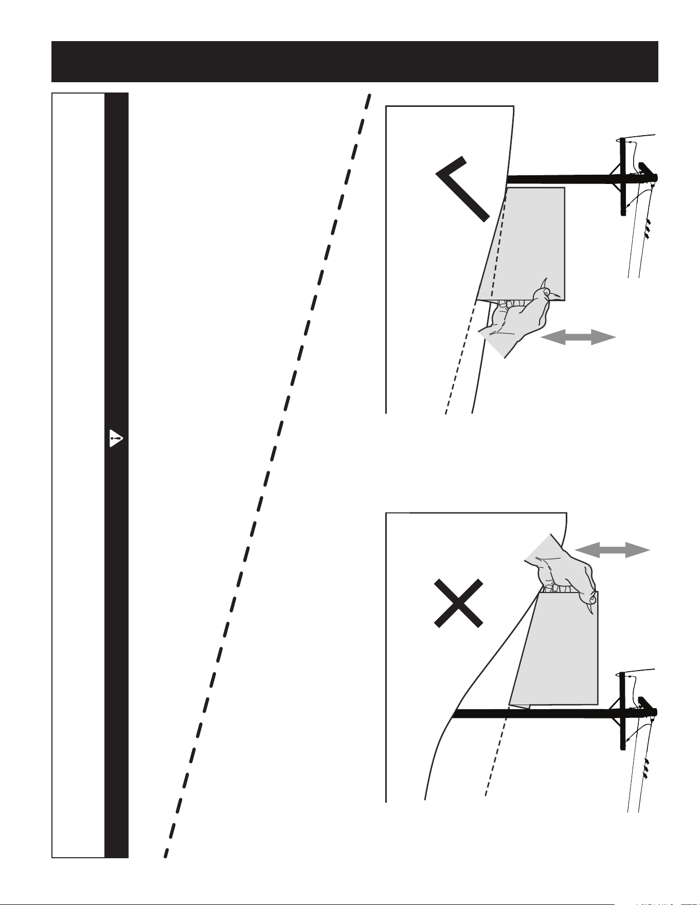
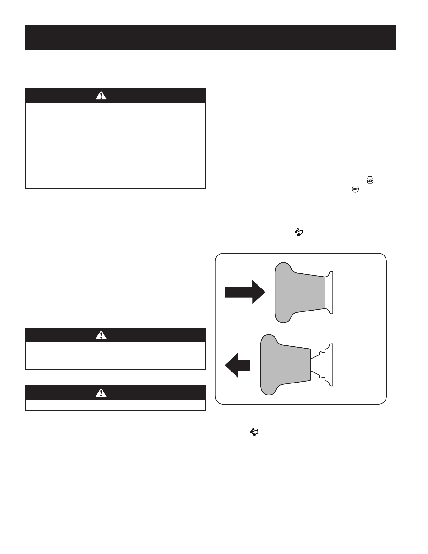
SLOPE GAUGE
(OK) (TOO STEEP)
USE THIS SLOPE GAUGE TO DETERMINE
IF A SLOPE IS TOO STEEP FOR SAFE OPERATION!
To check the slope, proceed as follows:
1. Remove this page and fold along the dashed line.
2. Locate a vertical object on or behind the slope (e.g. a pole, building, fence, tree, etc.)
3. Align either side of the slope gauge with the object (See Figure 1 and Figure 2 ).
4. Adjust gauge up or down until the left corner touches the slope (See Figure 1 and Figure 2).
5. If there is a gap below the gauge, the slope is too steep for safe operation (See Figure 2 above).
15° dashed line
Figure 2Figure 1
15° Slope
15° Slope
WARNING
Slopes are a major factor related to tip-over and roll-over accidents which can result in severe injury or death. Do not operate machine
on slopes in excess of 15 degrees. All slopes require extra caution. If you cannot back up the slope or if you feel uneasy on it, do not
mow it. Always mow up and down the face of slopes, never mow across the face of slopes.

8
TABLE OF CONTENTS
MODEL NUMBERPRODUCT SPECIFICATIONS
Safe Operation Practices .........................Page 3
Assembly ........................................Page 9
Operation ......................................Page 13
Service and Maintenance ........................Page 19
Off-Season Storage ............................. Page 30
Troubleshooting ................................Page 31
Español ........................................ Page 33
Warranty Statement ...............Separate Supplement
Engine Series: See Separate Engine Manual
Engine Oil Type: See Separate Engine Manual
Engine Oil Capacity: See Separate Engine Manual
Fuel: Unleaded Gasoline
Model Number ________________________________
Serial Number _________________________________
Date of Purchase _______________________________
Record the model number, serial number,
and date of purchase above.
9
ASSEMBLY
NOTE: All references in this manual to the left or right side and front or back of the
tractor are from the operating position only. Exceptions, if any, will be specified.
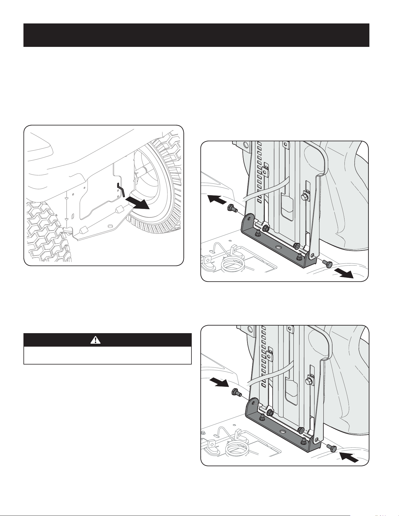
Tractor Preparation
Manually Moving the Tractor
1. Engage the transmission bypass rod to move the tractor manually without
starting it. The transmission bypass rod is located on the rear of the tractor,
on the frame. Engage the bypass rod by pulling out. See Figure 1.
Figure 1
NOTE: If the tractor will not move or does not move freely when pushing
check if the bypass lever is fully open or the brake is engaged.
NOTE: The transmission will NOT engage when the hydrostatic bypass rod
is pulled out. Return the rod to its normal position prior to operating the
tractor. If the tractor will not move when pushing on the forward/reverse
pedals, or moves slowly, check to see of the bypass valve is on.
CAUTION
Never tow your tractor. Towing the tractor with the rear wheels on the
ground may cause severe damage to the transmissions.
2. Disengage the bypass rod by pushing the rod back in after moving the
tractor. See Figure 1.
Install Operator’s Seat (If necessary)
To install the seat proceed as follows:
NOTE: The seat is shipped with the seat switch and seat pan attached.
1. Cut any straps securing the seat assembly to the tractor. Remove any packing
material.
NOTE: Be careful not to cut the wiring harness connecting the seat and the
seat switch.
2. Remove the two shoulder screws and flange lock nuts in the seat pan as
shown in Figure 2.
Figure 2
3. Rotate the seat into position and secure the seat into place with the
previously removed shoulder screws and flange lock nuts. Be careful not to
crimp or damage the wire harness while installing the seat. See Figure 3.
Figure 3
10
ASSEMBLY
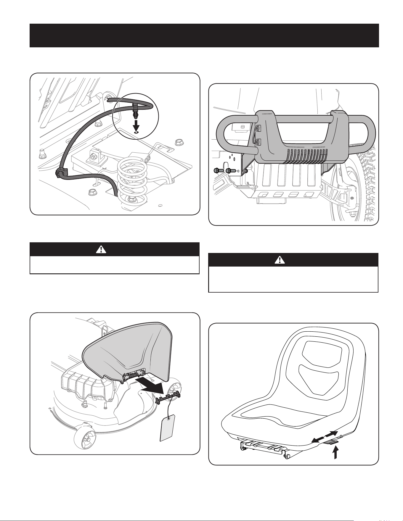
4. Using the harness clip attached to the harness, secure the excess wire to the
fender by snapping the harness clip in place as shown in Figure 4.
Figure 4
Lower Deck Discharge Chute Deflector
WARNING
Never operate the mower deck without the chute deflector installed and in
the down position.
Check the mower deck for a shipping brace that may be holding the chute deflector
upward for shipment. If the brace is present, it must be removed before operating
the tractor. Holding the chute deflector fully upward, remove the shipping brace.
Lower the chute deflector. See Figure 5.
Figure 5
Installing the Front Bumper (If equipped)
The hardware for attaching the front bumper is shipped installed into the bumper.
1. Remove the four hex screws from the bumper.
2. Position the bumper brackets to the inside of the tractor’s frame and secure
it in place with the four hex flange screws. See Figure 6.
Figure 6
Adjusting the Seat
WARNING
Before operating the tractor, make sure the seat is engaged in the seat-
stop. Engage the parking brake. Stand behind the machine and pull back
on seat until it clicks into place.
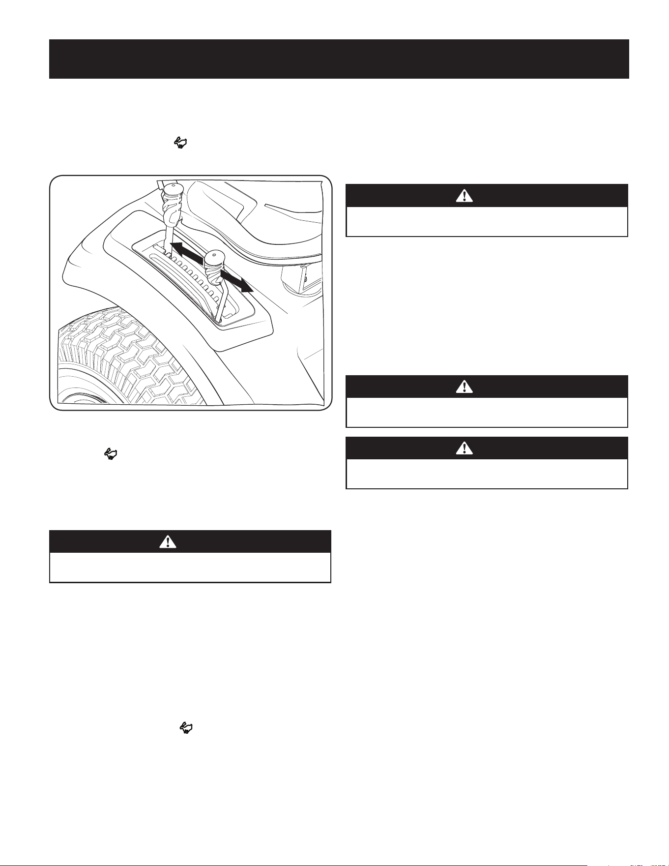
To adjust the position of the seat, lift the seat adjustment lever up. Slide the seat
forward or rearward to the desired position; then release the adjustment lever.
Make sure seat is locked into position before operating the tractor. See Figure 7.
Figure 7
11
ASSEMBLY
Checking Tire Pressure
WARNING
Equal tire pressure should be maintained at all times. Refer to the tire
sidewall for proper pressure.
The tires on your tractor may be over-inflated for shipping purposes. Reduce the tire
pressure before operating the tractor.
The recommended operating tire pressure is 14 psi for the front and rear tires
NOTE: Equal tire pressure is critical for level cutting deck performance.
Connecting the Battery Cables
WARNING
CALIFORNIA PROPOSITION 65 WARNING: Battery posts, terminals, and related
accessories contain lead and lead compounds, chemicals known to the State of
California to cause cancer and reproductive harm. Wash hands after handling.
CAUTION
When attaching battery cables, always connect the POSITIVE (Red) wire to
its terminal first, followed by the NEGATIVE (Black) wire.
For shipping reasons, both battery cables on your equipment may have been left
disconnected from the terminals at the factory. To connect the battery cables,
proceed as follows:
NOTE: The positive battery terminal is marked Pos. (+). The negative battery
terminal is marked Neg. (–).
NOTE: If the positive battery cable is already attached, skip ahead to step 2.
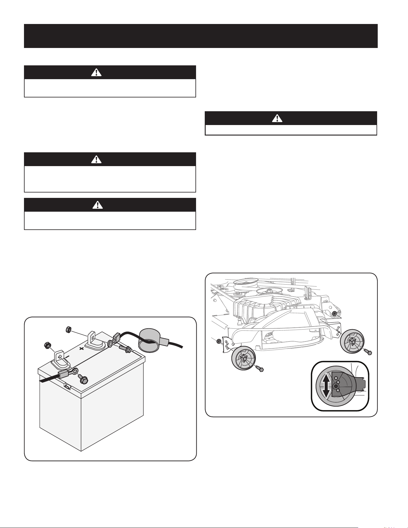
1. Remove the plastic cover, if present, from the positive battery terminal and
attach the red cable to the positive battery terminal (+) with the bolt and
hex nut. See Figure 8.
Figure 8
2. Remove the plastic cover, if present, from the negative battery terminal and
attach the black cable to the negative battery terminal (–) with the bolt and
hex nut. See Figure 8.
3. Position the red rubber boot over the positive battery terminal to help
protect it from corrosion.
NOTE: If the battery is put into service after the date shown on top/side
of battery, charge the battery as instructed in the Service section your
Operator’s Manual prior to operating the tractor.
Setting the Deck Wheels
WARNING
Keep hands and feet away from the discharge opening of the cutting deck.
NOTE: The deck wheels are an anti-scalp feature of the deck and are not designed to
support the weight of the cutting deck.
Move the tractor on a firm and level surface, preferably pavement, and proceed as follows:
1. Check the tire pressure, make sure the pressure is correct and equal on all tires.
2. Make sure the deck is level, both front-to-back and side-to-side. See the
Maintenance & Adjustments section for deck leveling information and instructions.
3. Select the height position of the cutting deck by placing the deck lift lever in
the normally desired mowing height setting.
4. Check the wheels for contact or excessive clearance with the surface below.
The deck wheels should have between ¼” and ½” clearance above the
ground. Proceed as follows to adjust the wheels:
a. Raise the deck lift handle to its highest setting.
b. Remove the front and rear deck wheels by removing the flange lock
nuts and shoulder bolts that secure them to the deck. See Figure 9.
Figure 9
c. Place the deck lift lever in the desired mowing height setting.
d. Reinsert the shoulder bolt (with each deck wheel) into the index
hole that leaves approximately ½-inch between the bottom of the
wheel and the pavement. Tighten the flange lock nut and shoulder
bolt to between 25-30 ft-lbs using a torque wrench.
NOTE: Refer to Adjusting the Deck in the Maintenance & Adjustments section of
this manual for more detailed instructions regarding various deck adjustments.

12
ASSEMBLY
Gas and Oil
Fuel Recommendations
Use automotive gasoline (unleaded or low leaded to minimize combustion chamber
deposits) with a minimum of 87 octane. Gasoline with up to 10% ethanol or 15%
MTBE (Methyl Tertiary Butyl Ether) can be used. Never use an oil/gasoline mixture
or dirty gasoline. Avoid getting dirt, dust, or water in the fuel tank. DO NOT use E85
gasoline.
• Refuel in a well-ventilated area with the engine stopped. Do not smoke or
allow flames or sparks in the area where the engine is refueled or where
gasoline is stored.
• Do not overfill the fuel tank. After refueling, make sure the tank cap is closed
properly and securely.
• Be careful not to spill fuel when refueling. Spilled fuel or fuel vapor may ignite.
If any fuel is spilled, make sure the area is dry before starting the engine.
• Avoid repeated or prolonged contact with skin or breathing of vapor.
Adding Fuel
WARNING
Use extreme care when handling gasoline. Gasoline is extremely
flammable and the vapors are explosive. Never fuel the riding mower
indoors or while the engine is hot or running. Extinguish cigarettes, cigars,
pipes and other sources of ignition.
1. Be sure engine is outdoors and in a well-ventilated area.
2. Clean area around the fuel fill cap and remove the fuel fill cap.
3. Using an approved red GASOLINE container, add fuel slowly, being careful to
avoid spilling.
4. Fill the tank until the fuel reaches the bottom of the fuel tank neck.
5. Replace the fuel cap and tighten securely. Wipe up spilled fuel before
starting engine. If fuel is spilled DO NOT start engine. Move riding mower
away from area of spillage. Avoid creating any source of ignition until fuel
vapors are gone.
Checking and Adding Oil
Your riding mower is shipped with oil in the engine. However, you MUST check
the oil level before operating. Check and add the oil as instructed in your Engine
Operator’s Manual.
CAUTION
Always check the engine oil level before each use as instructed in the engine
operator’s manual. Add oil as necessary. Failure to do so may result in serious
damage to your engine.
Smart Lawn App Bluetooth® Activation (If Equipped)
Take command of your lawn care with the Bluetooth® enabled Smart Lawn App
from Craftsman. Maintenance tips, weather tracking and more — everything
you need to keep the best yard on the block is now in one place. Smart Lawn also
provides step-by-step instructions and video tutorials to show you how to keep your
riding mower running right. Plus, you can order the parts you need directly from
the app. The app also tracks the charge of your riding mower battery, as well as the
state of other key replacement components like oil, blade and air filter.
Connect your Bluetooth® enabled riding mower by downloading the FREE
Craftsman Smart Lawn App to begin using all of the new connectivity features
of your Craftsman rider! Download it for FREE from the App Store or Google Play
(works with devices running iOS 9, Android 4.4 and later versions).
First, set your smartphone Bluetooth® setting to the ‘ON’ position. Next, you will
need to create your account. The app will prompt you to enter your riding mower’s
model number and serial number. Next it will attempt to connect with the riding
mower via Bluetooth®.
In order to sync your phone to the riding mower, start your mower so the engine
is running, keep your device within 150 feet of the mower, and make sure your
mower’s battery is fully charged. Remember to turn the key to the ’OFF’ position
after you connect so as not to drain the battery charge (if not running the riding
mower).
11
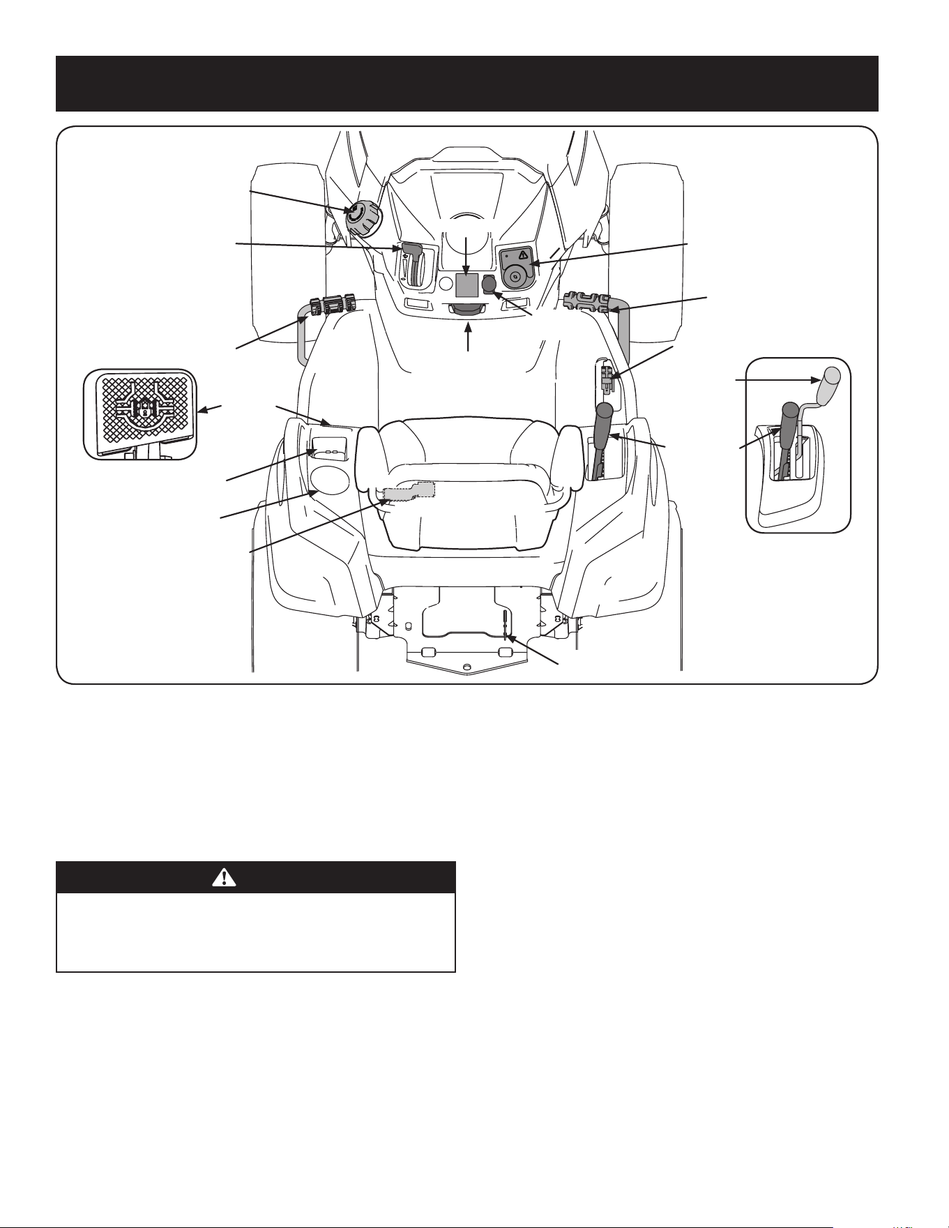
OPERATION
Manual
PTO Handle
Fuel Tank Cap
Throttle/Choke
Control Lever
Brake Pedal
Storage Tray
Cup Holder
Seat Adjustment Lever
Transmission
Bypass Rod
Deck Lift Lever
Reverse Drive Pedal
Forward Drive Pedal
Park Brake/Cruise
Control Lever
Ignition Module
Electric
PTO Switch
Hour Meter
Manual
PTO Models
Differential
Lock Pedal
Figure 10
Now that you have set up your riding mower, it’s important to become acquainted
with its controls and features. Refer to Differential.
NOTE: This Operator’s Manual covers several models. Tractor features may vary by
model. Not all features in this manual are applicable to all tractor models and the
tractor depicted may differ from yours.
NOTE: References to LEFT, RIGHT, FRONT, and REAR indicate that position on the
tractor when facing forward while seated in the operator’s seat.
WARNING
Read and follow all safety rules and instructions in this manual, including
the entire Operation section, before attempting to operate this machine.
Failure to comply with all safety rules and instructions may result in
personal injury.
Forward Drive Pedal
The forward drive pedal is located on the right side of the machine, along the
running board. Press the forward drive pedal forward to cause the tractor to travel
forward. Ground speed is also controlled with the forward drive pedal. The further
forward the pedal is pivoted, the faster the tractor will travel. The pedal will return
to its original/neutral position when it’s not pressed.
Reverse Drive Pedal
The reverse drive pedal is located on the right side of the tractor along the running
board. Ground speed is also controlled with the reverse drive pedal. The further
downward the pedal is pivoted, the faster the tractor will travel. The pedal will
return to its original/neutral position when it’s not pressed.
Brake Pedal
The brake pedal is located on the left side of the tractor, along the running board.
The brake pedal can be used for stopping the tractor or setting the parking brake.
NOTE: The brake pedal must be fully depressed to activate the safety
interlock switch when starting the tractor.
Differential Lock Pedal (if equipped)
The differential lock pedal is located on the left of the tractor to the rear of the running
board near the seat box. Activating the differential lock increases traction by maintaining
equal wheel speed on the rear tires. See the Differential Lock section for more
information on using the differential lock.
Seat Adjustment Lever
The seat adjustment lever is located below the left of the seat. The lever allows for
adjustment forward or backward of the operator’s seat. Refer to the Assembly &
Set-Up section for instructions on adjusting the seat position.
12
OPERATION
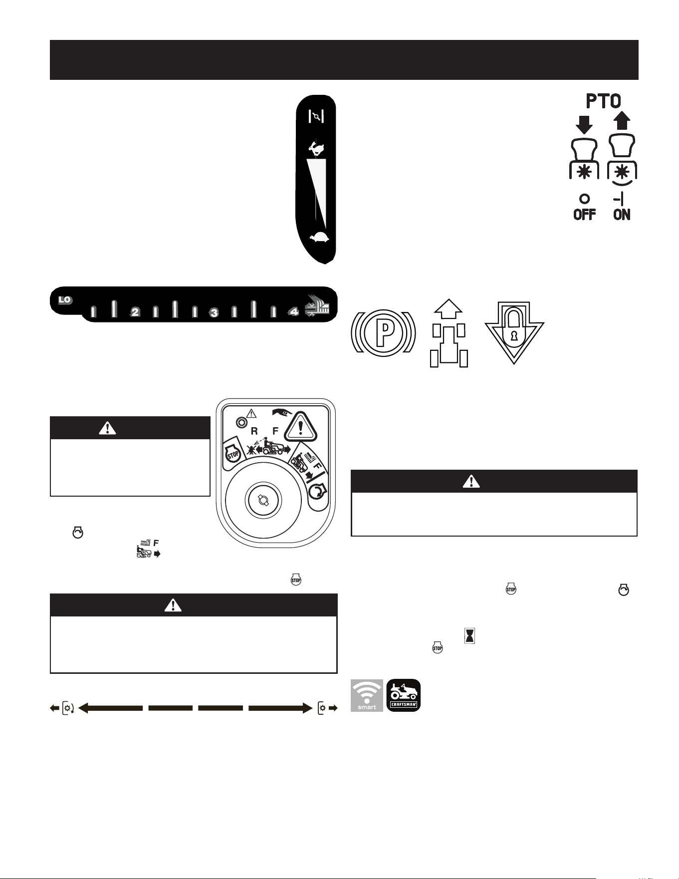
Throttle/Choke Control Lever
The throttle/choke control lever is located on the left side of the
tractor’s dash panel. This lever controls the speed of the engine and,
when pushed all the way forward, past the detent position closes the
choke for cold starting. When set in a given position, the throttle will
maintain a uniform engine speed.
NOTE: When operating the tractor with the cutting deck
engaged, be certain that the throttle/choke control is always in
the FAST position.
Deck Lift Lever
The lift lever is located in the right fender and is used to raise and lower the deck.
Pull the handle to the left out of the index notch and push downward to lower the
deck, or pull upward to raise the deck. When the desired height is attained, move
the lift handle to the right until fully in the index notch.
Ignition Module
WARNING
Never leave a running machine
unattended. Always disengage PTO, set
parking brake, stop engine and remove
key to prevent unintended starting.
To start the engine, insert the key into the
ignition switch and turn clockwise to the
START position. Release the key into the
NORMAL MOWING MODE position once
the engine has fired.
To stop the engine, turn the ignition key counterclockwise to the STOP position.
CAUTION
Prior to operating the tractor, refer to both Safety Interlock Switches and
Starting The Engine in the Operation section of this manual for detailed
instructions regarding the Ignition Switch Module and operating the
tractor in REVERSE CAUTION MODE
Manual PTO (Blade Engage) Handle
The PTO/blade engage handle is located on the right fender. Activating the PTO
engages power to the cutting deck or other (separately available) attachments. See
the Operation section for information and instructions on using the PTO.
Note: PTO stands for Power Take-Off, which is a mechanism for taking power from a
power source, such as a running engine and transmitting it to an application such as
the cutting blade of this riding mower.
Electric PTO (Blade Engage) Switch
The PTO switch is located on the dash panel to the right of the
LCD Service Minder & Hour Meter.
Activating the PTO engages power to the cutting deck or other
(separately available) attachments.
Transmission Bypass Rod
The transmission bypass rod is located at the rear of the tractor
on the lower right section of the frame.
When engaged, the rod opens a bypass within the hydrostatic transmissions, which
allows the tractor to be pushed short distances by hand. Refer to the Assembly &
Set-Up section for instructions on using the bypass feature.
Park Brake/Cruise Control Lever
Located in the center of the tractor’s dash panel below the steering wheel, the park brake/
cruise control lever is used to engage the parking brake and the cruise control. Refer to the
Operation section of this manual for detailed instructions regarding the parking brake.
NOTE: The parking brake must be set if the operator leaves the seat with the
engine running or the engine will automatically shut off.
NOTE: Cruise control can NOT be engaged at the tractor’s fastest ground speed.
WARNING
Never leave a running machine unattended. Always disengage the PTO,
set the parking brake, stop the engine and remove the key to prevent
unintended starting.
LCD Service Minder & Hour Meter w/ Smart Lawn App
Bluetooth® Activation (If Equipped)
When the ignition key is rotated out of the STOP position but not into the START
position, the LCD Service Minder and Hour Meter will briefly display the battery voltage,
followed by the tractor’s accumulated hours.
NOTE: Hours of tractor operation are recorded any time the ignition key is
rotated out of the STOP position, regardless of whether the engine is started.
Smart Lawn App (If Equipped)
The app’s automated maintenance dashboard and log will help you keep your machine
running at peak performance and protect your investment by tracking total hours
across the lifetime of your equipment.
Receive alert notifications when it’s time to perform essential maintenance tasks.
Your dashboard provides real time monitoring and indicates when it’s time for you
to check or change the oil, air filter, blades or battery. The app also enables you to
locate and contact service centers, access step-by-step instructions to perform routine
maintenance and purchase replacement parts directly from your mobile device.

13
OPERATION
Change Oil
The LCD will display the letters “CHG”, followed by the letters “OIL”, followed by the
letters “SOON”, then finally followed by the meter’s accumulated time. “CHG/OIL/SOON/
TIME” will alternate on the display for 7 minutes after the meter reaches 50 hours. This oil
service minder interval will occur every 50 hours. Before the interval expires, change the
engine oil as instructed in the Maintenance section of the Engine Operator’s Manual.
Low Oil (If so equipped)
The letters “LO” followed by the letters “OIL”, then followed by the meter’s accumulated
time will indicate the tractor is low on oil. When an engine is not running and
immediately after the engine is started the oil pressure may be low. This can trigger
the “LO” “OIL” text. This is normal. If the low oil indication persists stop the tractor
immediately and check the engine oil level as instructed in the Engine Operator’s Manual.
NOTE: The “LOW OIL” function only works if the engine is equipped with an
oil pressure switch.
Low Battery
At startup, the battery voltage is briefly displayed then changes to accumulated
hours. The letters “LO” will display followed by the letters “BATT” and then followed
by the meter’s accumulated time. “LO/BATT/TIME” is displayed on the LCD when the
voltage drops below 11.5 volts. When this occurs, the battery is in need of a charge
or the engine’s charging system is not generating sufficient amperage. Charge the
battery as instructed in the Service section of this manual or have the charging
system checked by your local service dealer.
Air Filter Service
The letters “CLN” will display, followed by the letters “AIR”, followed by “FILT”, then
followed by the meter’s accumulated time. “CLN/AIR/FILT/TIME” will alternate on
the display for 7 minutes after the meter reaches 50 hours. This air filter service
minder time interval will be every 50 hours. On intervals that are common with oil
service, the oil message will be displayed first followed by the air filter message.
Operation
WARNING
Avoid serious injury or death. Go up and down slopes, not across. Avoid
sudden turns. Do not operate the tractor where it could slip or tip. If machine
stops going uphill, stop the PTO and back down the hill safely. Keep safety
devices (guards, shields and switches) in place and working. Remove objects
that could be thrown by the blades. Know the location and function of all
controls. Be sure the blades and the engine are stopped before placing hands
or feet near blades. Before leaving the operator’s position, disengage the
PTO, engage parking brake, shut off the engine and remove the key.
Safety Interlock Switches
This tractor is equipped with a safety interlock system for the protection of the
operator. If the interlock system should ever malfunction, do not operate tractor.
Contact your authorized service dealer.
• The safety interlock system prevents the engine from cranking or starting
unless the parking brake is engaged, and the PTO is in the DISENGAGED (OFF)
position.
• The engine will automatically shut off if the operator leaves the seat before
engaging the parking brake.
• The PTO clutch will automatically shut off if the operator leaves the tractor’s
seat with the PTO in the ENGAGED (ON) position, regardless of whether the
parking brake is engaged
• With the ignition key in the NORMAL MOWING position, the PTO
clutch will automatically shut off if the PTO is moved into the ENGAGED (ON)
position with the drive pedal in position for reverse travel.
WARNING
Do not operate the tractor if the interlock system is malfunctioning. This
system was designed for your safety and protection.
Starting the Engine
WARNING
Do not operate the tractor if the interlock system is malfunctioning. This
system was designed for your safety and protection.
NOTE: Refer to the Assembly & Set-up section of this manual for Gasoline and Oil
fill-up instructions.
1. Insert the tractor key into the ignition switch module.
2. Place the PTO in the disengaged (OFF) position.
3. Fully engage the tractor’s brake.
4. Move the throttle/choke control into the CHOKE position.
NOTE: If the engine is warmed up, it may not be necessary to choke the engine.
5. Turn the ignition key clockwise to the START position. After the engine
starts, release the key. It will return to the NORMAL MOWING
position.
CAUTION
Do NOT hold the key in the START position for longer than ten seconds at a
time. Doing so may cause damage to your engine’s electric starter.
6. After the engine starts, move the throttle/choke control (if so equipped)
down into the FAST position or push the choke control (if so equipped)
down/in the OFF position.
NOTE: Do NOT leave the choke control on while operating the tractor. Doing
so will result in a “rich” fuel mixture and cause the engine to run poorly and
can damage the engine.
NOTE: When operating the tractor be certain that the throttle lever is always
in the FAST position. Operating with the throttle at less than full throttle
may lead to shortened battery life.
Stopping the Engine
WARNING
If you strike a foreign object, stop the engine and disconnect the spark
plug wire(s). Thoroughly inspect the machine for any damage. Repair the
damage before restarting and operating.
1. If the blades are ENGAGED (ON), place the PTO in the DISENGAGED (OFF)
position.
2. Place the throttle near the SLOW position.
3. Engage the parking brake.
4. Turn the ignition key counterclockwise to the STOP position.
5. Remove the key from the ignition switch to prevent unintended starting.
14
OPERATION
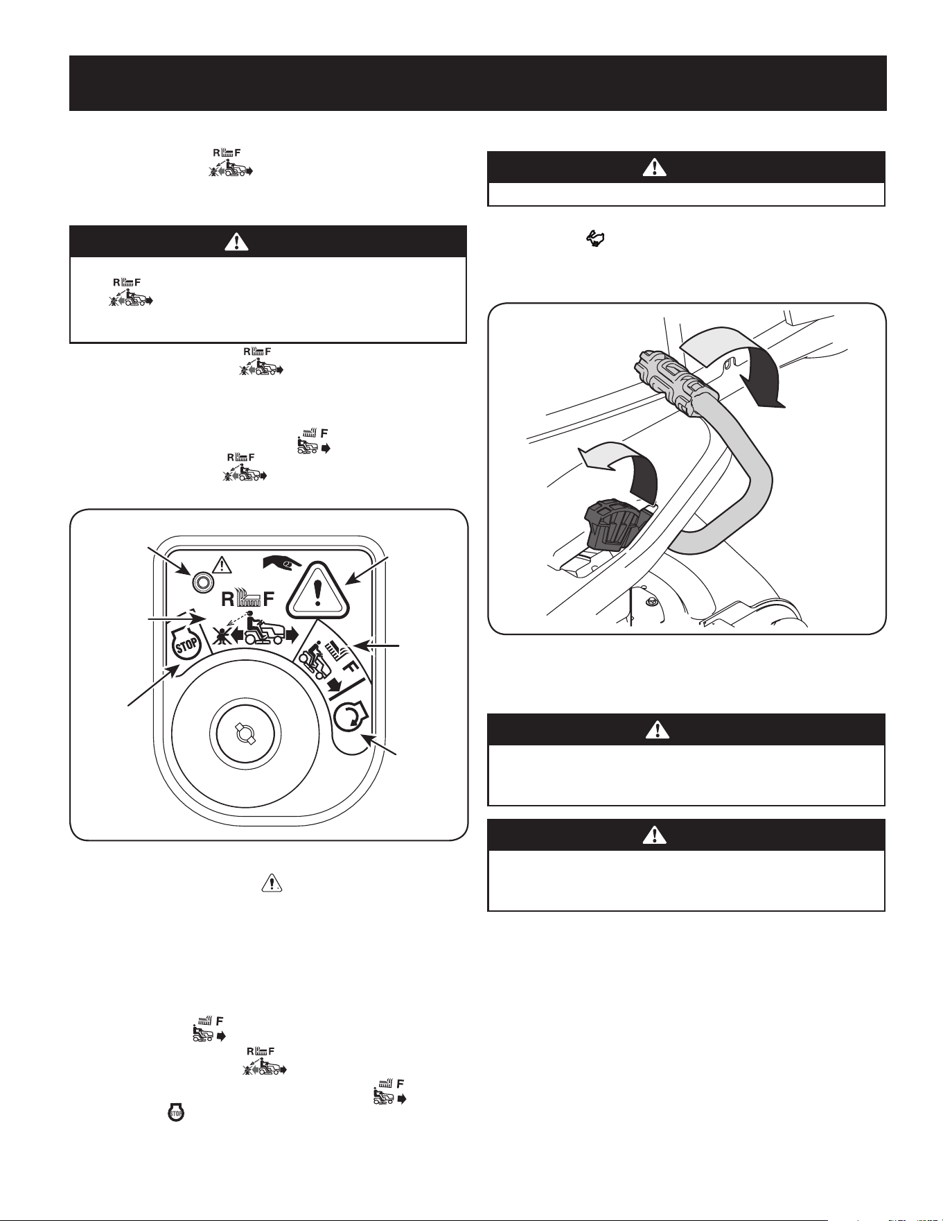
Reverse Caution Mode
The REVERSE CAUTION MODE position of the ignition module allows the
tractor to be operated in reverse with the blades (PTO) engaged.
NOTE: Mowing in reverse is not recommended.
WARNING
Use extreme caution while operating the tractor in the REVERSE CAUTION
MODE . Always look down and behind before and while backing.
Do not operate the tractor when children or others are around. Stop the
tractor immediately if someone enters the area.
To use the REVERSE CAUTION MODE :
NOTE: The operator MUST be seated in the tractor seat.
1. Start the engine as previously instructed on the previous page.
2. Turn the key from the NORMAL MOWING (Green) position to the
REVERSE CAUTION MODE (Yellow) position of the ignition module.
See Figure 11.
Start
position
Indicator
Light
Reverse
Push
Button
Normal
Driving
Mode
Stop
position
Reverse
Caution
Mode
Position
Figure 11
3. Press the REVERSE PUSH BUTTON at the top, right corner of the ignition
module. The red indicator light at the top, left corner of the ignition module
will be ON while activated. See Figure 11.
4. Once activated (indicator light ON), the tractor can be driven in reverse with
the cutting blades (PTO) engaged.
5. Always look down and behind before and while backing to make sure no
children are around. After resuming forward motion, return key to the
NORMAL MOWING position.
6. The REVERSE CAUTION MODE will remain activated until:
a. The key is placed in either the NORMAL MOWING position or
STOP position or
b. The operator leaves the seat (electric PTO)/the parking brake is set
(manual PTO).
Driving The Tractor
WARNING
Avoid sudden starts, excessive speed and sudden stops.
1. Lightly press the brake pedal to release the parking brake. Move the throttle
into the FAST position.
2. To travel FORWARD, slowly press the forward drive pedal forward until the
desired speed is achieved. See Figure 12.
Forward
Reverse
Figure 12
3. To travel in REVERSE, check that the area behind is clear then slowly depress
the reverse drive pedal until the desired speed is achieved. See Figure 12.
CAUTION
Do NOT attempt to change the direction of travel when the tractor is in
motion. Always bring the tractor to a complete stop before changing from
forward to reverse or vice versa.
WARNING
Do not leave the seat of the tractor without first placing the PTO in the
DISENGAGED (OFF) position and engaging the parking brake. If leaving the
tractor unattended, also turn the engine off and remove the ignition key.
15
OPERATION
Driving On Slopes
Refer to the SLOPE GAUGE on page 8 to help determine slopes where you may
operate the tractor safely.
WARNING
Do not mow on inclines with a slope in excess of 15 degrees (a rise of
approximately 2-1⁄2 feet every 10 feet). The tractor could overturn and
cause serious injury. Mow up and down slopes, NEVER across. Exercise
extreme caution when changing direction on slopes. Watch for holes, ruts,
bumps, rocks, or other hidden objects. Uneven terrain could overturn the
machine. Tall grass can hide obstacles. Avoid turns when driving on a slope.
If a turn must be made, turn down the slope. Turning up a slope greatly
increases the chance of a roll over. Avoid stopping when driving up a slope.
If it is necessary to stop while driving up a slope, start up smoothly and
carefully to reduce the possibility of flipping the tractor over backward.
Engaging the Parking Brake
NOTE: The parking brake must be set if the operator leaves the seat with the engine
running or the engine will automatically shut off.
To set the parking brake:
1. Press the brake pedal completely down with your left foot and hold it in that
position.
2. Press down on the parking brake/cruise control lever and hold it in that
position.
3. Remove your foot from the brake pedal.
4. Release pressure from the parking brake/cruise control lever.
5. After completing step 3, the brake pedal should remain in the down position.
If it doesn’t, the parking brake is not engaged. Repeat steps 1-4 to engage.
To disengage the parking brake, lightly press the brake pedal.
WARNING
Never leave a running machine unattended. Always disengage the PTO,
set the parking brake, stop the engine and remove the key to prevent
unintended starting.
Setting The Cruise Control
WARNING
Never engage the cruise control lever while traveling in reverse.
To set the cruise control:
1. Slowly press the forward drive pedal with your right foot until the desired
speed is achieved.
2. Press down on the parking brake/cruise control lever and hold it in that
position.
3. Remove your foot from the forward drive pedal.
4. Release pressure from the parking brake/cruise control lever.
5. After completing step 3, the forward drive pedal should remain in the down
position and the tractor will maintain the same forward speed. If it doesn’t, the
cruise control is not engaged. Repeat steps 1-4 to engage the cruise control.
To disengage the cruise control, lightly press the forward drive pedal or the brake
pedal.
NOTE: Cruise control can not be set at the tractor’s fastest ground speed.
If the operator should attempt to do so, the tractor will automatically
decelerate to the fastest optimal mowing ground speed.
To change the direction of travel from forward to reverse when cruise control is
engaged, press the brake pedal to disengage and bring the tractor to a complete stop.
Then slowly press the reverse drive pedal with the ball of your foot to travel in reverse.
Using the Deck Lift Lever
To raise or lower the cutting deck, move the lift lever to the left, then place it in the
notch best suited for your application.
Operating the Headlights
The lamps are ON whenever the ignition key is rotated out of the STOP position.
The lamps turn OFF when the ignition key is moved to the STOP position.
Engaging the PTO (Electric PTO tractors)
Engaging the PTO transfers power to the cutting deck or other (separately available)
attachments. To engage the PTO:
1. Move the throttle to the FAST position.
2. Pull the PTO switch up/out into the engaged (ON) position. See Figure 13.
ON
OFF
Figure 13
NOTE: When operating the tractor be certain that the throttle is always in
the FAST position. Operating with the throttle at less than full throttle
may lead to premature battery wear and a poor quality cut.
3. To disengage the PTO, push the PTO switch down/in to the disengaged (OFF)
position.
16
OPERATION
Engaging the PTO (Manual PTO tractors)
Engaging the PTO transfers power to the cutting deck or other (separately available)
attachments. To engage the PTO:
1. Move the throttle to the FAST position.
2. Push the PTO handle forward into the engaged (ON) position. See Figure 14.
Figure 14
NOTE: When operating the tractor be certain that the throttle is always in
the FAST position. Operating with the throttle at less than full throttle
may lead to premature battery wear and a poor quality cut.
To disengage the PTO, pull the PTO handle rearward into the disengaged (OFF)
position.
Mowing
WARNING
Make certain the area to be mowed is free of debris, sticks, stones, wire or
other objects that can be thrown by the rotating blades.
NOTE: Do not engage the mower deck when lowered in grass. Premature wear and
possible failure of the belt and PTO clutch will result. Fully raise the deck or move to
a non-grassy area before engaging the mower deck.
1. Mow up and down slopes, not across.
2. Avoid turns when driving on a slope. If a turn must be made, turn down the
slope. Turning up a slope greatly increases the chance of a roll over.
3. Avoid stopping when driving up a slope. If it is necessary to stop while
driving up a slope, start up the slope smoothly and carefully to reduce the
possibility of flipping the tractor over backward
4. Place the throttle into the FAST position and engage the PTO.
5. Lower the mower deck to the desired height setting using the deck lift handle.
6. Slowly press the forward drive pedal with your right foot until the desired
speed is achieved.
NOTE: The speed of the tractor will affect the quality of the mower cut.
Mowing at full speed will adversely affect the cut quality. Control the ground
speed with forward drive pedal.
7. When approaching the other end of the strip, slow down or stop before turning.
8. Align the mower with an edge of the mowed strip and overlap approximately 3”.
9. Direct the tractor on each subsequent strip to align with a previously cut strip.
10. To prevent rutting or grooving of the turf, if possible, change the direction
that the strips are mowed by approximately 45° for the next and each
subsequent mowing.
WARNING
Be careful when crossing gravel paths or driveways. Disengage the PTO and
raise the deck to the highest position before crossing.
NOTE: When stopping the tractor for any reason while on a grass surface,
always:
• Make sure the drive pedal is in neutral.
• Engage the parking brake.
• Shut the engine off and remove the key.
• Doing so will minimize the possibility of having your lawn
‘‘browned’’ by hot exhaust from your tractor’s running engine.
Using the Differential Lock (if equipped)
WARNING
When the differential lock is on, be sure to allow for a larger turning radius
and greater steering effort.
WARNING
Engage the differential lock only when the vehicle is stationary. Do not use
the differential lock when traveling downhill.
NOTE: The system should only be used when poor traction is encountered. It should
be disengaged when traveling on surfaces with adequate traction.
In some instances, the tractor may be driven in slippery or low-traction situations
and it may be necessary to activate the differential lock. To use the differential lock
proceed as follows.
1. Press down on the brake pedal to stop the motion of the tractor.
2. Press down on the differential lock pedal to engage the differential lock.
NOTE: The differential lock only works while the pedal is pressed.
3. Release the brake pedal to drive the tractor forward while differential lock is
engaged.
NOTE: Engagement may be delayed. The differential lock will engage when
different wheel speeds are detected.
NOTE: Disengagement may be delayed. The differential lock will disengage
when the rear wheel speeds allow it to release.
4. To disengage the differential lock, release the differential lock pedal.

19
SERVICE AND MAINTENANCE
MAINTENANCE SCHEDULE
WARNING
Before performing any type of maintenance/service, disengage all controls
and stop the engine. Wait until all moving parts have come to a complete
stop. Disconnect spark plug wire and ground it against the engine to
prevent unintended starting. Always wear safety glasses during operation
or while performing any adjustments or repairs.
Follow the maintenance schedule given below. This chart describes service guidelines
only. Use the Service Log column to keep track of completed maintenance tasks. To
locate the nearest authorized Service Center or to schedule service, call
the following toll free number: 1-888-331-4569.
Refer to the Engine Operator’s Manual for engine maintenance items listed in the table
below.
Interval Item Service Service Log
Each use 1. Engine intake screens and cooling
fans *
2. Exhaust manifold, muffler pipe and
muffler shields *
3. Check/Clean Hood/Dash Panel
Louvers *
4. Top and underside of deck, under and
around spindle covers and belt area *
5. Around fuses, wiring and wiring
harnesses *
6. Around transmission, axle and fans *
7. Engine Oil
8. Air Filter
1. Check/Clean
2. Check/Clean
3. Check/Clean
4. Check/Clean
5. Check/Clean
6. Check/Clean
7. Check (See engine manual)
8. Check (See engine manual)
After first 5 hours 1. Engine Oil 2. Change (break-in period). (See engine
manual)
Every 10 hours 1. Battery terminals
2. Hood/Dash panel louvers
3. Intake screen
4. Blades
5. Tires
6. Front wheels
7. Deck
1. Clean
2. Clean
3. Check/Clean
4. Check/Sharpen/Replace as needed
5. Check
6. Lube
7. Check/Clean
Every 25 hours 1. Deck wheels
2. Deck level/pitch
3. Lubrication points
1. Inspect and lube
2. Check
3. Grease
Every 50 hours 1. Belts and pulleys
2. Engine Oil
3. Oil Filter
4. Air Filter
5. Fuel Filter
1. Check for damage and wear
2. Change (See engine manual)
3. Replace (See engine manual)
4. Clean or change (See engine manual)
5. Replace (See engine manual)
Every 100 hours 1. Hardware
2. Spark plug condition/gap
1. Check and secure
2. Check (See engine manual)
Every season/Before storage 1. Engine Cooling Fans
2. Battery terminals
3. Lubrication points
4. Hood/Dash panel louvers
5. Intake screen
6. Blades
7. Tires
8. Deck
9. Deck wheels
10. Deck level/pitch\
11. Spark plug condition/gap
12. Engine Oil
13. Oil Filter
1. Check/Clean
2. Clean
3. Grease
4. Clean
5. Check/Clean
6. Check/Sharpen/Replace as needed
7. Check
8. Check/Clean
9. Inspect and lube
10. Check
11. Check (See engine manual)
12. Change (See engine manual)
13. Replace (See engine manual)
Miscellaneous 1. Valve lashing (camshaft/valve
clearance) ^
2. Check and adjust ^
*-- Perform more often in dry conditions and/or when mulching
^ -- Have this item performed by a qualified service dealer
20
SERVICE AND MAINTENANCE
NOTE: This Operator’s Manual covers several models. Tractor features may vary by
model. Not all features in this manual are applicable to all tractor models and the
tractor depicted may differ from yours.
WARNING
Before performing any maintenance or repairs, disengage the PTO, set the
parking brake, stop the engine and remove the key to prevent unintended
starting.
Post-Operation Tractor Care
After each operation of the tractor, the following procedures should be
implemented to extend the life of your tractor and ensure safe operating conditions.
DANGER
Failure to follow these recommendations may result in serious injury to
yourself or others and may cause damage to the tractor.
Cleaning the Underside of the Deck
Deck Wash System
Your tractor’s deck is equipped with a water port on its surface as part of its deck
wash system.
Use the Smart Jet to rinse grass clippings from the deck’s underside and prevent the
buildup of corrosive chemicals. Complete the following steps AFTER EACH MOWING:
1. Drive the tractor to a level, clear spot on your lawn, near enough for your
garden hose to reach.
WARNING
Make certain the tractor’s discharge chute is directed AWAY from people,
your house, garage, parked cars, etc.
2. Disengage the PTO, set the parking brake and stop the engine.
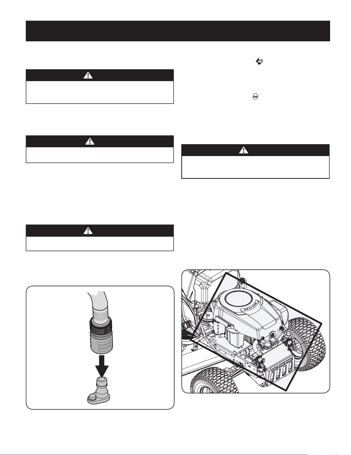
3. Thread the hose coupler (packaged with your tractor’s Operator’s Manual)
onto the end of your garden hose.
4. Attach the hose coupler to the water port on your decks surface. See Figure 15.
Figure 15
Note: Make sure that the hose is not routed under the deck and is clear of all
moving parts.
5. Turn the water on.
6. While sitting in the operator’s position on the tractor, start the engine and
place the throttle lever in the FAST position.
7. Move the tractor’s PTO into the engaged (ON) position.
8. Remain in the operator’s position with the deck engaged for a minimum of
two minutes, allowing the underside of the deck to thoroughly rinse.
9. Move the tractor’s PTO into the disengaged (OFF) position.
10. Turn the ignition key to the STOP position to turn the tractor’s engine off.
11. Turn the water off and detach the hose coupler from the water port on your deck’s
surface.
12. After cleaning your deck with the Smart Jet system, return to the operator’s
position and engage the PTO. Keep the deck running for a minimum of two
minutes, allowing the underside of the deck to thoroughly dry.
Cleaning the Tractor
WARNING
If the tractor has been recently run, the engine, muffler and surrounding
metal surfaces will be hot and can cause burns to the skin. Let the engine
cool for at least five minutes Exercise caution to avoid burns.
Your tractor should be cleaned after each use and under certain conditions, i.e. dry
conditions and/or mulching situations, additional cleaning may be necessary.
One of the best ways to keep your tractor running efficiently and to reduce fire risk
is to regularly remove debris buildup from the tractor. Follow the recommendations
below and contact your authorized dealer with any questions.
• Allow the machine to cool in an open area before cleaning.
• Do not use water on any part of the tractor except the underside of the
cutting deck. Doing so can cause damage to the tractor’s spindle bearings,
electrical system and engine, leading to premature failures. The use of
compressed air and/or leaf blower will help keep the tractor clean.
• Clean under the hood. Exhaust manifold, around fuses, all wiring and
harnesses, muffler pipe, muffler shield, engine intake screens and cooling
fins, etc. See Figure 16.
Figure 16
21
SERVICE AND MAINTENANCE
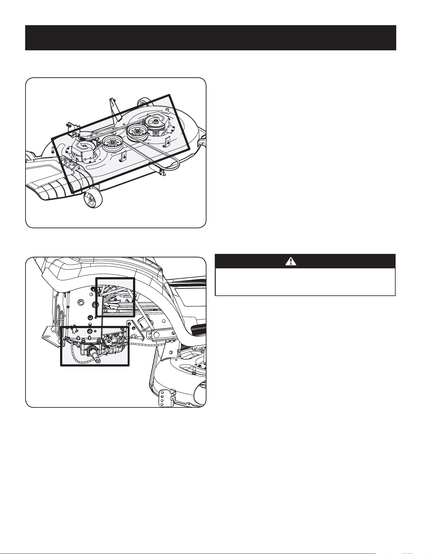
• Clean the top of the mower deck, under the spindle covers and belt area. See
Figure 17.
Figure 17
• Clean around and near the transmission, axle and the fan area. See Figure 18.
Wheel Not Shown For Clarity
Figure 18
• Debris can accumulate anywhere on the tractor, especially on horizontal
surfaces. Additional cleaning may be necessary when mowing in dry
conditions or when mulching.
• Fuel leaks/spills, oil leaks/spills and excess lubrication can also become
collection sites for debris. Immediate repair and cleaning up oil or fuel spills
can help reduce fire hazards.
• In addition to cleaning the tractor before operating and storing, do not
attempt to mow unusually tall grass (10” or higher), dry grass (e.g., pasture)
or piles of dry leaves. Dry grass or leaves may contact the engine exhaust
and/or build up on the mower deck presenting a potential fire hazard.
Storing the Tractor
• Allow the machine to cool in an open area before storing.
• Do not park the tractor near any flammable materials (wood, cloth or
chemicals) or any open flames or other potential source of ignition (furnace,
water heater or any other type of heater).
• Remove all combustible materials from the tractor before storing. Empty
cargo boxes, grass catchers or containers.
• Always shut off fuel flow when storing or transporting if tractor is equipped
with a fuel shutoff.
• Check the fuel system (lines, tank, cap and fittings) frequently for cracks or
leaks. Repair and clean as necessary.
Engine
Refer to the Engine Operator’s Manual for all engine maintenance procedures and
instructions for checking and adding oil. See the Changing the Engine Oil section
below for oil changing procedures and instructions.
NOTE: If the “LOW OIL” text appears immediately after the engine is started
the oil pressure may be low. This is normal. If the low oil indication persists
stop the tractor immediately and check the engine oil level as instructed in
the Engine Operator’s Manual.
NOTE: The “LOW OIL” function only works if the engine is equipped with an
oil pressure switch.
Changing the Engine Oil
WARNING
If the engine has been recently run, the engine, muffler and surrounding
metal surfaces will be hot and can cause burns to the skin. Exercise caution
to avoid burns.
To complete an oil change, proceed as follows:
1. Run the engine for a short time to warm the engine oil. The oil will flow more
freely and carry away more impurities. Use care to avoid burns from hot oil.
2. Locate the oil drain hose on the left side of the engine.
3. Place an appropriate oil collection container with at least a 2.5 quart capacity
below the opening of the oil drain tube, to collect the used oil. Remove the
oil fill cap/dipstick from the oil fill tube.
22
SERVICE AND MAINTENANCE
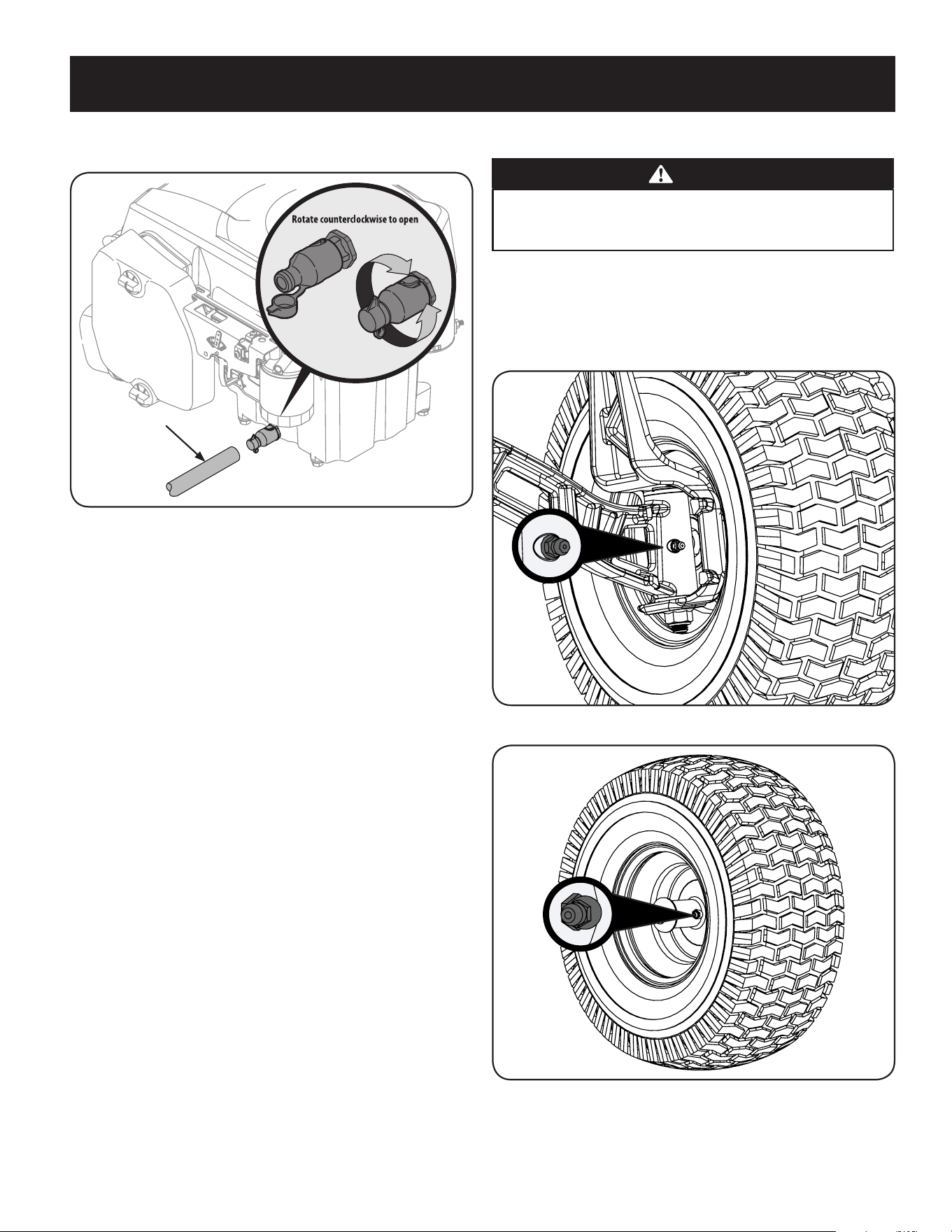
4. Pop open the protective cap on the end of the oil drain valve to expose the
drain port.
OPENED
CLOSED
Clear Oil Drain Tube
Figure 19
5. Remove the oil fill cap/dipstick from the oil fill tube.
6. Push the clear oil drain tube (packed with this manual) onto the oil drain
port. Route the opposite end of the tube into an appropriate oil collection
container with at least a 2.5 quart capacity to collect the used oil.
7. The engine is equipped with a twist-and-pull drain port. Turn the oil drain
valve 1⁄4-turn counter-clockwise, then pull outward to begin draining oil.
After the oil has finished draining, push the end of the oil drain valve back in
and turn 1⁄4-turn clockwise to secure it back in place. Re-cap the end of the
oil drain valve to keep debris from entering the drain port.
7. Replace the oil filter, and refill the engine with new oil as instructed in the
engine operator’s manual.
NOTE: Place an absorbent towel beneath the oil filter to keep oil off the clutch.
8. To refill the oil, re-install the plug at the end of the tube and refer to the
engine operator’s manual for refilling instructions, oil type and amount.
NOTE : Maintenance, repair, or replacement of the emission control devices
and systems which are being done at owner’s expense may be performed
by any engine repair establishment or individual. Warranty repairs must be
performed by an authorized dealer.
Hydrostatic Transmission
The hydrostatic transmission is sealed at the factory and is maintenance-free. The
fluid level cannot be checked and the fluid cannot be changed.
Hydrostatic Neutral Adjustment
If the tractor creeps forward or rearward when neither the forward nor reverse
pedal is depressed, contact your authorized dealer to have the neutral setting
properly adjusted.
Cleaning the Tractor
Any fuel or oil spilled on the machine should be wiped off promptly. Do NOT allow
debris to accumulate around the cooling fins of the engine, the transmission’s
cooling fan or on any other part of the machine.
Lubrication
WARNING
Before lubricating, repairing, or inspecting, always disengage the PTO,
set the parking brake, stop the engine and remove the key to prevent
unintended starting.
Front Wheels
Each of the front wheel axles and rims is equipped with a grease fitting. See Figure
20 for the location of the grease fitting on the axles and Figure 21 for the location of
the grease fitting on the rims. Lubricate with a No. 2 multi-purpose grease applied
with a grease gun after every 25 hours of tractor operation.
Figure 20
Figure 21
23
SERVICE AND MAINTENANCE
Deck Wheels
The wheels on the deck are equipped with a grease fitting. Lubricate with a No.
2 multi-purpose grease applied with a grease gun after every 25 hours of tractor
operation.
Pivot Points & Linkage
Lubricate all the pivot points on the drive system, parking brake and lift linkage at
least once a season with light oil.
Note: It is not necessary to grease the steering pinion/sector gear interface. Doing
so will allow dirt to accumulate and can affect steering performance.
Adjustments
WARNING
Shut the engine off, remove the ignition key and engage the parking brake
before making adjustments. Protect your hands by using heavy gloves
when handling the blades.
NOTE : Check the tractor’s tire pressure before performing any deck leveling
adjustments. Refer to Tires on page 11 for information regarding tire pressure.
Adjusting the Deck
Leveling the Deck (Front-To-Rear)
The front of the cutting deck is supported by a stabilizer bar that can be adjusted to
level the deck from front to rear. The front of the deck should be between 1⁄4-3⁄8”
lower than the rear of the deck. Adjust if necessary as follows:
1. Park the tractor on a firm, level surface and place the deck lift lever in the
middle position and rotate the blade nearest the discharge chute so that it is
parallel with the tractor.
2. Measure the distance from the front of the blade tip to the ground and the
rear of the blade tip to the ground. The front of the deck should be between
1⁄4-3⁄8” less than the rear of deck.
3. Determine the approximate distance necessary for proper adjustment and
proceed, if necessary.
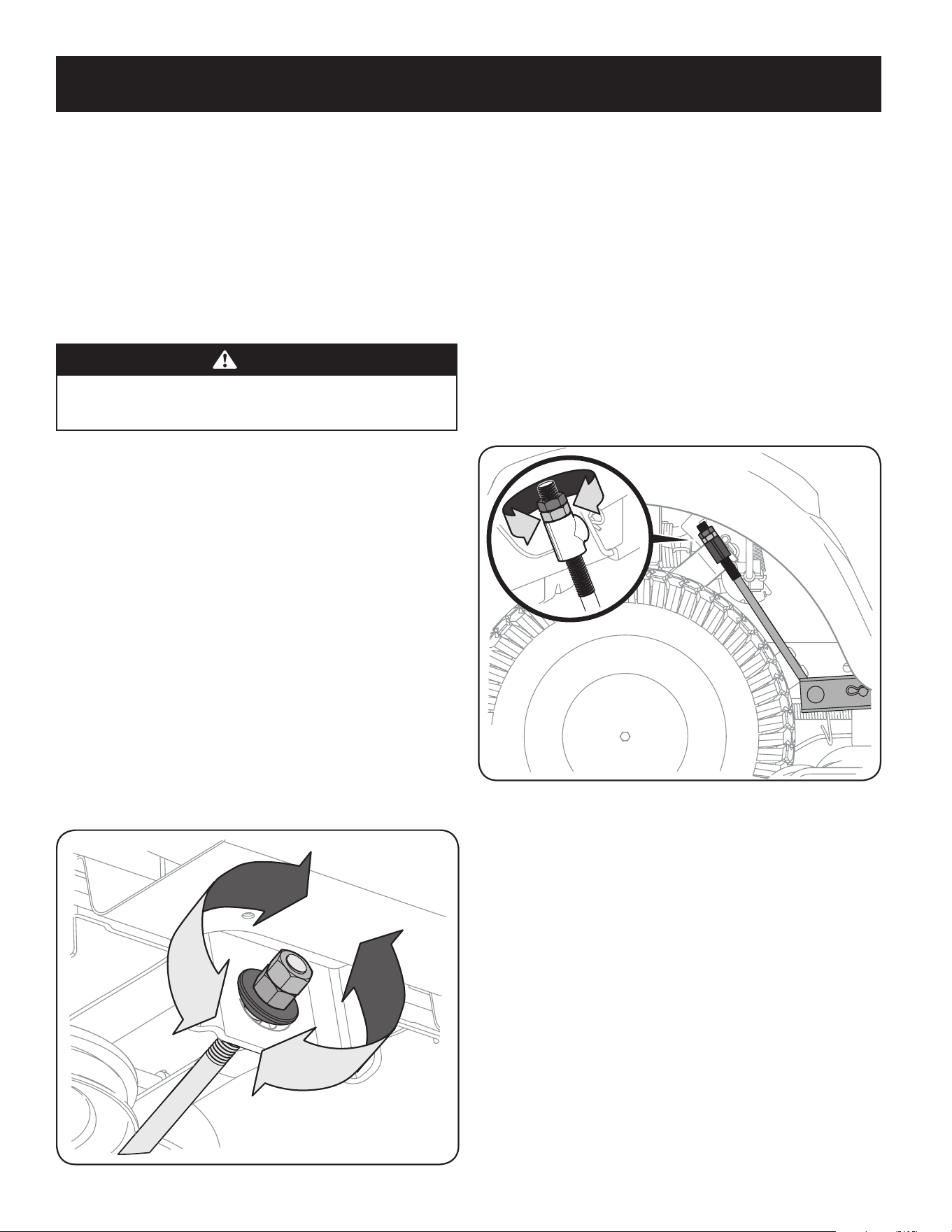
4. To raise the front of the deck, loosen the outer nut then tighten (thread
inward) the nut against the front hanger bracket. See Figure 22. When
proper adjustment is achieved, re-tighten the outer nut to 25-30 ft.-lbs.
Figure 22
5. To lower the front of the deck, loosen the outer nut then loosen (thread
outward) the nut, away from the front hanger bracket. See Figure 22. When
proper adjustment is achieved, re-tighten the outer nut.
Leveling the Deck (Side-to-Side)
If the cutting deck appears to be mowing unevenly, a side to side adjustment can be
performed. Adjust if necessary as follows:
1. With the tractor parked on a firm, level surface, place the deck lift lever in
the middle position and rotate both blades so that they are perpendicular
with the tractor.
2. Measure the distance from the outside of the left blade tip to the ground
and the distance from the outside of the right blade tip to the ground. Both
measurements taken should be equal. If they’re not, proceed to the next
step.
3. Under the rear fenders inside the wheels there is a lift adjustment rod for
each side of the deck. See Figure 23.
Figure 23
4. Minor side-to-side adjustments should be made using primarily the left
adjustment rod.
5. To raise the left side of the deck, loosen the upper nut on the end of the
lift rod, then turn the lower nut clockwise. When the proper adjustment is
achieved, tighten the upper nut to secure in place. To lower the left side of
the deck, loosen the upper nut on the end of the lift rod, then turn the lower
nut counterclockwise. When the proper adjustment is achieved, tighten the
upper nut to 25-30 ft-lbs. to secure in place.
6. The deck is properly leveled when both blade tip measurements taken earlier
are equal.
Adjusting the Deck Height
The height of the deck can be adjusted to ensure that the setting on your deck
height lever is accurate. To adjust the deck height proceed as follows:
1. Park the tractor on a firm, level surface and place the deck lift lever in the
highest position (4”) and rotate the blade nearest the discharge chute so that
it is perpendicular with the tractor.
2. Measure the distance from the outside of the left blade tip to the ground
and the distance from the outside of the right blade tip to the ground. Both
measurements taken should be 4”. If they’re not, proceed to the next step.

24
SERVICE AND MAINTENANCE
3. Using the right and left lift rods, raise or lower the necessary side of the deck
until both sides are measured at 4” from the pavement.
Adjusting the Deck Wheels
WARNING
Keep hands and feet away from the discharge opening of the cutting deck.
NOTE: The deck wheels are an anti-scalp feature of the deck and are not designed to
support the weight of the cutting deck.
The deck wheels should be approximately 1⁄4-1⁄2” above the ground when the deck
is set in the desired height setting. To adjust the deck wheels see the Assembly &
Set-Up section for instructions.
Seat Adjustment
Refer to the Assembly & Set-Up section of this manual for seat adjustment instructions.
WARNING
Before operating the tractor, make sure the seat is engaged in the seat-
stop. Engage the parking brake. Stand behind the machine and pull back
on seat until it clicks into place.
Parking Brake Adjustment
If the tractor does not come to a complete stop when the brake pedal is completely
depressed, or if the tractor’s rear wheels can roll with the parking brake applied
(and the hydrostatic relief valve open), the brake is in need of adjustment. See your
authorized service dealer to have the brake adjusted.
Wheel Alignment
If your tractor pulls to one side or is out of alignment, a wheel alignment might
be necessary. Take your tractor to an authorized service dealer to have the wheels
properly aligned.
Service
Battery
WARNING
California Proposition 65 Warning: Battery posts, terminals, and related
accessories contain lead and lead compounds, chemicals known to the State of
California to cause cancer and reproductive harm. Wash hands after handling.
CAUTION
If removing the battery, disconnect the NEGATIVE (Black) wire from its
terminal first, followed by the POSITIVE (Red) wire. When reinstalling
the battery, always connect the POSITIVE (Red) wire to its terminal first,
followed by the NEGATIVE (Black) wire.
The battery is sealed and is maintenance-free. Acid levels cannot be checked and
fluid can not be added.
• Always keep the battery cables and terminals clean and free of corrosive build-up.
• After cleaning the battery and terminals, apply a light coat of petroleum jelly
or grease to both terminals.
Jump Starting
WARNING
Never jump start a damaged or frozen battery. Be certain the vehicles do
not touch, and ignitions are off. Do not allow cable clamps to touch.
1. Connect positive (+) cable to positive (+)post of your tractor’s discharged
battery.
2. Connect the other end of the cable to the positive (+) post of the jumper
battery.
3. Connect the second cable negative (–) to the other post of the jumper battery.
4. Make the final connection on the engine block of the tractor, away from the
battery. Attach to an unpainted part to assure a good connection.
CAUTION
If the jumper battery is installed on a vehicle (i.e. car, truck), do NOT start
the vehicle’s engine when jump starting your tractor.
5. Start the tractor (as instructed in the Operation section of this manual).
6. Remove the jumper cables in reverse order of connection.
Charging
WARNING
Batteries give off an explosive gas while charging. Charge the battery in a
well ventilated area and keep away from an open flame or pilot light as on a
water heater, space heater, furnace, clothes dryer or other gas appliances.
CAUTION
When charging your tractor’s battery, use only a charger designed for 12V lead-
acid batteries. Read your battery charger’s Owner’s Manual prior to charging
your tractor’s battery. Always follow its instructions and heed its warnings.
If your tractor has not been put into use for an extended period of time, charge the
battery as follows:
1. Set your battery charger to deliver a max of 10 amperes.
2. If your battery charger is automatic, charge the battery until the charger
indicates that charging is complete. If the charger is not automatic, charge
for no fewer than eight hours.
Fuse
WARNING
Before servicing, repairing, or inspecting, always disengage PTO, set parking
brake, stop engine and remove key to prevent unintended starting.
A 20 AMP fuse is installed in your tractor’s wiring harness to protect the tractor’s
electrical system from damage caused by excessive amperage.
If the electrical system does not function, or your tractor’s engine will not crank,
check to be certain that the fuse has not blown. It is located under the seat,
attached to the POSITIVE (Red) wire leading to the battery.
CAUTION
Always use a replacement fuse with the same amperage capacity as the
blown fuse.
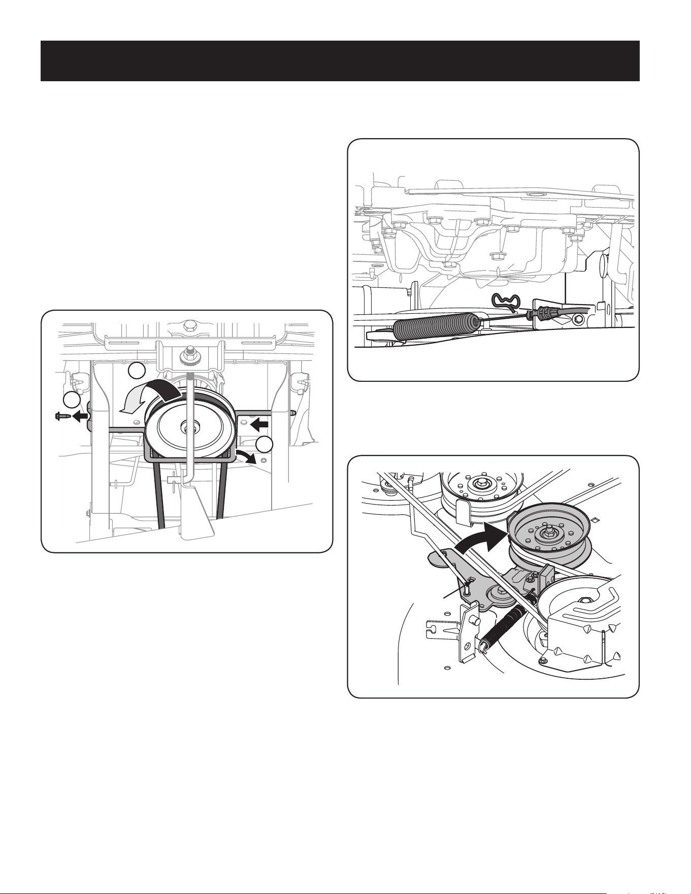
25
SERVICE AND MAINTENANCE
Relays and Switches
There are several safety switches in the electrical system. If a function of the safety
interlock system described earlier is not functioning properly, have the electrical
system checked by your authorized service dealer.
Cutting Deck Removal
42”Decks
1. To remove the cutting deck, proceed as follows:
a. Place the PTO in the disengaged (OFF) position and engage the parking
brake.
b. Lower the deck by moving the deck lift lever into the bottom notch
on the right fender.
c. Remove the hex screw securing the engine pulley keeper rod to the
frame. See Figure 24.
3
4
8
Figure 24
d. Slide the rod to the right to remove it. See Figure 24.
NOTE: Be careful not to damage the wire harness when removing the rod.
e. Remove the bow-tie pin that secures the PTO cable to the bracket on
the deck, pull back on the PTO cable, then slide it out of the bracket
and unhook the spring from the idler bracket. See Figure 25.
Figure 25
f. Working on the right side of the tractor, insert a 3⁄8” drive ratchet
wrench, set to tighten, into square hole found on the idler bracket.
See Figure 26.
Insert Wrench Here
Figure 26
g. Skip ahead to Step 2 on page 27.
46” Decks
1. To remove the cutting deck, proceed as follows:
a. Place the PTO in the disengaged (OFF) position and engage the parking
brake.
b. Lower the deck by moving the deck lift lever into the bottom notch
on the right fender.
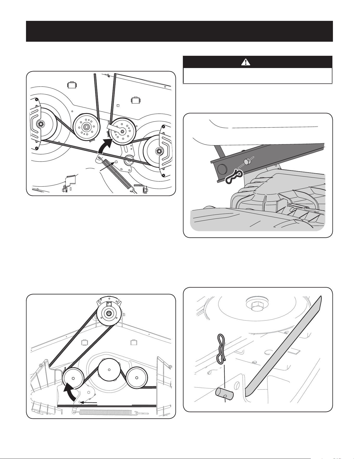
26
SERVICE AND MAINTENANCE
c. Working on the right side of the tractor, insert a 3⁄8” drive ratchet
wrench, set to tighten, into square hole found on the idler bracket.
See Figure 27.
Insert Wrench Here
Figure 27
d. Skip ahead to Step 2 on page 27.
50” & 54” Decks
1. To remove the cutting deck, proceed as follows:
a. Place the PTO in the disengaged (OFF) position and engage the parking
brake.
b. Lower the deck by moving the deck lift lever into the bottom notch
on the right fender.
c. Working on the right side of the tractor, insert a 3⁄8” drive ratchet
wrench, set to tighten, into square hole found on the idler bracket.
See Figure 28.
Insert Wrench Here
Figure 28
d. Continue with Step 2 on page 27.
2. Use the wrench to pivot the deck drive pulley forward. See Figure 28.
WARNING
Avoid pinching injuries. Never place your fingers on the idler spring or
between the belt and a pulley while installing the belt.
3. Carefully remove the belt from around the PTO pulley.
4. Looking at the cutting deck from the right side of the tractor, locate the
bow-tie pin on the rear right side of the deck. See Figure 29.
Figure 29
5. Remove the bow pin and slide the deck pin out of the deck lift arm. See Figure 29.
6. Repeat the above steps on the tractor’s left side.
7. Pull the bow-tie pin out of the front deck lift rod securing it to the deck. See
Figure 30. Slide the deck lift rod out of the front hanger bracket.
Figure 30
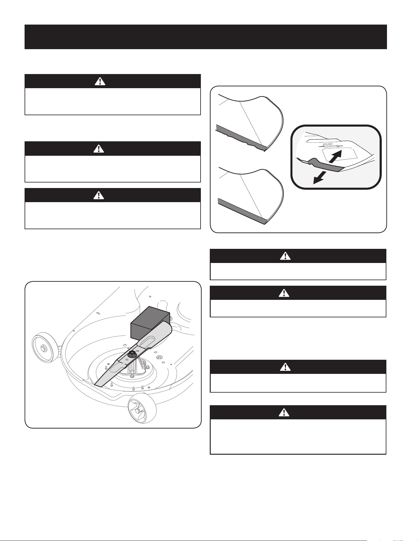
27
SERVICE AND MAINTENANCE
8. Move the deck lift lever into the top notch to raise the deck lift up and out of
the way.
CAUTION
There is a certain amount of spring tension due to the weight of the deck. When
removing the lift linkage from the deck the tension of the springs will go from the
deck to the deck lift handle and snap back.
9. Gently slide the cutting deck out from underneath the tractor.
Cutting Blades
WARNING
Shut the engine off and remove ignition key before removing the cutting
blade(s) for sharpening or replacement. Protect your hands by using heavy
gloves when grasping the blade.
WARNING
Periodically inspect the blade and/or spindle for cracks or damage,
especially after you’ve struck a foreign object. Do not operate the machine
until damaged components are replaced.
To remove the blades, proceed as follows.
1. Remove the deck from beneath the tractor, (refer to Cutting Deck Removal
earlier in this section) then gently flip the deck over to expose its underside.
2. Place a block of wood between the deck housing baffle and the cutting
blade to act as a stabilizer. See Figure 31.
Figure 31
3. Remove the hex flange nut that secures the blade to the spindle assembly.
See Figure 31.
4. To properly sharpen the cutting blades, remove equal amounts of metal
from both ends of the blades along the cutting edges, parallel to the trailing
edge, at a 25°- to 30° angle. Always grind each cutting blade edge equally to
maintain proper blade balance. See Figure 32.
Figure 32
CAUTION
If the cutting edge of the blade has previously been sharpened, or if any
metal separation is present, replace the blades with new ones.
WARNING
A poorly balanced blade will cause excessive vibration, may damage the
tractor and/or result in personal injury.
5. Test the blade’s balance using a blade balancer. Grind metal from the heavy
side until it balances evenly.
NOTE: When replacing the blade, be sure to install the blade with the side of
the blade marked ‘‘Bottom’’ (or with a part number stamped in it) facing the
ground when the mower is in the operating position.
CAUTION
Use a torque wrench to tighten the blade spindle hex flange nut to between
70 ft-lbs and 90 ft-lbs.
Changing the Deck Belt
WARNING
The V-belts found on your tractor are specially designed to engage and
disengage safely. A substitute (non-OEM) V-belt can be dangerous by
not disengaging completely. For a proper working machine, use factory
approved belts.
All belts on your tractor are subject to wear and should be replaced if any signs of wear
are present . To change or replace the deck belt on your tractor, proceed as follows:
1. Remove the deck as instructed earlier in this section under Cutting Deck Removal.
NOTE: On some decks it may be necessary to remove the spindle covers to
remove and/or install the new belt. To remove the spindle covers, remove
the screws securing them to the deck.
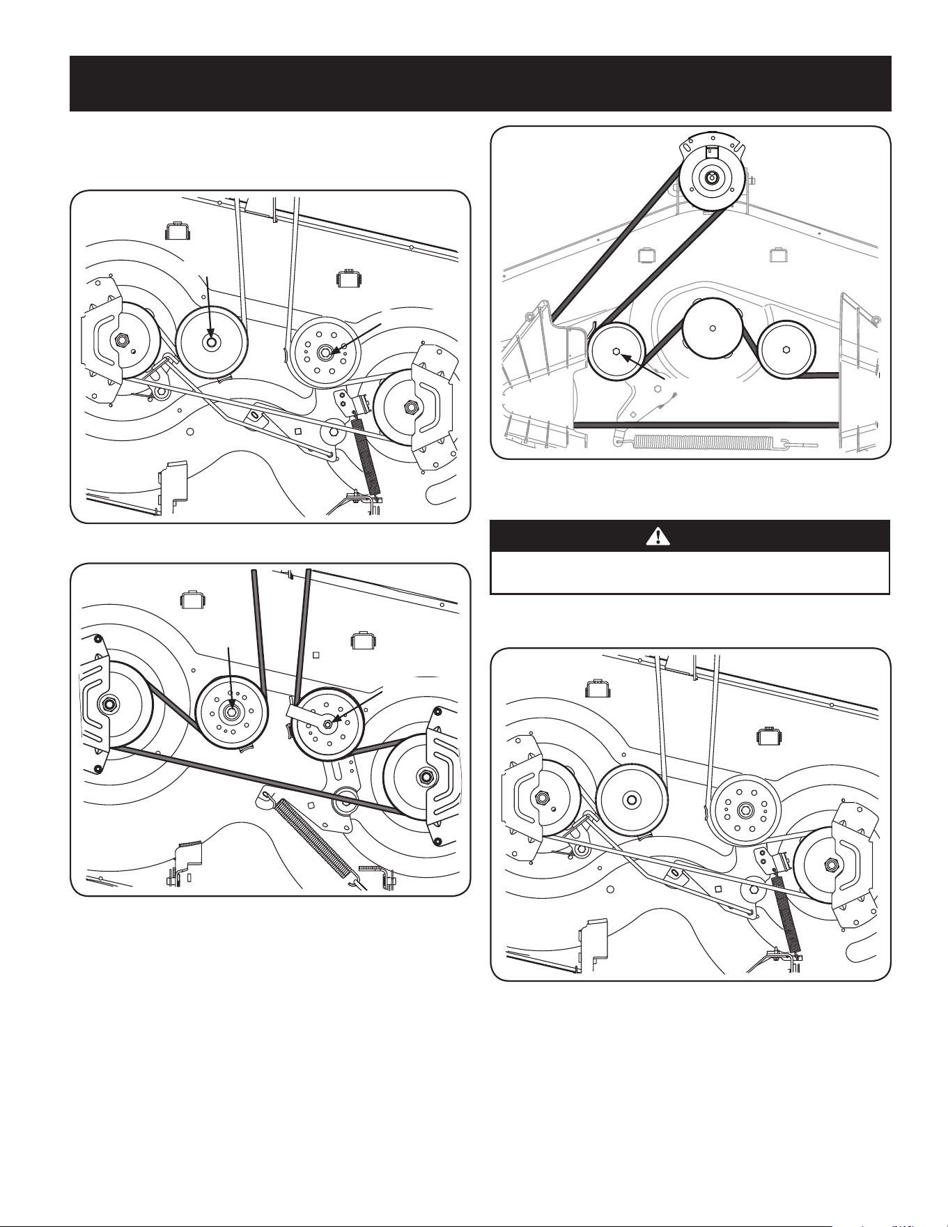
28
SERVICE AND MAINTENANCE
2. Loosen, but do not remove the flange lock nut on the left idler pulley for 50”
and 54” Decks and the right idler pulley for 42” and 46” Decks. See Figure 33
for 42” Decks, Figure 34 for 46” Decks and Figure 35 for 50” and 54” Decks.
Hex Screw
Flange Lock Nut
Figure 33
Hex Screw
Flange Lock Nut
Figure 34
Flange Lock Nut
Figure 35
3. Carefully remove the belt from around the idler pulleys and the spindle pulleys.
WARNING
Avoid pinching injuries. Never place your fingers on the idler spring or
between the belt and a pulley while removing the belt.
4. Route the new belt as shown in Figure 36 for 42” Decks, Figure 37 for 46”
Decks and Figure 38 for 50” and 54” Decks.
Figure 36
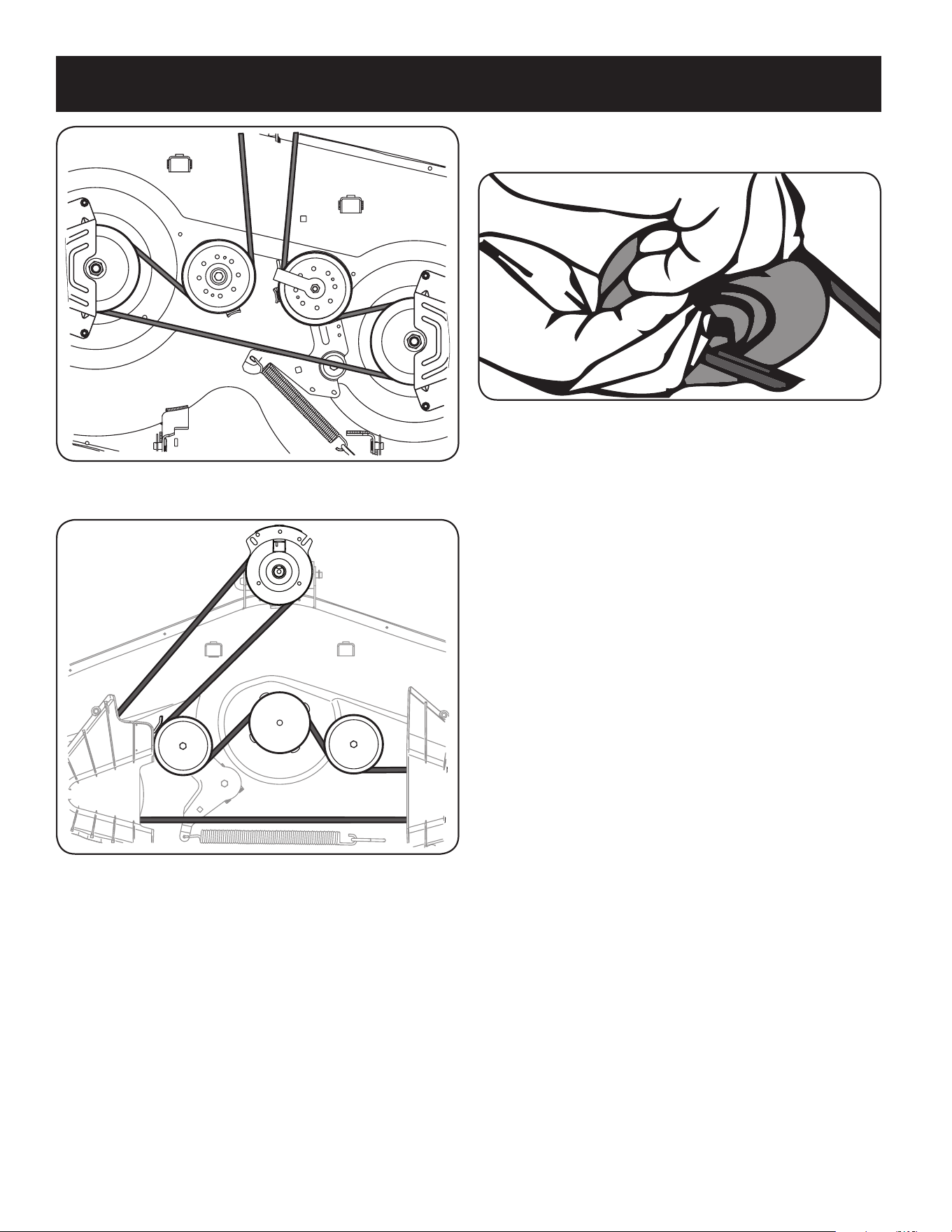
29
SERVICE AND MAINTENANCE
Figure 37
Figure 38
NOTE: Use a 3⁄8” drive ratchet wrench as instructed in earlier steps when
routing the new belt.
5. Retighten idler pulleys.
6. Remount the spindle covers if removed after step 1.
7. Re-install the deck making sure the belt remains routed around the pulleys
as instructed.
8. Pull the right side of the belt and place the narrow V side of the belt into the
PTO pulley. See Figure 39.
Figure 39
9. While holding the belt and pulley together, rotate the pulley to the left.
Continue holding and rotating the pulley and belt until the belt is fully rolled
into the PTO pulley.
Changing the Transmission Drive Belt
Several components must be removed and special tools used in order to change
the tractor’s transmission drive belt. See a qualified service dealer to have the
transmission drive belt replaced.

30
OFF-SEASON STORAGE
WARNING
Gasoline is a toxic substance. Dispose of gasoline properly. Contact
your local authorities for approved disposal methods.
3. Remove the spark plug and pour one (1) ounce of engine oil
through the spark plug hole into the cylinder. Crank the engine
several times to distribute the oil. Replace the spark plug.
4. Clean debris from around engine, under finger guard, and under,
around and behind muffler. Touch up any damaged paint, and
coat other areas that may rust with a light film of oil.
5. Store in a clean, dry and well ventilated area away from any ap-
pliance that operates with a flame or pilot light, such as a furnace,
water heater, or clothes dryer. Also avoid any area with a spark
producing electric motor, or where power tools are operated.
6. If possible, also avoid storage areas with high humidity, because
that promotes rust and corrosion.
7. Keep the engine level in storage. Tilting can cause fuel or oil
leakage.
DRAINING THE FUEL
1. Locate the fuel filter, which is located on the left side of the
engine, and may be attached to the engine with a tie strap.
2. Cut the tie strap, if present, then pinch the in-line clamp on the
fuel filter with a pair of pliers, slide the clamp up the fuel line.
3. Pull the fuel line free from the filter and place the open end of the
line into an approved container to drain the fuel.
PREPARING THE LAWN TRACTOR
1. Clean and lubricate the unit thoroughly as described in the
Lubrication instructions in the Service and Maintenance section.
2. Do not use a pressure washer or garden hose to clean your unit.
3. Store mower in a dry, clean area. Do not store next to corrosive
materials, such as fertilizer.
Removing From Storage
1. Check the oil level as described in the Assembly section of this
manual.
2. If the fuel was drained during storage preparation, fill the tank with
fresh gasoline. If you keep a container of gasoline for refueling,
make certain it contains only fresh fuel. Gasoline oxidizes and
deteriorates over time, causing hard starting.
3. If the cylinder was coated with oil during storage preparation, the
engine will smoke briefly at startup. This is normal.
WARNING
Never store lawn tractor with fuel in tank indoors or in poorly
ventilated areas where fuel fumes may reach an open flame, spark,
or pilot light as on a furnace, water heater, clothes dryer, or gas
appliance.
PREPARING THE ENGINE
IMPORTANT: Fuel left in the fuel tank during warm weather deterio-
rates and will cause serious starting problems.
CAUTION
Failure to use a fuel stabilizing additive or completely run the engine
until it’s out of fuel before off-season storage may result in damage to
your engine’s carburetor. Subsequent damage would not be covered
under the manufacturer’s warranty.
Engines stored between 30 and 90 days need to be treated with a
gasoline stabilizer and engines stored over 90 days need to be drained
of fuel to prevent deterioration and gum from forming in fuel system or
on essential carburetor parts. If the gasoline in your engine deterio-
rates during storage, you may need to have the carburetor, and other
fuel system components, serviced or replaced.
To prevent gum deposits from forming inside the engine’s carburetor
and causing possible malfunction of the engine, the fuel system must
be either completely emptied, or the gasoline must be treated with a
stabilizer to prevent deterioration.
1. If using a fuel stabilizer:
a. Read the product manufacturer’s instructions and recom-
mendations.
b. Add to clean, fresh gasoline the correct amount of stabilizer
for the capacity of the fuel system.
c. Fill the fuel tank with treated fuel and run the engine for 2-3
minutes to get stabilized fuel into the carburetor.
2. If emptying the fuel system:
a. Do not drain fuel when the engine is hot. Allow the engine
adequate time to cool. Drain fuel into an approved container
outdoors, away from open flame.
b. Drain any large volume of fuel from the tank by disconnect-
ing the fuel line from the in-line fuel filter near the engine.
See the complete instructions for Draining The Fuel later in
this section.
WARNING
Gasoline is extremely flammable and can be explosive under certain
conditions. Drain gasoline before storing the equipment for extended
periods. Drain fuel only into an approved container outdoors, away
from an open flame. Allow engine to cool. Extinguish cigarettes,
cigars, pipes, and other sources of ignition prior to draining fuel.
Store gasoline in an approved container in safe location.
c. Reconnect the fuel line and run the engine until it starts to
falter, then use the choke to keep the engine running until all
fuel in the carburetor has been exhausted.
d. Disconnect the fuel line and drain any remaining gasoline
from the system.

31
TROUBLESHOOTING
This section addresses minor service issues. To locate the nearest authorized Service Center or to schedule service, call 1-888-331-4569.
WARNING
Before performing any type of maintenance/service, disengage all controls and stop the engine. Wait until all moving parts have come to a complete
stop. Disconnect spark plug wire and ground it against the engine to prevent unintended starting. Always wear safety glasses during operation or while
performing any adjustments or repairs.
Problem Cause Remedy
Engine fails to start 1. PTO/Blade Engage knob engaged.
2. Parking brake not engaged.
3. Spark plug wire disconnected.
4. Throttle control lever not in correct starting
position.
5. Fuel tank empty, or stale fuel.
6. Blocked fuel line.
7. Faulty spark plug.
8. Engine flooded.
9. Fuse(s) blown.
1. Place knob in disengaged (OFF) position.
2. Engage parking brake.
3. Connect wire to spark plug.
4. Place Throttle lever to FAST position.
5. Fill tank with clean, fresh (less than 30 days old) gas.
6. Replace fuel line. See a qualified service dealer.
Replace fuel filter. See the Service and Maintenance
section.
7. Clean, adjust gap or replace plug.
8. Crank engine with throttle in FAST position.
9. Replace fuse.
Engine runs erratically 1. Tractor running with Choke activated.
2. Spark plug wires loose.
3. Blocked fuel line or stale fuel.
4. Vent in gas cap plugged.
5. Water or dirt in fuel system.
6. Dirty air cleaner.
1. Check that the electric choke is working. See a
qualified service dealer.
2. Connect and tighten spark plug wires.
3. Replace fuel line. See a qualified service dealer. Fill
tank with clean, fresh gasoline and replace fuel filter.
See the Service and Maintenance section.
4. Clear vent or replace cap if damaged.
5. Drain fuel tank. Refill with clean, fresh gasoline. See
the Service and Maintenance section.
6. Clean or replace air cleaner paper element or clean
foam pre-cleaner.
Engine overheats 1. Engine oil level low
2. Air flow restricted
1. Fill engine with proper amount and type of oil.
2. Clean grass clippings and debris from around the
engine’s cooling fins and blower housing.
Engine hesitates at high RPMs 1. Spark plug gap set too close 1. Remove spark plug and adjust gap.
Engine idles poorly 1. Fouled spark plug
2. Dirty air cleaner
1. Replace spark plug and adjust gap.
2. Clean or replace air cleaner element and/or clean
pre-cleaner.
Excessive vibration 1. Cutting blades loose or unbalanced
2. Damaged, dull, or bent cutting blade
1. Tighten blade and spindle. Balance blade.
2. Replace blade.
Mower will not mulch grass 1. Engine speed too low.
2. Wet grass.
3. Excessively high grass.
4. Dull blade.
1. Place Throttle control in FAST (rabbit) position.
2. Do not mulch when grass is wet.
3. Mow once at a high cutting height, then mow again
at desired height or make a narrower cutting swath.
4. Sharpen or replace blade.
Uneven cut 1. Deck not leveled properly.
2. Dull blade.
3. Uneven tire pressure.
1. Perform side-to-side deck adjustment.
2. Sharpen or replace blade.
3. Check tire pressure in all four tires.

NOTES
25

33
ÍNDICE
NÚMERO DE MODELOESPECIFICACIONES DEL PRODUCTO
Medidas de seguridad .........................Página 34
Montaje ......................................Página 40
Operación ....................................Página 44
Servicio y Mantenimiento .....................Página 50
Almacenamiento fuera de temporada .........Página 61
Solución de problemas ........................Página 62
Declaración de garantía ..............Vea el suplemento
seperado
Motor: Consulte el manual del motor
Aceite del motor: Consulte el manual del motor
Capacidad del aceite: Consulte el manual del motor
Combustible: Gasolina sin plomo
Número de modelo _____________________________
Número de serie ________________________________
Fecha de compra _______________________________
Registre el número de modelo, número de serie y fecha
de compra más arriba.

34
INSTRUCCIONES DE SEGURIDAD
FUNCIONAMIENTO GENERAL
• Lea, entienda y cumpla todas las instrucciones incluidas en la máquina y en el(los)
manual(es) antes de intentar realizar el montaje de la unidad y utilizarla. Guarde
este manual en un lugar seguro para consultas futuras y periódicas, así como para
solicitar repuestos.
• Familiarícese con todos los controles y con el uso adecuado de los mismos.
Sepa cómo detener la máquina y desactivar los controles rápidamente.
• No permita nunca que los niños menores de 14 años utilicen esta máquina.
Los niños de 14 años y mayores deben leer y comprender las instrucciones de
operación y las reglas de seguridad contenidas en este manual, y también
deben ser capacitados y estar supervisados por uno de los padres.
• Nunca permita que los adultos operen esta máquina sin recibir antes la
instrucción apropiada.
• Para tratar de evitar el contacto con las cuchillas o una lesión por algún objeto
que sea arrojado, mantenga a los observadores, a los ayudantes, niños y mascotas
alejados al menos 25 metros de la máquina mientras está en funcionamiento.
Detenga la máquina si alguien se acerca.
• Inspeccione minuciosamente el área donde utilizará el equipo. Saque todas las
piedras, palos, cables, huesos, juguetes y demás objetos extraños que podrían
ser levantados y arrojados por las cuchillas. Los objetos arrojados por la máquina
pueden causar lesiones graves.
• Planifique el patrón de corte, para evitar que la descarga de material se realice
hacia los caminos, las veredas, los observadores, etc. Evite además descargar
material contra una pared u obstrucción, ya que esto podría hacer que el material
descargado rebotara contra el operador.
• Para protegerse los ojos utilice siempre anteojos o antiparras de seguridad
mientras opera la máquina o mientras le hace ajustes o reparaciones. Los objetos
arrojados que rebotan pueden causar lesiones graves en los ojos.
• Utilice zapatos de trabajo resistentes, de suela fuerte, así como pantalones y
camisas ajustados. Las prendas sueltas y las alhajas pueden quedar atrapadas en
las piezas móviles. Nunca haga funcionar la máquina descalzo o con sandalias.
• Para un uso prolongado de este producto, se requiere protección auditiva.
• Esté atento a la dirección de descarga del tractor cortacésped y sus accesorios y
no los apunte a nadie. No haga funcionar el tractor cortacésped sin que la tapa de
descarga o todo el colector de césped se encuentre en el lugar que corresponde.
• No coloque las manos ni los pies cerca de piezas que giran ni debajo de la
plataforma de corte. El contacto con las cuchillas puede amputar manos y pies.
• Una cubierta de descarga faltante o dañada puede provocar lesiones por contacto
con la cuchilla o por objetos arrojados.
• Detenga las cuchillas al cruzar sendas, senderos o caminos de grava y cuando no
corte césped.
• Tenga cuidado con el tráfico cuando opere cerca de rutas o cruzándolas. Esta
máquina no está diseñada para ser usada en la vía pública.
• No haga funcionar la máquinas si se encuentra bajo los efectos del alcohol o
las drogas.
• Úsela solamente con luz natural o con buena luz artificial.
• Nunca lleve pasajeros.
• Desacople las cuchillas antes de cambiar a marcha atrás. Retroceda lentamente
Siempre mire hacia abajo y hacia atrás antes y mientras retrocede para evitar
un accidente.
• Reduzca la velocidad antes de girar. Haga funcionar la máquina de manera
uniforme. Evite que funcione de manera errática y a excesiva velocidad.
• Desacople las cuchillas, ponga el freno de mano, apague el motor y espere hasta
que las cuchillas se detengan por completo antes de retirar el colector de césped,
vaciar los recortes, destapar el canal, retirar restos de césped o desechos, o hacer
cualquier ajuste.
• Nunca deje la máquina en funcionamiento sin vigilancia. Siempre apague
las cuchillas, ponga el freno de mano, pare el motor y retire la llave antes
de desmontar.
• Tenga mucho cuidado al cargar o descargar la máquina en un remolque o camión.
Esta máquina no debe conducirse subiendo o bajando rampas, ya que la máquina
podría volcar y provocar lesiones personales graves. La máquina se debe empujar a
mano en rampas para cargarla o descargarla correctamente.
ADVERTENCIA
La presencia de este símbolo indica que se trata de instrucciones de seguridad
importantes que debe respetar para evitar poner en riesgo su seguridad
personal y/o material y la de los demás. Lea y cumpla todas las instrucciones
de este manual antes de intentar operar esta máquina. Si no respeta estas
instrucciones puede provocar lesiones personales. Cuando vea este símbolo,
¡TENGA EN CUENTA LA ADVERTENCIA!
ADVERTENCIA
PROPOSICIÓN 65 DE CALIFORNIA
El escape del motor, algunos de los elementos del mismo y algunos componentes
del vehículo contienen o liberan sustancias químicas que según el Estado de
California pueden producir cáncer, defectos de nacimiento u otros problemas
reproductivos.
Los bornes, los terminales y los accesorios relacionados de la batería contienen
plomo y compuestos de plomo, sustancias químicas que según lo establecido por
el Estado de California causan cáncer y daños en el sistema reproductivo. Lávese
las manos después de estar en contacto con estos componentes.
PELIGRO
Esta máquina está diseñada para ser utilizada respetando las normas de
seguridad contenidas en este manual. Al igual que con cualquier tipo de equipo
motorizado, un descuido o error por parte del operador puede producir lesiones
graves. Esta máquina es capaz de amputar dedos, manos y pies y de arrojar
residuos. De no respetar las instrucciones de seguridad siguientes se pueden
ocasionar lesiones graves o la muerte.
ADVERTENCIA
Su responsabilidad—Limite el uso de esta máquina motorizada a las
personas que lean, comprendan y cumplan las advertencias e instrucciones que
aparecen en este manual y en la máquina.
¡GUARDE ESTAS INSTRUCCIONES!

35
INSTRUCCIONES DE SEGURIDAD
• El silenciador y el motor se calientan y pueden causar quemaduras. No los toque.
• Revise la holgura superior antes de conducir debajo de ramas bajas, cables,
cerramientos de puertas, etc., donde el operador puede golpearse o ser tirado
de la máquina, lo que podría resultar en lesiones graves.
• Desactive todos los embragues de los accesorios y oprima a fondo el pedal del
freno antes de intentar arrancar el motor.
• Su máquina está diseñada para cortar césped residencial normal de una altura
no mayor a 10 pulgadas. No intente cortar césped demasiado crecido, seco (por
ejemplo, pastura) ni pilas de hojas secas. El césped o las hojas secas pueden
ponerse en contacto con el escape del motor y/o acumularse en la plataforma de
corte constituyendo un peligro de incendio en potencia.
• Utilice solamente accesorios y complementos aprobados por el fabricante para
esta máquina. Lea, comprenda y siga todas las instrucciones incluidas con el
accesorio o complemento aprobado. Para obtener una lista de los dispositivos de
sujeción o accesorios aprobados, llame al 1-888-331-4569.
• Los datos indican que los operadores mayores de 60 años participan de un gran
porcentaje de lesiones relacionadas con tractores cortacésped. Estas personas
deben evaluar su capacidad para operar el tractor de manera suficientemente
segura para protegerse a sí mismos y a otros de lesiones graves.
• Si se presentan situaciones que no están previstas en este manual, tenga cuidado y
use el sentido común.
FUNCIONAMIENTO EN PENDIENTES
Las pendientes son un factor importante relacionado con accidentes por pérdida de
control y vuelcos que pueden producir lesiones graves o la muerte. Todas las pendientes
requieren mayor precaución. Si no puede retroceder por la pendiente o si no se siente
seguro, no realice ningún corte.
Para su seguridad, use la Guía para la operación en pendientes que se adjunta a este
manual para medir la pendiente antes de operar la máquina en una zona inclinada. Si la
pendiente es de más de 15º, como se muestra en la Guía para la operación en pendientes,
no haga funcionar esta máquina en ese sector o podría causar lesiones graves.
Haga lo siguiente:
• Corte en las pendientes hacia arriba y hacia abajo, no de manera transversal.
Tenga mucho cuidado al cambiar de dirección en una pendiente.
• Esté atento a los hoyos, surcos, baches, rocas u otros objetos ocultos. El terreno
desnivelado puede voltear la máquina. El césped alto puede ocultar obstáculos.
• Conduzca a baja velocidad. Seleccione una velocidad lo suficientemente baja como
para que no necesite detenerse o cambiar de marcha estando en pendiente. Los
neumáticos pueden perder tracción sobre las pendientes aún cuando los frenos
funcionaran correctamente. Siempre mantenga la máquina en cambio mientras
desciende una pendiente para poder frenar con el motor.
• Siga las recomendaciones del fabricante sobre los pesos o contrapesos de las
ruedas para mejorar la estabilidad.
• Tenga mucho cuidado con los colectores de césped y otros complementos. Pueden
modificar la estabilidad de la máquina.
• Todos los movimientos en las pendientes deben ser lentos y graduales. No
haga cambios bruscos de velocidad o dirección. Hacer un cambio o frenar
repentinamente pueden hacer que el frente de la máquina se levante y voltee
hacia atrás rápidamente lo que podría producir lesiones graves.
• Evite arrancar y detenerse cuando está en una pendiente. Si las ruedas pierden
tracción, desacople las cuchillas y descienda la pendiente lentamente.
No haga lo siguiente:
• No gire en pendiente a menos que sea necesario; si lo hace, gire lenta y
gradualmente cuesta abajo, si es posible.
• No corte cerca de caídas, zanjas o terraplenes. La cortadora puede volcarse
repentinamente si una de las ruedas pasa el borde de un acantilado o zanja,
o si se desmorona un borde.
• No intente estabilizar la máquina poniendo un pie en tierra.
• No utilice el recolector en pendientes pronunciadas.
• No recorte el césped mojado. La falta de tracción puede hacer que se deslice.
• No intente bajar por inercia. El exceso de velocidad puede hacer que el operador
pierda el control de la máquina y se produzcan lesiones graves o la muerte.
• No remolque complementos de arrastrar pesados (como carrito de basura cargado,
podadora de rodillos, etc.) en pendientes de más de 5º. Cuando se desplaza cuesta
abajo, el peso adicional tiende a empujar el tractor y puede hacerle perder el
control (por ejemplo, el tractor se puede acelerar, la capacidad de conducir y frenar
se reducen, el complemento puede acodillarse y hacer que el tractor vuelque).
NIÑOS
Pueden ocurrir accidentes trágicos si el operador no está atento a la presencia de niños.
Por lo general, los niños se sienten atraídos por la máquina y su actividad. No entienden
los riesgos ni los peligros. Nunca suponga que los niños permanecerán en el lugar donde
los vio por última vez.
• Mantenga a los niños fuera del área de corte y bajo estricta vigilancia de un adulto
responsable además del operador.
• Esté alerta y apague la máquina si un niño ingresa al área.
• Antes de moverse hacia atrás y mientras lo hace, mire hacia atrás y abajo viendo
que no haya niños.
• Nunca transporte niños, ni siquiera con las cuchillas desactivadas. Podrían caerse y
resultar gravemente heridos o interferir con la operación segura de la máquina.
• Tenga extrema precaución cuando se aproxime a esquinas ciegas, portales,
arbustos, árboles u otros objetos que puedan impedirle ver a un niño que pueda
chocar con la máquina.
• Para evitar accidentes retrocediendo, siempre desacople las cuchillas antes
de cambiar a marcha atrás. Si está equipado, el “Modo de marcha atrás con
precaución” (en el que las cuchillas funcionan mientras la máquina se desplaza
marcha atrás) no se debe usar cuando hay niños y otras personas alrededor.
• Mantenga a los niños alejados de los motores en marcha o calientes. Pueden
sufrir quemaduras con un silenciador caliente.
• Retire la llave cuando la máquina queda sin vigilancia para evitar el
funcionamiento no autorizado.
No permita nunca que los niños menores de 14 años utilicen esta máquina. Los niños
de 14 años en adelante deben leer y entender las instrucciones de funcionamiento y las
normas de seguridad contenidas en este manual y en la máquina y deben ser entrenados y
supervisados por un adulto.
REMOLQUE
• Remolque únicamente con una máquina que tenga un enganche diseñado para
remolcar. No acople equipo remolcado excepto en el punto de enganche.
• Siga las recomendaciones del fabricante en lo que respecta a los límites de peso
de los equipos a remolcar y al remolque en pendientes.
• Nunca permita que los niños y otras personas se suban a equipos remolcados.

36
INSTRUCCIONES DE SEGURIDAD
• En las pendientes, el peso del equipo remolcado puede causar pérdida de tracción
y pérdida de control.
• Siempre tenga mucho cuidado al remolcar con una máquina capaz de hacer giros
cerrados (por ejemplo, tractor cortacésped con radio de giro cero). Realice giros
amplios para el acodillamiento.
• Desplácese lentamente y deje distancia adicional para detenerse.
• No baje las pendientes por inercia.
SERVICIO
Manejo seguro de la gasolina:
Para evitar lesiones personales o daños materiales tenga mucho cuidado al
manipular la gasolina. La gasolina es sumamente inflamable y sus vapores
pueden causar explosiones. Si se derrama gasolina encima o sobre la ropa se
puede lesionar gravemente ya que se puede encender. Lávese la piel y cámbiese
de ropa de inmediato.
• Utilice sólo los recipientes para gasolina autorizados.
• Nunca llene los recipientes dentro de un vehículo o un camión o un remolque
con recubrimiento plástico. Coloque siempre los recipientes en el piso y lejos del
vehículo antes de llenarlo.
• Cuando sea conveniente, retire el equipo a gasolina del camión o remolque y
llénelo sobre el suelo. Si esto no es posible, llene el equipo en un remolque con un
recipiente portátil, en vez de hacerlo desde una boquilla dispensadora de gasolina.
• En todo momento mantenga la boquilla en contacto con el borde del depósito de
combustible o con la abertura del recipiente, hasta terminar la carga. No utilice un
dispositivo de apertura/cierre de la boquilla,
• Apague todos los cigarrillos, cigarros, pipas y otras fuentes de combustión.
• Nunca cargue combustible en la máquina en un espacio cerrado.
• Nunca saque la tapa del combustible ni agregue combustible mientras el motor
está caliente o en marcha. Deje que el motor se enfríe por lo menos dos minutos
antes de volver a cargar combustible.
• Nunca llene en exceso el depósito de combustible. Llene el depósito no más de
½ pulgada por debajo de la base del cuello de llenado para dejar espacio para la
expansión del combustible.
• Vuelva a colocar el tapón de combustible y ajústelo bien.
• Limpie el combustible que se haya derramado sobre el motor y el equipo. Traslade
la máquina a otra zona. Espere 5 minutos antes de encender el motor.
• Para reducir el riesgo de incendio, mantenga la máquina limpia de pasto, hojas y
residuos acumulados. Limpie los derrames de aceite o combustible y saque todos
los residuos embebidos en combustible.
• Nunca guarde la máquina o el recipiente de combustible en un espacio cerrado
donde haya fuego, chispas o luz piloto, como por ejemplo de calentadores de agua,
calefactores de ambientes, hornos, secadores de ropa u otros aparatos a gas.
• Deje que la máquina se enfríe por lo menos cinco minutos antes de guardarla.
Servicio general
• Nunca encienda el motor en espacios cerrados o en una zona con poca ventilación.
El escape del motor contiene monóxido de carbono, un gas inodoro y letal.
• Antes de limpiar, reparar o inspeccionar la máquina, compruebe que las
cuchillas y todas las piezas móviles se hayan detenido. Desconecte el cable de
la bujía y póngalo haciendo masa contra el motor para evitar que se encienda
accidentalmente.
• Controle periódicamente para asegurarse que las cuchillas se detienen
completamente aproximadamente cinco (5) segundos después de accionar el
control de desacople. Si las cuchillas no se detienen dentro de este lapso, su
máquina debe ser reparada por un profesional de servicio calificado.
• Controle el funcionamiento de los frenos con frecuencia, ya que está sujeto
a desgaste durante el funcionamiento normal. Realice los ajustes y el
mantenimiento necesario.
• Controle las cuchillas y los pernos de montaje del motor a intervalos frecuentes
para verificar que estén bien apretados. Además, inspeccione visualmente las
cuchillas buscando daño (por ejemplo: desgaste excesivo, abolladuras, rajaduras).
Reemplace las cuchillas únicamente por cuchillas de los fabricantes del equipo
original (O.E.M.) listados en este manual. El uso de piezas que no cumplen con las
especificaciones del equipo original puede resultar en rendimiento inadecuado y
puede poner en peligro la seguridad.
• Las cuchillas de la cortadora son filosas. Envuelva la cuchilla o utilice guantes y
extreme las precauciones cuando les haga mantenimiento.
• Mantenga todos los pernos, tuercas y tornillos bien ajustados para asegurarse de
que la máquina se encuentra en condiciones seguras de funcionamiento.
• Nunca altere el sistema de bloqueo de seguridad u otros dispositivos de seguridad.
Controle periódicamente que funcionen correctamente.
• Después de golpear algún objeto extraño, detenga el motor, desconecte los
cables de la bujía y conéctelo a tierra con el motor. Inspeccione minuciosamente
la máquina para ver si está dañada. Repare el daño antes de volver a arrancar y
operar la máquina.
• Nunca intente hacer ajustes o arreglos con el motor en marcha.
• Los componentes del recolector de césped y la cubierta de descarga están sujetos
a desgaste y daños lo que podría dejar expuestas las piezas móviles o permitir
que arroje objetos. Para proteger su seguridad, verifique frecuentemente todos
los componentes y reemplácelos inmediatamente sólo por repuestos de los
fabricantes del equipo original (O.E.M.) listados en este manual. El uso de piezas
que no cumplen con las especificaciones del equipo original puede resultar en
rendimiento inadecuado y puede poner en peligro la seguridad.
• No cambie la configuración del regulador del motor ni acelere demasiado el motor.
El regulador del motor controla la velocidad máxima de funcionamiento seguro
del motor.
• Mantenga o reemplace las etiquetas de seguridad y de instrucciones según
sea necesario.
• Observe las leyes y reglamentos sobre la correcta disposición del gas, el petróleo,
etc., para proteger el medio ambiente.
• De acuerdo con la Comisión de Seguridad de los Productos de Consumo de los
Estados Unidos (CPSC) y la Agencia de Protección Ambiental de los Estados Unidos
(EPA), este producto tiene una vida útil estimada de siete (7) años, en condiciones
de uso normales. Al final de su vida útil, haga inspeccionar el producto anualmente
para asegurarse de que todos los sistemas mecánicos y de seguridad funcionen
correctamente, de manera segura y no se usen excesivamente. De lo contrario,
puede provocar un accidente, lesión o muerte.
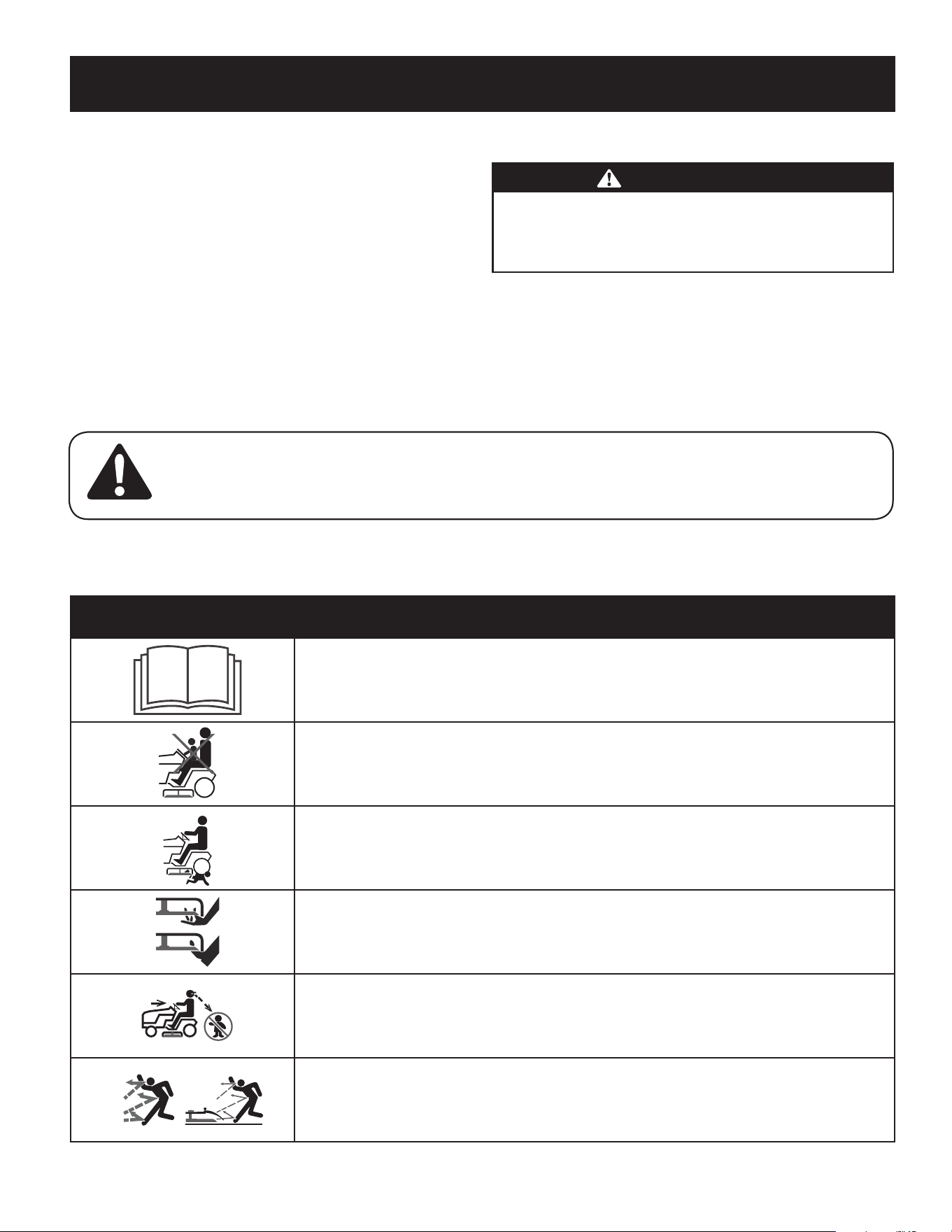
37
INSTRUCCIONES DE SEGURIDAD
NO MODIFIQUE EL MOTOR
Para evitar lesiones graves o la muerte, no modifique el motor de ninguna manera.
Si altera la configuración del regulador, el motor se puede desbocar y funcionar
a velocidades que no son seguras. Nunca cambie la configuración de fábrica del
regulador del motor.
AVISO REFERIDO A EMISIONES
Los motores que están certificados y cumplen con las normas sobre emisiones
federales EPA y de California para SORE (Equipos pequeños todo terreno) están
certificados para funcionar con gasolina sin plomo común y pueden incluir
los siguientes sistemas de control de emisiones: Modificación de motor (EM),
catalizador oxidante (OC), inyección de aire secundaria (SAI) y catalizador de tres
vías (TWC) si están instalados.
ADVERTENCIA: Su responsabilidad—Limite el uso de esta máquina motorizada a las personas que lean, comprendan y
respeten las advertencias e instrucciones que figuran en este manual y en la máquina.
¡GUARDE ESTAS INSTRUCCIONES!
AMORTIGUADOR DE CHISPAS
ADVERTENCIA
Esta máquina está equipada con un motor de combustión interna y no debe
utilizarse en o cerca de un terreno agreste cubierto de bosque, malezas o pasto
a menos que el sistema de escape del motor esté equipado con un amortiguador
de chispas que cumpla con las leyes locales o estatales vigentes (si las hay).
Si se utiliza un amortiguador de chispas el operador lo debe mantener
en condiciones de uso adecuadas. En el Estado de California las medidas
anteriormente mencionadas son exigidas por ley (Artículo 4442 del
Código de Recursos Públicos de California). Es posible que existan leyes
similares en otros estados. Las leyes federales se aplican en territorios
federales. Un supresor de chispas para el silenciador está disponible por
un centro de servicio y reparación de centro de servicio , o llamando al
1-888-331-4569.
SÍMBOLOS DE SEGURIDAD
En esta página se presentan y describen los símbolos de seguridad que en este producto puede tener. Lea, entienda y siga todas las instrucciones incluidas en la máquina
antes de intentar armarla y hacerla funcionar.
Símbolo Descripción
LEA LOS MANUALES DEL OPERADOR
Lea, entienda y siga todas las instrucciones incluidas en los manuales antes de intentar armar la
unidad y hacerla funcionar
PELIGRO — CUCHILLAS GIRATORIAS
Nunca lleve pasajeros. Nunca transporte niños, ni siquiera después de haber desconectado
las cuchillas.
PELIGRO — CUCHILLAS GIRATORIAS
Se recomienda no cortar marcha atrás.
PELIGRO — CUCHILLAS GIRATORIAS
No coloque las manos ni los pies cerca de piezas que giran ni debajo de la plataforma de corte.
El contacto con la(s) cuchilla(s) puede resultar en la amputación de una mano o de un pie.
PELIGRO — CUCHILLAS GIRATORIAS
Siempre mire hacia abajo y hacia atrás antes y mientras se desplaza marcha atrás, para evitar
un accidente.
ADVERTENCIA - OBJETOS LANZADOS
Esta máquina puede recoger y lanzar objetos que pueden causar lesiones personales graves.

38
INSTRUCCIONES DE SEGURIDAD
Símbolo Descripción
PELIGRO — DISPOSITIVOS DE SEGURIDAD
Mantenga los dispositivos de seguridad (guardas, protectores, interruptores, etc.) en su lugar
y funcionando.
OBSERVADORES
Mantenga a los observadores, ayudantes, mascotas y niños por lo menos a 75 pies (23 m.) de la
máquina mientras está en funcionamiento.
ADVERTENCIA — OPERACIÓN EN PENDIENTES
No utilice esta máquina en una pendiente mayor de 15º. No corte en sentido transversal a la
pendiente. Corte hacia arriba y hacia abajo en las pendientes no mayores de 15º. Evite realizar giros
abruptos. Conduzca a baja velocidad. Si la máquina se para mientras sube la pendiente, detenga las
cuchillas y retroceda lentamente hacia abajo.
ADVERTENCIA— SUPERFICIE CALIENTE
Las piezas del motor, especialmente el silenciador, se recalientan durante la operación. Deje que el
motor y el silenciador se enfríen antes de tocarlos.
PELIGRO — CUCHILLAS GIRATORIAS
Para reducir el riesgo de lesiones, mantenga alejados manos y pies. No haga funcionar sin que la tapa
de descarga o el colector de césped se encuentren en el lugar que corresponde. Si están dañados,
reemplácelos inmediatamente.
ADVERTENCIA — RIESGO DE INCENDIO
Deje que la máquina se enfríe antes de cargar combustible o almacenarla.
max10"
ADVERTENCIA — RIESGO DE INCENDIO
No conduzca sobre pilas de hojas secas o pasto alto. Mantenga la máquina libre de residuos.
ADVERTENCIA — RIESGO DE INCENDIO
El funcionamiento de este equipo puede crear chispas que pueden iniciar incendios alrededor de
vegetación seca. Puede requerirse un amortiguador de chispas. El operador debe comunicarse
con las agencias locales de prevención de incendios para conocer las leyes y normativas relativas a
los requerimientos para la prevención de incendios. No permita que se acumulen los residuos. La
acumulación de desechos puede dar lugar a un incendio
10 Máx.
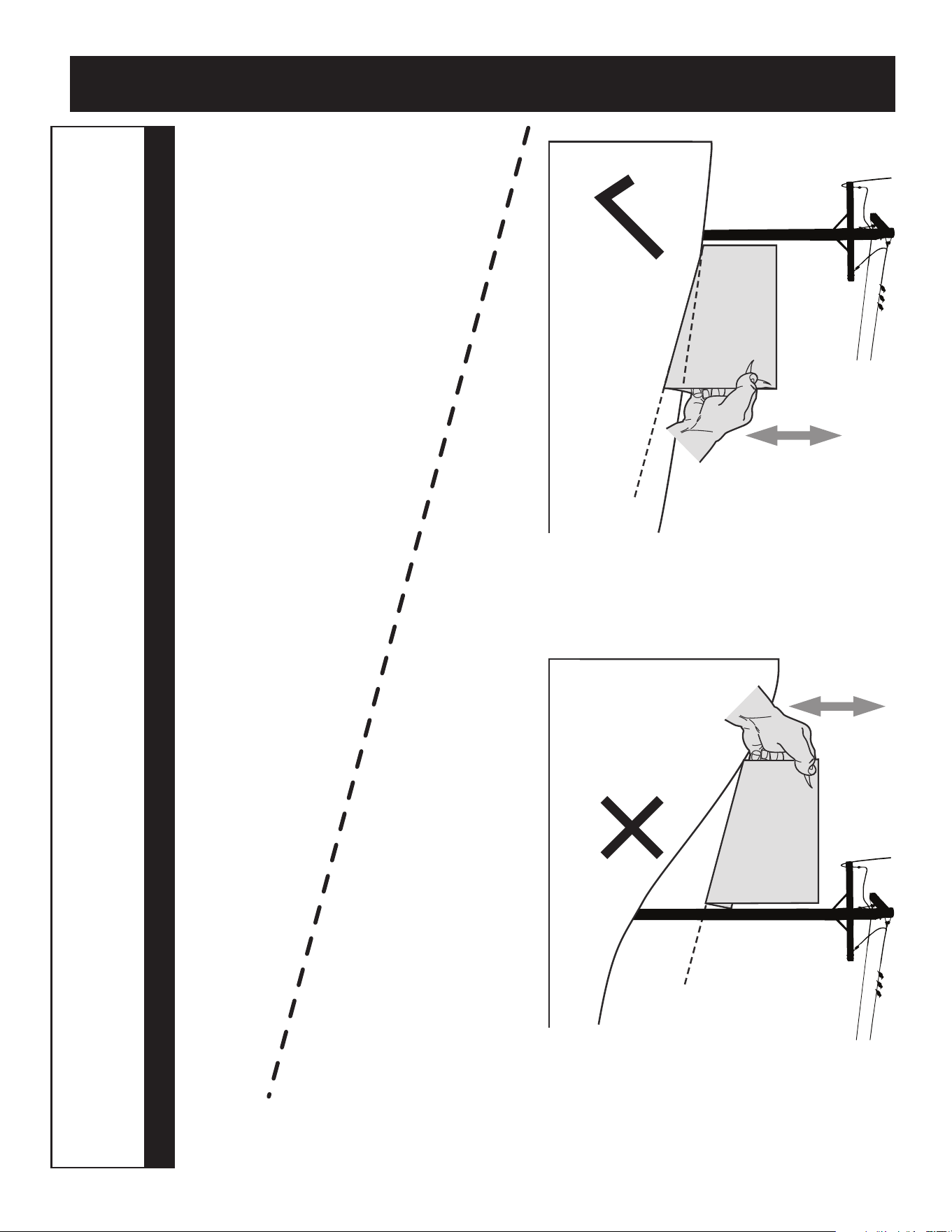
39
INDICADOR DE PENDIENTE
(ACEPTAR) (DEMASIADO ESCARPADO)
USO DE ESTE PENDIENTE DE CALIBRE PARA DETERMINAR
SI UNA PENDIENTE ES DEMASIADO ESCARPADO PARA UNA OPERACIÓN SEGURA!
Para comprobar la pendiente, haga lo siguiente:
1. Borrar esta página y doble a lo largo de la línea discontinua.
2. Localizar un objeto vertical sobre o detrás de la pendiente (un poste, un edificio, una valla, un árbol, etc.)
3. Alinee cada lado de pendiente de calibre con el objeto vertical (consultar Figura 1 and Figura 2 ).
4. Ajuste el pendiente de calibre arriba o hacia abajo hasta los toques esquina izquierda el pendiente
(consultar Figura 1 and Figura 2).
5. Si hay un espacio por debajo de la pendiente de calibre, el pendiente es demasiado escarpa por operación
segura (consultar Figura 2 above).
15° línea discontinua
Figura 2Figura 1
15° Pendiente
15° Pendiente
ADVERTENCIA
Las pendientes son un factor importante relacionado con accidentes por tumbos y vuelcos que pueden producir lesiones graves
o la muerte. No utilice la máquina en pendientes de más de 15°. Todas las pendientes requieren mayor precaución. Si no puede
retroceder por la pendiente o si no se siente seguro, no realice ningún corte. Corte siempre el césped cuesta arriba o cuesta abajo de la
pendiente, nunca en sentido transversal al frente de la pendiente.
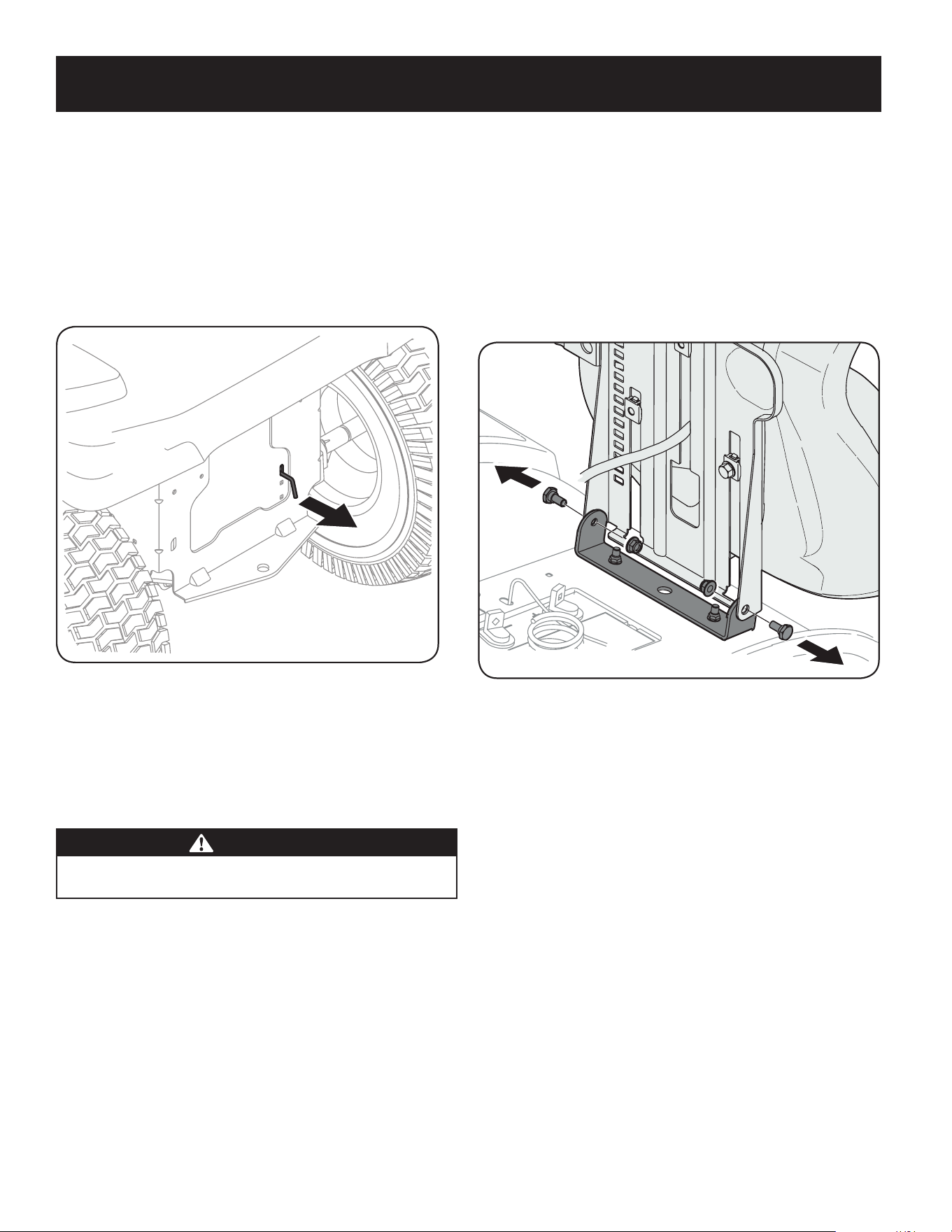
40
MONTAJE
NOTA: Las referencias que contiene este manual sobre los lados derecho o izquierdo
y trasero o delantero del tractor se hacen siempre desde la posición de operación. Las
excepciones, si las hubiere, serán especificadas.
Preparación del tractor
Movimiento manual del tractor
1. Acople las varillas de derivación de la transmisión para mover el tractor
manualmente sin ponerlo en marcha. Las varillas de derivación de la transmisión
están ubicadas en la parte trasera del tractor, sobre el chasis. Acople la varilla de
derivación tirando hacia afuera. Vea la Figura 1.
Figura 1
NOTA: Si el tractor no se mueve o no se mueve libremente al empujarlo compruebe
si la palanca de derivación está completamente abierta o si el freno está activado.
NOTA: La transmisión NO se engancha cuando la varilla de derivación hidrostática
se tira hacia fuera. Regrese la varilla a su posición normal antes de operar el
tractor. Si el tractor no se mueve al presionar sobre los pedales de avance/
retroceso, o se mueve lentamente, compruebe que la válvula de derivación
está activa.
PRECAUCIÓN
Nunca remolque su tractor. Si se remolca el tractor con las ruedas traseras
apoyadas en el suelo se pueden causar daños graves a las transmisiones.
2. Después de mover el tractor, desacople la varilla de derivación empujando la
varilla hacia adentro. Vea la Figura 1.
Instale el asiento del operador (si corresponde)
Para instalar el asiento proceda de la siguiente manera:
NOTA: El asiento se envía con el interruptor de asiento y el contenedor del
asiento acoplados.
1. Corte cualquier tira que sujete el conjunto del asiento al tractor. Quite cualquier
material de empaque.
NOTA: Tenga cuidado para no cortar el cableado que conecta el asiento al
interruptor del asiento.
2. Quite los dos tornillos con reborde y las tuercas de seguridad con brida del
contenedor del asiento tal como se muestra en la Fig. 2.
Figura 2
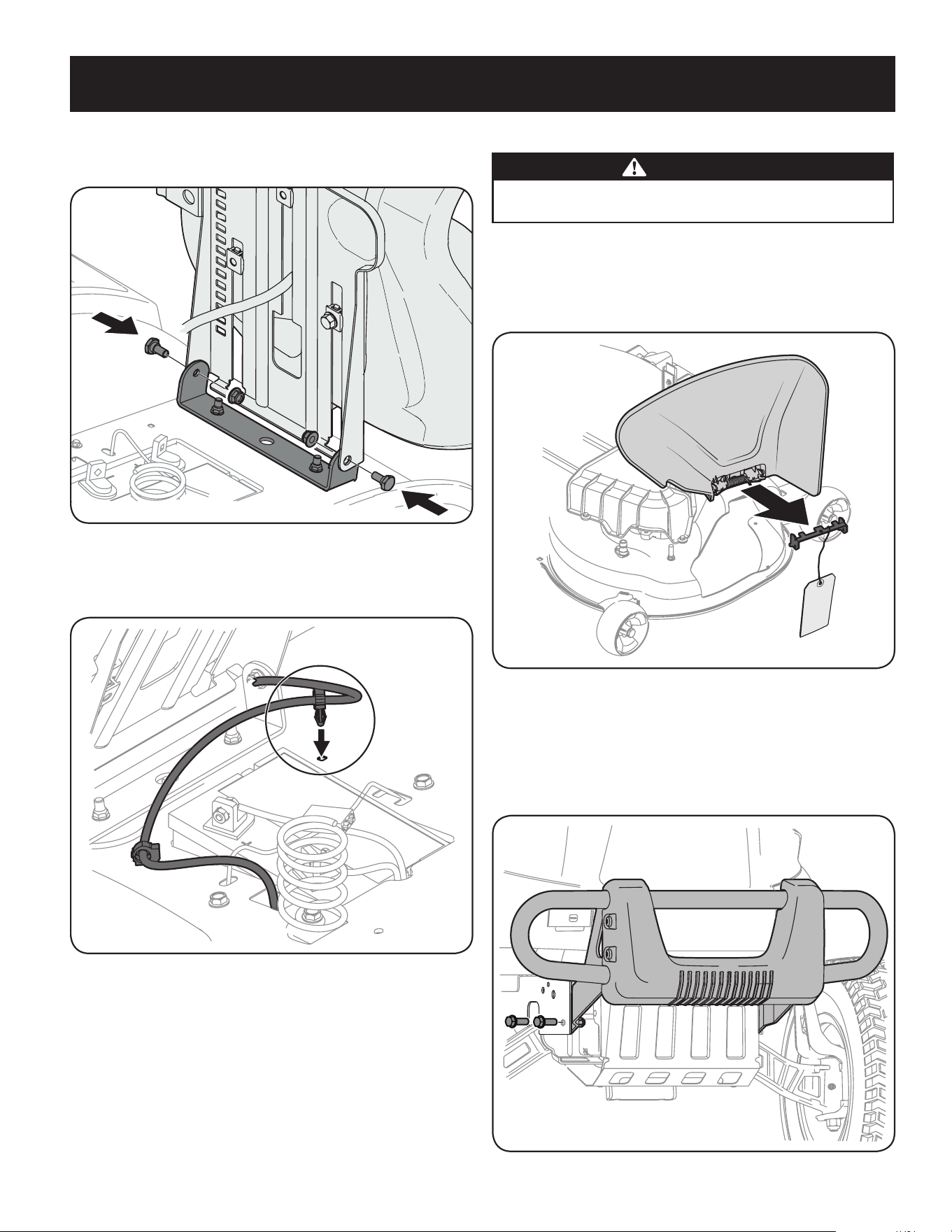
41
MONTAJE
3. Gire el asiento hasta la posición deseada y asegúrelo en su lugar con los tornillos de
reborde y las tuercas de seguridad con brida que extrajo antes. Tenga cuidado de
no doblar o dañar el cableado mientras instala el asiento. Vea la Figura 3.
Figura 3
4. Usando la traba del arnés unida al arnés, asegure el exceso de cable al
guardabarros colocando la traba del arnés en su lugar como se muestra
en la Figura 4.
Figura 4
Baje el deflector del canal de descarga de la plataforma
ADVERTENCIA
Nunca opere la plataforma de corte sin el deflector del canal de descarga
instalado y en posición baja.
Revise el equipo de corte para una traba de seguridad que puedan estar llevando
a cabo el deflector del canal alcista para el envío. Si la llave está presente, debe ser
removido antes de operar el tractor. Sosteniendo el deflector del canal hacia arriba
por completo, quite la traba de seguridad. Baje el deflector del canal y deseche la
traba de seguridad. Vea la Figura 5.
Figura 5
Instalación del paragolpes delantero
Los accesorios para fijar el paragolpes delantero se despachan instalados en el paragolpes.
1. Saque los cuatro tornillos hexagonales del paragolpes.
2. Coloque los soportes del paragolpes hacia el interior del bastidor del tractor y
fíjelos en su lugar con los cuatro tornillos hexagonales con reborde. Vea la Figura 6.
Figura 6
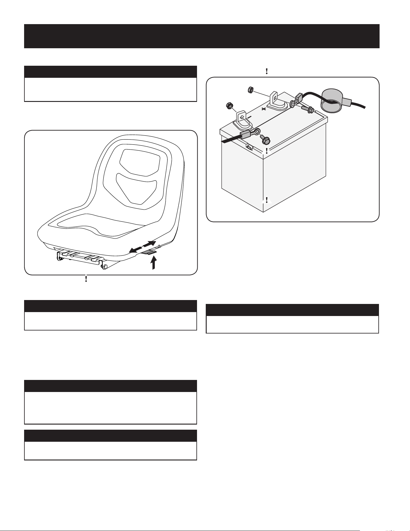
42
MONTAJE
Ajuste del asiento
ADVERTENCIA
Antes de hacer funcionar el tractor, compruebe que el asiento está enganchado
en el tope del asiento. Ponga el freno de mano. Párese detrás de la máquina y
tire el asiento hacia atrás hasta que haga clic al calzar en su lugar.
Para ajustar la posición del asiento, levante la palanca de ajuste del asiento. Deslice el asiento
hacia adelante o hacia atrás hasta la posición deseada; luego suelte la palanca de ajuste.
Asegúrese de que el asiento esté fijo en su posición antes de operar el tractor. Vea la Figura 7.
Figura 7
Control de la presión de los neumáticos
ADVERTENCIA
Se debe mantener una presión uniforme para todos los neumáticos en todo
momento. Consulte cuál es la presión adecuada en los laterales de los neumáticos.
Es posible que los neumáticos del tractor se hayan inflado demasiado para despacharlo.
Reduzca la presión de los neumáticos antes de hacer funcionar el tractor. Consulte en los
laterales de los neumáticos la presión máxima en psi.
NOTA: Es fundamental mantener una presión uniforme de los neumáticos para un
funcionamiento nivelado de la plataforma de corte.
Conexión de los cables de la batería
ADVERTENCIA
Advertencia Proposición 65 de California: Los bornes, los terminales y los accesorios
relacionados de la batería contienen plomo y compuestos de plomo, sustancias químicas
que según lo establecido por el Estado de California causan cáncer y daños en el sistema
reproductivo. Lávese las manos después de estar en contacto con estos componentes.
PRECAUCIÓN
Cuando coloque los cables de la batería, conecte siempre primero el cable
POSITIVO (rojo) a su borne, y a continuación el cable NEGATIVO (negro).
Por razones relacionadas con el envío, los dos cables de la batería de su equipo se pueden
haber dejado desconectados de los terminales en fábrica. Para conectar los cables de la
batería, proceda de la siguiente manera:
NOTA: El borne positivo de la batería está marcado como Pos (+). El borne
negativo de la batería está marcado como Neg (-).
NOTA: Si el cable positivo de la batería ya está conectado, siga con el paso 2.
1. Retire la cubierta plástica, si es que está presente, del borne positivo de la batería
y una el cable rojo al borne positivo de la batería (+) utilizando el perno y la tuerca
hexagonal. Vea la Figura 8.
Figura 8
2. Retire la cubierta plástica, si es que está presente, del borne negativo de la batería
y una el cable negro al borne negativo de la batería (–) utilizando el perno y la
tuerca hexagonal. Vea la Figura 8.
3. Coloque el capuchón de goma rojo por encima del borne positivo de la batería para
protegerlo contra la corrosión.
NOTA: Si la batería se pone en funcionamiento después de la fecha indicada en su
parte superior o al costado de la misma, cárguela siguiendo las instrucciones de la
sección Servicio de su Manual del Operador antes de hacer funcionar el tractor.
Ajuste de las ruedas de la plataforma
ADVERTENCIA
Mantenga las manos y los pies alejados de la abertura de descarga de la
plataforma de corte.
NOTA: Las ruedas de la plataforma constituyen un mecanismo para el cuidado del césped
y no fueron diseñadas para soportar el peso de la plataforma de corte.
Mueva el tractor a una superficie firme y nivelada, preferentemente sobre el pavimento, y
realice lo siguiente:
1. Controle la presión de los neumáticos, asegúrese que es la correcta e igual en todos
los neumáticos.
2. Asegúrese de que la plataforma está nivelada, de atrás hacia adelante y de
lado a lado. Consulte en la sección Mantenimiento y ajustes la información e
instrucciones para nivelar la plataforma.
3. Seleccione la posición de altura de la plataforma de corte colocando la palanca
de elevación de la plataforma en la configuración de altura de corte normalmente
deseada.
4. Controle si las ruedas están en contacto con la superficie de abajo o si hay excesiva
separación. Las ruedas de la plataforma deben tener entre ¼ y ½ pulgada de
separación respecto del suelo. Proceda como se indica a continuación para ajustar
las ruedas:
a. Levante el tirador de elevación de la plataforma hasta el punto más alto.
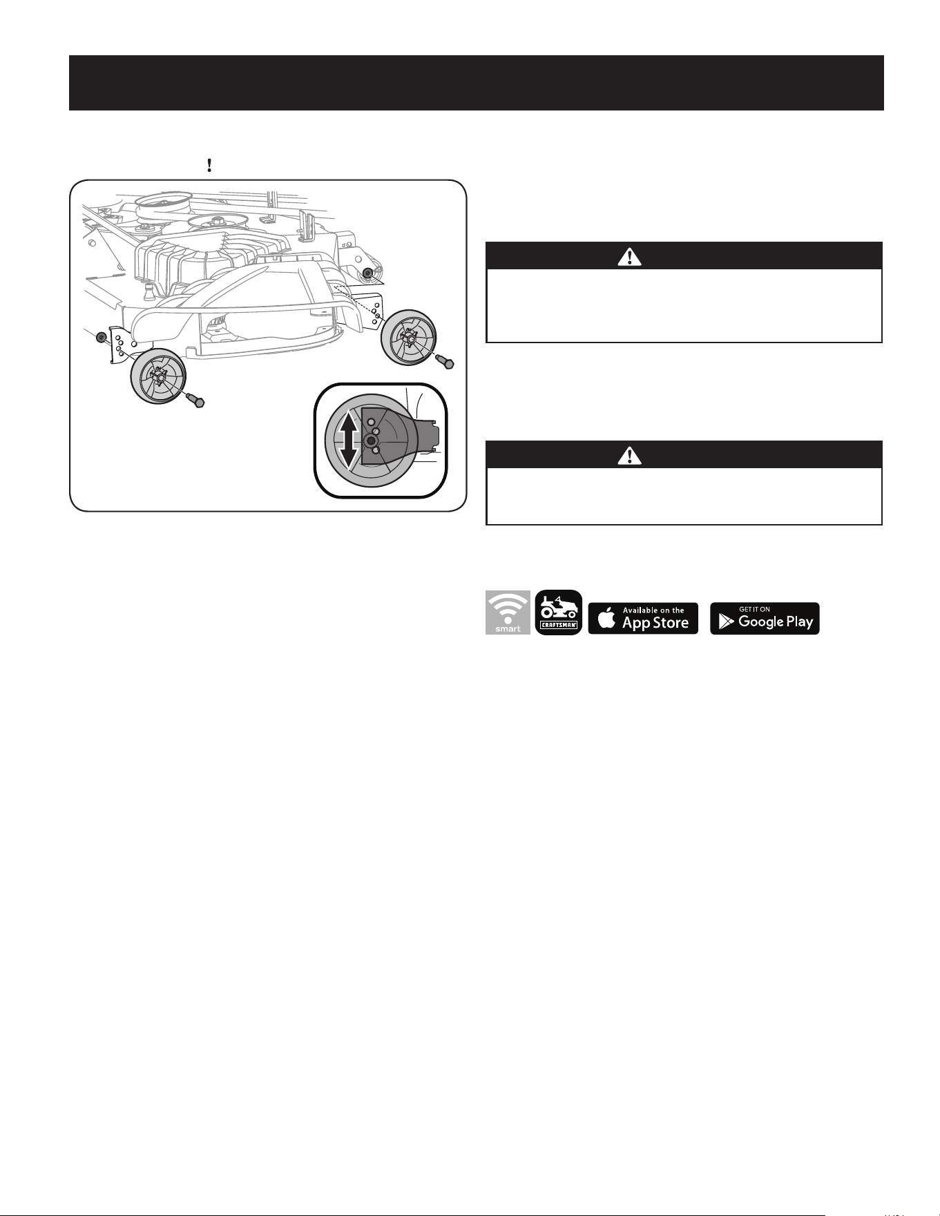
43
MONTAJE
b. Retire las ruedas delanteras y traseras de la plataforma retirando las
tuercas de seguridad con brida y los tornillos con reborde que las sujetan a
la plataforma. Vea la Figura 9.
Figura 9
c. Coloque la palanca de elevación de la plataforma en el ajuste de altura de
corte deseado.
d. Vuelva a insertar los pernos con reborde (con cada rueda de la plataforma)
dentro del orificio de posicionamiento que deja aproximadamente ½
pulgada entre la parte inferior de la rueda y el pavimento. Apriete la
tuerca de seguridad con brida y el tornillo con reborde hasta lograr entre
25 a 30 libras-pie con una llave de torsión.
NOTA: Consulte la sección Ajuste de la plataforma en la sección Mantenimiento y
Ajustes de este manual para obtener instrucciones detalladas sobre diferentes
ajustes de la plataforma.
Gasolina y aceite
El depósito de combustible se encuentra en la parte exterior/izquierda del tablero y
contiene 3 galones de gas. Extraiga la tapa de combustible girándola hacia la izquierda.
Sólo se debe utilizar gasolina limpia, nueva (con menos de 30 días de antigüedad) y sin
plomo. Llene el depósito sin superar el nivel del cuello de llenado para dejar espacio para
la dilatación del combustible.
ADVERTENCIA
Tenga mucho cuidado al trabajar con gasolina. La gasolina es sumamente inflamable y
sus vapores pueden causar explosiones. Nunca agregue combustible a la máquina en
espacios cerrados ni mientras el motor está caliente o funcionando. Apague cigarrillos,
cigarros, pipas y otras fuentes de combustión.
NOTA: Su tractor se despacha con aceite en el motor. Sin embargo, usted DEBE
controlar el nivel de aceite antes de hacerlo funcionar. Consulte el Manual del
operador del motor para obtener las instrucciones para controlar y agregar aceite.
Consulte la sección Servicio y mantenimiento del presente manual para conocer los
procedimientos para cambiar el aceite.
PRECAUCIÓN
Controle siempre el nivel de aceite del motor antes de cada uso según se indica en
el manual de funcionamiento del motor. Agregue aceite según sea necesario. De no
hacerlo se pueden producir daños graves al motor.
Activación de Bluetooth® inteligente Césped App (Si
está equipado)
Tome el control de su cuidado del césped con la aplicación Smart Lawn habilitada para
Bluetooth® de Craftsman. Consejos de mantenimiento, seguimiento del clima y más:
todo lo que necesita para mantener el mejor patio de la cuadra ahora está en un solo
lugar. Smart Lawn también proporciona instrucciones paso a paso y videos tutoriales
para mostrarle cómo mantener su cortacésped funcionando correctamente. Además,
puede solicitar las piezas que necesita directamente desde la aplicación. La aplicación
también rastrea la carga de la batería de la cortadora de césped, así como el estado de
otros componentes clave de reemplazo como aceite, cuchilla y filtro de aire.
¡Conecte su cortadora de césped habilitada para Bluetooth® descargando la aplicación
GRATUITA Craftsman Smart Lawn para comenzar a usar todas las nuevas características
de conectividad de su jinete Craftsman! Descárguelo GRATIS de App Store o Google Play
(funciona con dispositivos con iOS 9, Android 4.4 y versiones posteriores).
Primero, configure la configuración Bluetooth® de su teléfono inteligente en la posición
'ENCENDIDO'. A continuación, deberá crear su cuenta. La aplicación le pedirá que ingrese
el número de modelo y el número de serie de su cortacésped. A continuación, intentará
conectarse con la cortadora de césped a través de Bluetooth®.
Para sincronizar su teléfono con la cortadora de césped, encienda su cortadora de
césped de modo que el motor esté en funcionamiento, mantenga su dispositivo a una
distancia de 150 pies de la podadora y asegúrese de que la batería de la podadora
esté completamente cargada. Recuerde poner la llave en la posición 'OFF' después de
conectar para no drenar la carga de la batería (si no está funcionando la cortadora de
césped).
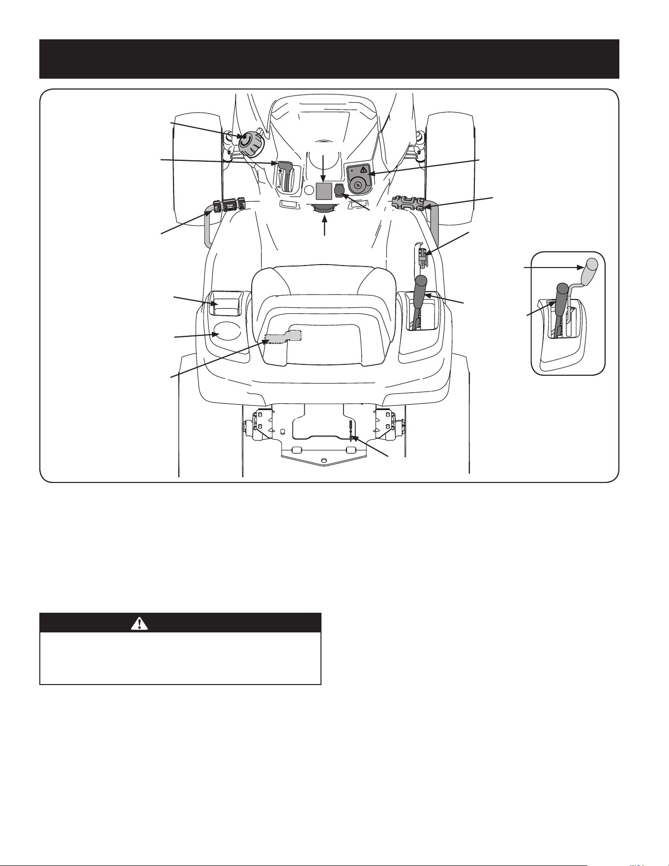
44
FUNCIONAMIENTO
Tapón del depósito de combustible
Palanca de control del
acelerador/cebador
Pedal de freno
Bandeja de almacenamiento
Portavasos
Palanca de ajuste del asiento
Varilla de derivación
de la transmisión
Palanca de elevación
de la plataforma
Pedal de marcha atrás
Pedal de marcha adelante
Palanca del freno de
de mano/control de crucero
Módulo de encendido
PTO Switch
Medidor horario
Manija de la PTO
Manija de la PTO
Modelo
Figura 10
Ahora que ya ha ajustado su tractor cortacésped para el funcionamiento, es importante
familiarizarse con sus controles y características. Consulte la Figura 10.
NOTA: Este manual de operación cubre distintos modelos. Las características del tractor
pueden variar según los modelos. No todas las características que se incluyen en este
manual se aplican a todos los modelos de tractor y la máquina que se ilustra aquí puede
diferir de la suya.
NOTA: Las referencias a IZQUIERDA, DERECHA, ADELANTE Y ATRÁS indican esa posición
desde el asiento del operador en el tractor, mirando hacia adelante.
ADVERTENCIA
Lea y observe todas las normas e instrucciones de seguridad de este manual,
incluida toda la sección de funcionamiento, antes de poner esta máquina en
funcionamiento. Si no se respetan todas las normas e instrucciones de seguridad
se pueden provocar lesiones.
Pedal de marcha adelante
El pedal de marcha adelante está ubicado a la derecha de la máquina, sobre el estribo.
Presione el pedal de marcha adelante hacia adelante para que el tractor se mueva en esa
dirección. La velocidad absoluta también se controla con el pedal de marcha adelante.
Cuanto más se presione el pedal hacia adelante, más rápido se moverá el tractor. El pedal
volverá a su posición original cuando deje de oprimirlo.
Pedal de marcha atrás
El pedal de marcha atrás está ubicado a la derecha del tractor, sobre el estribo. La
velocidad absoluta también se controla con el pedal de marcha atrás. Cuanto más presione
el pedal hacia abajo, más rápido se moverá el tractor. El pedal volverá a su posición
original cuando deje de oprimirlo.
Pedal de freno
El pedal del freno está ubicado del lado izquierdo del tractor, sobre el estribo. El pedal del
freno se puede usar para detener el tractor o para colocar el freno de mano.
NOTA: Se debe oprimir a fondo el pedal del freno para activar el interruptor de
interbloqueo de seguridad al arrancar el tractor.
Pedal de bloqueo del diferencial (si está incluido)
El pedal de bloqueo del diferencial está ubicado a la izquierda del tractor, hacia
la parte trasera del estribo cerca de la caja del asiento. La activación del bloqueo
del diferencial aumenta la tracción al mantener la misma velocidad de ruedas en
las ruedas traseras. Consulte la sección Bloqueo del diferencial para obtener más
información sobre el uso del bloqueo del diferencial.
Palanca de ajuste del asiento
La palanca de ajuste del asiento está ubicada debajo del asiento, a la izquierda. La palanca
permite ajustar el asiento del operador hacia adelante o hacia atrás. Consulte la sección
Montaje y Configuración para ver instrucciones sobre el ajuste de la posición del asiento.
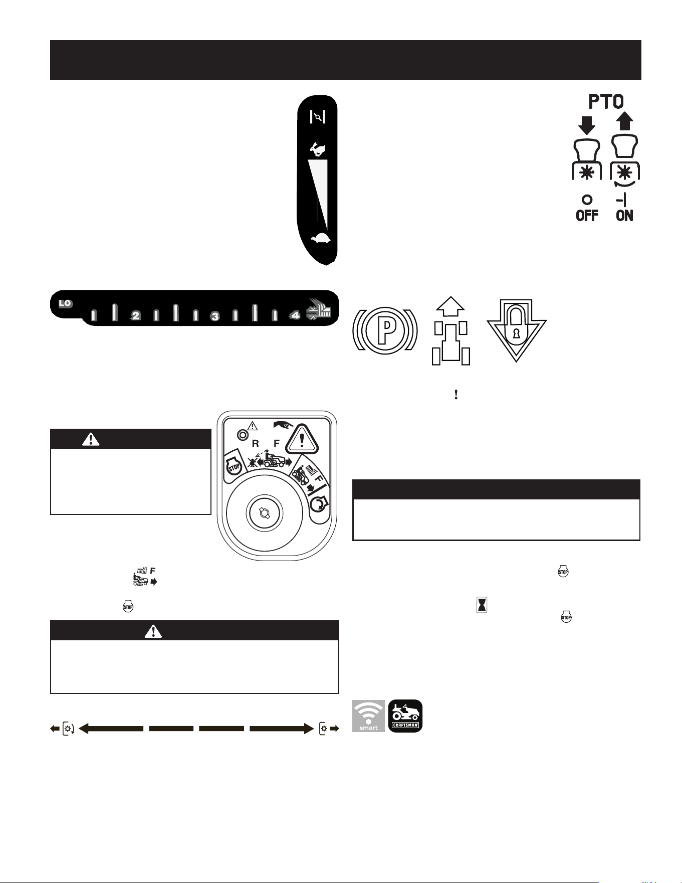
45
FUNCIONAMIENTO
Palanca de control del acelerador/cebador
La palanca de control del acelerador/cebador está ubicada del lado izquierdo
del tablero de instrumentos del tractor. Esta palanca controla la velocidad
del motor y, cuando se la empuja completamente hacia adelante, más
allá de la posición de detención, también cierra el cebador para arranques
en frío. Cuando se lo coloca en una posición determinada, el acelerador
mantiene una velocidad de motor uniforme.
NOTA: Cuando opere el tractor con la plataforma de corte colocada,
asegúrese de que la palanca del acelerador/cebador esté siempre en
la posición FAST (rápido).
Palanca de elevación de la plataforma
La palanca de elevación se encuentra en el guardabarros derecho y se utiliza para levantar
y bajar la plataforma. Tire de la palanca hacia la izquierda para sacarla de la muesca
y empuje hacia abajo para bajar la plataforma o hacia arriba para levantarla. Cuando
alcance la altura deseada, mueva la palanca de elevación hacia la derecha para que encaje
totalmente en la muesca de posición.
Módulo de encendido
ADVERTENCIA
Nunca deje la máquina en funcionamiento
sin vigilancia. Siempre desconecte la toma de
fuerza (PTO), ponga el freno de mano, pare
el motor y retire la llave, para evitar que el
motor arranque accidentalmente.
Para arrancar el motor, inserte la llave en el
interruptor de encendido y gírela en el sentido de
las agujas del reloj hacia la posición
START (arranque). Suelte la llave en la posición
MODO NORMAL DE CORTE una vez que haya arrancado el motor.
Para detener el motor, gire la llave de encendido en sentido contrario a las agujas del reloj
hasta la posición STOP (parar).
PRECAUCIÓN
Antes de operar el tractor, consulte Interruptores de interbloqueo de seguridad
y Arranque del motor en la sección Funcionamiento de este manual para
ver instrucciones detalladas del Módulo del interruptor de encendido y del
funcionamiento del tractor en el MODO PRECAUCIÓN MARCHA ATRÁS
Manija de toma de fuerza (PTO)/activación de las cuchillas
La manija de la PTO/de activación de las cuchillas está ubicada en el guardabarros derecho.
Al activar la PTO se conecta la energía a la plataforma de corte y a otros accesorios
(disponibles por separado). Consulte la sección Funcionamiento para ver información e
instrucciones sobre cómo usar la PTO.
Nota: PTO significa toma de fuerza, que es un mecanismo para tomar energía
de una fuente de alimentación, como un motor en marcha y transmitirla a una
aplicación como la cuchilla de corte de esta cortadora de césped.
Interruptor de la toma de fuerza (PTO)
El interruptor de la PTO está ubicado en el tablero de instrumentos a
la derecha del LCD avisador de servicio y medidor horario.
Al activar la PTO se conecta la energía a la plataforma de corte y a
otros accesorios (disponibles por separado).
Varilla de derivación de la transmisión
La varilla de derivación de la transmisión se encuentra en la parte
trasera del tractor en la sección inferior derecha del bastidor.
Cuando se engancha, la varilla abre una derivación dentro de las
transmisiones hidrostáticas, lo cual permite empujar el tractor a mano distancias cortas.
Consulte la sección Montaje y Configuración para obtener instrucciones sobre el uso de la
función de derivación.
Palanca del freno de mano/control de crucero
La palanca de freno de mano/control de crucero, que está ubicada en el centro del tablero de
instrumentos del tractor, debajo del volante, se utiliza para aplicar el freno de mano y el control
de crucero. Consulte la sección Funcionamiento de este manual para ver instrucciones detalladas
sobre el freno de mano.
NOTA: Si el operador abandona el asiento y deja el motor en funcionamiento,
deberá colocar el freno de mano, o el motor se apagará de forma automática.
NOTA: El control de crucero NO podrá activarse a la velocidad absoluta más rápida
del tractor.
ADVERTENCIA
Nunca deje la máquina en funcionamiento sin vigilancia. Siempre desconecte
la PTO, ponga el freno de mano, pare el motor y retire la llave, para evitar que
arranque accidentalmente.
LCD avisador de servicio y medidor horario (Si está
equipado)
Cuando se gira la llave de encendido para sacarla de la posición STOP (parada), pero no
para llevarla hasta la posición START (arranque), el LCD avisador de servicio y medidor horario
mostrará brevemente el voltaje de la batería, seguido de las horas acumuladas del tractor.
NOTA: Las horas de funcionamiento del tractor se registran cada vez que
se gira la llave de encendido para sacarla de la posición STOP (parada),
independientemente de si el motor arranca.
El LCD avisador de servicio le recuerda al operador os intervalos de mantenimiento para el
cambio del aceite del motor, el servicio del filtro de aire, las advertencias de bajo nivel de
aceite y poca batería.
App Smart Lawn (Si está equipado)
El tablero de mantenimiento automatizado y el registro de la aplicación le ayudarán a
mantener su máquina funcionando al máximo rendimiento y protegerán su inversión
con el seguimiento total de horas durante toda la vida útil de su equipo.
Reciba notificaciones cuando ha llegado el momento de realizar las tareas esenciales
de mantenimiento. Su tablero le proporciona monitorización en tiempo real y le indica
cuándo debe verificar o cambiar el aceite, el filtro de aire, las cuchillas o la batería. La
aplicación también le permite localizar y contactar con centros de servicio, acceder a
instrucciones detalladas para realizar mantenimiento de rutina y adquirir repuestos
directamente desde su dispositivo móvil.
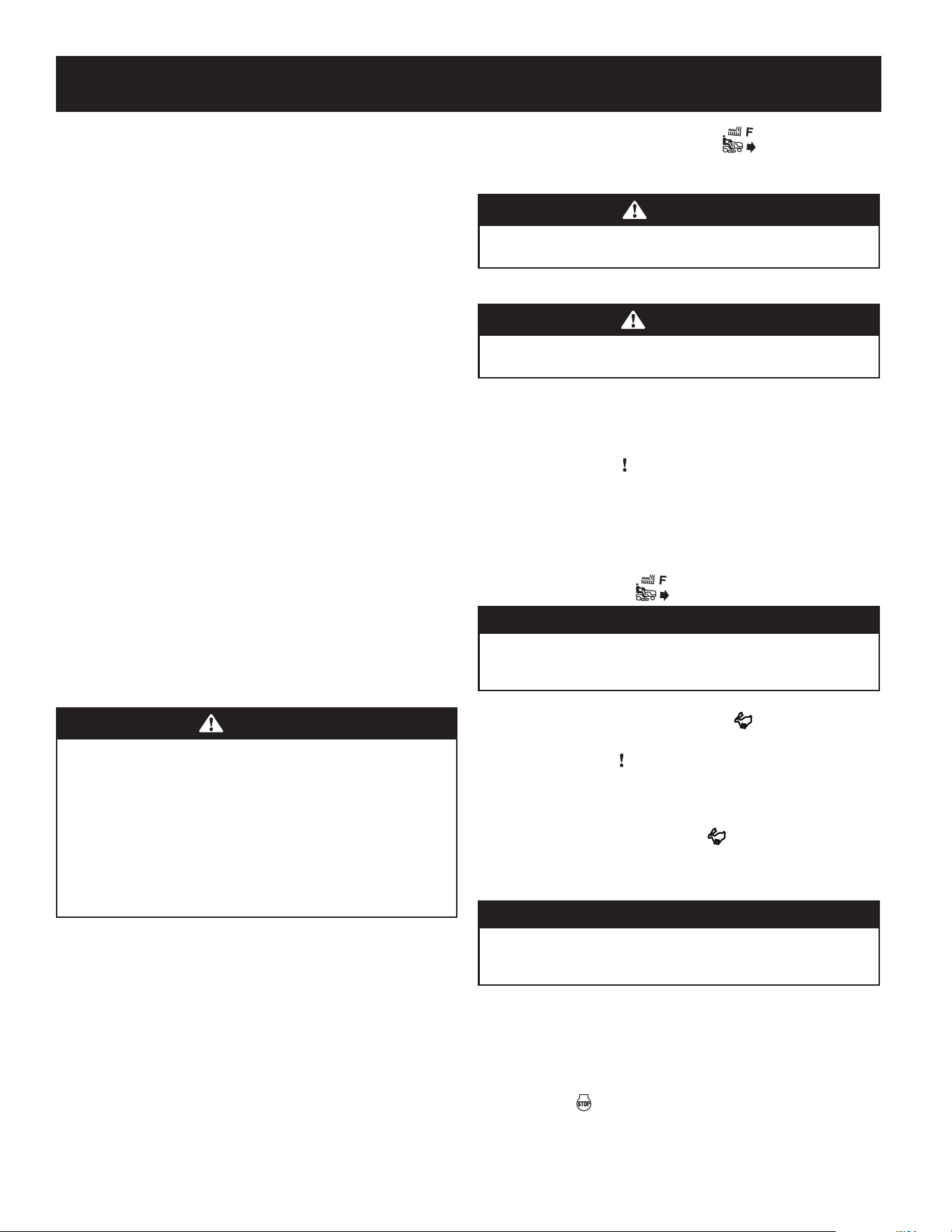
46
FUNCIONAMIENTO
Cambiar el aceite
El LCD mostrará las letras "CHG" (cambiar), seguidas de las letras "OIL" (aceite), seguidas de las
letras "SOON" (pronto), y luego finalmente seguidas por el tiempo acumulado del medidor.
“CHG/OIL/SOON/TIME” se alternarán en la pantalla durante 7 minutos después de que el
medidor llegue a 50 horas. Este intervalo del avisador de servicio de aceite se producirá cada
50 horas. Antes de que caduque el intervalo, agregue el aceite como se indica en la sección
Mantenimiento del Manual del operador del motor.
Función "Nivel bajo de aceite" (si está instalada)
Las letras “LO” (poco) seguidas de las letras “OIL” (aceite), seguidas luego del tiempo
acumulado del medidor indicarán que el tractor tiene poco aceite. Cuando un motor no está en
funcionamiento e inmediatamente después de que el motor arranca, la presión de aceite puede
estar baja. Esto puede activar el texto "LO" "OIL" (nivel bajo de aceite). Esto es normal. Si la
indicación de nivel bajo de aceite persiste, pare el tractor inmediatamente y compruebe el nivel
de aceite del motor según las instrucciones del Manual del operador del motor.
NOTA: La función “LOW OIL” (nivel bajo de aceite) solo funciona si el motor tiene
un interruptor de presión de aceite.
Poca batería
Al arrancar, se visualiza fugazmente el voltaje de la batería y luego cambia a horas
acumuladas. Aparecen las letras “LO” (poco), seguidas de las letras “BATT” (batería),
seguidas luego del tiempo acumulado del medidor. "LO/BATT/TIME" se muestra en la
pantalla LCD cuando la tensión cae por debajo de 11.5 voltios. Cuando esto ocurre, significa
que se debe cargar la batería o que el sistema de carga del motor no genera suficiente
amperaje. Cargue la batería como se indica en la sección Servicio de este manual o haga
controlar el sistema de carga por su distribuidor de servicio local.
Mantenimiento del filtro de aire
Aparecen las letras “CLN” (limpiar), seguidas de las letras “AIR” (aire), seguidas por "FILT",
seguidas luego del tiempo acumulado del medidor. “CLN/AIR/FILT/TIME” se alternarán en
la pantalla durante 7 minutos después de que el medidor llegue a 50 horas. Este intervalo
del avisador de servicio del filtro de aire será cada 50 horas. En intervalos comunes con el
servicio del aceite, aparece el mensaje del aceite primero seguido por el mensaje del filtro
de aire.
Funcionamiento
ADVERTENCIA
Evite lesiones graves o la muerte. Recorra las pendientes hacia arriba y hacia
abajo, no de manera transversal. Evite realizar giros abruptos. No utilice el tractor
en lugares donde podría resbalar o volcar. Si la máquina se para mientras sube la
pendiente, pare la PTO y retroceda lentamente por la pendiente. Mantenga todos
los dispositivos de seguridad (guardas, protectores e interruptores) en su lugar
y funcionando. Extraiga los objetos que podrían ser arrojados por las cuchillas.
Conozca la ubicación y función de todos los controles. Asegúrese de que las
cuchillas y el motor se han detenido antes de colocar las manos o los pies cerca de
las cuchillas. Antes de abandonar la posición del operador, active la toma de fuerza
(PTO) y ponga el freno de mano, apague el motor y retire la llave.
Interruptores de interbloqueo de seguridad
Este tractor está equipado con un sistema de interbloqueo de seguridad para protección
del operador. Si el sistema de interbloqueo llegara a funcionar mal, no opere el tractor.
Comuníquese con un distribuidor de servicio autorizado.
• El sistema de interbloqueo de seguridad impide que el motor arranque o se
encienda a menos que esté colocado el freno de mano, y la PTO esté DESACTIVADA
en la posición de apagado (OFF).
• Si el operador abandona su asiento antes de colocar el freno de mano, el motor se
apagará automáticamente.
• Si el operador abandona el asiento del tractor con la PTO ACTIVADA en la posición
de encendido (ON), el embrague de la PTO se apaga de manera automática,
independientemente de que el freno de mano esté puesto o no.
• Con la llave de encendido en la CORTE NORMAL , el embrague de la PTO se
apagará automáticamente si se mueve la PTO a la posición ACTIVADA (ON) con el
pedal de marcha en posición de marcha atrás.
ADVERTENCIA
No opere el tractor si el sistema de interbloqueo funciona mal. El sistema fue diseñado
para brindarle seguridad y protección.
Encendido del motor
ADVERTENCIA
No opere el tractor si el sistema de interbloqueo funciona mal. El sistema fue
diseñado para brindarle seguridad y protección.
NOTA: Consulte la sección Montaje y Configuración de este manual para ver instrucciones
sobre el llenado de aceite y gasolina.
1. Inserte la llave del tractor en el módulo del interruptor de encendido.
2. Coloque la PTO en la posición desactivada (OFF).
3. Aplique completamente el freno del tractor.
4. Mueva el control del acelerador/cebador a la posición CHOKE (cebador).
NOTA: Si el motor está caliente, tal vez no sea necesario cebar el motor.
5. Gire la llave de encendido en el sentido de las agujas del reloj hasta la posición
START (arranque). Una vez que arranque el motor, suelte la llave. Volverá a la
posición NORMAL MOWING (corte normal).
PRECAUCIÓN
NO mantenga la llave en la posición START (arranque) durante más de diez
segundos por vez. Si lo hace, puede ocasionar daños al arrancador eléctrico del
motor.
6. Una vez que el motor arranca, tire del control del acelerador/cebador (si está
equipado) hacia abajo a la posición FAST (rápido), o empuje el control del
cebador (si está equipado) hacia abajo a la posición OFF (apagado).
NOTA: NO deje el control del cebador activado mientras opera el tractor. Si lo
hace, se generará una mezcla de combustible “rica”, lo cual hará que el motor no
funcione bien y pueda ser dañado.
NOTA: Cuando haga funcionar el tractor asegúrese de que la palanca del
acelerador esté siempre en la posición FAST (rápida). Funcionar con el
acelerador a menos de máxima velocidad puede acortar la vida útil de la batería.
Detención del motor
ADVERTENCIA
Si golpea contra un objeto extraño, detenga el motor y desconecte los cables
de la bujía. Inspeccione minuciosamente la máquina para ver si está dañada.
Repare el daño antes de volver a encender el motor y operar la máquina.
1. Si las cuchillas están ACTIVADAS (ON) coloque la PTO en la posición
DESACTIVADA (OFF).
2. Ponga el acelerador cerca de la posición SLOW (lento).
3. Ponga el freno de mano.
4. Gire la llave de encendido en el sentido contrario a las agujas del reloj hasta la
posición STOP (parar).
5. Retire la llave del interruptor de encendido para evitar que alguien encienda
accidentalmente el motor.
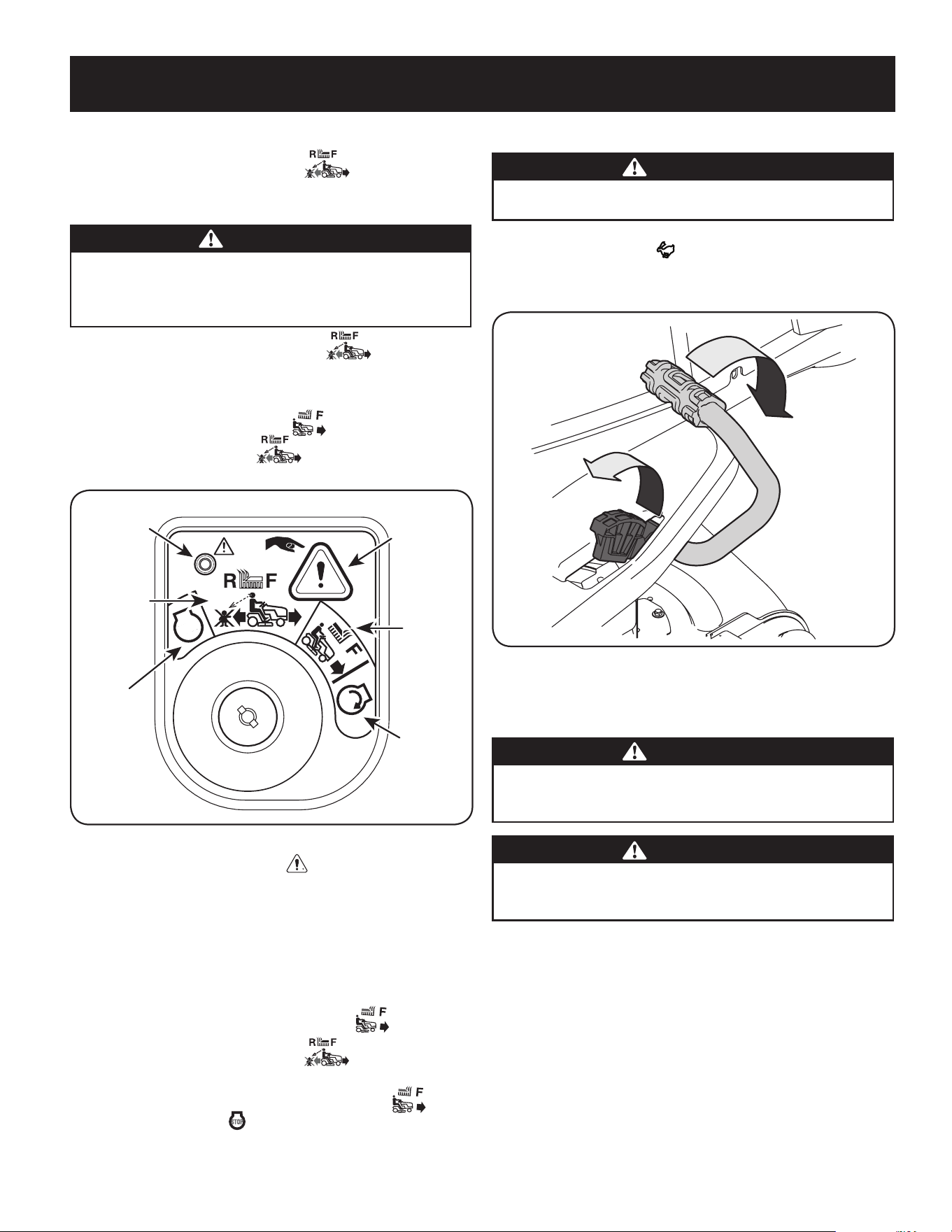
47
FUNCIONAMIENTO
Modo marcha atrás con precaución
La posición MODO MARCHA ATRÁS CON PRECAUCIÓN del módulo de encendido
permite operar el tractor marcha atrás con la (PTO) de las cuchillas activada.
NOTA: No se recomienda cortar el césped en marcha atrás.
ADVERTENCIA
Tenga mucho cuidado cuando opere el tractor en MODO DE PRECAUCIÓN EN
MARCHA ATRÁS. Mire siempre hacia abajo y detrás de usted antes y durante la
marcha atrás. No haga funcionar el tractor cuando haya niños u otras personas
cerca. Detenga el tractor inmediatamente si alguien se acerca.
Para utilizar el MODO DE PRECAUCIÓN EN MARCHA ATRÁS :
NOTA: El operador DEBE estar sentado en el asiento del tractor.
1. Arranque el motor como se indicó en la página anterior.
2. Gire la llave de la posición CORTE NORMAL (verde) a la posición MODO
MARCHA ATRÁS CON PRECAUCIÓN (amarillo) del módulo de encendido.
Vea la Figura 11.
Figura 11
3. Oprima el PULSADOR DE MARCHA ATRÁS en el ángulo superior derecho
del módulo de encendido. La luz indicadora roja que está en el ángulo superior
izquierdo del módulo de encendido se mantendrá ENCENDIDA mientras está
activada. Vea la Figura 11.
4. Una vez activada (luz indicadora ENCENDIDA), el tractor podrá operar en marcha
atrás con las cuchillas de corte (PTO) activadas.
5. Siempre mire hacia abajo y hacia atrás antes y mientras se desplaza marcha
atrás, para verificar que no haya niños cerca. Luego de volver a desplazarse hacia
adelante, vuelva la llave a la posición de CORTE NORMAL .
6. El MODO DE PRECAUCIÓN EN MARCHA ATRÁS permanecerá activado
hasta que:
a. La llave se coloque ya sea en la posición CORTE NORMAL o la
posición de parada o bien
b. El operador abandone el asiento (PTO eléctrica)/se ponga el freno de
mano (PTO manual).
Conducción del tractor
ADVERTENCIA
Evite arrancar súbitamente, desarrollar excesiva velocidad y detenerse de
repente.
1. Presione levemente el pedal del freno para liberar el freno de mano. Mueva el
acelerador a la posición FAST (rápido).
2. Para conducir hacia ADELANTE, presione lentamente el pedal de marcha adelante
hasta alcanzar la velocidad deseada. Vea la Figura 12.
Marcha directa
Marcha atrás
Figura 12
3. Para conducir MARCHA ATRÁS, verifique que el área de atrás esté despejada; Luego
presione lentamente hacia adelante el pedal de marcha atrás hasta alcanzar la
velocidad deseada. Vea la Figura 12.
PRECAUCIÓN
NO intente cambiar la dirección de desplazamiento mientras el tractor está en
movimiento. Siempre debe detener el tractor completamente antes de cambiar
de marcha adelante a marcha atrás o viceversa.
ADVERTENCIA
No abandone el asiento del tractor sin antes colocar la PTO en posición
DESACTIVADA (OFF) y poner el freno de mano. Si deja el tractor sin vigilancia,
apague el motor y retire la llave de encendido.
Luz
indicadora
Posición de
modo de
precaución en
marcha atrás
Posición de
detención
Botón de
marcha atrás
Modo de
marcha
normal
Posición
de arranque
DETENCIÓN
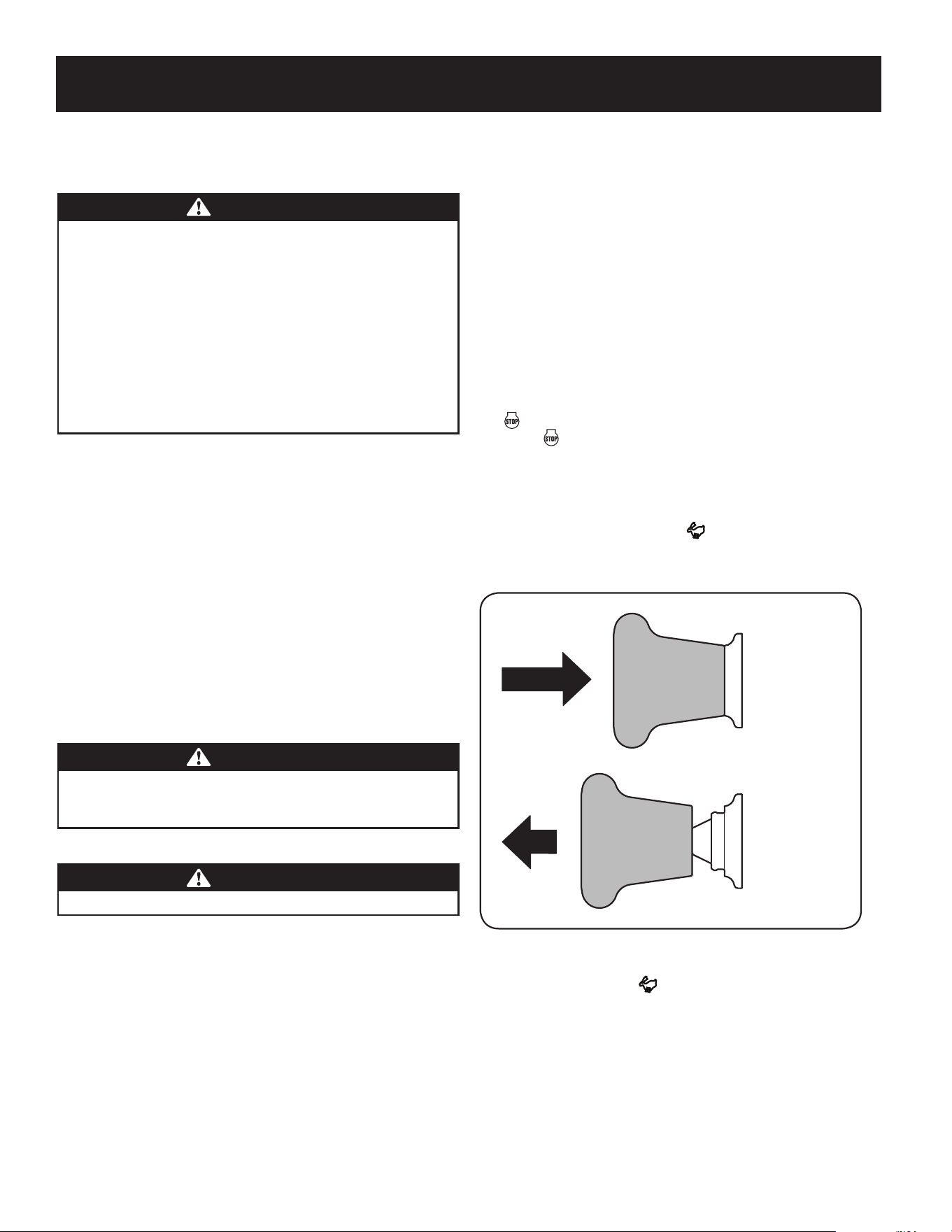
48
FUNCIONAMIENTO
Operación en pendientes
Consulte la sección INDICADOR DE PENDIENTE en la página 8 para determinar en qué
pendientes puede operar el tractor de manera segura.
ADVERTENCIA
No corte en pendientes con una inclinación de más de 15 grados (elevación
aproximada de 2½ pies por cada 10 pies). El tractor podría darse vuelta y causar
lesiones graves. En las pendientes corte hacia arriba y hacia abajo, NUNCA
en forma transversal. Tenga mucho cuidado al cambiar de dirección en una
pendiente. Esté atento a los hoyos, surcos, baches, rocas u otros objetos ocultos.
El terreno desnivelado puede voltear la máquina. El césped alto puede ocultar
obstáculos. Evite realizar giros cuando opere en una pendiente. Si debe realizar
un giro, hágalo pendiente abajo. Subir una pendiente aumenta enormemente
las posibilidades de que el vehículo dé una vuelta de campana. Evite detenerse
cuando suba una pendiente. Si fuese necesario detenerse mientras sube una
pendiente, arranque suave y cuidadosamente para reducir la posibilidad de que
el tractor se dé vuelta hacia atrás.
Colocación del freno de mano
NOTA: Si el operador abandona el asiento y deja el motor en funcionamiento, deberá
colocar el freno de mano, o el motor se apagará de forma automática.
Para poner el freno de mano:
1. Presione el pedal de freno completamente hacia abajo con el pie izquierdo y
manténgalo en esa posición.
2. Presione la palanca del freno de mano/control de crucero hacia abajo y
manténgala en esa posición.
3. Retire el pie del pedal del freno.
4. Afloje la presión sobre la palanca del freno de mano/control de crucero.
5. Después de completar el paso 3, el pedal de freno debe permanecer en la posición
hacia abajo. Si no lo hace, el freno de mano no está activado. Repita los pasos 1 a 4
para la activación.
Para desactivar el freno de mano, presione suavemente el pedal de freno.
ADVERTENCIA
Nunca deje la máquina en funcionamiento sin vigilancia. Siempre desconecte
la PTO, ponga el freno de mano, pare el motor y retire la llave, para evitar que
arranque accidentalmente.
Ajuste del control de crucero
ADVERTENCIA
Nunca active la palanca de control de crucero mientras se desplaza marcha atrás.
Para fijar el control de crucero:
1. Presione lentamente el pedal de marcha adelante con el pie derecho hasta
alcanzar la velocidad deseada.
2. Presione la palanca del freno de mano/control de crucero hacia abajo y
manténgala en esa posición..
3. Retire el pie del pedal de marcha adelante.
4. Afloje la presión sobre la palanca del freno de mano/control de crucero.
5. Después de completar el paso 3, el pedal de marcha adelante debe permanecer en
la posición hacia abajo y el tractor mantendrá la misma velocidad de avance. Si no
lo hace, el control de crucero no está activado. Repita los pasos 1 a 4 para activar el
control de crucero.
Para desactivar el control de crucero, presione suavemente el pedal de marcha adelante o el
pedal de freno.
NOTA: El control de crucero no se puede fijar en la velocidad absoluta más
rápida del tractor. Si el operador intentara hacerlo, el tractor se desacelerará
automáticamente a la velocidad de corte absoluta óptima y más rápida.
Para cambiar la dirección de desplazamiento de marcha adelante a marcha atrás cuando
está activado el control de crucero, oprima el pedal de freno para desactivarlo y haga que el
tractor se detenga por completo. Luego presione lentamente el pedal de marcha atrás con la
almohadilla del pie para desplazarse marcha atrás.
Uso de la palanca de elevación de la plataforma
Para subir o bajar la plataforma de corte, mueva la palanca de elevación hacia la izquierda
y luego colóquela en la muesca que mejor se adapte a la aplicación deseada.
Funcionamiento de los faros delanteros
Los faros están ENCENDIDOS cuando se gira la llave de encendido fuera de la posición
STOP . Los faros se apagan (OFF) cuando se coloca la llave de encendido en la
posición STOP .
Activación de la PTO (Tractores con PTO eléctrica)
Al conectar la PTO se suministra energía a la plataforma de corte y a otros accesorios
(disponibles por separado). Para conectar la PTO:
1. Mueva el acelerador a la posición FAST (rápido).
2. Empuje la palanca de la PTO hacia adelante a la posición de activación (ON).
Vea la Figura 13.
ON
OFF
Figura 13
NOTA: Cuando haga funcionar el tractor asegúrese de que el acelerador esté
siempre en la posición FAST (rápida). Funcionar con el acelerador a menos
de máxima velocidad puede acortar la vida útil de la batería producir un corte de
mala calidad.
3. Para desactivar la PTO, tire de la palanca de la PTO hacia atrás a la posición de
desactivación (OFF).
(apagado)
(encendido)
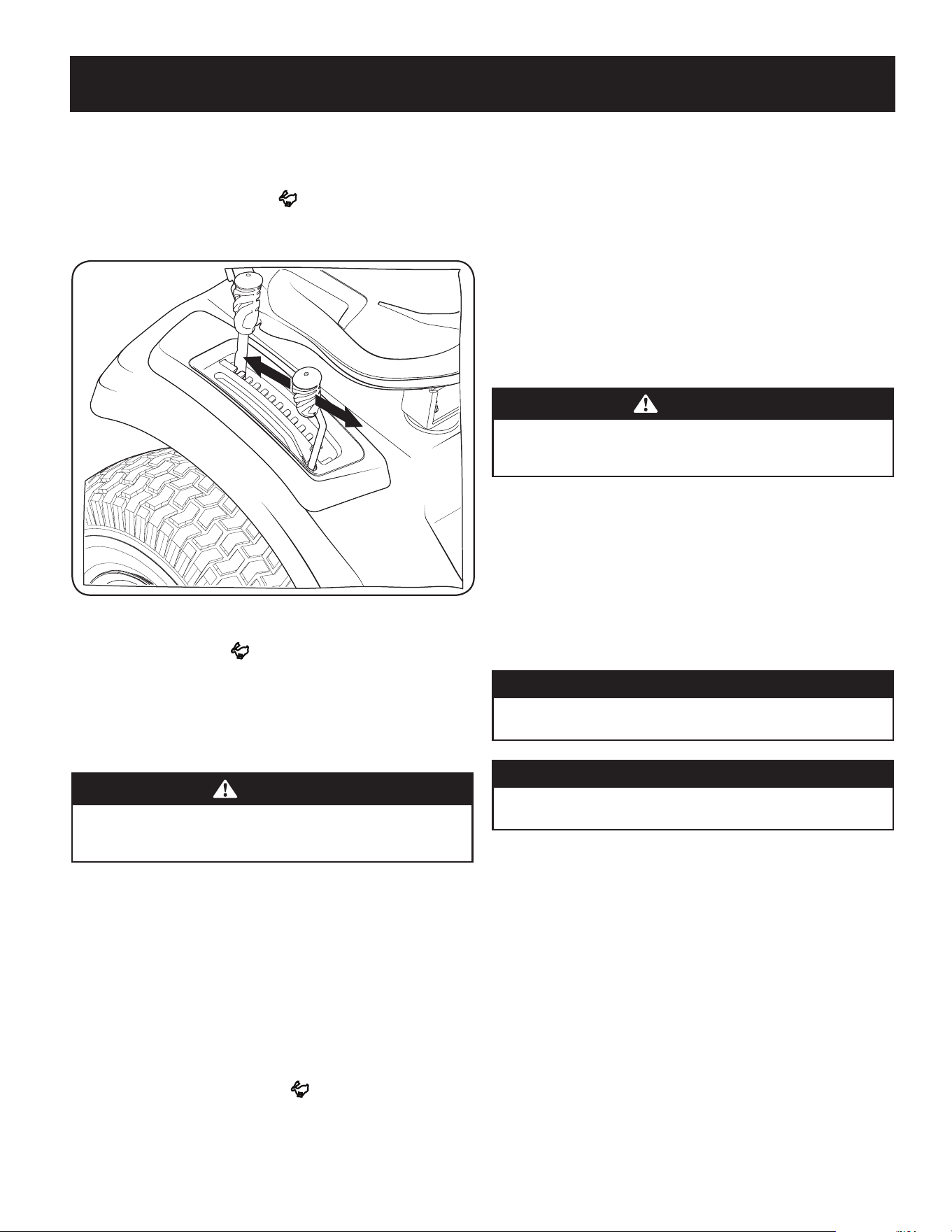
49
FUNCIONAMIENTO
Conexión de la toma de fuerza (Manual PTO de tractor)
Al conectar la PTO se suministra energía a la plataforma de corte y a otros accesorios
(disponibles por separado). Para conectar la PTO:
1. Mueva el acelerador a la posición FAST (rápido).
2. Empuje la palanca de la PTO hacia adelante a la posición de activación (ON).
Vea la Figura 13.
Figura 14
NOTA: Cuando haga funcionar el tractor asegúrese de que el acelerador esté
siempre en la posición FAST (rápida). Funcionar con el acelerador a menos
de máxima velocidad puede acortar la vida útil de la batería producir un corte de
mala calidad.
3. Para desactivar la PTO, tire de la palanca de la PTO hacia atrás a la posición de
desactivación (OFF).
Corte de césped
ADVERTENCIA
Asegúrese de que el área donde se va a cortar esté libre de desechos, ramitas,
piedras, cables u otros objetos que puedan ser arrojados por las cuchillas
rotativas.
NOTA: No enganche la plataforma de corte cuando esté baja sobre el pasto. Se produce
el desgaste prematuro y la posible falla de la correa y del embrague de la PTO. Antes de
enganchar la plataforma de corte, levante totalmente la plataforma o lleve la máquina a
un área donde no haya césped.
1. Corte en las pendientes hacia arriba y hacia abajo, no de manera transversal.
2. Evite realizar giros cuando opere en una pendiente. Si debe realizar un giro, hágalo
pendiente abajo. Subir una pendiente aumenta enormemente las posibilidades de
que el vehículo dé una vuelta de campana.
3. Evite detenerse cuando suba una pendiente. Si fuese necesario detenerse mientras
sube una pendiente, comience suave y con cuidado para reducir la posibilidad de
que el tractor se dé vuelta hacia atrás.
4. Coloque el acelerador en la posición FAST (rápido) y active la PTO.
5. Baje la plataforma de corte al ajuste de altura deseado usando la manija de
elevación de la plataforma.
6. Presione lentamente el pedal de marcha adelante con el pie derecho hasta
alcanzar la velocidad deseada.
NOTA: La velocidad del tractor afecta la calidad del corte que realiza la cortadora.
Si realiza el corte a máxima velocidad la calidad se ve afectada negativamente.
Controle la velocidad absoluta con el pedal de marcha adelante
7. Cuando se acerque al otro extremo de la franja, reduzca la velocidad o deténgase
antes de girar.
8. Alinee la cortadora de césped con un borde de la franja cortada y superponga la
pasada aproximadamente 3 pulgadas.
9. Oriente el tractor en cada franja subsiguiente de modo que se alinee con la franja
ya cortada.
10. Para evitar la formación de surcos o ranuras en el césped, en lo posible varíe la
dirección de las franjas de corte aproximadamente 45º en cada corte subsiguiente.
ADVERTENCIA
Tenga sumo cuidado al atravesar senderos de grava o caminos de acceso.
Desactive la toma de fuerza (PTO) y levante la plataforma hasta la posición
más alta antes de cruzar.
NOTA: Siempre que detenga el tractor por cualquier razón en un área de césped,
haga lo siguiente:
• Compruebe que el pedal de marcha se encuentre en punto muerto.
• Ponga el freno de mano.
• Apague el motor y retire la llave.
• Eso permitirá reducir al mínimo la posibilidad de que su césped resulte
"quemado" por el escape caliente del motor en funcionamiento.
Uso del bloqueo del diferencial (si está incluido)
ADVERTENCIA
Cuando el bloqueo del diferencial esté activado, asegúrese de calcular un
radio de giro y un esfuerzo de la dirección mayores.
ADVERTENCIA
Active el bloqueo del diferencial solamente cuando el vehículo funcione al
ralentí. No utilice el bloqueo del diferencial al descender una pendiente.
NOTA: El sistema solo debe usarse cuando la tracción sea insuficiente. Se debe
desactivar cuando el vehículo se desplace por superficies sólidas.
1. Presione el pedal del freno para detener el movimiento del tractor.
2. Presione el pedal de bloqueo del diferencial para activar el bloqueo del
diferencial.
NOTA: El bloqueo del diferencial solo funciona cuando el pedal está
presionado.
3. Suelte el pedal del freno para conducir el tractor hacia delante mientras el
bloqueo del diferencial está activado.
NOTA: El accionamiento puede demorarse. El bloqueo del diferencial se
activará cuando se detecten diferentes velocidades de las ruedas.
NOTA: El accionamiento puede demorarse. El bloqueo del diferencial se
desactivará cuando las velocidades de las ruedas traseras lo permitan.
4. Para desenganchar el bloqueo del diferencial, suelte el pedal de bloqueo del
diferencial.

50
SERVICIO Y MANTENIMIENTO
PROGRAMA DE MANTENIMIENTO
ADVERTENCIA
Antes de realizar cualquier tipo de mantenimiento o servicio, desactive todos los
controles y detenga el motor. Espere a que se detengan completamente todas las
piezas móviles. Desconecte el cable de la bujía y póngalo haciendo masa contra el
motor para evitar que se encienda accidentalmente. Utilice siempre anteojos de
seguridad durante el funcionamiento o mientras ajusta o repara este equipo.
Siga el programa de mantenimiento a continuación. Esta tabla se describen las pautas de servicio
solamente. Utilice la columna Registro de servicio para realizar un seguimiento de las tareas
de mantenimiento realizadas. Para programar el servicio llame al 1-888-331-4569.
Consulte el Manual del operador del motor para ver los elementos de mantenimiento del motor que se
enumeran en la tabla a continuación.
Intervalo Artículo Servicio Registro de servicio
Cada uso
1. Las Pantallas de Entrada de Motor y los
Ventiladores de Enfriamiento *
2. El Colector de Escape, el Silenciador y los
Escudos del Silenciador *
3. La Campana/Tablero Tableros *
4. La parte superior y la parte inferior de
la cubierta, debajo y alrededor de las
cubiertas del eje y el área de la correa *
5. Alrededor de los fusibles, el cableado y
los arneses de cableado *
6. Alrededor de la transmisión, el eje y los
ventiladores *
7. Aceite del motor
8. Filtro de aire
1. Verificar/limpiar
2. Verificar/limpiar
3. Verificar/limpiar
4. Verificar/limpiar
5. Verificar/limpiar
6. Verificar/limpiar
7. Verificar
(Consulte el manual del motor)
8. Verificar
(Consulte el manual del motor)
Después de las primeras 5 horas 1. Aceite del motor 1. Cambio (período de asentamiento).
(Consulte el manual del motor)
Cada 10 horas 1. Bornes de las baterías
2. Lumbreras del capó/panel del tablero
3. Filtro de admisión
4. Cuchillas
5. Neumáticos
6. Ruedas delanteras
7. Plataforma
1. Limpiar
2. Limpiar
3. Verificar/limpiar
4. Verificar/Afilar/Reemplazar según
sea necesario
5. Verificar
6. Lubricar
7. Verificar/limpiar
Cada 25 horas 1. Ruedas de la plataforma
2. Nivel/inclinación de la plataforma
3. Puntos de lubricación
1. Inspeccionar y lubricar
2. Verificar
3. Engrasar
Cada 50 horas 1. Correas y poleas
2. Aceite del motor
3. Filtro de aceite
4. Filtro de aire
5. Filtro de combustible
1. Verificar para detectar desgaste y daños
2. Cambiar (Consulte el manual del motor)
3. Reemplazar (Consulte el manual del motor)
4. Limpiar o cambiar (Consulte el manual
del motor).
5. Reemplazar (Consulte el manual del motor)
Cada 100 horas 1. Herrajes
2. Estado/separación de las bujías
1. Verificar y ajustar
2. Verificar (Consulte el manual del motor)
Cada temporada/antes de almacenar 1. Ventiladores de enfriamiento
del motor
2. Bornes de las baterías
3. Puntos de lubricación
4. Lumbreras del capó/panel del tablero
5. Filtro de admisión
6. Cuchillas
7. Neumáticos
8. Plataforma
9. Ruedas de la plataforma
10. Nivel/inclinación de la plataforma
11. Estado/separación de las bujías
12. Aceite del motor
13. Filtro de aceite
1. Verificar/limpiar
2. Limpiar
3. Engrasar
4. Limpiar
5. Verificar/limpiar
6. Verificar/Afilar/Reemplazar según sea necesario
7. Verificar
8. Verificar/limpiar
9. Inspeccionar y lubricar
10. Verificar
11. Verificar (Consulte el manual del motor)
12. Cambiar (Consulte el manual del motor)
13. Reemplazar (Consulte el manual del motor)
Varios 1. Holgura de la válvula (holgura del árbol de
levas/la válvula) *
2. Verificación y ajuste *
* -- Realice la mayoría de las veces en condiciones secas y / o cuando esté cubriendo con mantillo
^ -- Haga que este artículo lo realice un distribuidor de servicio de cortacésped
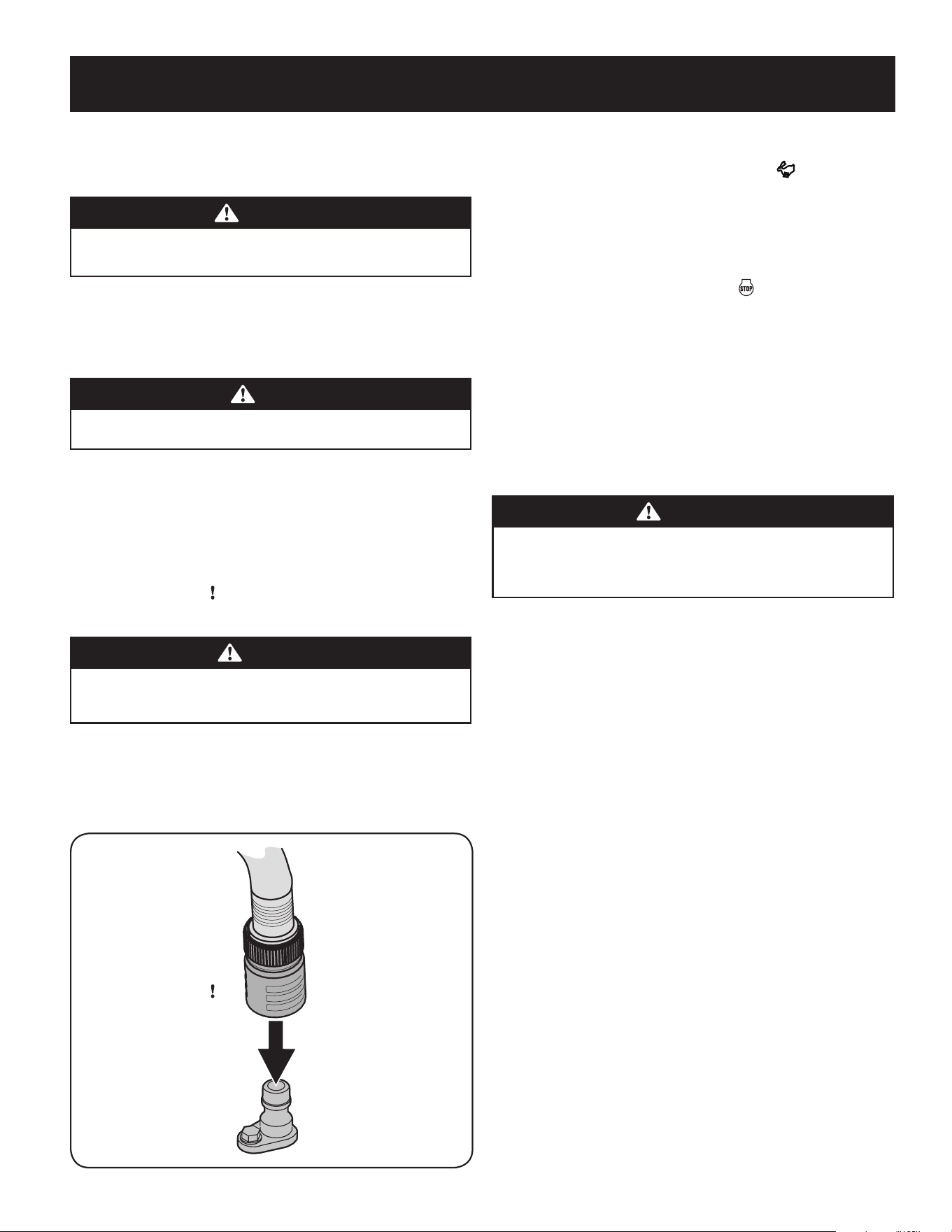
51
SERVICIO Y MANTENIMIENTO
calificadoNOTA: Este manual de operación cubre distintos modelos. Las
características del tractor pueden variar según los modelos. No todas las
características que se incluyen en este manual se aplican a todos los modelos de
tractor y la máquina que se ilustra aquí puede diferir de la suya.
ADVERTENCIA
Antes de realizar tareas de mantenimiento o reparaciones, desconecte la
PTO, ponga el freno de mano, apague el motor y retire la llave para evitar el
encendido accidental del motor.
Después de la operación del tractor Cuidado
Después de cada operación del tractor, los siguientes procedimientos deben ser
implementados para extender la vida útil de su tractor y garantizar condiciones
seguras de operación.
PELIGRO
El incumplimiento de estas recomendaciones puede provocar lesiones
graves a sí mismo oa otros y puede causar daños en el tractor.
Limpieza de la parte inferior del piso
Sistema de lavado de cubierta
La plataforma de su tractor está equipada con un puerto de agua sobre su superficie
como parte del sistema de lavado de la plataforma.
Utilice el Smart Jet para quitar los recortes de césped de la parte inferior de la
plataforma e impedir la acumulación de sustancias químicas corrosivas. Realice los
siguientes pasos DESPUÉS DE CADA CORTE DE CÉSPED:
1. Dirija el tractor a una zona nivelada y despejada del césped, que se encuentre
suficientemente cerca de una canilla de agua al alcance de la manguera del jardín.
PRECAUCIÓN
Asegúrese de que el canal de descarga del tractor NO ESTÉ ORIENTADO EN
LA DIRECCIÓN en que se encuentran las personas, la casa, el garaje, los
vehículos estacionados, etc.
2. Desconecte la toma de fuerza (PTO), aplique el freno de mano y detenga el motor.
3. Enrosque el acople de manguera (embalado con el Manual del Operador de
su tractor) en el extremo de la manguera de jardín.
44. Una el acople de la manguera al puerto de agua que se encuentra en la
superficie de la plataforma. Vea la Figura 15.
Figura 15
45. Abra el suministro de agua.
46. Mientras está sentado en la posición del operador del tractor, arranque el motor
y coloque la palanca del regulador en la posición FAST (velocidad rápida).
47. eva la PTO del tractor a la posición de activación (ON).
48. Permanezca en la posición del operador con la plataforma enganchada
durante dos minutos como mínimo, permitiendo que la parte inferior de la
plataforma de corte se lave a fondo.
49. Mueva la PTO del tractor a la posición de desactivación (OFF).
50. Gire la llave de encendido a la posición STOP (detención) para apagar el
motor del tractor.
51. Desconecte el agua y retire el acoplador de la manguera desde el puerto de
agua que se encuentra en la superficie de la plataforma.
52. NOTA: En las plataformas de 50 y 54 pulgadas hay dos puertos de agua; uno a
cada lado de la plataforma.
53. Después de limpiar la plataforma con el sistema Smart Jet, regrese a
la posición del operador y active la PTO. Mantenga la plataforma en
funcionamiento durante dos minutos por lo menos para permitir que se
seque totalmente la parte inferior de la misma.
Limpieza del tractor
ADVERTENCIA
Si el tractor ha sido recientemente funcionar, el motor, el silenciador y
las superficies metálicas circundantes estarán calientes y pueden causar
quemaduras en la piel. Deje que el motor se enfríe durante al menos cinco
minutos la precaución para evitar quemaduras.
Su tractor debe limpiarse después de cada uso y bajo ciertas condiciones, es decir,
condiciones secas y/o situaciones de picado, de limpieza adicional puede ser necesario.
Una de las mejores maneras de mantener su tractor funcionando de manera
eficiente y para reducir el riesgo de incendio es eliminar la acumulación de basura
con regularidad desde el tractor. Siga las recomendaciones a continuación y
póngase en contacto con su distribuidor autorizado con cualquier pregunta.
• Deje que la máquina se enfríe en un área abierta antes de la limpieza.
• No use agua en cualquier parte del tractor, excepto la parte inferior de la
plataforma de corte. Si lo hace, puede provocar daños en los rodamientos
para husillos del tractor, el sistema eléctrico y el motor, lo que lleva a fallas
prematuras. El uso de aire comprimido y / o soplador de hojas se ayudar a
mantener limpio el tractor.
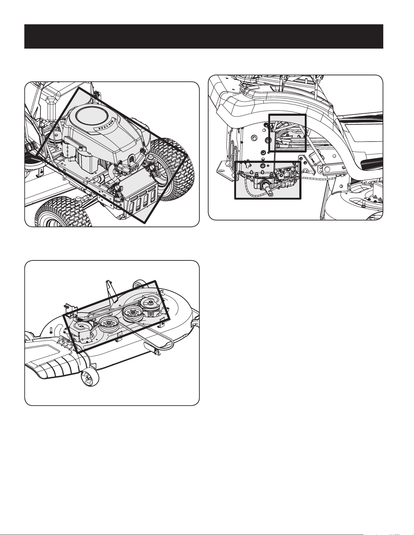
52
SERVICIO Y MANTENIMIENTO
• Clean bajo el capó. Colector de escape, alrededor de fusibles, todo el cableado y
arneses, tubo silenciador, escudo de silenciador, pantallas de admisión del motor y
las aletas de refrigeración, etc. Vea la Figura 16.
Figura 16
• Limpiar la parte superior de la plataforma de corte, bajo las sábanas de
husillo y área de la correa. Vea la Figura 17.
Figura 17
• Limpia alrededor y cerca de la transmisión, el eje y el área del ventilador. Vea
la Figura 18.
Rueda no muestra por claridad
Figura 18
• Los residuos pueden acumularse en cualquier lugar en el tractor, especialmente
en superficies horizontales. Limpieza adicional puede ser necesaria cuando la
siega en condiciones secas o cuando acolchado.
• Fugas de combustible / derrames, fugas de aceite / derrames y el exceso
de lubricación también pueden convertirse en sitios de colecciones de
escombros. Inmediata reparación y limpieza de derrames de aceite o
combustible puede ayudar a reducir los riesgos de incendio.
• Además de limpiar el tractor, antes de manejar y almacenar, no intente cortar
inusualmente alto (10 “o superior), la hierba seca (por ejemplo, pasto) o pilas
de hojas secas. Hierba u hojas en seco pueden ponerse en contacto con los
gases de escape del motor y / o acumularse en la plataforma de corte en un
peligro de incendio.
Almacenamiento del tractor
• Deje que la máquina se enfríe en un área abierta antes de guardarlo.
• No estacione el tractor cerca de materiales inflamables (madera, tela o productos
químicos) o cualquier llama abierta u otra fuente potencial de ignición (horno,
calentador de agua o cualquier otro tipo de calentador).
• Retire todos los materiales combustibles desde el tractor antes de guardarla.
Cajas de carga vacíos, recogedores de hierba y contenedores.
• Siempre cerrar el flujo de combustible cuando almacenar o transportar si
tractor está equipado con un cierre de combustible.
• Compruebe el sistema de combustible (líneas, el tanque, tapa y accesorios)
con frecuencia grietas o fugas. Reparación y limpiar como sea necesario.
Motor
Consulte el Manual del operador del motor para conocer todas las instrucciones y los
procedimientos de mantenimiento del motor a fin de controlar y agregar aceite. Consulte
la sección Cambio del aceite del motor que se incluye a continuación para conocer los
procedimientos y las instrucciones para el cambio de aceite.
NOTA: Si aparece el texto "LOW OIL" inmediatamente después de que el motor
arranca la presión de aceite puede estar baja. Esto es normal. Si la indicación de
nivel bajo de aceite persiste, pare el tractor inmediatamente y compruebe el nivel
de aceite del motor según las instrucciones del Manual del operador del motor.
NOTA: La función “Low Oil” (nivel bajo de aceite) solo funciona si el motor tiene un
interruptor de presión de aceite.
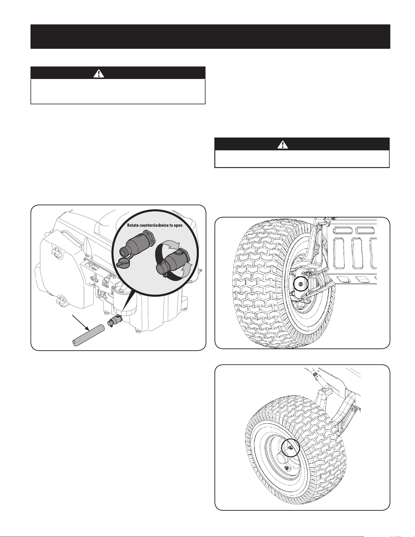
53
SERVICIO Y MANTENIMIENTO
Cambio de aceite del motor
ADVERTENCIA
Si el motor ha estado en funcionamiento recientemente, el motor, el silenciador
y las superficies metálicas circundantes estarán calientes y pueden causar
quemaduras en la piel. Tenga precaución para evitar quemaduras.
Para realizar el cambio de aceite, proceda de la siguiente manera:
1. Haga funcionar el motor por un período corto para calentar el aceite del motor. El
aceite fluirá mejor y limpiará las impurezas. Tenga cuidado y evite quemarse con el
aceite caliente.
2. Ubique el orificio de drenaje de aceite del lado izquierdo del motor.
3. Para recoger el aceite usado, coloque un recipiente adecuado para recolectar el
aceite, con al menos una capacidad de 2.5 cuartos de galón, debajo de la abertura
del tubo de drenaje de aceite. Retire el tapón de llenado de aceite/la varilla de
nivel de aceite del tubo de llenado.
4. Pop abrir la tapa protectora en el extremo de la válvula de drenaje del aceite para
exponer el orificio de drenaje. Véase la Figura 19.
OPENED
CLOSED
Claro tubo de drenaje de
aceite
Figura 19
5. Retire la tapa de llenado de aceite/varilla de medición del tubo de llenado
de aceite.
6. Empuje el tubo de drenaje de aceite claro (que acompaña a este manual)
dentro del orificio de drenaje de aceite. Coloque el extremo opuesto del
tubo en un recipiente de recolección de aceite adecuado con al menos una
capacidad de 2,5 cuartos para recoger el aceite usado.
7. El motor está equipado con un puerto de drenaje de giro y tracción. Girar la
válvula de drenaje de aceite ¼ de vuelta hacia la izquierda, a continuación,
tire hacia afuera para comenzar a drenar el aceite. Después de que el
petróleo ha terminado de drenaje, empuje el extremo de la válvula de
drenaje de aceite nuevo y vuelva a ¼ de vuelta en sentido horario para
asegurarlo en su lugar. Vuelva a tapar el extremo de la válvula de drenaje
para evitar que los desechos entren en el puerto de drenaje.
8. Para cargar el aceite, vuelva a colocar el tapón en el extremo del tubo y consulte el
manual del operador del motor para obtener instrucciones de recarga, el tipo de
aceite y cantidad.
NOTA: El mantenimiento, reparación o reemplazo de los dispositivos y sistemas
del control de emisiones, que corre por cuenta del cliente, puede realizarlo
cualquier establecimiento o individuo especializado en reparaciones de motores.
Los arreglos en garantía deben ser realizados por distribuidor autorizado.
Transmisión hidrostática
La transmisión hidrostática viene sellada de fábrica y no tiene mantenimiento alguno.
No se puede controlar el nivel de fluido ni se puede cambiar el líquido.
Ajuste punto muerto hidrostático
Para cambiar la correa de transmisión del tractor, se deben retirar varios componentes y
se necesitan herramientas especiales. Solicite a un distribuidor de servicio calificado que
realice el reemplazo de la correa de transmisión.
Lubricación
ADVERTENCIA
Antes de lubricar, reparar o inspeccionar, desactive la PTO, ponga el freno de
mano, pare el motor y retire la llave, para evitar el arranque accidental.
Ruedas delanteras
Cada uno de los ejes y llantas de las ruedas delanteras viene equipado con un dispositivo de
engrase. Consulte la Figura 20 para ver la ubicación del engrasador en los ejes y la Figura
21para ver la ubicación del engrasador en las llantas. Lubrique con una grasa multiuso No.
2 aplicada con una pistola de engrase cada 25 horas de funcionamiento del tractor.
Figura 20
Figura 21
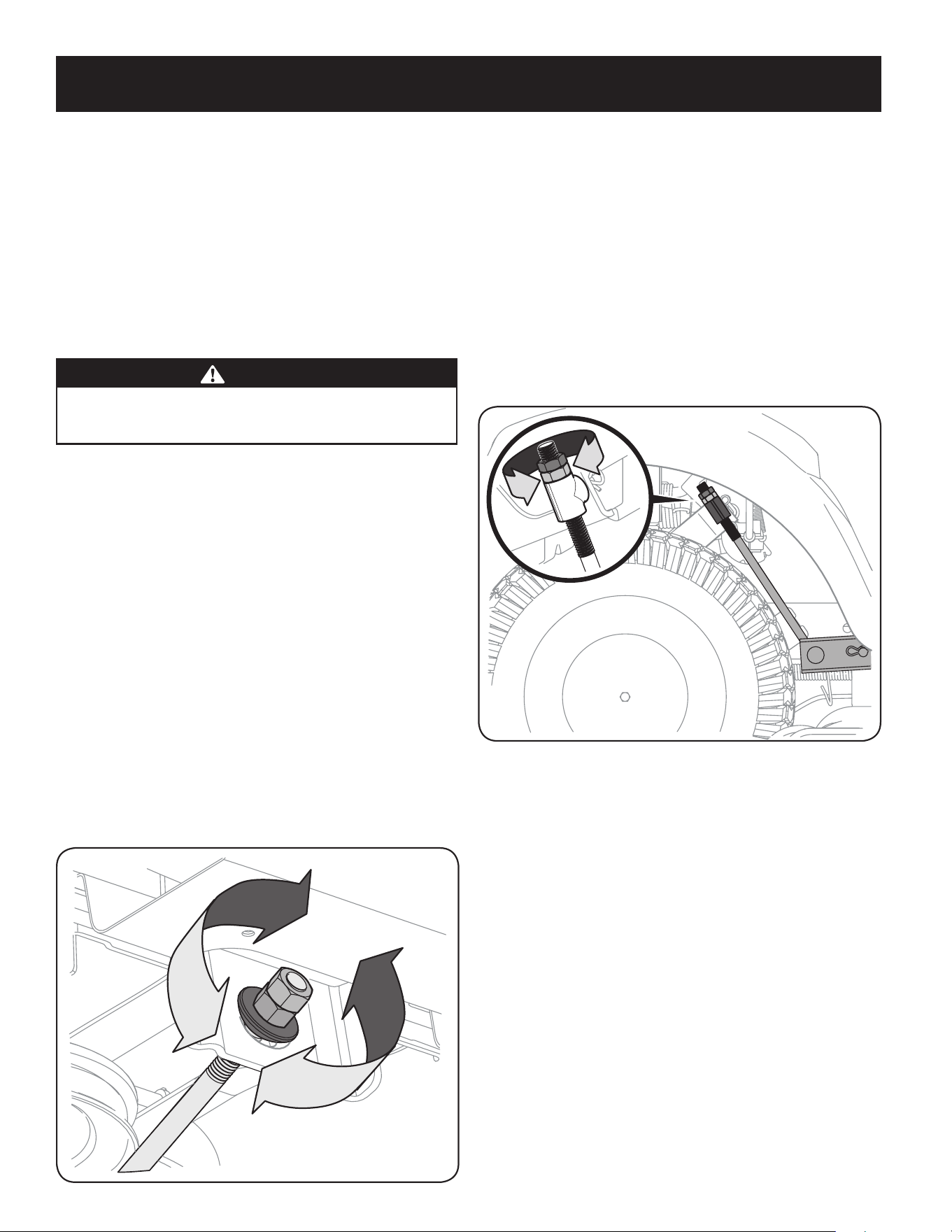
54
SERVICIO Y MANTENIMIENTO
Ruedas de la plataforma
Las ruedas de la plataforma están equipadas con dispositivo de engrase. Lubrique con una
grasa multiuso No. 2 aplicada con una pistola de engrase cada 25 horas de funcionamiento
del tractor.
Puntos de pivote y varillaje
Lubrique todos los puntos de pivote del sistema de impulsión, el freno de mano y el
varillaje de elevación al menos una vez por temporada con aceite ligero.
Nota: No es necesario engrasar la interfaz del engranaje del piñón de dirección /
sector. Hacerlo permitirá que se acumule suciedad y puede afectar el rendimiento
de la dirección.
Ajustes
ADVERTENCIA
Apague el motor, retire la llave de encendido y coloque el freno de mano antes
de realizar ajustes. Proteja sus manos utilizando guantes reforzados cuando
manipule las cuchillas.
NOTA: Controle la presión de neumáticos del tractor antes de realizar cualquier nivelación
de la plataforma. Consulte la sección Neumáticos en la página 11 para obtener información
sobre la presión de los neumáticos.
Ajuste de la plataforma
Nivelación de la plataforma (de adelante hacia atrás)
El frente de la plataforma de corte se apoya en una barra estabilizadora que se puede
ajustar para la nivelación frontal-posterior de la plataforma. El frente de la plataforma
debe estar entre 1⁄4”-3⁄8” más bajo que la parte posterior de la plataforma. De ser
necesario, realice un ajuste de la siguiente manera:
1. Con el tractor estacionado sobre una superficie firme y nivelada, coloque la
palanca de elevación de la plataforma en la posición media y gire la cuchilla más
cercana al canal de descarga para que quede perpendicular al tractor.
2. Mida la distancia desde la parte delantera de la punta de la cuchilla hasta el piso, y
desde la parte posterior de la punta de la cuchilla hasta el piso. La parte frontal de
la plataforma debe estar entre 1⁄4-3⁄8” más abajo que la parte posterior.
3. Determine la distancia aproximada necesaria para un ajuste adecuado y, de ser
necesario, proceda.
4. Para elevar el frente de la plataforma, afloje la tuerca exterior y apriete (rosca
hacia adentro) la tuerca contra el soporte de suspensión delantera. Consulte la
Figura 22. Cuando se logra el ajuste correcto, vuelva a apretar la tuerca externa
hasta 25-30 pies-libras.
Figura 22
5. Para bajar el frente de la plataforma, afloje la tuerca exterior y luego afloje (rosca
hacia afuera) la tuerca, alejándola del soporte de suspensión delantera. Consulte la
Figura 22. Cuando se logra el ajuste correcto, vuelva a apretar la tuerca externa.
Nivelación de la plataforma (de lado a lado)
Si la plataforma de corte estuviera realizando el corte de césped de forma despareja, puede
realizarse un ajuste lado a lado. De ser necesario, realice un ajuste de la siguiente manera:
1. Con el tractor estacionado sobre una superficie firme y nivelada, coloque la
palanca de elevación de la plataforma en la posición media y rote las dos cuchillas
para que queden perpendiculares al tractor.
2. Mida la distancia desde la parte externa de la punta de la cuchilla izquierda hasta
el piso, y desde la parte externa de la punta de la cuchilla derecha hasta el piso. Las
dos mediciones obtenidas deben ser iguales. Si no lo son, realice el siguiente paso.
3. Debajo de los guardabarros traseros dentro de las ruedas hay una varilla de ajuste
de elevación para cada lado de la plataforma. Vea la Figura 23.
Figura 23
4. Los ajustes de lado a lado menores se deben hacer usando principalmente la varilla
de ajuste izquierda.
5. Para elevar el lado izquierdo de la plataforma, afloje la tuerca superior del extremo
de la varilla de elevación, y gire la tuerca inferior a la derecha. Cuando logra el ajuste
correcto, apriete la tuerca superior para asegurarla en su lugar. Para bajar el lado
izquierdo de la plataforma, afloje la tuerca superior del extremo de la varilla de
elevación, luego gire la tuerca inferior a la izquierda. Cuando logra el ajuste correcto,
apriete la tuerca superior hasta 25-30 pies-libras para asegurarla en su lugar.
6. La plataforma se encuentra correctamente nivelada cuando las dos mediciones
que se tomaron anteriormente desde las puntas de las cuchillas son iguales.
Ajuste de la altura de la plataforma
La altura de la plataforma se puede ajustar para asegurar que la configuración de la
palanca de altura de la plataforma es precisa. Para ajustar la altura de la plataforma
proceda de la siguiente manera:
1. Con el tractor estacionado sobre una superficie firme y nivelada, coloque la
palanca de elevación de la plataforma en la posición más alta (4") y gire la cuchilla
más cercana al canal de descarga para que quede perpendicular al tractor.
2. Mida la distancia desde la parte externa de la punta de la cuchilla izquierda hasta
el piso, y desde la parte externa de la punta de la cuchilla derecha hasta el piso.
Las dos mediciones obtenidas deben ser 4 pulgadas. Si no lo son, realice el
siguiente paso.
3. Usando las varillas de elevación derecha e izquierda, eleve o baje la parte necesaria
de la plataforma hasta que ambos lados se encuentren a 4" del pavimento.

55
SERVICIO Y MANTENIMIENTO
Ajuste de las ruedas de la plataforma
ADVERTENCIA
Mantenga las manos y los pies alejados de la abertura de descarga de la
plataforma de corte.
NOTA: Las ruedas de la plataforma constituyen un mecanismo para el cuidado del césped
y no fueron diseñadas para soportar el peso de la plataforma de corte.
Las ruedas de la plataforma deben estar aproximadamente entre 1⁄4-1⁄2” por encima del
nivel del suelo cuando la plataforma se fija en el valor de altura deseado. Para obtener
instrucciones sobre cómo ajustar las ruedas de la plataforma consulte la sección Montaje
y Configuración.
Ajuste del asiento
Consulte en la sección Montaje y Configuración de este manual las instrucciones para el ajuste
del asiento.
ADVERTENCIA
Antes de hacer funcionar el tractor, compruebe que el asiento esté enganchado
en el tope del asiento. Ponga el freno de mano. Párese detrás de la máquina y
tire el asiento hacia atrás hasta que haga clic al calzar en su lugar.
Ajuste del freno de mano
Si el tractor no se detiene por completo cuando se presiona totalmente el pedal del freno,
o si las ruedas traseras del tractor siguen rodando con el freno de mano colocado (y la
válvula de descarga hidrostática abierta) el freno necesita ajustes. Consulte al distribuidor
de servicio autorizado para realizar un ajuste del freno.
Alineación de las ruedas
Si el tractor tira hacia un lado o está desalineado, podría ser necesario alinear las ruedas.
Lleve el tractor a un distribuidor de servicio autorizado para que le realicen una alineación
de ruedas correcta.
Servicio
Batería
ADVERTENCIA
Advertencia Proposición 65 de California: Los bornes de la batería y los accesorios
afines contienen plomo y compuestos de plomo, sustancias químicas que según
lo establecido por el Estado de California causan cáncer y daños en el sistema
reproductivo. Lávese las manos después de estar en contacto con estos componentes.
PRECAUCIÓN
Si extrae la batería, desconecte primero el cable NEGATIVO (negro) de su borne
y a continuación el cable POSITIVO (rojo). Cuando vuelva a instalar la batería,
conecte siempre primero el cable POSITIVO (rojo) a su borne, y a continuación el
cable NEGATIVO (negro).
La batería está sellada y no necesita mantenimiento. Los niveles de ácido no se pueden
controlar y no se puede agregar líquido.
• Siempre mantenga limpios y libres de acumulación de elementos corrosivos los cables y
los bornes de la batería.
• Después de limpiar la batería y los bornes, aplique una capa delgada de vaselina o
grasa a ambos bornes.
Arranque con cables de puente
ADVERTENCIA
Nunca arranque una batería dañada o congelada con conexiones en puente.
Asegúrese de que los vehículos no se toquen y los motores están apagados. No
permita que las pinzas de los cables se toquen.
1. Conecte el cable positivo (+) al borne positivo (+) de la batería descargada de
su tractor.
2. Conecte el otro extremo del cable al borne positivo (+) de la batería con carga.
3. Conecte el segundo cable negativo (–) al otro borne de la batería con carga.
4. Haga la conexión final al bloque del motor del tractor, alejado de la batería. Acople
a una parte sin pintura para asegurarse de que haya una buena conexión.
PRECAUCIÓN
Si la batería con carga está instalada en el vehículo (es decir automóvil, camión)
NO ponga en marcha el motor del vehículo cuando arranque su tractor con
conexiones en puente.
5. Arranque el tractor (según las instrucciones de la sección Funcionamiento de
este manual).
6. Retire los cables de arranque en orden inverso a la conexión.
Duración
ADVERTENCIA
Al cargarse, las baterías emiten un gas que puede causar explosiones. Cargue la
batería en un área bien ventilada y manténgala alejada de una llama expuesta o
piloto, como los de los calentadores de agua, calefactores de ambiente, hornos,
secadores de ropa y otros aparatos a gas.
PRECAUCIÓN
Cuando cargue la batería de su tractor, utilice únicamente un cargador diseñado para
baterías de plomo-ácido de 12V. Lea el manual del operador del cargador de la batería
antes de cargar la batería de su tractor. Siempre siga las instrucciones y tenga en
cuenta las advertencias.
Si su tractor no se ha utilizado durante un período de tiempo prolongado, cargue la batería
de la siguiente manera:
1. Ajuste el cargador de batería para que produzca un máximo de 10 amperios.
2. Si su cargador de batería es automático, cargue la batería hasta que el cargador
indique que se ha completado la carga. Si el cargador no es automático, cargue
durante ocho horas como mínimo.
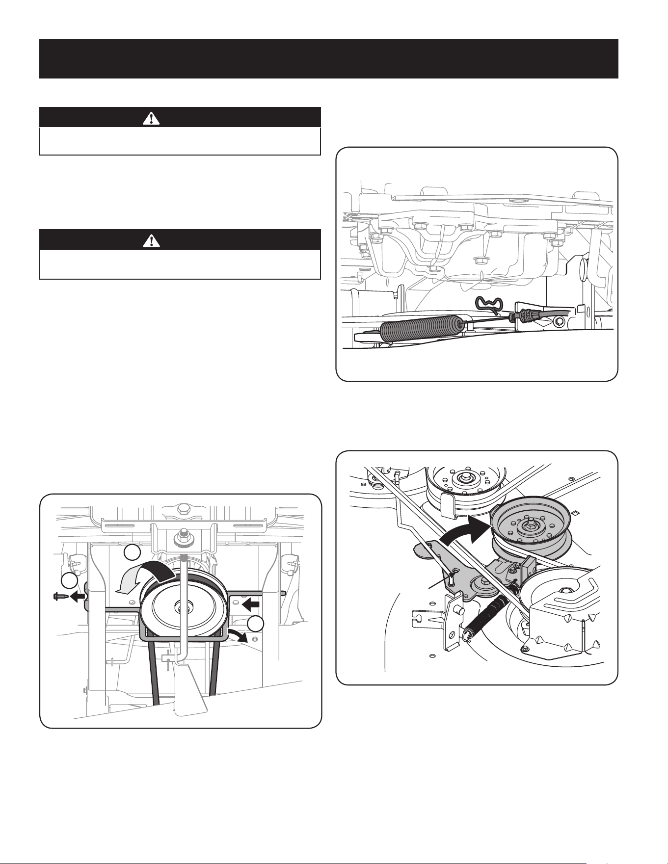
56
SERVICIO Y MANTENIMIENTO
Fusible
ADVERTENCIA
Antes de hacer el servicio, reparar o inspeccionar, siempre desactive la PTO, ponga
el freno de mano, pare el motor y retire la llave, para evitar el arranque accidental.
En el mazo de cables de su tractor está instalado un fusible de 20 amperios, para proteger
el sistema eléctrico del tractor de los daños causados por exceso de amperaje.
Si el sistema eléctrico no funciona, o el motor de su tractor no arranca, verifique que el
fusible no se haya quemado. Se encuentra ubicado debajo del asiento, conectado al
cable POSITIVO (rojo) que conduce a la batería.
PRECAUCIÓN
Utilice siempre un fusible de repuesto con la misma capacidad de amperaje que
el fusible quemado.
Relés e interruptores
Hay varios interruptores de seguridad en el sistema eléctrico. Si una función del sistema
de bloqueo de seguridad descripto antes no funciona adecuadamente, haga que el
distribuidor de servicio autorizado revise el sistema eléctrico.
Extracción de la plataforma de corte
42" Plataforma
1. Para extraer la plataforma de corte, proceda de la siguiente manera:
a. Coloque la PTO en la posición desactivada (OFF) y ponga el freno de
mano.
b. Baje la plataforma colocando la palanca de elevación de la
plataforma dentro de la muesca inferior del guardabarros derecho.
c. Saque el tornillo hexagonal que asegura la varilla guardapoleas del
motor al chasis. Vea la Figura 24.
3
4
8
Figura 24
d. Deslice la varilla hacia la derecha para sacarla. Vea la Figura 24.
NOTA: Cuando extraiga la varilla, actúe con precaución para evitar que se dañe el
arnés de cableado.
e. Extraiga el pasador de chaveta que sujeta el cable de la PTO al
soporte de la plataforma, tire hacia atrás del cable de la PTO, luego
deslícelo fuera del soporte y desenganche el resorte del soporte
intermedio. Vea la Figura 25.
Figura 25
f. Trabajando en el lado derecho del tractor, inserte una llave de
trinquete de 3⁄8”, regulada para ajustar, en el orificio cuadrado del
soporte intermedio. Vea la Figura 26.
Inserte la llave aquí
Figura 26
g. Continúe con el paso 2 en la página 58.
46” Plataforma
1. Para extraer la plataforma de corte, proceda de la siguiente manera:
a. Coloque la PTO en la posición desactivada (OFF) y ponga el freno de
mano.
b. Baje la plataforma colocando la palanca de elevación de la
plataforma dentro de la muesca inferior del guardabarros derecho.
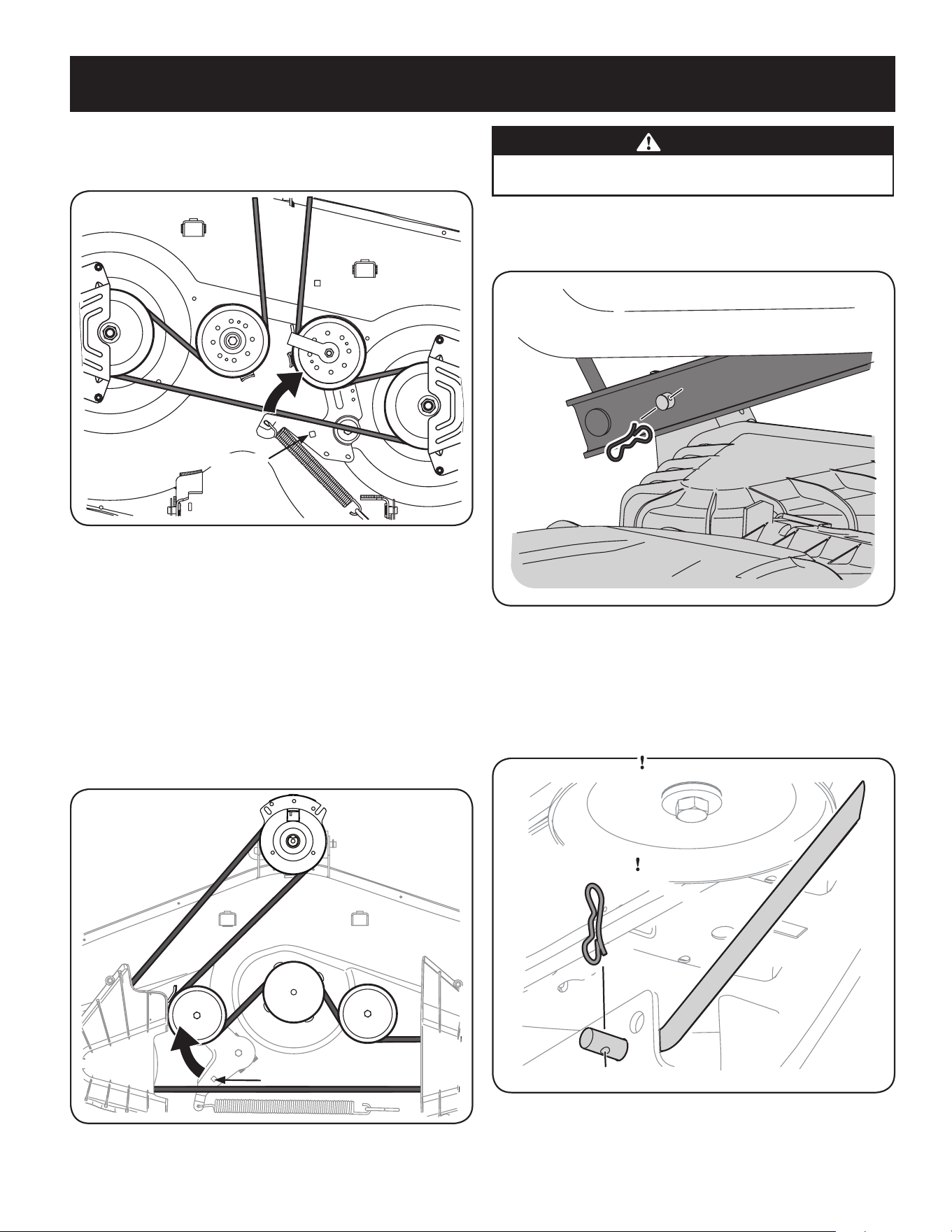
57
SERVICIO Y MANTENIMIENTO
c. Trabajando en el lado derecho del tractor, inserte una llave de trinquete
de 3⁄8”, regulada para ajustar, en el orificio cuadrado del soporte
intermedio. Vea la Figura 27.
Inserte la llave aquí
Figura 27
d. Continúe con el paso 2 en la página 58.
54” Plataforma
1. Para extraer la plataforma de corte, proceda de la siguiente manera:
a. Coloque la PTO en la posición desactivada (OFF) y ponga el freno de
mano.
b. Baje la plataforma colocando la palanca de elevación de la
plataforma dentro de la muesca inferior del guardabarros derecho.
c. Trabajando en el lado derecho del tractor, inserte una llave de trinquete
de 3⁄8”, regulada para ajustar, en el orificio cuadrado del soporte
intermedio. Vea la Figura 28.
Inserte la llave aquí
Figura 28
d. Continúe con el paso 2 en la página 58.
2. Utilice la llave para girar hacia adelante la polea de transmisión de la plataforma.
Vea la Figura 28.
ADVERTENCIA
Evite las lesiones por compresión. Al instalar la correa, no coloque nunca los
dedos en el resorte intermedio o entre la correa y una polea.
3. Extraiga con cuidado la correa de alrededor de la polea de la PTO.
4. Mirando hacia la plataforma de corte desde el lado izquierdo del tractor, ubique el
pasador de chaveta en el lado posterior izquierdo de la plataforma. Vea la Figura 29.
Figura 29
5. Retire el pasador y saque el pasador de la plataforma del brazo de elevación de la
misma. Vea la Figura 29.
6. Repita los pasos anteriores del lado derecho del tractor.
7. Tire del pasador de chaveta hacia afuera de la varilla de elevación delantera de la
plataforma que la sujeta a la plataforma. Consulte la Figura 30. Deslice la varilla de
elevación de la plataforma fuera del soporte de suspensión frontal.
Figura 30
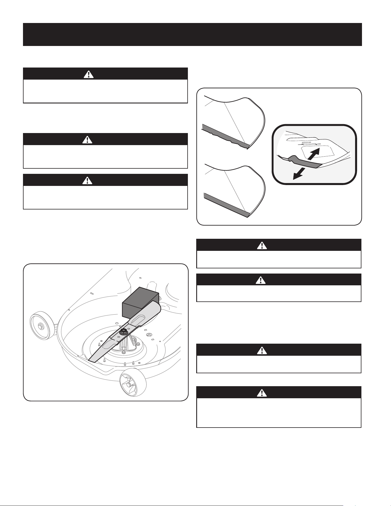
58
SERVICIO Y MANTENIMIENTO
8. Mueva la palanca de elevación de la plataforma a la muesca superior para levantar
el elevador de la plataforma y sacarlo del camino.
PRECAUCIÓN
Hay cierta tensión de los resortes debido al peso de la plataforma. Al retirar el varillaje de
elevación de la plataforma, la tensión de los resortes pasará de la plataforma a la manija
de elevación de plataforma y retrocederá a su posición original.
9. Deslice suavemente la plataforma de corte hacia afuera desde la parte inferior
del tractor.
Cuchillas de corte
ADVERTENCIA
Apague el motor y extraiga la llave de contacto antes de retirar las cuchillas
de corte para afilarlas o reemplazarlas. Proteja sus manos utilizando guantes
reforzados cuando sujete las cuchillas.
ADVERTENCIA
Inspeccione periódicamente la cuchilla y/o el husillo en busca de rajaduras
o daños, especialmente después de golpear un objeto extraño. No opere la
máquina hasta después de haber reemplazado los componentes dañados.
Para retirar las cuchillas, haga lo siguiente.
1. Retire la plataforma desde abajo del tractor, (consulte la sección Retiro de la
plataforma de corte anteriormente en esta sección) luego voltee con delicadeza la
plataforma para visualizar su parte inferior.
2. Coloque un bloque de madera entre el deflector del alojamiento de la plataforma y
la cuchilla de corte para que actúe como estabilizador. Vea la Figura 31.
Figura 31
3. Extraiga la tuerca de brida hexagonal que asegura la cuchilla al montaje del
husillo. Vea la Figura 31.
4. Para afilar las cuchillas de corte de forma adecuada, extraiga cantidades
iguales de metal de ambos extremos de las cuchillas a lo largo de los bordes
cortantes, paralelo al borde de caída y a un ángulo de 25° a 30°. Afile siempre
cada borde de las cuchillas de corte de forma pareja para mantener un
equilibrio adecuado entre las mismas. Vea la Figura 32.
Figura 32
PRECAUCIÓN
Si el borde de corte de la cuchilla ha sido afilado previamente o si existe una
separación de metal, reemplace las cuchillas por otras nuevas.
ADVERTENCIA
Una cuchilla mal equilibrada causará exceso de vibración y puede dañar el
tractor y/o causar lesiones.
5. Pruebe el equilibrio de la cuchilla usando un compensador de cuchillas. Afile el
metal del lado pesado hasta que quede bien equilibrada.
NOTA: Cuando reemplace la cuchilla, asegúrese de instalarla con el lado marcado
“Bottom” (inferior) (o con el lado que posee un número de pieza estampado)
mirando al piso cuando la cortadora de césped está en posición de operación.
PRECAUCIÓN
Utilice una llave de torsión para ajustar la tuerca de brida hexagonal del husillo de
la cuchilla entre 70 pies-libras y 90 pies-libras.
Cambio de la correa de la plataforma
ADVERTENCIA
Las correas en V de su tractor están especialmente diseñadas para activar y
desactivar con seguridad. Una correa de repuesto (no del fabricante original)
puede ser peligrosa por no desactivar completamente. Para una máquina que
funcione correctamente, utilice correas aprobadas por la fábrica.
Todas las correas del tractor se desgastan y se las debe cambiar si presentan signos de
desgaste. Para cambiar o reemplazar la correa de la plataforma de su tractor, proceda de la
siguiente manera:
1. Saque la plataforma como se indicó anteriormente en esta sección en Extracción de la
plataforma de corte.
NOTA: En algunas plataformas puede ser necesario retirar las cubiertas de los
husillos para sacar y/o instalar la correa nueva. Para retirar las cubiertas de los
husillos, saque los tornillos que los sujetan a la plataforma.
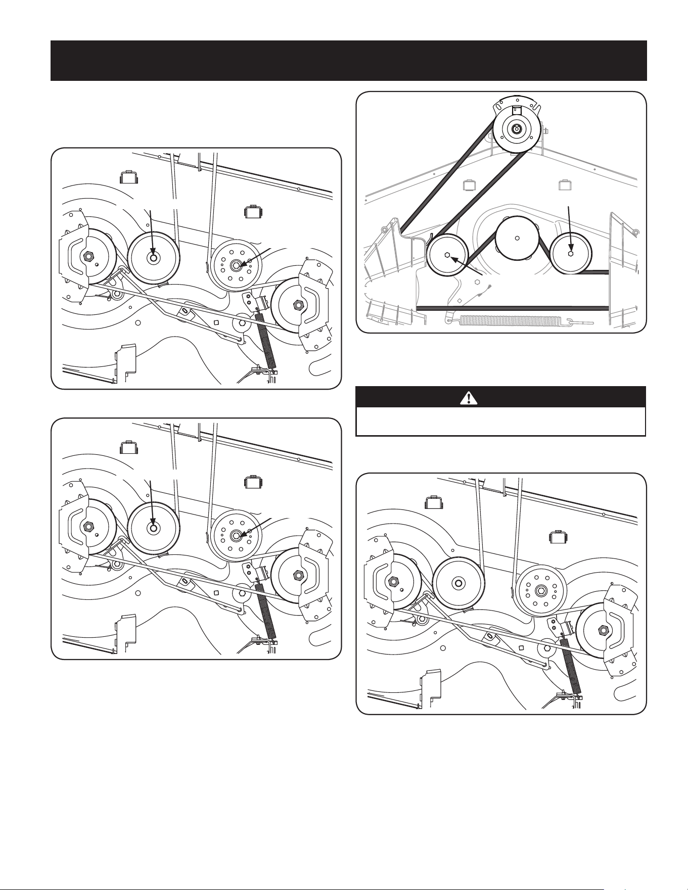
59
SERVICIO Y MANTENIMIENTO
2. Afloje , pero no quite la tuerca de seguridad con brida de la polea tensora izquierda
de 54" Las cubiertas y la polea loca adecuado para 42" y 46" de skate . Vea la Figura
33 para 42" Cubiertas, Figura 34 para 46" Las cubiertas y la Figura 35 para 54"
Cubiertas
Tornillo hexagonal
Tuerca de seguridad
con brida
Figura 33
Tornillo hexagonal
Tuerca de seguridad
con brida
Figura 34
Tornillo hexagonal
Tuerca de seguridad con brida
Figura 35
3. Saque con cuidado la correa de alrededor de las poleas locas y las poleas de
los husillos.
ADVERTENCIA
Evite las lesiones por compresión. Al extraer la correa, no coloque nunca los
dedos en el resorte intermedio o entre la correa y una polea.
4. Coloque la correa nueva como se muestra en la Figura 36 para 42" Cubiertas,
Figura 37 para 46" Las cubiertas y la Figura 38 para 54" de skate .
Figura 36
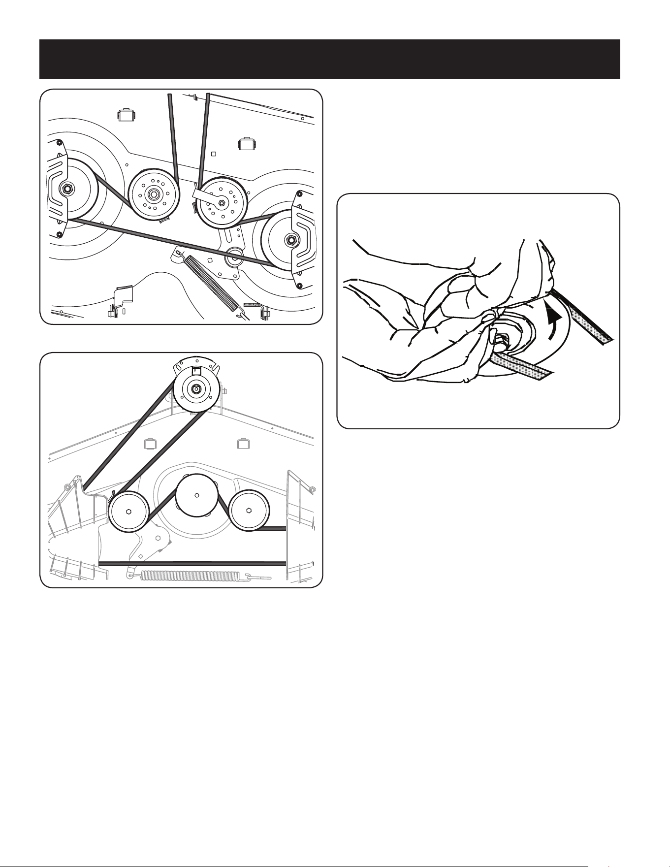
60
SERVICIO Y MANTENIMIENTO
Figura 37
Figura 38
NOTA: Use una llave de trinquete de 3⁄8” de pulgada como se indica en pasos
anteriores para colocar la correa nueva.
5. Vuelva a ajustar las poleas locas.
6. Vuelva a montar las cubiertas de los husillos se fueron retiradas después del
paso 1.
7. Reinstale la plataforma, comprobando que la correa se ha pasado alrededor de las
poleas como se indica.
8. Tire del lado derecho de la correa y coloque el lado V angosto de la correa en la
polea de la PTO. Vea la Figura 39.
Figura 39
9. Mientras sostiene la correa y la polea juntas, rote la polea hacia la izquierda. Siga
sosteniendo y rotando la polea y la correa hasta que la correa se enrolle totalmente
en la polea de la PTO.
Cambio de la correa de transmisión
Para cambiar la correa de transmisión del tractor, se deben retirar varios componentes y
se necesitan herramientas especiales. Solicite a un distribuidor de servicio calificado que
realice el reemplazo de la correa de transmisión.

61
ALMACENAMIENTO FUERA DE TEMPORADA
PREPARACIÓN DEL MOTOR
IMPORTANTE: El combustible que queda en el tanque cuando hace
calor se deteriora y ocasiona graves problemas de encendido.
PRECAUCIÓN
La no utilización de un aditivo de combustible de estabilización o
totalmente en marcha el motor hasta que se quedan sin combustible
antes de su almacenamiento fuera de temporada puede resultar
en daños al carburador del motor. Daños posteriores no estarían
cubiertos por la garantía del fabricante.
Motores se almacena entre 30 y 90 días deben ser tratados con un
estabilizador de gasolina y los motores almacenados más de 90 días
es necesario drenar el combustible para evitar el deterioro y la goma
de la formación en el sistema de combustible o en las partes esen-
ciales del carburador. Si la gasolina en el motor se deteriora durante
el almacenamiento, puede ser necesario tener el carburador, y otros
componentes del sistema de combustible, la reparación o sustitución.
Para evitar que se formen depósitos de goma en el interior del
carburador del motor y causar un posible mal funcionamiento del mo-
tor, el sistema de combustible debe ser vaciado completamente, o la
gasolina debe ser tratado con un estabilizador para evitar su deterioro.
1. Si utiliza un estabilizador de combustible:
a. Lea las instrucciones y recomendaciones del fabricante del
producto.
b. Agregue la cantidad correcta de estabilizador para la
capacidad del sistema de combustible a gasolina limpia y
nueva.
c. Llene el depósito de combustible con combustible tratado
y haga funcionar el motor 2-3 minutos para estabilizar el
combustible dentro del carburador.
2. Cuando vacíe el sistema de combustible:
a. No drene el combustible cuando el motor está caliente.
Permita que el motor se enfríe bien. Drene el combustible
dentro de un recipiente aprobado y al aire libre, lejos de
cualquier llama expuesta.
b. Drene un gran volumen de combustible desde el depósito,
desconectando la línea de combustible del filtro de combus-
tible en línea que se encuentra cerca del motor.
ADVERTENCIA
La gasolina es sumamente inflamable y puede ser explosiva en ciertas
condiciones. Vacíe la antes de almacenar el equipo durante períodos
prolongados. Drene el combustible únicamente dentro de un
recipiente aprobado y al aire libre, lejos de cualquier llama expuesta.
Deje que el motor se enfríe. Antes de drenar el combustible, apague
cigarrillos, cigarros, pipas y otras fuentes de combustión. Vacíe la
gasolina en un área bien ventilada, lejos de cualquier fuente de llama
o chispas, incluído cualquier artefacto con luz piloto. Almacene la
gasolina en un recipiente aprobado, en un lugar seguro.
c. Vuelva a contectar la línea de combustible y haga funcionar
el motor hasta que comience a fallar, use entonces el
cebador para mantener el motor en marcha hasta agotar
todo el combustible del carburador.
d. Vuelva a desconectar la línea de combustible y drene la
gasolina restante en el sistema.
ADVERTENCIA
La gasolina es una sustancia tóxica. Elimine la gasolina
adecuadamente. Comuníquese con las autoridades locales para
averiguar cuáles son los métodos adecuados para eliminar la gasolina.
3. Extraiga la bujía y vierta una (1) onza de aceite para motor por el
orificio de la bujía en el cilindro. Haga girar el motor varias veces
para distribuir el aceite. Vuelva a colocar la bujía.
4. Limpie los residuos de todo motor, con protección para los dedos,
y debajo, alrededor y detrás del silenciador. Retocar la pintura
dañada, y las áreas otro pelaje que pueden oxidarse con una
película delgada de aceite.
5. Conservar en un lugar limpio, seco y bien ventilado lejos de
cualquier aparato que funciona con una llama o luz piloto, como
un horno, calentador de agua o secadora de ropa. También evitar
cualquier área con un motor eléctrico que produzca chispas, o
donde las herramientas eléctricas son operados.
6. Si es posible, evitar las zonas de almacenamiento con alta
humedad, ya que promueve la oxidación y la corrosión.
7. Mantener el nivel de motor de almacenamiento. Inclinación puede
provocar fugas de aceite o combustible.
EL DRENAJE DE LOS COMBUSTIBLES
1. Localice el filtro de combustible, que se encuentra en el lado
izquierdo del motor, y puede ser conectado al motor con una
correa de empate.
2. Cortar la correa de la corbata, si está presente, entonces emer-
gente en la abrazadera en línea en el filtro de combustible con un
par de alicates, deslice la abrazadera de la línea de combustible.
3. Quite la línea de combustible en la línea y la fuga de combustible
en un recipiente aprobado.
PREPARACIÓN DE LA TRACTOR DE CÉSPED
1. Limpie y lubrique la tractor como se describe en las instrucciones
de lubricación.
2. No utilice una lavadora a presión ni una manguera de jardín para
limpiar su unidad.
3. Almacene la tractor en una zona limpia y seca. No la almacene
cerca de materiales corrosivos como por ejemplo fertilizantes.
ELIMINACIÓN DE ALMACENAMIENTO
1. Revise su motor como se describe en la sección de la Asamblea
de este manual.
2. Si el combustible fue drenado durante la preparación de almace-
namiento, llene el tanque con gasolina fresca. Si usted mantiene
un contenedor de gasolina para repostar, asegúrese de que
contiene sólo combustible fresco. La gasolina se oxida y deteriora
con el tiempo, causando problemas de arranque.
3. Si el cilindro fue recubierta con aceite durante la preparación de
almacenamiento, el motor de humo al arrancar. Esto es normal.
ADVERTENCIA
Nunca almacene tractor de césped con combustible en el tanque en un espacio cerrado o en áreas con poca ventilación, donde los gases del
combustible puedan alcanzar el fuego, chispas o una luz piloto como la que tienen algunos hornos, calentadores de agua, secadores de ropa
o algún otro dispositivo a gas.

62
SOLUCIÓN DE PROBLEMAS
Esta sección aborda problemas menores de servicio. Para ubicar el centro de servicio autorizado más cercano o para programar el servicio, llame 1-888-
331-4569.
ADVERTENCIA
Antes de realizar cualquier tipo de mantenimiento o servicio, desactive todos los controles y detenga el motor. Espere a que se detengan
completamente todas las piezas móviles. Desconecte el cable de la bujía y póngalo haciendo masa contra el motor para evitar que se encienda
accidentalmente. Utilice siempre anteojos de seguridad durante el funcionamiento o mientras ajusta o repara este equipo.
Problema Causa Solución
El motor no arranca 1. Manija de toma de fuerza (PTO)/activación de cuchilla
activada.
2. No está colocado el freno de mano.
3. Se ha desconectado el cable de bujía.
4. La palanca de control del acelerador no está en la
posición de arranque correcta.
5. El tanque de combustible está vacío o el combustible
se ha echado a perder.
6. La línea del combustible está bloqueada.
7. La bujía no funciona correctamente.
8. Motor ahogado.
9. Fusible(s) quemado(s).
1. Coloque la manija en la posición de desactivación (OFF).
2. Ponga el freno de mano.
3. Conecte el cable a la bujía.
4. Mueva la palanca del regulador a la posición FAST (velocidad
rápida).
5. Llene el depósito con gasolina limpia y nueva (que tenga menos
de 30 días).
6. Vuelva a colocar la línea de combustible. Comuníquese con
distribuidor de servicio calificado. Reemplace el filtro de
combustible. Consulte la sección Servicio y Mantenimiento.
7. Limpie, ajuste la separación, o cambie la bujía.
8. Arranque el motor con el acelerador en posición FAST (velocidad
rápida).
9. Reemplace el fusible.
El motor funciona de manera errática 1. La unidad está funcionando con el cebador activado.
2. Los cables de bujía están flojos.
3. La línea del combustible está tapada o el combustible
se ha echado a perder.
4. La ventilación de la tapa del combustible está
obstruida.
5. Hay agua o suciedad en el sistema de combustible.
6. El depurador de aire está sucio.
1. Compruebe que el cebador eléctrico funcione. Comuníquese con
distribuidor de servicio calificado.
2. Conecte y ajuste los cables de la bujía.
3. Vuelva a colocar la línea de combustible. Comuníquese con
distribuidor de servicio calificado. Llene el tanque con gasolina
limpia y nueva y reemplace el filtro de combustible. Consulte la
sección Servicio y Mantenimiento.
4. Destape la ventilación o reemplace la tapa si está dañada.
5. Vacíe el tanque de combustible. Recargue el tanque con
gasolina limpia y nueva. Consulte la sección Servicio y
Mantenimiento.
6. Limpie o reemplace el elemento de papel del depurador de aire o
limpie el prefiltro de espuma.
El motor recalienta 1. El nivel de aceite del motor está bajo.
2. Flujo de aire restringido
1. Llene el motor con cantidad y tipo de aceite adecuados.
2. Elimine los recortes de césped y los desechos de alrededor de
las aletas de enfriamiento del motor y de la carcasa del soplador.
El motor vacila a altas revoluciones 1. Poca separación de los electrodos de la bujía 1. Extraiga la bujía y regule la separación.
El motor funciona mal en
marcha lenta
1. La bujía de encendido está sucia
2. El depurador de aire está sucio.
1. Extraiga la bujía y regule la separación.
2. Limpie o reemplace el elemento del depurador de aire y/o limpie
el prefiltro.
Vibración excesiva 1. Cuchillas de corte flojas o descentradas.
2. Cuchilla dañada, desafilada o doblada.
1. Apriete la cuchilla y el husillo. Equilibre la cuchilla.
2. Reemplace la cuchilla.
La cortadora de césped
no procesa los recortes
como abono
1. La velocidad del motor es demasiado lenta.
2. Pasto mojado.
3. Césped demasiado alto.
4. La cuchilla de la cortadora no está afilada.
1. Coloque el control del acelerador en la posición FAST (velocidad
rápida, representada por una liebre).
2. No procese abono cuando el pasto está mojado.
3. Corte una vez con altura de corte elevada y luego vuelva a cortar
el césped a la altura deseada, o haga una pasada de corte más
angosta.
4. Afile o cambie la cuchilla.
Corte desigual 1. La plataforma no está correctamente nivelada.
2. Cuchilla desafilada.
3. Presión de neumáticos desigual.
1. Haga un ajuste de la plataforma de lado a lado.
2. Afile o cambie la cuchilla.
3. Verifique la presión de los cuatro neumáticos.

NOTAS
63

Product Manufactured by (Producto fabricado por): MTD LLC, P.O. BOX 361131 CLEVELAND, OHIO 44136-0019
CRAFTSMAN® is a registered trademark of Stanley Black & Decker, Inc., used under license.
CRAFTSMAN® es una marca registrada de Stanley Black & Decker, Inc., utilizada bajo licencia.
© 2018 CRAFTSMAN U.S. & Canada Only
CRAFTSMAN.com
