INSTRUCTION MANUAL Lawn Tractor
ASSEMBLY
NOTE: All references in this manual to the left or right side and front or back of the tractor are from the operating position only. Exceptions, if any, will be specified.
Tractor Preparation
Manually Moving the Tractor
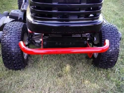
- Engage the transmission bypass rod to move the tractor manually without starting it. The transmission bypass rod is located on the rear of the tractor, on the frame. Engage the bypass rod by pulling out.
- Disengage the bypass rod by pushing the rod back in after moving the tractor.
Install Operator’s Seat (If necessary): To install the seat proceed as follows: NOTE: The seat is shipped with the seat switch and seat pan attached.
- Cut any straps securing the seat assembly to the tractor. Remove any packing material. NOTE: Be careful not to cut the wiring harness connecting the seat and the seat switch.
- Remove the two shoulder screws and flange lock nuts in the seat pan
- Rotate the seat into position and secure the seat into place with the previously removed shoulder screws and flange lock nuts. Be careful not to crimp or damage the wire harness while installing the seat
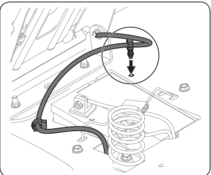
- Using the harness clip attached to the harness, secure the excess wire to the fender by snapping the harness clip in place
Lower Deck Discharge Chute Deflector
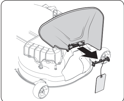
WARNING: Never operate the mower deck without the chute deflector installed and in the down position.
Check the mower deck for a shipping brace that may be holding the chute deflector upward for shipment. If the brace is present, it must be removed before operating the tractor. Holding the chute deflector fully upward, remove the shipping brace. Lower the chute deflector.
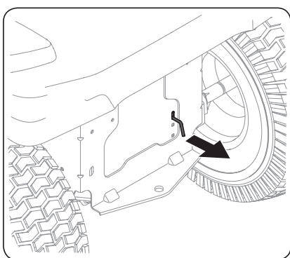
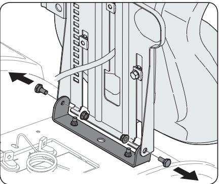
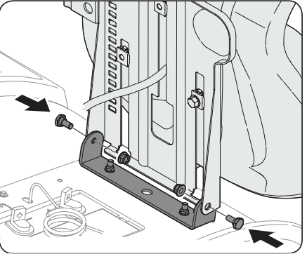
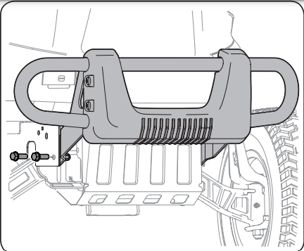
Installing the Front Bumper (If equipped):The hardware for attaching the front bumper is shipped installed into the bumper.
- Remove the four hex screws from the bumper.
- Position the bumper brackets to the inside of the tractor’s frame and secure it in place with the four hex flange screws
Adjusting the Seat
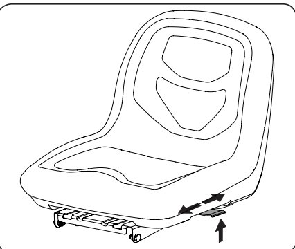
- To adjust the position of the seat, lift the seat adjustment lever up. Slide the seat forward or rearward to the desired position; then release the adjustment lever. Make sure seat is locked into position before operating the tractor
Checking Tire Pressure
- WARNING: Equal tire pressure should be maintained at all times. Refer to the tire sidewall for proper pressure.
- The tires on your tractor may be over-inflated for shipping purposes. Reduce the tire pressure before operating the tractor.
- The recommended operating tire pressure is 14 psi for the front and rear tires
- NOTE: Equal tire pressure is critical for level cutting deck performance
Connecting the Battery Cables
WARNING: CALIFORNIA PROPOSITION 65 WARNING: Battery posts, terminals, and related accessories contain lead and lead compounds, chemicals known to the State of California to cause cancer and reproductive harm. Wash hands after handling.
CAUTION: When attaching battery cables, always connect the POSITIVE (Red) wire to its terminal first, followed by the NEGATIVE (Black) wire. For shipping reasons, both battery cables on your equipment may have been left disconnected from the terminals at the factory. To connect the battery cables, proceed as follows:
NOTE: The positive battery terminal is marked Pos. (+). The negative battery terminal is marked Neg. (–).
NOTE: If the positive battery cable is already attached, skip ahead to step 2.
1. Remove the plastic cover, if present, from the positive battery terminal and attach the red cable to the positive battery terminal (+) with the bolt and hex nut
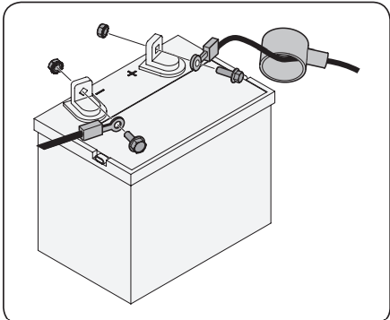
2. Remove the plastic cover, if present, from the negative battery terminal and attach the black cable to the negative battery terminal (–) with the bolt and hex nut
3. Position the red rubber boot over the positive battery terminal to help protect it from corrosion.
NOTE: If the battery is put into service after the date shown on top/side of battery, charge the battery as instructed in the Service section your Operator’s Manual prior to operating the tractor
Setting the Deck Wheels
WARNING: Keep hands and feet away from the discharge opening of the cutting deck.
NOTE: The deck wheels are an anti-scalp feature of the deck and are not designed to support the weight of the cutting deck.
Move the tractor on a firm and level surface, preferably pavement, and proceed as follows:
- Check the tire pressure, make sure the pressure is correct and equal on all tires.
- Make sure the deck is level, both front-to-back and side-to-side. See the Maintenance & Adjustments section for deck leveling information and instructions.
- Select the height position of the cutting deck by placing the deck lift lever in the normally desired mowing height setting.
- Check the wheels for contact or excessive clearance with the surface below. The deck wheels should have between ¼” and ½” clearance above the ground. Proceed as follows to adjust the wheels:
- Raise the deck lift handle to its highest setting.
- Remove the front and rear deck wheels by removing the flange lock nuts and shoulder bolts that secure them to the deck
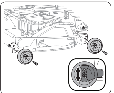
- Place the deck lift lever in the desired mowing height setting.
- Reinsert the shoulder bolt (with each deck wheel) into the index hole that leaves approximately ½-inch between the bottom of the wheel and the pavement. Tighten the flange lock nut and shoulder bolt to between 25-30 ft-lbs using a torque wrench.
NOTE: Refer to Adjusting the Deck in the Maintenance & Adjustments section of this manual for more detailed instructions regarding various deck adjustments.
Gas and Oil
Fuel Recommendations: Use automotive gasoline (unleaded or low leaded to minimize combustion chamber deposits) with a minimum of 87 octane. Gasoline with up to 10% ethanol or 15% MTBE (Methyl Tertiary Butyl Ether) can be used. Never use an oil/gasoline mixture or dirty gasoline. Avoid getting dirt, dust, or water in the fuel tank. DO NOT use E85 gasoline.
- Refuel in a well-ventilated area with the engine stopped. Do not smoke or allow flames or sparks in the area where the engine is refueled or where gasoline is stored.
- Do not overfill the fuel tank. After refueling, make sure the tank cap is closed properly and securely.
- Be careful not to spill fuel when refueling. Spilled fuel or fuel vapor may ignite. If any fuel is spilled, make sure the area is dry before starting the engine.
- Avoid repeated or prolonged contact with skin or breathing of vapor.
Adding Fuel
WARNING: Use extreme care when handling gasoline. Gasoline is extremely flammable and the vapors are explosive. Never fuel the riding mower indoors or while the engine is hot or running. Extinguish cigarettes, cigars, pipes and other sources of ignition.
- Be sure engine is outdoors and in a well-ventilated area.
- Clean area around the fuel fill cap and remove the fuel fill cap.
- Using an approved red GASOLINE container, add fuel slowly, being careful to avoid spilling.
- Fill the tank until the fuel reaches the bottom of the fuel tank neck.
- Replace the fuel cap and tighten securely. Wipe up spilled fuel before starting engine. If fuel is spilled DO NOT start engine. Move riding mower away from area of spillage. Avoid creating any source of ignition until fuel vapors are gone.
Checking and Adding Oil
- Your riding mower is shipped with oil in the engine. However, you MUST check the oil level before operating. Check and add the oil as instructed in your Engine Operator’s Manual.
- CAUTION: Always check the engine oil level before each use as instructed in the engine operator’s manual. Add oil as necessary. Failure to do so may result in serious damage to your engine.
Smart Lawn App Bluetooth® Activation (If Equipped)

- Take command of your lawn care with the Bluetooth® enabled Smart Lawn App from Craftsman. Maintenance tips, weather tracking and more — everything you need to keep the best yard on the block is now in one place. Smart Lawn also provides step-by-step instructions and video tutorials to show you how to keep your riding mower running right. Plus, you can order the parts you need directly from the app. The app also tracks the charge of your riding mower battery, as well as the state of other key replacement components like oil, blade and air filter.
- Connect your Bluetooth® enabled riding mower by downloading the FREE Craftsman Smart Lawn App to begin using all of the new connectivity features of your Craftsman rider! Download it for FREE from the App Store or Google Play (works with devices running iOS 9, Android 4.4 and later versions).
- First, set your smartphone Bluetooth® setting to the ‘ON’ position. Next, you will need to create your account. The app will prompt you to enter your riding mower’s model number and serial number. Next it will attempt to connect with the riding mower via Bluetooth®.
- In order to sync your phone to the riding mower, start your mower so the engine is running, keep your device within 150 feet of the mower, and make sure your mower’s battery is fully charged. Remember to turn the key to the ’OFF’ position after you connect so as not to drain the battery charge (if not running the riding mower)
OPERATION
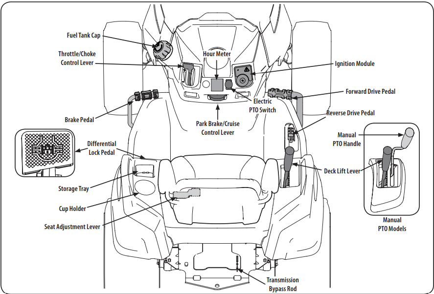
Now that you have set up your riding mower, it’s important to become acquainted with its controls and features. Refer to Differential
NOTE: This Operator’s Manual covers several models. Tractor features may vary by model. Not all features in this manual are applicable to all tractor models and the tractor depicted may differ from yours.
NOTE: References to LEFT, RIGHT, FRONT, and REAR indicate that position on the tractor when facing forward while seated in the operator’s seat.
WARNING: Read and follow all safety rules and instructions in this manual, including the entire Operation section, before attempting to operate this machine. Failure to comply with all safety rules and instructions may result in personal injury.
- Forward Drive Pedal: The forward drive pedal is located on the right side of the machine, along the running board. Press the forward drive pedal forward to cause the tractor to travel forward. Ground speed is also controlled with the forward drive pedal. The further forward the pedal is pivoted, the faster the tractor will travel. The pedal will return to its original/neutral position when it’s not pressed.
- Reverse Drive Pedal: The reverse drive pedal is located on the right side of the tractor along the running board. Ground speed is also controlled with the reverse drive pedal. The further downward the pedal is pivoted, the faster the tractor will travel. The pedal will return to its original/neutral position when it’s not pressed.
- Brake Pedal
- The brake pedal is located on the left side of the tractor, along the running board. The brake pedal can be used for stopping the tractor or setting the parking brake.
- NOTE: The brake pedal must be fully depressed to activate the safety interlock switch when starting the tractor.
- Differential Lock Pedal (if equipped): The differential lock pedal is located on the left of the tractor to the rear of the running board near the seat box. Activating the differential lock increases traction by maintaining equal wheel speed on the rear tires. See the Differential Lock section for more information on using the differential lock.
- Seat Adjustment: Lever The seat adjustment lever is located below the left of the seat. The lever allows for adjustment forward or backward of the operator’s seat. Refer to the Assembly & Set-Up section for instructions on adjusting the seat position.
Throttle/Choke Control Lever

- The throttle/choke control lever is located on the left side of the tractor’s dash panel. This lever controls the speed of the engine and, when pushed all the way forward, past the detent position closes the choke for cold starting. When set in a given position, the throttle will maintain a uniform engine speed.
- NOTE: When operating the tractor with the cutting deck engaged, be certain that the throttle/choke control is always in the FAST position.
Deck Lift Lever

- The lift lever is located in the right fender and is used to raise and lower the deck. Pull the handle to the left out of the index notch and push downward to lower the deck, or pull upward to raise the deck. When the desired height is attained, move the lift handle to the right until fully in the index notch.
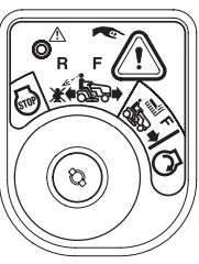
Ignition Module
- WARNING: Never leave a running machine unattended. Always disengage PTO, set parking brake, stop engine and remove key to prevent unintended starting.
- To start the engine, insert the key into the ignition switch and turn clockwise to the START
 position. Release the key into the NORMAL MOWING MODE
  position once the engine has fired.
- To stop the engine, turn the ignition key counterclockwise to the STOP
 position
- CAUTION: Prior to operating the tractor, refer to both Safety Interlock Switches and Starting The Engine in the Operation section of this manual for detailed instructions regarding the Ignition Switch Module and operating the tractor in REVERSE CAUTION MODE
Manual PTO (Blade Engage) Handle

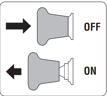
- The PTO/blade engage handle is located on the right fender. Activating the PTO engages power to the cutting deck or other (separately available) attachments. See the Operation section for information and instructions on using the PTO.
- Note: PTO stands for Power Take-Off, which is a mechanism for taking power from a power source, such as a running engine and transmitting it to an application such as the cutting blade of this riding mower.
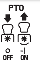
Electric PTO (Blade Engage) Switch
- The PTO switch is located on the dash panel to the right of the LCD Service Minder & Hour Meter.
- Activating the PTO engages power to the cutting deck or other (separately available) attachments.
Transmission Bypass Rod
- The transmission bypass rod is located at the rear of the tractor on the lower right section of the frame.
- When engaged, the rod opens a bypass within the hydrostatic transmissions, which allows the tractor to be pushed short distances by hand. Refer to the Assembly & Set-Up section for instructions on using the bypass feature.
Park Brake/Cruise Control Lever

- Located in the center of the tractor’s dash panel below the steering wheel, the park brake/ cruise control lever is used to engage the parking brake and the cruise control. Refer to the Operation section of this manual for detailed instructions regarding the parking brake.
- NOTE: The parking brake must be set if the operator leaves the seat with the engine running or the engine will automatically shut off.
- NOTE: Cruise control can NOT be engaged at the tractor’s fastest ground speed.
LCD Service Minder & Hour Meter w/ Smart Lawn App Bluetooth® Activation (If Equipped)
- When the ignition key is rotated out of the STOP position but not into the START position, the LCD Service Minder and Hour Meter will briefly display the battery voltage, followed by the tractor’s accumulated hours.
- NOTE: Hours of tractor operation
 are recorded any time the ignition key is rotated out of the STOP position, regardless of whether the engine is started.
Smart Lawn App (If Equipped)

- The app’s automated maintenance dashboard and log will help you keep your machine running at peak performance and protect your investment by tracking total hours across the lifetime of your equipment.
- Receive alert notifications when it’s time to perform essential maintenance tasks. Your dashboard provides real time monitoring and indicates when it’s time for you to check or change the oil, air filter, blades or battery. The app also enables you to locate and contact service centers, access step-by-step instructions to perform routine maintenance and purchase replacement parts directly from your mobile device.
Change Oil
- The LCD will display the letters “CHG”, followed by the letters “OIL”, followed by the letters “SOON”, then finally followed by the meter’s accumulated time. “CHG/OIL/SOON/ TIME” will alternate on the display for 7 minutes after the meter reaches 50 hours. This oil service minder interval will occur every 50 hours. Before the interval expires, change the engine oil as instructed in the Maintenance section of the Engine Operator’s Manual.
Low Oil (If so equipped)
- The letters “LO” followed by the letters “OIL”, then followed by the meter’s accumulated time will indicate the tractor is low on oil. When an engine is not running and immediately after the engine is started the oil pressure may be low. This can trigger the “LO” “OIL” text. This is normal. If the low oil indication persists stop the tractor immediately and check the engine oil level as instructed in the Engine Operator’s Manual.
- NOTE: The “LOW OIL” function only works if the engine is equipped with an oil pressure switch.
Low Battery
- At startup, the battery voltage is briefly displayed then changes to accumulated hours. The letters “LO” will display followed by the letters “BATT” and then followed by the meter’s accumulated time. “LO/BATT/TIME” is displayed on the LCD when the voltage drops below 11.5 volts. When this occurs, the battery is in need of a charge or the engine’s charging system is not generating sufficient amperage. Charge the battery as instructed in the Service section of this manual or have the charging system checked by your local service dealer.
Air Filter Service
- The letters “CLN” will display, followed by the letters “AIR”, followed by “FILT”, then followed by the meter’s accumulated time. “CLN/AIR/FILT/TIME” will alternate on the display for 7 minutes after the meter reaches 50 hours. This air filter service minder time interval will be every 50 hours. On intervals that are common with oil service, the oil message will be displayed first followed by the air filter message.
Operation
Safety Interlock Switches: This tractor is equipped with a safety interlock system for the protection of the operator. If the interlock system should ever malfunction, do not operate tractor. Contact your authorized service dealer.
- The safety interlock system prevents the engine from cranking or starting unless the parking brake is engaged, and the PTO is in the DISENGAGED (OFF) position.
- The engine will automatically shut off if the operator leaves the seat before engaging the parking brake.
- The PTO clutch will automatically shut off if the operator leaves the tractor’s seat with the PTO in the ENGAGED (ON) position, regardless of whether the parking brake is engaged
- With the ignition key in the NORMAL MOWING position, the PTO clutch will automatically shut off if the PTO is moved into the ENGAGED (ON) position with the drive pedal in position for reverse travel.
Starting the Engine
- NOTE: Refer to the Assembly & Set-up section of this manual for Gasoline and Oil fill-up instructions. \Insert the tractor key into the ignition switch module.
- Place the PTO in the disengaged (OFF) position.
- Fully engage the tractor’s brake.
- Move the throttle/choke control into the CHOKE
 position. NOTE: If the engine is warmed up, it may not be necessary to choke the engine.
- Turn the ignition key clockwise to the START position. After the engine starts, release the key. It will return to the NORMAL MOWING position.
- After the engine starts, move the throttle/choke control (if so equipped) down into the FAST
 position or push the choke control (if so equipped) down/in the OFF position. NOTE: Do NOT leave the choke control on while operating the tractor. Doing so will result in a “rich” fuel mixture and cause the engine to run poorly and can damage the engine. NOTE: When operating the tractor be certain that the throttle lever is always in the FAST position. Operating with the throttle at less than full throttle may lead to shortened battery life.
Stopping the Engine WARNING: If you strike a foreign object, stop the engine and disconnect the spark plug wire(s). Thoroughly inspect the machine for any damage. Repair the damage before restarting and operating.
- If the blades are ENGAGED (ON), place the PTO in the DISENGAGED (OFF) position.
- Place the throttle near the SLOW
 position.
- Engage the parking brake.
- Turn the ignition key counterclockwise to the STOP position.
- Remove the key from the ignition switch to prevent unintended starting
Reverse Caution Mode: The REVERSE CAUTION MODE  position of the ignition module allows the tractor to be operated in reverse with the blades (PTO) engaged. NOTE: Mowing in reverse is not recommended. WARNING Use extreme caution while operating the tractor in the REVERSE CAUTION MODE . Always look down and behind before and while backing. Do not operate the tractor when children or others are around. Stop the tractor immediately if someone enters the area. To use the REVERSE CAUTION MODE : NOTE: The operator MUST be seated in the tractor seat.
- Start the engine as previously instructed on the previous page.
- Turn the key from the NORMAL MOWING (Green) position to the REVERSE CAUTION MODE (Yellow) position of the ignition module.
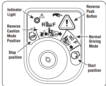
- Press the REVERSE PUSH BUTTON at the top, right corner of the ignition module. The red indicator light at the top, left corner of the ignition module will be ON while activated.
- Once activated (indicator light ON), the tractor can be driven in reverse with the cutting blades (PTO) engaged.
- Always look down and behind before and while backing to make sure no children are around. After resuming forward motion, return key to the NORMAL MOWING position.
- The REVERSE CAUTION MODE will remain activated until:
- The key is placed in either the NORMAL MOWING position or STOP position or
- The operator leaves the seat (electric PTO)/the parking brake is set (manual PTO).
Driving The Tractor: WARNING - Avoid sudden starts, excessive speed and sudden stops.
- Lightly press the brake pedal to release the parking brake. Move the throttle into the FAST position.
- To travel FORWARD, slowly press the forward drive pedal forward until the desired speed is achieved.
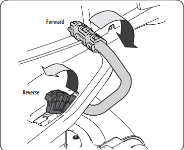
- To travel in REVERSE, check that the area behind is clear then slowly depress the reverse drive pedal until the desired speed is achieved
Driving On Slopes
- Refer to the SLOPE GAUGE on page 8 to help determine slopes where you may operate the tractor safely.
- WARNING: Do not mow on inclines with a slope in excess of 15 degrees (a rise of approximately 2-1⁄2 feet every 10 feet). The tractor could overturn and cause serious injury. Mow up and down slopes, NEVER across. Exercise extreme caution when changing direction on slopes. Watch for holes, ruts, bumps, rocks, or other hidden objects. Uneven terrain could overturn the machine. Tall grass can hide obstacles. Avoid turns when driving on a slope. If a turn must be made, turn down the slope. Turning up a slope greatly increases the chance of a roll over. Avoid stopping when driving up a slope. If it is necessary to stop while driving up a slope, start up smoothly and carefully to reduce the possibility of flipping the tractor over backward.
Engaging the Parking Brake
NOTE: The parking brake must be set if the operator leaves the seat with the engine running or the engine will automatically shut off. To set the parking brake:
- Press the brake pedal completely down with your left foot and hold it in that position.
- Press down on the parking brake/cruise control lever and hold it in that position.
- Remove your foot from the brake pedal.
- Release pressure from the parking brake/cruise control lever.
- After completing step 3, the brake pedal should remain in the down position. If it doesn’t, the parking brake is not engaged. Repeat steps 1-4 to engage.
To disengage the parking brake, lightly press the brake pedal.
WARNING: Never leave a running machine unattended. Always disengage the PTO, set the parking brake, stop the engine and remove the key to prevent unintended starting.
Setting The Cruise Control
WARNING: Never engage the cruise control lever while traveling in reverse.
To set the cruise control:
- Slowly press the forward drive pedal with your right foot until the desired speed is achieved.
- Press down on the parking brake/cruise control lever and hold it in that position.
- Remove your foot from the forward drive pedal.
- Release pressure from the parking brake/cruise control lever.
- After completing step 3, the forward drive pedal should remain in the down position and the tractor will maintain the same forward speed. If it doesn’t, the cruise control is not engaged. Repeat steps 1-4 to engage the cruise control
To disengage the cruise control, lightly press the forward drive pedal or the brake pedal.
NOTE: Cruise control can not be set at the tractor’s fastest ground speed. If the operator should attempt to do so, the tractor will automatically decelerate to the fastest optimal mowing ground speed.
To change the direction of travel from forward to reverse when cruise control is engaged, press the brake pedal to disengage and bring the tractor to a complete stop. Then slowly press the reverse drive pedal with the ball of your foot to travel in reverse.
Using the Deck Lift Lever
- To raise or lower the cutting deck, move the lift lever to the left, then place it in the notch best suited for your application.
Operating the Headlights
- The lamps are ON whenever the ignition key is rotated out of the STOP position. The lamps turn OFF when the ignition key is moved to the STOP position.
Engaging the PTO (Electric PTO tractors)
Engaging the PTO transfers power to the cutting deck or other (separately available) attachments.
To engage the PTO:
- Move the throttle to the FAST position.
- Pull the PTO switch up/out into the engaged (ON) position.
 NOTE: When operating the tractor be certain that the throttle is always in the FAST position. Operating with the throttle at less than full throttle may lead to premature battery wear and a poor quality cut.
- To disengage the PTO, push the PTO switch down/in to the disengaged (OFF) position.
Engaging the PTO (Manual PTO tractors)
Engaging the PTO transfers power to the cutting deck or other (separately available) attachments. To engage the PTO:
- Move the throttle to the FAST position.
- Push the PTO handle forward into the engaged (ON) position

NOTE: When operating the tractor be certain that the throttle is always in the FAST position. Operating with the throttle at less than full throttle may lead to premature battery wear and a poor quality cut.
To disengage the PTO, pull the PTO handle rearward into the disengaged (OFF) position.
Mowing
WARNING: Make certain the area to be mowed is free of debris, sticks, stones, wire or other objects that can be thrown by the rotating blades.
NOTE: Do not engage the mower deck when lowered in grass. Premature wear and possible failure of the belt and PTO clutch will result. Fully raise the deck or move to a non-grassy area before engaging the mower deck.
- Mow up and down slopes, not across.
- Avoid turns when driving on a slope. If a turn must be made, turn down the slope. Turning up a slope greatly increases the chance of a roll over.
- Avoid stopping when driving up a slope. If it is necessary to stop while driving up a slope, start up the slope smoothly and carefully to reduce the possibility of flipping the tractor over backward
- Place the throttle into the FAST position and engage the PTO.
- Lower the mower deck to the desired height setting using the deck lift handle.
- Slowly press the forward drive pedal with your right foot until the desired speed is achieved. NOTE: The speed of the tractor will affect the quality of the mower cut. Mowing at full speed will adversely affect the cut quality. Control the ground speed with forward drive pedal.
- When approaching the other end of the strip, slow down or stop before turning.
- Align the mower with an edge of the mowed strip and overlap approximately 3”.
- Direct the tractor on each subsequent strip to align with a previously cut strip.
- To prevent rutting or grooving of the turf, if possible, change the direction that the strips are mowed by approximately 45° for the next and each subsequent mowing.
WARNING: Be careful when crossing gravel paths or driveways. Disengage the PTO and raise the deck to the highest position before crossing.
NOTE: When stopping the tractor for any reason while on a grass surface, always:
- Make sure the drive pedal is in neutral.
- Engage the parking brake.
- Shut the engine off and remove the key.
- Doing so will minimize the possibility of having your lawn ‘‘browned’’ by hot exhaust from your tractor’s running engine.
Using the Differential Lock (if equipped)
WARNING: When the differential lock is on, be sure to allow for a larger turning radius and greater steering effort.
WARNING: Engage the differential lock only when the vehicle is stationary. Do not use the differential lock when traveling downhill.
NOTE: The system should only be used when poor traction is encountered. It should be disengaged when traveling on surfaces with adequate traction. In some instances, the tractor may be driven in slippery or low-traction situations and it may be necessary to activate the differential lock. To use the differential lock proceed as follows.
- Press down on the brake pedal to stop the motion of the tractor.
- Press down on the differential lock pedal to engage the differential lock. NOTE: The differential lock only works while the pedal is pressed.
- Release the brake pedal to drive the tractor forward while differential lock is engaged. NOTE: Engagement may be delayed. The differential lock will engage when different wheel speeds are detected. NOTE: Disengagement may be delayed. The differential lock will disengage when the rear wheel speeds allow it to release.
- To disengage the differential lock, release the differential lock pedal.
SERVICE AND MAINTENANCE
MAINTENANCE SCHEDULE
WARNING: Before performing any type of maintenance/service, disengage all controls and stop the engine. Wait until all moving parts have come to a complete stop. Disconnect spark plug wire and ground it against the engine to prevent unintended starting. Always wear safety glasses during operation or while performing any adjustments or repairs.
Follow the maintenance schedule given below. This chart describes service guidelines only. Use the Service Log column to keep track of completed maintenance tasks. To locate the nearest authorized Service Center or to schedule service, call the following toll free number.
Refer to the Engine Operator’s Manual for engine maintenance items listed in the table below
1. Each use
- Engine intake screens and cooling fans *
- Exhaust manifold, muffler pipe and muffler shields *
- Check/Clean Hood/Dash Panel Louvers *
- Top and underside of deck, under and around spindle covers and belt area *
- Around fuses, wiring and wiring harnesses *
- Around transmission, axle and fans *
- Engine Oil
- Check (See engine manual)
- Air Filter
- Check (See engine manual)
2. After first 5 hours
- Engine Oil
- Change (break-in period). (See engine manual)
3. Every 10 hours
- Battery terminals
- Hood/Dash panel louvers
- Intake screen
- Blades
- Check/Sharpen/Replace as needed
- Tires
- Front wheels
- Deck
4. Every 25 hours
- Deck wheels
- Deck level/pitch
- Lubrication points
5. Every 50 hours
- Belts and pulleys
- Check for damage and wear
- Engine Oil
- Change (See engine manual)
- Oil Filter
- Replace (See engine manual)
- Air Filter
- Clean or change (See engine manual)
- Fuel Filter
- Replace (See engine manual)
6. Every 100 hours
- Hardware
- Spark plug condition/gap
- Check (See engine manual)
7. Every season/Before storage
- Engine Cooling Fans
- Battery terminals
- Lubrication points
- Hood/Dash panel louvers
- Intake screen
- Blades
- Check/Sharpen/Replace as needed
- Tires
- Deck
- Deck wheels
- Deck level/pitch
- Spark plug condition/gap
- Check (See engine manual)
- Engine Oil
- Change (See engine manual)
- Oil Filter
- Replace (See engine manual)
8. Miscellaneous
- Valve lashing (camshaft/valve clearance) ^
*-- Perform more often in dry conditions and/or when mulching
^ -- Have this item performed by a qualified service dealer
NOTE: This Operator’s Manual covers several models. Tractor features may vary by model. Not all features in this manual are applicable to all tractor models and the tractor depicted may differ from yours.
WARNING: Before performing any maintenance or repairs, disengage the PTO, set the parking brake, stop the engine and remove the key to prevent unintended starting.
Post-Operation Tractor Care
- After each operation of the tractor, the following procedures should be implemented to extend the life of your tractor and ensure safe operating conditions.
- DANGER: Failure to follow these recommendations may result in serious injury to yourself or others and may cause damage to the tractor.
Cleaning the Underside of the Deck
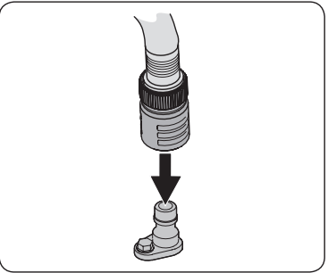
Deck Wash System: Your tractor’s deck is equipped with a water port on its surface as part of its deck wash system. Use the Smart Jet to rinse grass clippings from the deck’s underside and prevent the buildup of corrosive chemicals. Complete the following steps AFTER EACH MOWING:
- Drive the tractor to a level, clear spot on your lawn, near enough for your garden hose to reach.
- Disengage the PTO, set the parking brake and stop the engine.
- Thread the hose coupler (packaged with your tractor’s Operator’s Manual) onto the end of your garden hose.
- Attach the hose coupler to the water port on your decks surface.
- Turn the water on.
- While sitting in the operator’s position on the tractor, start the engine and place the throttle lever in the FAST position.
- Move the tractor’s PTO into the engaged (ON) position.
- Remain in the operator’s position with the deck engaged for a minimum of two minutes, allowing the underside of the deck to thoroughly rinse.
- Move the tractor’s PTO into the disengaged (OFF) position.
- Turn the ignition key to the STOP position to turn the tractor’s engine off.
- Turn the water off and detach the hose coupler from the water port on your deck’s surface.
- After cleaning your deck with the Smart Jet system, return to the operator’s position and engage the PTO. Keep the deck running for a minimum of two minutes, allowing the underside of the deck to thoroughly dry
Cleaning the Tractor - WARNING: If the tractor has been recently run, the engine, muffler and surrounding metal surfaces will be hot and can cause burns to the skin. Let the engine cool for at least five minutes Exercise caution to avoid burns. Your tractor should be cleaned after each use and under certain conditions, i.e. dry conditions and/or mulching situations, additional cleaning may be necessary. One of the best ways to keep your tractor running efficiently and to reduce fire risk is to regularly remove debris buildup from the tractor. Follow the recommendations below and contact your authorized dealer with any questions.
- Allow the machine to cool in an open area before cleaning.
- Do not use water on any part of the tractor except the underside of the cutting deck. Doing so can cause damage to the tractor’s spindle bearings, electrical system and engine, leading to premature failures. The use of compressed air and/or leaf blower will help keep the tractor clean.
- Clean under the hood. Exhaust manifold, around fuses, all wiring and harnesses, muffler pipe, muffler shield, engine intake screens and cooling fins, etc.
- Clean the top of the mower deck, under the spindle covers and belt area.
- Clean around and near the transmission, axle and the fan area
- Debris can accumulate anywhere on the tractor, especially on horizontal surfaces. Additional cleaning may be necessary when mowing in dry conditions or when mulching.
- Fuel leaks/spills, oil leaks/spills and excess lubrication can also become collection sites for debris. Immediate repair and cleaning up oil or fuel spills can help reduce fire hazards.
- In addition to cleaning the tractor before operating and storing, do not attempt to mow unusually tall grass (10” or higher), dry grass (e.g., pasture) or piles of dry leaves. Dry grass or leaves may contact the engine exhaust and/or build up on the mower deck presenting a potential fire hazard.
Storing the Tractor
- Allow the machine to cool in an open area before storing.
- Do not park the tractor near any flammable materials (wood, cloth or chemicals) or any open flames or other potential source of ignition (furnace, water heater or any other type of heater).
- Remove all combustible materials from the tractor before storing. Empty cargo boxes, grass catchers or containers.
- Always shut off fuel flow when storing or transporting if tractor is equipped with a fuel shutoff.
- Check the fuel system (lines, tank, cap and fittings) frequently for cracks or leaks. Repair and clean as necessary.
Engine
Refer to the Engine Operator’s Manual for all engine maintenance procedures and instructions for checking and adding oil. See the Changing the Engine Oil section below for oil changing procedures and instructions.
- NOTE: If the “LOW OIL” text appears immediately after the engine is started the oil pressure may be low. This is normal. If the low oil indication persists stop the tractor immediately and check the engine oil level as instructed in the Engine Operator’s Manual.
- NOTE: The “LOW OIL” function only works if the engine is equipped with an oil pressure switch.
Changing the Engine Oil: To complete an oil change, proceed as follows:
- Run the engine for a short time to warm the engine oil. The oil will flow more freely and carry away more impurities. Use care to avoid burns from hot oil.
- Locate the oil drain hose on the left side of the engine.
- Place an appropriate oil collection container with at least a 2.5 quart capacity below the opening of the oil drain tube, to collect the used oil. Remove the oil fill cap/dipstick from the oil fill tube.
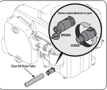
- Pop open the protective cap on the end of the oil drain valve to expose the drain port.
- Remove the oil fill cap/dipstick from the oil fill tube.
- Push the clear oil drain tube (packed with this manual) onto the oil drain port. Route the opposite end of the tube into an appropriate oil collection container with at least a 2.5 quart capacity to collect the used oil.
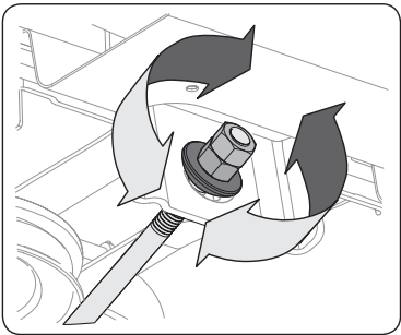
- The engine is equipped with a twist-and-pull drain port. Turn the oil drain valve 1⁄4-turn counter-clockwise, then pull outward to begin draining oil. After the oil has finished draining, push the end of the oil drain valve back in and turn 1⁄4-turn clockwise to secure it back in place. Re-cap the end of the oil drain valve to keep debris from entering the drain port.
- Replace the oil filter, and refill the engine with new oil as instructed in the engine operator’s manual. NOTE: Place an absorbent towel beneath the oil filter to keep oil off the clutch.
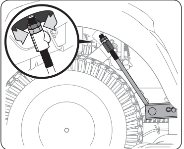
- To refill the oil, re-install the plug at the end of the tube and refer to the engine operator’s manual for refilling instructions, oil type and amount. NOTE : Maintenance, repair, or replacement of the emission control devices and systems which are being done at owner’s expense may be performed by any engine repair establishment or individual. Warranty repairs must be performed by an authorized dealer
Hydrostatic Transmission: The hydrostatic transmission is sealed at the factory and is maintenance-free. The fluid level cannot be checked and the fluid cannot be changed.
Hydrostatic Neutral Adjustment: If the tractor creeps forward or rearward when neither the forward nor reverse pedal is depressed, contact your authorized dealer to have the neutral setting properly adjusted.
Cleaning the Tractor: Any fuel or oil spilled on the machine should be wiped off promptly. Do NOT allow debris to accumulate around the cooling fins of the engine, the transmission’s cooling fan or on any other part of the machine.
Lubrication
Front Wheels
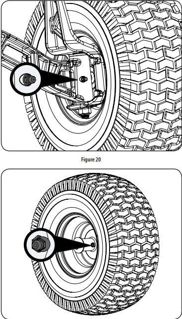
- Each of the front wheel axles and rims is equipped with a grease fitting. See Figure 20 for the location of the grease fitting on the axles and Figure 21 for the location of the grease fitting on the rims. Lubricate with a No. 2 multi-purpose grease applied with a grease gun after every 25 hours of tractor operation.
- Deck Wheels: The wheels on the deck are equipped with a grease fitting. Lubricate with a No. 2 multi-purpose grease applied with a grease gun after every 25 hours of tractor operation.
- Pivot Points & Linkage: Lubricate all the pivot points on the drive system, parking brake and lift linkage at least once a season with light oil.
- Note: It is not necessary to grease the steering pinion/sector gear interface. Doing so will allow dirt to accumulate and can affect steering performance
Adjustments
WARNING: Shut the engine off, remove the ignition key and engage the parking brake before making adjustments. Protect your hands by using heavy gloves when handling the blades.
NOTE : Check the tractor’s tire pressure before performing any deck leveling adjustments. Refer to Tires on page 11 for information regarding tire pressure.
Adjusting the Deck - Leveling the Deck (Front-To-Rear): The front of the cutting deck is supported by a stabilizer bar that can be adjusted to level the deck from front to rear. The front of the deck should be between 1⁄4-3⁄8” lower than the rear of the deck. Adjust if necessary as follows:
- Park the tractor on a firm, level surface and place the deck lift lever in the middle position and rotate the blade nearest the discharge chute so that it is parallel with the tractor.
- Measure the distance from the front of the blade tip to the ground and the rear of the blade tip to the ground. The front of the deck should be between 1⁄4-3⁄8” less than the rear of deck.
- Determine the approximate distance necessary for proper adjustment and proceed, if necessary.
- To raise the front of the deck, loosen the outer nut then tighten (thread inward) the nut against the front hanger bracket. When proper adjustment is achieved, re-tighten the outer nut to 25-30 ft.-lbs
- To lower the front of the deck, loosen the outer nut then loosen (thread outward) the nut, away from the front hanger bracket. When proper adjustment is achieved, re-tighten the outer nut.
Leveling the Deck (Side-to-Side): If the cutting deck appears to be mowing unevenly, a side to side adjustment can be performed. Adjust if necessary as follows:
- With the tractor parked on a firm, level surface, place the deck lift lever in the middle position and rotate both blades so that they are perpendicular with the tractor.
- Measure the distance from the outside of the left blade tip to the ground and the distance from the outside of the right blade tip to the ground. Both measurements taken should be equal. If they’re not, proceed to the next step.
- Under the rear fenders inside the wheels there is a lift adjustment rod for each side of the deck
- Minor side-to-side adjustments should be made using primarily the left adjustment rod.
- To raise the left side of the deck, loosen the upper nut on the end of the lift rod, then turn the lower nut clockwise. When the proper adjustment is achieved, tighten the upper nut to secure in place. To lower the left side of the deck, loosen the upper nut on the end of the lift rod, then turn the lower nut counterclockwise. When the proper adjustment is achieved, tighten the upper nut to 25-30 ft-lbs. to secure in place.
- The deck is properly leveled when both blade tip measurements taken earlier are equal.
Adjusting the Deck Height: The height of the deck can be adjusted to ensure that the setting on your deck height lever is accurate. To adjust the deck height proceed as follows:
- Park the tractor on a firm, level surface and place the deck lift lever in the highest position (4”) and rotate the blade nearest the discharge chute so that it is perpendicular with the tractor.
- Measure the distance from the outside of the left blade tip to the ground and the distance from the outside of the right blade tip to the ground. Both measurements taken should be 4”. If they’re not, proceed to the next step.
- Using the right and left lift rods, raise or lower the necessary side of the deck until both sides are measured at 4” from the pavement.
Adjusting the Deck Wheels
- WARNING: Keep hands and feet away from the discharge opening of the cutting deck.
- NOTE: The deck wheels are an anti-scalp feature of the deck and are not designed to support the weight of the cutting deck.
- The deck wheels should be approximately 1⁄4-1⁄2” above the ground when the deck is set in the desired height setting. To adjust the deck wheels see the Assembly & Set-Up section for instructions.
Seat Adjustment
- Refer to the Assembly & Set-Up section of this manual for seat adjustment instructions.
- WARNING: Before operating the tractor, make sure the seat is engaged in the seatstop. Engage the parking brake. Stand behind the machine and pull back on seat until it clicks into place.
Parking Brake Adjustment
- If the tractor does not come to a complete stop when the brake pedal is completely depressed, or if the tractor’s rear wheels can roll with the parking brake applied (and the hydrostatic relief valve open), the brake is in need of adjustment. See your authorized service dealer to have the brake adjusted.
Wheel Alignment
- If your tractor pulls to one side or is out of alignment, a wheel alignment might be necessary. Take your tractor to an authorized service dealer to have the wheels properly aligned.
Service
Battery: The battery is sealed and is maintenance-free. Acid levels cannot be checked and fluid can not be added.
- Always keep the battery cables and terminals clean and free of corrosive build-up.
- After cleaning the battery and terminals, apply a light coat of petroleum jelly or grease to both terminals.
Jump Starting
- Connect positive (+) cable to positive (+)post of your tractor’s discharged battery.
- Connect the other end of the cable to the positive (+) post of the jumper battery.
- Connect the second cable negative (–) to the other post of the jumper battery.
- Make the final connection on the engine block of the tractor, away from the battery. Attach to an unpainted part to assure a good connection.
- Start the tractor (as instructed in the Operation section of this manual).
- Remove the jumper cables in reverse order of connection.
Charging: If your tractor has not been put into use for an extended period of time, charge the battery as follows:
- Set your battery charger to deliver a max of 10 amperes.
- If your battery charger is automatic, charge the battery until the charger indicates that charging is complete. If the charger is not automatic, charge for no fewer than eight hours
Fuse
- WARNING: Before servicing, repairing, or inspecting, always disengage PTO, set parking brake, stop engine and remove key to prevent unintended starting.
- A 20 AMP fuse is installed in your tractor’s wiring harness to protect the tractor’s electrical system from damage caused by excessive amperage.
- If the electrical system does not function, or your tractor’s engine will not crank, check to be certain that the fuse has not blown. It is located under the seat, attached to the POSITIVE (Red) wire leading to the battery.
- CAUTION: Always use a replacement fuse with the same amperage capacity as the blown fuse.
Relays and Switches
- There are several safety switches in the electrical system. If a function of the safety interlock system described earlier is not functioning properly, have the electrical system checked by your authorized service dealer.
Cutting Deck Removal 42”Decks
1. To remove the cutting deck, proceed as follows:
- Place the PTO in the disengaged (OFF) position and engage the parking brake.
- Lower the deck by moving the deck lift lever into the bottom notch on the right fender.
- Remove the hex screw securing the engine pulley keeper rod to the frame.
- Slide the rod to the right to remove it
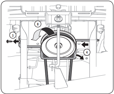
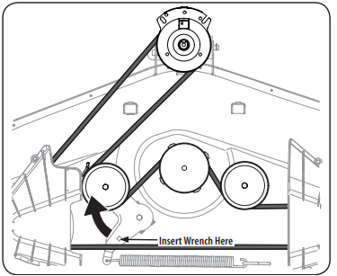
- Remove the bow-tie pin that secures the PTO cable to the bracket on the deck, pull back on the PTO cable, then slide it out of the bracket and unhook the spring from the idler bracket.
- Working on the right side of the tractor, insert a 3⁄8” drive ratchet wrench, set to tighten, into square hole found on the idler bracket.
- Skip ahead to Step 2
Cutting Deck Removal 46” Decks
1. To remove the cutting deck, proceed as follows:
- Place the PTO in the disengaged (OFF) position and engage the parking brake.
- Lower the deck by moving the deck lift lever into the bottom notch on the right fender.
- Working on the right side of the tractor, insert a 3⁄8” drive ratchet wrench, set to tighten, into square hole found on the idler bracket
- Skip ahead to Step 2
Cutting Deck Removal 50” & 54” Decks
1. To remove the cutting deck, proceed as follows:
- Place the PTO in the disengaged (OFF) position and engage the parking brake.
- Lower the deck by moving the deck lift lever into the bottom notch on the right fender.
- Working on the right side of the tractor, insert a 3⁄8” drive ratchet wrench, set to tighten, into square hole found on the idler bracket
- Continue with Step 2
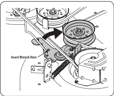
2. Use the wrench to pivot the deck drive pulley forward.
3. Carefully remove the belt from around the PTO pulley.
4. Looking at the cutting deck from the right side of the tractor, locate the bow-tie pin on the rear right side of the deck
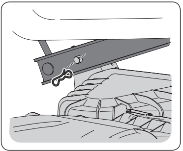
5. Remove the bow pin and slide the deck pin out of the deck lift arm.
6. Repeat the above steps on the tractor’s left side.
7. Pull the bow-tie pin out of the front deck lift rod securing it to the deck. Slide the deck lift rod out of the front hanger bracket.
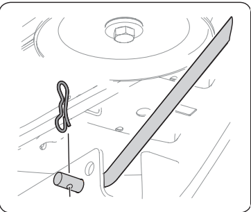
8. Move the deck lift lever into the top notch to raise the deck lift up and out of the way.
9. Gently slide the cutting deck out from underneath the tractor.
Cutting Blades: To remove the blades, proceed as follows.
1. Remove the deck from beneath the tractor, (refer to Cutting Deck Removal earlier in this section) then gently flip the deck over to expose its underside.
2. Place a block of wood between the deck housing baffle and the cutting blade to act as a stabilizer
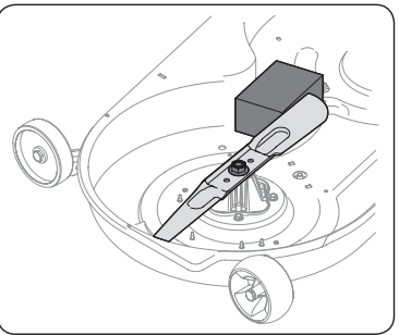
3. Remove the hex flange nut that secures the blade to the spindle assembly.
4. To properly sharpen the cutting blades, remove equal amounts of metal from both ends of the blades along the cutting edges, parallel to the trailing edge, at a 25°- to 30° angle. Always grind each cutting blade edge equally to maintain proper blade balance.
5. Test the blade’s balance using a blade balancer. Grind metal from the heavy side until it balances evenly. NOTE: When replacing the blade, be sure to install the blade with the side of the blade marked ‘‘Bottom’’ (or with a part number stamped in it) facing the ground when the mower is in the operating position.
Changing the Deck Belt: All belts on your tractor are subject to wear and should be replaced if any signs of wear are present . To change or replace the deck belt on your tractor, proceed as follows:
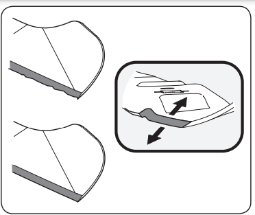
1. Remove the deck as instructed earlier in this section under Cutting Deck Removal. NOTE: On some decks it may be necessary to remove the spindle covers to remove and/or install the new belt. To remove the spindle covers, remove the screws securing them to the deck.
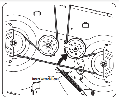
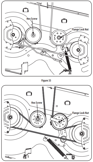
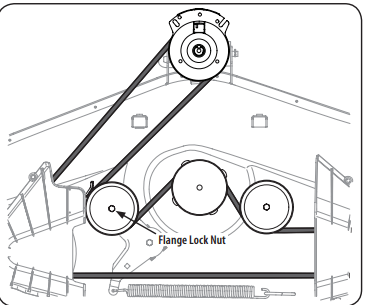
2. Loosen, but do not remove the flange lock nut on the left idler pulley for 50” and 54” Decks and the right idler pulley for 42” and 46” Decks. See Figure 33 for 42” Decks, Figure 34 for 46” Decks and Figure 35 for 50” and 54” Decks.
3. Carefully remove the belt from around the idler pulleys and the spindle pulleys
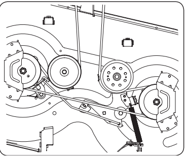
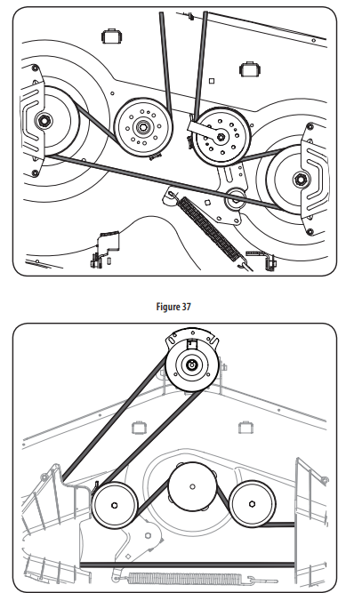
4. Route the new belt as shown in Figure 36 for 42” Decks, Figure 37 for 46” Decks and Figure 38 for 50” and 54” Decks.
5. Retighten idler pulleys.
6. Remount the spindle covers if removed after step 1.
7. Re-install the deck making sure the belt remains routed around the pulleys as instructed.
8. Pull the right side of the belt and place the narrow V side of the belt into the PTO pulley

9. While holding the belt and pulley together, rotate the pulley to the left. Continue holding and rotating the pulley and belt until the belt is fully rolled into the PTO pulley
Changing the Transmission Drive Belt: Several components must be removed and special tools used in order to change the tractor’s transmission drive belt. See a qualified service dealer to have the transmission drive belt replaced.
OFF-SEASON STORAGE
WARNING: Never store lawn tractor with fuel in tank indoors or in poorly ventilated areas where fuel fumes may reach an open flame, spark, or pilot light as on a furnace, water heater, clothes dryer, or gas appliance
PREPARING THE ENGINE
IMPORTANT: Fuel left in the fuel tank during warm weather deteriorates and will cause serious starting problems.
CAUTION: Failure to use a fuel stabilizing additive or completely run the engine until it’s out of fuel before off-season storage may result in damage to your engine’s carburetor. Subsequent damage would not be covered under the manufacturer’s warranty.
Engines stored between 30 and 90 days need to be treated with a gasoline stabilizer and engines stored over 90 days need to be drained of fuel to prevent deterioration and gum from forming in fuel system or on essential carburetor parts. If the gasoline in your engine deteriorates during storage, you may need to have the carburetor, and other fuel system components, serviced or replaced.
To prevent gum deposits from forming inside the engine’s carburetor and causing possible malfunction of the engine, the fuel system must be either completely emptied, or the gasoline must be treated with a stabilizer to prevent deterioration.
- If using a fuel stabilizer:
- Read the product manufacturer’s instructions and recommendations.
- Add to clean, fresh gasoline the correct amount of stabilizer for the capacity of the fuel system.
- Fill the fuel tank with treated fuel and run the engine for 2-3 minutes to get stabilized fuel into the carburetor.
- If emptying the fuel system:
- Do not drain fuel when the engine is hot. Allow the engine adequate time to cool. Drain fuel into an approved container outdoors, away from open flame.
- Drain any large volume of fuel from the tank by disconnecting the fuel line from the in-line fuel filter near the engine. See the complete instructions for Draining The Fuel later in this section. WARNING Gasoline is extremely flammable and can be explosive under certain conditions. Drain gasoline before storing the equipment for extended periods. Drain fuel only into an approved container outdoors, away from an open flame. Allow engine to cool. Extinguish cigarettes, cigars, pipes, and other sources of ignition prior to draining fuel. Store gasoline in an approved container in safe location.
- Reconnect the fuel line and run the engine until it starts to falter, then use the choke to keep the engine running until all fuel in the carburetor has been exhausted.
- Disconnect the fuel line and drain any remaining gasoline from the system.
- Remove the spark plug and pour one (1) ounce of engine oil through the spark plug hole into the cylinder. Crank the engine several times to distribute the oil. Replace the spark plug.
- Clean debris from around engine, under finger guard, and under, around and behind muffler. Touch up any damaged paint, and coat other areas that may rust with a light film of oil.
- Store in a clean, dry and well ventilated area away from any appliance that operates with a flame or pilot light, such as a furnace, water heater, or clothes dryer. Also avoid any area with a spark producing electric motor, or where power tools are operated.
- If possible, also avoid storage areas with high humidity, because that promotes rust and corrosion.
- Keep the engine level in storage. Tilting can cause fuel or oil leakage
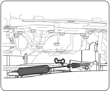
DRAINING THE FUEL
- Locate the fuel filter, which is located on the left side of the engine, and may be attached to the engine with a tie strap.
- Cut the tie strap, if present, then pinch the in-line clamp on the fuel filter with a pair of pliers, slide the clamp up the fuel line.
- Pull the fuel line free from the filter and place the open end of the line into an approved container to drain the fuel.
PREPARING THE LAWN TRACTOR
- Clean and lubricate the unit thoroughly as described in the Lubrication instructions in the Service and Maintenance section
- Do not use a pressure washer or garden hose to clean your unit.
- Store mower in a dry, clean area. Do not store next to corrosive materials, such as fertilizer.
Removing From Storage
- Check the oil level as described in the Assembly section of this manual.
- If the fuel was drained during storage preparation, fill the tank with fresh gasoline. If you keep a container of gasoline for refueling, make certain it contains only fresh fuel. Gasoline oxidizes and deteriorates over time, causing hard starting.
- If the cylinder was coated with oil during storage preparation, the engine will smoke briefly at startup. This is normal.
TROUBLESHOOTING
WARNING: Before performing any type of maintenance/service, disengage all controls and stop the engine. Wait until all moving parts have come to a complete stop. Disconnect spark plug wire and ground it against the engine to prevent unintended starting. Always wear safety glasses during operation or while performing any adjustments or repairs
1. Engine fails to start
- PTO/Blade Engage knob engaged.
- Place knob in disengaged (OFF) position.
- Parking brake not engaged.
- Spark plug wire disconnected.
- Connect wire to spark plug.
- Throttle control lever not in correct starting position.
- Place Throttle lever to FAST position.
- Fuel tank empty, or stale fuel.
- Fill tank with clean, fresh (less than 30 days old) gas
- Blocked fuel line.
- Replace fuel line. See a qualified service dealer. Replace fuel filter. See the Service and Maintenance section.
- Faulty spark plug.
- Clean, adjust gap or replace plug.
- Engine flooded.
- Crank engine with throttle in FAST position.
- Fuse(s) blown
2. Engine runs erratically
- Tractor running with Choke activated.
- Check that the electric choke is working. See a qualified service dealer
- Spark plug wires loose.
- Connect and tighten spark plug wires
- Blocked fuel line or stale fuel.
- Replace fuel line. See a qualified service dealer. Fill tank with clean, fresh gasoline and replace fuel filter. See the Service and Maintenance section.
- Vent in gas cap plugged.
- Clear vent or replace cap if damaged
- Water or dirt in fuel system.
- Drain fuel tank. Refill with clean, fresh gasoline. See the Service and Maintenance section
- Dirty air cleaner
- Clean or replace air cleaner paper element or clean foam pre-cleaner.
3. Engine overheats
- Engine oil level low
- Fill engine with proper amount and type of oil.
- Air flow restricted
- Clean grass clippings and debris from around the engine’s cooling fins and blower housing.
4. Engine hesitates at high RPMs
- Spark plug gap set too close
- Remove spark plug and adjust gap.
5. Engine idles poorly
- Fouled spark plug
- Replace spark plug and adjust gap.
- Dirty air cleaner
- Clean or replace air cleaner element and/or clean pre-cleaner
6. Excessive vibration
- Cutting blades loose or unbalanced
- Tighten blade and spindle. Balance blade.
- Damaged, dull, or bent cutting blade
7. Mower will not mulch grass
- Engine speed too low.
- Place Throttle control in FAST (rabbit) position.
- Wet grass.
- Do not mulch when grass is wet
- Excessively high grass.
- Mow once at a high cutting height, then mow again at desired height or make a narrower cutting swath
- Dull blade.
- Sharpen or replace blade.
8. Uneven cut
- Deck not leveled properly.
- Perform side-to-side deck adjustment
- Dull blade.
- Uneven tire pressure.
- Check tire pressure in all four tires