per'ator's nual
I:RRFrSMRN°
ZERO=TURN RIDER
27 HP, 48" MOWER DECK
Model No. 247,25003
CAUTION: Before using this product,
read this manual and follow all safety
rules and operating instructions,
, SAFETY
ASSEMBLY
OPERATION
MAINTENANCE
PARTS LIST
o ESPANOL
Sears Brands Management Corporation, Hoffman Estates, IL 60179, U.S.A.
Visit our website: www.craftsman.com
FormNo.769-07656
(February22,2012)
Warranty Statement .................................. Page 2
Safe Operation Practices .......................... Pages 3-8
Assembly .................................................. Pages 9-11
Operation .................................................. Pages 12-21
Service and Maintenance ......................... Pages 22-33
Off-Season Storage .................................. Page 34
Troubleshooting ........................................ Page 35-36
Parts List ..................................................... Pages 38-61
Engine Parts List ....................................... Pages 62-75
Labels ....................................................... Page 76
Repair Protection Agreement ................... Page 79
Espafiol ..................................................... Page 84
Service Numbers ...................................... Back Cover
CRAFTSMAN FULL WARRANTY
FORTHREEYEARSfromthe dateof purchase,all non-expendabbpartsof this ridingequipmentarewarrantedagainstanydefectsinmaterial
orworkmanship.Adefectivenon-expendablepartwill receivefreein-homerepairor replacementif repairis impossible.
FOR90 DAYSfromthe dateof purchase,the battery(anexpendablepart)of this ridingequipmentis warrantedagainstany defectsinmaterialor
workmanship(ourtestingprovesthat it will notholda charge).A defectivebatterywill receivefree in-homereplacement.
WARRANTYSERVICE
Forwarrantycoveragedetailsto obtainfree repairor replacement,call 1-800-659-5917or visitthe website: www.craftsman.com
In allcasesabove,if part repairor replacementis impossible,the ridingequipmentwill be replacedfreeof chargewiththe sameor anequivalent
model.
Allof the abovewarrantycoverageis void if thisridingequipmentis everusedwhileprovidingcommercialservicesor if rentedto anotherperson.
ThiswarrantycoversONLYdefectsin materialandworkmanship.Warrantycoveragedoes NOTinclude:
• Expendableparts(exceptbattery)thatcanwear outfromnormalusewithinthe warrantyperiod,includingbut not limitedto blades,spark
plugs,air cleaners,belts,andoilfilters.
• Standardmaintenanceservicing,oilchanges,or tune-ups.
• Tire replacementor repaircausedby puncturesfromoutsideobjects,suchas nails,thorns,stumps,or glass.
Tireor wheelreplacementor repairresultingfromnormalwear,accident,or improperoperationor maintenance.
Repairsnecessarybecauseof operatorabuse,includingbutnot limitedto damagecausedby towingobjectsbeyondthe capabilityof the
ridingequipment,impactingobjectsthatbendthe frame,axle assemblyor crankshaft,orover-speedingthe engine.
• Repairsnecessarybecauseof operatornegligence,includingbutnot limitedto,electricalandmechanicaldamagecausedby improper
storage,failureto usethe propergradeand amountof engineoil,failureto keepthe deckclearof flammabledebris,orfailureto maintainthe
ridingequipmentaccordingto the instructionscontainedin theoperator'smanual.
• Engine(fuel system)cleaningor repairscausedbyfuel determinedto becontaminatedor oxidized(stale). Ingeneral,fuel shouldbeused
within30 daysof itspurchasedate.
Normaldeteriorationandwearof the exteriorfinishes,or productlabelreplacement.
o
Thiswarrantygivesyou specificlegalrights,and youmayalsohaveotherrightswhichvaryfromstateto state.
Sears Brands ManagementCorporation, Hoffman Estates, IL 60179
EngineOil: 15W-40
Fuel: UnleadedGasoline
SparkPlug: RC12YC
Engine: KohlerSV840-3021
ModelNumber
Serial Number
Dateof Purchase
Recordthe modelnumber,serialnumber,
anddateof purchaseabove.
© KCD IR LLC 2
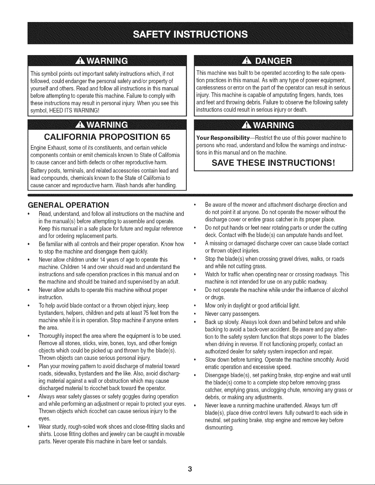
Thissymbolpointsout importantsafetyinstructionswhich,if not
followed,couldendangerthepersonalsafetyand/orpropertyof
yourselfandothers. Readandfollowall instructionsin thismanual
beforeattemptingto operatethismachine.Failureto complywith
theseinstructionsmayresultin personalinjury.Whenyou seethis
symbol,HEEDITSWARNING!
CALIFORNIA PROPOSITION 65
EngineExhaust,someof itsconstituents,andcertainvehicle
componentscontainoremitchemicalsknownto Stateof California
to causecancerandbirthdefectsorother reproductiveharm.
Batteryposts,terminals,and relatedaccessoriescontainleadand
leadcompounds,chemicalsknownto the Stateof Californiato
causecancerandreproductiveharm.Washhandsafterhandling.
Thismachinewasbuiltto beoperatedaccordingto the safeopera-
tion practicesinthis manual.As withanytypeof powerequipment,
carelessnessorerroron the partof the operatorcan resultin serious
injury.Thismachineis capableof amputatingfingers,hands,toes
andfeetandthrowingdebris.Failureto observethe followingsafety
instructionscouldresultin seriousinjuryor death.
Your Responsibility--Restrictthe use of thispowermachineto
personswho read,understandandfollowthewarningsand instruc-
tionsin thismanualandon the machine.
SAVE THESE INSTRUCTIONS!
GENERAL OPERATION
• Read,understand,andfollowall instructionson the machineand
in themanual(s)beforeattemptingto assembleandoperate.
Keepthis manualina safeplacefor futureand regularreference
andfor orderingreplacementparts.
• Befamiliarwithall controlsandtheir properoperation.Knowhow
to stopthe machineanddisengagethemquickly.
• Neverallowchildrenunder14yearsof ageto operatethis
machine.Children14andover shouldreadandunderstandthe
instructionsandsafeoperationpracticesin thismanualandon
the machineandshouldbetrainedandsupervisedbyan adult.
• Neverallowadultsto operatethis machinewithoutproper
instruction.
• Tohelpavoidbladecontactor a thrownobjectinjury,keep
bystanders,helpers,childrenandpetsat least75feetfromthe
machinewhile it is in operation.Stopmachineif anyoneenters
the area.
• Thoroughlyinspectthe areawherethe equipmentis to be used.
Removeallstones,sticks,wire,bones,toys,andotherforeign
objectswhichcouldbe pickedupandthrownby the blade(s).
Thrownobjectscan causeseriouspersonalinjury.
• Planyour mowingpatternto avoiddischargeof materialtoward
roads,sidewalks,bystandersandthe like.Also,avoiddischarg-
ingmaterialagainstawall orobstructionwhichmaycause
dischargedmaterialto ricochetbacktowardthe operator.
• Alwayswearsafetyglassesorsafetygogglesduringoperation
andwhileperforminganadjustmentor repairto protectyour eyes.
Thrownobjectswhichricochetcan causeseriousinjuryto the
eyes.
• Wearsturdy,rough-soledworkshoesandclose-fittingslacksand
shirts.Loosefittingclothesandjewelrycan becaughtin movable
parts.Neveroperatethis machinein barefeetor sandals.
• Be awareof the mowerand attachmentdischargedirectionand
do not pointit at anyone.Donot operatethe mowerwithoutthe
dischargecoverorentiregrasscatcherin its properplace.
• Donot put handsor feet near rotatingpartsor underthe cutting
deck. Contactwiththe blade(s)can amputatehandsandfeet.
• A missingor damageddischargecovercan causebladecontact
or thrownobjectinjuries.
• Stoptheblade(s)whencrossinggraveldrives,walks,or roads
andwhile notcuttinggrass.
• Watchfor trafficwhenoperatingnearorcrossingroadways.This
machineis not intendedfor useonany public roadway.
• Donot operatethe machinewhile underthe influenceof alcohol
or drugs.
• Mowonly in daylightor good artificiallight.
• Nevercarrypassengers.
• Backup slowly.Alwayslookdown andbehindbeforeandwhile
backingto avoida back-overaccident.Beawareand payatten-
tion to the safetysystemfunctionthatstopspowerto the blades
whendrivingin reverse.If notfunctioningproperly,contactan
authorizeddealerfor safetysysteminspectionand repair.
• Slowdown beforeturning.Operatethe machinesmoothly.Avoid
erraticoperationandexcessivespeed.
• Disengageblade(s), set parkingbrake,stop engineand wait until
the blade(s)cometo acompletestopbeforeremovinggrass
catcher,emptyinggrass,uncloggingchute,removingany grass or
debris,or makinganyadjustments.
• Neverleavea runningmachineunattended.Alwaysturn off
blade(s),placedrivecontrollevers fullyoutwardto each sidein
neutral,set parkingbrake,stopengineandremovekeybefore
dismounting.
3
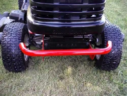
• Useextracare whenloadingorunloadingthe machineintoa
trailerortruck.Thismachineshouldnot bedrivenupor down
ramp(s),becausethe machinecouldtip over,causingserious
personalinjury.The machinemustbe pushedmanuallyon
ramp(s)to loador unloadproperly.
• Mufflerand engine becomehotand can causea burn.Do not
touch.
• Checkoverheadclearancescarefullybeforedrivingunderlow
hangingtree branches,wires,dooropeningsetc.,wherethe
operatormaybestruckor pulledfromthe machine,whichcould
resultinseriousinjury.
• Disengageallattachmentclutches,set the parkingbraketo the
'on' positionandmovethe RHand LHdrivecontrolleversfully
outwardto eachsideto the neutralpositionbeforeattemptingto
startthe engine.
• Yourmachineisdesignedto cut normalresidentialgrass of a
heightnomorethan 10".Do not attemptto mowthroughunusually
tall,dry grass(e.g.,pasture)orpiles of dry leaves.Drygrassor
leavesmaycontactthe engineexhaustand/or build up on the
mowerdeckpresentinga potentialfire hazard.
• Useonlyaccessoriesandattachmentsapprovedfor this machine
by the machinemanufacturer.Read,understandandfollowall
instructionsprovidedwiththe approvedaccessoryor attachment.
• Dataindicatesthatoperators,age 60 years and above,are
involvedin a largepercentageof ridingmower-relatedinjuries.
Theseoperatorsshouldevaluatetheirabilityto operatethe riding
mowersafelyenoughto protectthemselvesandothersfrom
seriousinjury.
• If situationsoccurwhicharenot coveredinthismanual,usecare
andgoodjudgment.Contactthe CraftsmanHelpLineat 1-800-
659-5917for assistance.
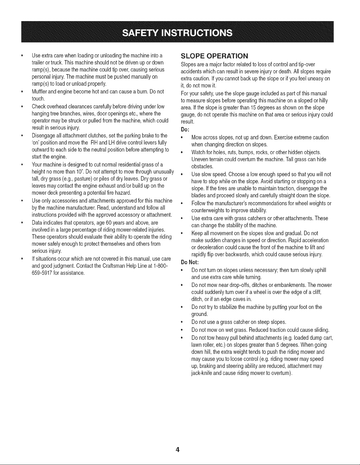
SLOPE OPERATION
Slopesarea majorfactorrelatedto lossof controlandtip-over
accidentswhichcan resultinsevereinjuryor death.Allslopesrequire
extracaution.Ifyoucannotbackupthe slopeor if youfeel uneasyon
it, do not mowit.
Foryoursafety,use the slopegaugeincludedas part of thismanual
to measureslopesbeforeoperatingthis machineona slopedor hilly
area. Ifthe slopeis greaterthan15degreesas shownonthe slope
gauge,donot operatethis machineonthatareaor seriousinjurycould
result.
Do:
o
Mowacrossslopes,not upanddown.Exerciseextremecaution
whenchangingdirectionon slopes.
Watchfor holes,ruts,bumps,rocks,orother hiddenobjects.
Uneventerraincouldoverturnthe machine.Tallgrasscan hide
obstacles.
Useslowspeed.Choosea lowenoughspeedso thatyouwill not
haveto stopwhileon the slope.Avoidstartingor stoppingon a
slope.Ifthe tiresareunableto maintaintraction,disengagethe
bladesandproceedslowlyandcarefullystraightdownthe slope.
Followthe manufacturer'srecommendationsfor wheelweightsor
counterweightsto improvestability.
Useextracarewithgrasscatchersor otherattachments.These
can changethe stabilityof the machine.
• Keepall movementon the slopes slowand gradual.Do not
makesuddenchangesin speedor direction.Rapidacceleration
or decelerationcouldcausethe frontof the machineto lift and
rapidlyflip overbackwards,whichcouldcauseseriousinjury.
DoNot:
• Donot turnon slopesunlessnecessary;thenturn slowlyuphill
and useextracarewhileturning.
• Donot mow neardrop-offs,ditchesor embankments.The mower
could suddenlyturnover if a wheelis overthe edgeof a cliff,
ditch,or if an edgecavesin.
• Donot try to stabilizethe machineby puttingyourfooton the
ground.
• Donot usea grass catcheron steepslopes.
• Donot mowon wet grass.Reducedtractioncouldcausesliding.
• Donot tow heavypull behindattachments(e.g.loadeddumpcart,
lawn roller,etc.)on slopesgreaterthan5 degrees.Whengoing
down hill,the extraweighttendsto pushthe ridingmowerand
maycauseyou to loosecontrol(e.g.ridingmowermayspeed
up, brakingandsteeringabilityare reduced,attachmentmay
jack-knifeandcauseridingmowerto overturn).
4
CHILDREN
Tragicaccidentscanoccurifthe operatoris notalert to the presence
of children.Childrenareoftenattractedto the machineandthe mowing
activity.Theydo notunderstandthe dangers.Neverassumethat
childrenwill remainwhereyou lastsawthem.
• Keepchildrenout of the mowingareaand inwatchfulcare of a
responsibleadultotherthanthe operator.
• Bealert andturnmachineoff ifa childentersthe area.
• Toavoidback-overaccidents,alwayslookbehindand downfor
smallchildren.
• Nevercarrychildren,evenwiththe blade(s)shutoff.Theymay
fall offandbe seriouslyinjuredorinterferewithsafemachine
operation.
• Useextremecarewhenapproachingblind corners,doorways,
shrubs,treesorotherobjectsthatmayblockyourvisionof a child
whomayrunintothe pathof the machine.
• Keepchildrenaway from hotor runningengines.They cansuffer
burnsfroma hotmuffler.
• Removekeywhenmachineisunattendedto preventunauthorized
operation.
Neverallowchildrenunder14yearsof ageto operatethis machine.
Children14andovershouldreadandunderstandthe instructionsand
safeoperationpracticesinthismanualandon the machineandshould
betrainedandsupervisedbyan adult.
TOWING
• Towonlywitha machinethathasa hitchdesignedfor towing.Do
not attachtowedequipmentexceptat the hitchpoint.
• Followthe manufacturersrecommendationforweightlimitsfor
towedequipmentandtowingonslopes.
• Neverallowchildrenor othersin or on towedequipment.
• Onslopes,theweightof thetowedequipmentmaycauselossof
tractionandlossof control.
• Travelslowlyandallowextradistanceto stop.
• Do not shiftto neutralandcoastdownhill.
SERVICE
SafeHandlingof Gasoline
Toavoidpersonalinjuryorpropertydamageuse extremecarein
handlinggasoline.Gasolineisextremelyflammableandthe vaporsare
explosive.Seriouspersonalinjurycanoccurwhengasolineis spilled
on yourselforyour clotheswhichcan ignite.Washyourskinand
changeclothesimmediately.
• Useonly an approvedgasolinecontainer.
• Extinguishall cigarettes,cigars,pipesandothersourcesof ignition.
• Neverfuel machineindoors.
• Neverremovegascap or addfuelwhilethe engineis hotor run-
ning.Allowengineto coolat leasttwominutesbeforerefueling.
• Neveroverfill fuel tank. Filltankto no morethan 1/2inchbelow
bottomof filler neckto allowspaceforfuel expansion.
• Replacegasolinecap and tightensecurely.
• If gasolineisspilled,wipeitoffthe engineandequipment.Move
machineto anotherarea.Wait5 minutesbeforestartingthe engine.
• To reducefire hazards,keepmachinefree of grass,leaves,or
otherdebrisbuild-up.Cleanup oilor fuel spillageandremoveany
fuel soakeddebris.
• Neverstoreor re-fuelthe machineor fuel containerinsidewhere
there isanopenflame,sparkor pilotlightas on a waterheater,
spaceheater,furnace,clothesdryerorothergas appliances.
• Allowa machineto coolat leastfiveminutesbeforestoring.
• AvoidStaticDischarge.
• Neverfill containersinsidea vehicleoron a truckortrailer bed
witha plasticliner.Alwaysplacecontainerson the groundaway
fromyourvehiclebeforefilling.
• Whenpractical,removegas-poweredequipmentfromthe truck
or trailerandrefueliton theground.Ifthis isnot possible,then
refuelsuchequipmentona trailerwitha portablecontainer,rather
than froma gasolinedispensernozzle.
• Keepthe nozzleincontactwith the rim of the fueltank or
containeropeningat all timesuntilfuelingiscomplete.Donot use
a nozzlelock-opendevice.
GeneralService
• Neverrunan engineindoorsor in a poorlyventilatedarea. Engine
exhaustcontainscarbonmonoxide,an odorless,anddeadlygas.
• Beforecleaning,repairing,or inspecting,makecertainthe
blade(s)andall movingpartshavestopped.Disconnectthe spark
plugwire andgroundagainsttheengineto preventunintended
starting.
• Periodicallycheckto makesurethe bladescometo completestop
withinapproximately(5) fivesecondsafteroperatingthe blade
disengagementcontrol,ifthe bladesdonot stopwithinthe this
timeframe,aveyourmachineservicedprofessionallyby Searsor
anotherqualifieddealer.
• Regularlycheckthesafety interlocksystemfor properfunction,as
describedlaterinthis manual.Ifthe safetyinterlocksystemdoes
notfunctionproperly,haveyour machineservicedprofessionally
bySearsoranotherqualifieddealer.
• Checktheblade(s)andenginemountingboltsatfrequent
intervalsforpropertightness.Also,visuallyinspectblade(s)for
damage(e.g.,excessivewear,bent,cracked).Replacethe
blade(s)withtheoriginalequipmentmanufacturer's(O.E.M.)
blade(s)only,listedinthismanual.Useofpartswhichdonot
meettheoriginalequipmentspecificationsmayleadtoimproper
performanceandcompromisesafety!
Mowerbladesaresharp.Wrapthebladeorweargloves,anduse
extracautionwhenservicingthem.
Keepallnuts,bolts,andscrewstighttobesuretheequipmentis
insafeworkingcondition.
Nevertamperwiththesafetyinterlocksystemorothersafety
devices.Checktheirproperoperationregularly.
Afterstrikingaforeignobject,stoptheengine,disconnectthe
sparkplugwire(s)andgroundagainsttheengine.Thoroughly
inspectthemachineforanydamage.Repairthedamagebefore
startingandoperating.
Neverattempttomakeadjustmentsorrepairstothemachine
whiletheengineisrunning.
Grasscatchercomponentsandthedischargecoveraresubject
towearanddamagewhichcouldexposemovingpartsorallow
objectstobethrown.Forsafetyprotection,frequentlycheck
componentsandreplaceimmediatelywithoriginalequipment
manufacturer's(O.E.M.)partsonly,listedinthismanual.Useof
partswhichdonotmeettheoriginalequipmentspecificationsmay
leadtoimproperperformanceandcompromisesafety!
Donotchangetheenginegovernorsettingsorover-speedthe
engine.Thegovernorcontrolsthemaximumsafeoperatingspeed
oftheengine.
Maintainorreplacesafetyandinstructionlabels,asnecessary.
Observeproperdisposallawsandregulationsforgas,oil,etc.to
protecttheenvironment.
AccordingtotheConsumerProductsSafetyCommission(CPSC)
andtheU.S.EnvironmentalProtectionAgency(EPA),thisproduct
hasanAverageUsefulLifeofseven(7)years,or270hoursof
operation.AttheendoftheAverageUsefulLifehavethemachine
inspectedannuallybySearsoranotherqualifieddealertoensure
thatallmechanicalandsafetysystemsareworkingproperlyand
notwornexcessively.Failuretodosocanresultinaccidents,
injuriesordeath.
DO NOT MODIFY ENGINE
Toavoid seriousinjuryor death,do notmodifyengineinanyway.
Tamperingwiththe governorsettingcanleadto a runawayengineand
causeit to operateat unsafespeeds.Nevertamperwithfactorysetting
of enginegovernor.
Notice RegardingEmissions
Engineswhicharecertifiedto complywithCaliforniaandfederal
EPAemissionregulationsfor SORE(SmallOffRoadEquipment)are
certifiedto operateon regularunleadedgasoline,andmayinclude
the followingemissioncontrolsystems:EngineModification(EM)and
ThreeWayCatalyst(TWO)if so equipped.
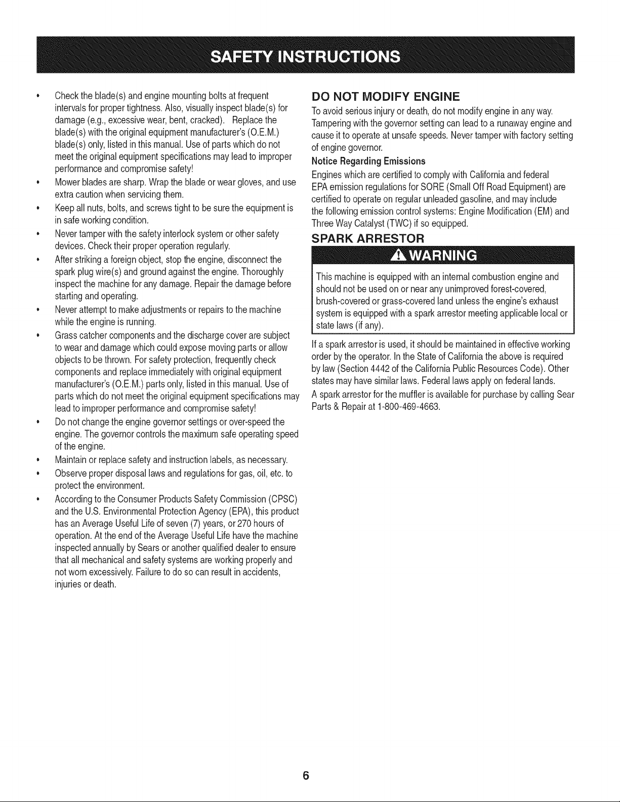
SPARK ARRESTOR
Thismachineis equippedwithan internalcombustionengineand
shouldnot beusedonor nearanyunimprovedforest-covered,
brush-coveredor grass-coveredlandunlessthe engine'sexhaust
systemis equippedwitha sparkarrestormeetingapplicablelocalor
statelaws(if any).
Ifa sparkarrestoris used,it shouldbe maintainedin effectiveworking
orderby the operator.Inthe Stateof Californiatheaboveis required
by law (Section4442of the CaliforniaPublicResourcesCode).Other
statesmayhavesimilarlaws.Federallawsapplyonfederallands.
A sparkarrestorfor the muffleris availablefor purchasebycallingSear
Parts& Repairat 1-800-469-4663.
6
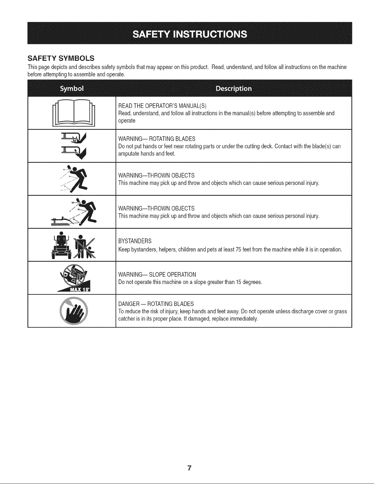
SAFETY SYMBOLS
Thispagedepictsanddescribessafetysymbolsthatmayappearonthis product. Read,understand,andfollowallinstructionson the machine
beforeattemptingto assembleandoperate.
sJ / _
®
READTHEOPERATOR'SMANUAL(S)
Read,understand,andfollowall instructionsinthe manual(s)beforeattemptingto assembleand
operate
WARNING-- ROTATINGBLADES
Donot put handsor feetnearrotatingpartsor underthe cuttingdeck.Contactwiththe blade(s)can
amputatehandsandfeet.
WARNING--THROWNOBJECTS
Thismachinemaypickupandthrowandobjectswhichcancauseseriouspersonalinjury.
WARNING--THROWNOBJECTS
Thismachinemaypickupandthrowandobjectswhichcancauseseriouspersonalinjury.
BYSTANDERS
Keepbystanders,helpers,childrenandpetsat least75feetfromthe machinewhileit is inoperation.
WARNING-- SLOPEOPERATION
Donot operatethismachineona slopegreaterthan 15degrees.
DANGER-- ROTATINGBLADES
To reducethe riskof injury,keephandsandfeetaway.Donotoperateunlessdischargecoveror grass
catcheris in itsproperplace.Ifdamaged,replaceimmediately.
7
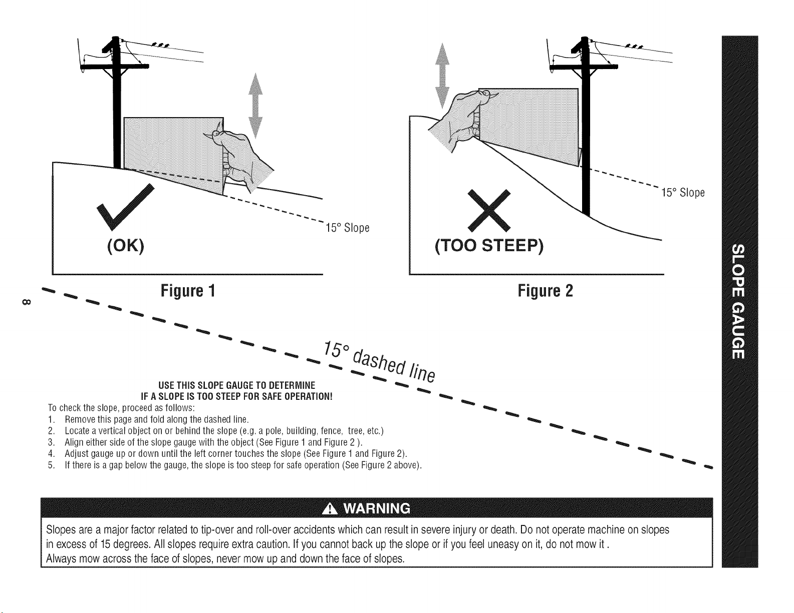
(OK)
15° Slope
X
(TOO STEEP)
15° Slope
'_. _ Figure1
USETHISSLOPEGAUGETODETERMINE
IFA SLOPEIS TOOSTEEPFORSAFEOPERATION!
To checkthe slope,proceedas follows:
1. Removethis pageandfold alongthe dashedline.
2. Locatea verticalobject onor behindthe slope (e.g.a pole, building,fence, tree,etc.)
3. Align eitherside of the slope gaugewith the object(SeeFigure1 and Figure2 ).
4. Adjust gaugeupor down until the left cornertouchesthe slope (SeeFigure1and Figure2).
5.
15°
dashed line
If there is agap belowthe gauge,the slope is too steepfor safeoperation(SeeFigure2 above).
Figure2
Slopes are a majorfactor related to tip-over and roll-over accidents which can result in severe injury or death. Do not operate machine on slopes
in excess of 15 degrees.All slopes require extra caution. If you cannot back up the slope or if you feel uneasy on it, do not mow it.
Always mow across the face of slopes, never mow up and downthe face of slopes.
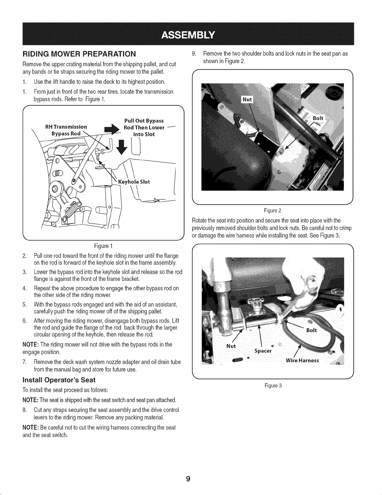
RiDiNG MOWER PREPARATION
Removethe uppercratingmaterialfromthe shippingpallet,andcut
anybandsor tie strapssecuringthe ridingmowerto the pallet.
1. Use the lift handleto raisethedeck to its highestposition.
1. Fromjust in front of thetwo rear tires,locatethe transmission
bypassrods.Referto Figure1.
RH Transmission
Bypass Rod
Figure1
2. Pull one rod towardthe frontof the ridingmoweruntilthe flange
onthe rod is forwardof the keyholeslotin theframeassembly.
3. Lowerthe bypassrod intothe keyholeslot and releaseso the rod
flangeis againstthe frontof the framebracket.
4. Repeattheaboveproceduretoengagethe otherbypassrodon
theother sideof the ridingmower.
5. Withthe bypassrodsengagedandwith the aid of an assistant,
carefullypushthe ridingmoweroff of the shippingpallet.
6. After movingthe ridingmower,disengageboth bypassrods. Lift
the rodandguidethe flangeof the rod backthroughthe larger
circularopeningof the keyhole,then releasethe rod.
NOTE:The ridingmowerwill not drivewiththe bypassrods inthe
engageposition.
7. Removethe deck wash systemnozzleadapterand oil drain tube
fromthe manualbagandstorefor futureuse.
install Operator's Seat
Toinstallthe seatproceedas follows:
NOTE:Theseatisshippedwiththeseatswitchandseatpanattached.
8. Cut anystrapssecuringthe seatassemblyand thedrivecontrol
leversto the ridingmower.Removeanypackingmaterial.
NOTE: Becarefulnotto cut thewiring harnessconnectingthe seat
andthe seatswitch.
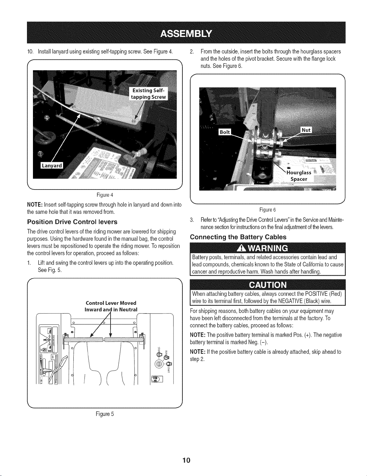
9. Removethe twoshoulderboltsandlocknutsin the seatpanas
showninFigure2.
Figure2
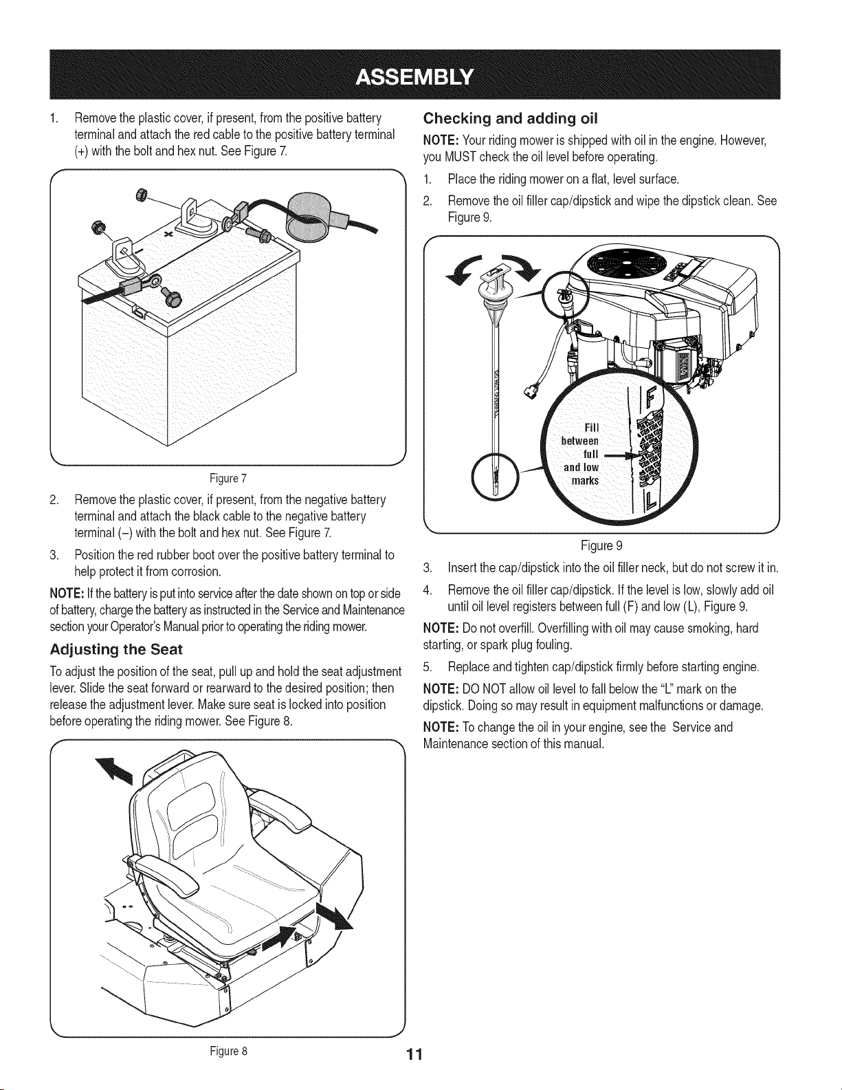
Rotatethe seatintopositionandsecuretheseatinto placewiththe
previouslyremovedshoulderboltsandlocknuts.Becarefulnottocrimp
or damagethewireharnesswhileinstallingthe seat.SeeFigure3.
Figure 3
9
10. Installlanyardusingexistingself-tappingscrew.SeeFigure4. 2. Fromthe outside,insertthe boltsthroughthe hourglassspacers
andthe holesof the pivotbracket.Securewith theflange lock
nuts.SeeFigure6.
Figure4
NOTE: Insertself-tappingscrewthroughholeinlanyardanddowninto
the sameholethatit was removedfrom.
Position Drive Control levers
Thedrivecontrolleversof the ridingmowerareloweredfor shipping
purposes.Usingthe hardwarefoundin the manualbag,the control
leversmustbe repositionedto operatethe ridingmower.To reposition
the controlleversfor operation,proceedas follows:
1. Liftand swingthecontrolleversupinto theoperatingposition.
SeeFig.5.
r
Control Lever Moved
inward and in Neutral
Figure6
3. Referto"AdjustingtheDriveControlLevers"intheServiceandMainte-
nancesectionforinstructionsonthefinaladjustmentofthelevers.
Connecting the Battery Cables
Batteryposts,terminals,and relatedaccessoriescontainleadand
leadcompounds,chemicalsknownto the Stateof Californiato cause
cancerand reproductiveharm.Washhandsafter handling.
Whenattachingbatterycables,alwaysconnectthe POSITIVE(Red)
wireto itsterminalfirst,followedby the NEGATIVE(Black)wire.
Forshippingreasons,bothbatterycableson yourequipmentmay
havebeenleftdisconnectedfromthe terminalsat the factory.To
connectthe batterycables,proceedas follows:
NOTE:Thepositivebatteryterminalis markedPos.(+).The negative
batteryterminalis markedNeg.(-).
NOTE:If the positivebatterycable is alreadyattached,skipaheadto
step2.
Figure5
J
10
Removethe plasticcover,if present,fromthe positivebattery
terminaland attachthe redcableto the positivebatteryterminal
(+)withthe bolt andhexnut.See Figure7.
Figure7
2. Removethe plasticcover,if present,fromthe negativebattery
terminaland attachthe blackcane to the negativebattery
terminal(-) withthe bolt andhex nut.SeeFigure7.
3. Positionthe red rubberbootoverthe positivebatteryterminalto
helpprotectit fromcorrosion.
NOTE:Ifthe batteryisputintoserviceafterthedateshownontoporside
ofbattery,chargethe batteryasinstructedintheServiceandMaintenance
sectionyourOperator'sManualpriorto operatingthe ridingmower.
Adjusting the Seat
Toadjustthe positionof the seat,pullup andholdthe seatadjustment
lever.Slidethe seatforwardor rearwardto the desiredposition;then
releasethe adjustmentlever.Makesureseatis lockedinto position
beforeoperatingthe ridingmower.SeeFigure8.
Checking and adding oil
NOTE: Yourridingmoweris shippedwithoil inthe engine.However,
you MUSTcheckthe oil levelbeforeoperating.
1. Placethe riding moweron a flat,levelsurface.
2. Removethe oilfiller cap/dipstickandwipe thedipstickclean.See
Figure9.
Figure9
3. Insertthe cap/dipstickintothe oil fillerneck,but do notscrewit in.
4. Removethe oilfiller cap/dipstick.If thelevelis low,slowlyaddoil
until oil levelregistersbetweenfull (F) andlow (L), Figure9.
NOTE: Do notoverfill.Overfillingwithoilmaycausesmoking,hard
starting,or sparkplugfouling.
5. Replaceandtightencap/dipstickfirmlybeforestartingengine.
NOTE: DO NOTallowoil levelto fall belowthe "L"markon the
dipstick.Doingso mayresultinequipmentmalfunctionsor damage.
NOTE: Tochangethe oil inyourengine,seethe Serviceand
Maintenancesectionof thismanual.
Figure8 1 1
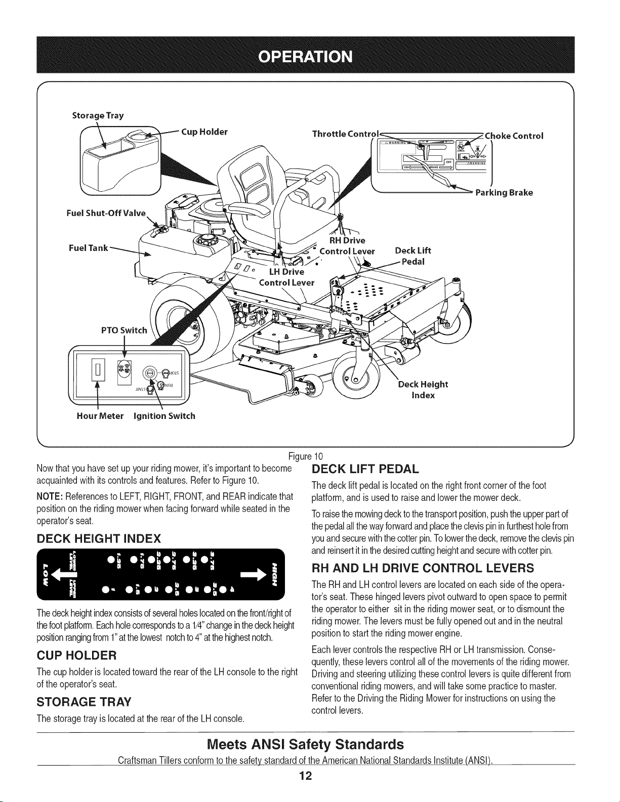
Storage Tray
Cup Holder
Fuel Shut=Off Valve
LH Drive
Control Lever
RH Drive
Control Lever Deck Lift
PTOSwitch
!
HourMeter ignition Switch
Deck Height
index
Figure10
Nowthat youhavesetup yourridingmower,it's importantto become
acquaintedwith itscontrolsandfeatures.Referto Figure10.
NOTE: Referencesto LEFT,RIGHT,FRONT,and REARindicatethat
positiononthe ridingmowerwhenfacingforwardwhile seatedinthe
operator'sseat.
DECK HEIGHT INDEX
DECK LiFT PEDAL
The decklift pedalislocatedon the rightfrontcornerof the foot
platform,andisusedto raiseand lowerthe mowerdeck.
Toraisethemowingdecktothetransportposition,pushtheupperpartof
thepedalallthewayforwardand placetheclevispininfurthestholefrom
youandsecurewiththecotterpin.Tolowerthedeck,removetheclevispin
andreinsertitinthedesiredcuttingheightandsecurewithcotterpin.
RH AND LH DRIVE CONTROL LEVERS
Thedeckheightindexconsistsofseveralholeslocatedon thefront!rightof
thefootplatform.Eachholecorrespondstoa 1/4"changeinthedeckheight
positionrangingfrom1"atthelowestnotchto4"atthehighestnotch.
CUP HOLDER
Thecup holderis locatedtowardthe rearof the LHconsoleto the right
of the operator'sseat.
STORAGE TRAY
The storagetrayis locatedat the rearof the LHconsole.
The RHandLH controlleversarelocatedon eachsideof the opera-
tor's seat.Thesehingedleverspivotoutwardto open spaceto permit
the operatorto either sit in the ridingmowerseat,or to dismountthe
ridingmower.Theleversmust befullyopenedoutand inthe neutral
positionto startthe ridingmowerengine.
Eachlevercontrolsthe respectiveRHorLH transmission.Conse-
quently,theseleverscontrolallof the movementsof the ridingmower.
Drivingand steeringutilizingthesecontrolleversis quitedifferentfrom
conventionalridingmowers,andwill takesomepracticeto master.
Referto the Drivingthe RidingMowerfor instructionson usingthe
controllevers.
Meets ANSI Safety Standards
CraftsmanTillersconformto the safetystandardof the AmericanNationalStandardsInstitute(ANSI)
12
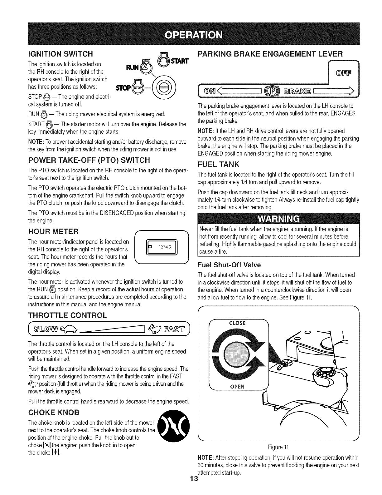
iGNiTiON SWITCH
Theignitionswitchis locatedon
the RHconsoleto the rightof the
operator'sseat.Theignitionswitch
hasthree positionsas follows:
STOP_ -- The engineandelectri-
cal systemis turnedoff.
RUN_-- Theridingmowerelectricalsystemis energized.
START_ -- The startermotor willturn overthe engine.Releasethe
keyimmediatelywhenthe enginestarts
NOTE:To preventaccidentalstartingand/orbatterydischarge,remove
thekeyfromtheignitionswitchwhenthe ridingmoweris notinuse.
POWER TAKE-OFF (PTO) SWITCH
The PTOswitchis locatedonthe RHconsoleto the rightof the opera-
tot's seatnextto the ignitionswitch.
The PTOswitchoperatesthe electricPTOclutchmountedonthe bot-
tomof the enginecrankshaft.Pullthe switchknobupwardto engage
the PTOclutch,or pushthe knobdownwardto disengagethe clutch.
The PTOswitchmustbein the DISENGAGEDpositionwhenstarting
the engine.
HOO.O.T.. '11
Thehourmeter/indicatorpanelis locatedon
the RHconsoleto the rightof the operator's 1234.5
seat.The hourmeterrecordsthe hoursthat
the ridingmowerhas beenoperatedin the
digitaldisplay.
Thehourmeteris activatedwheneverthe ignitionswitchis turnedto
the RUN_ position.Keepa recordof the actualhoursof operation
to assureall maintenanceproceduresarecompletedaccordingto the
instructionsin thismanualandthe enginemanual.
THROTTLE CONTROL
Thethrottlecontrolis locatedon the LHconsoleto the leftof the
operator'sseat.Whensetina givenposition,a uniformenginespeed
will bemaintained.
Pushthethrottlecontrolhandleforwardto increasetheenginespeed.The
ridingmowerisdesignedto operatewiththethrottlecontrolin theFAST
_;? position(fullthrottle)whentheridingmowerisbeingdrivenandthe
mowerdeckisengaged.
Pullthethrottlecontrolhandlerearwardto decreasethe enginespeed.
CHOKE KNOB
Thechokeknobis locatedonthe left sideof the mower
nextto the operator'sseat.The chokeknobcontrolsthe
positionof the enginechoke.Pullthe knobout to
chokeI'_,1the engine;pushthe knob in to open
the chokeI JtI.
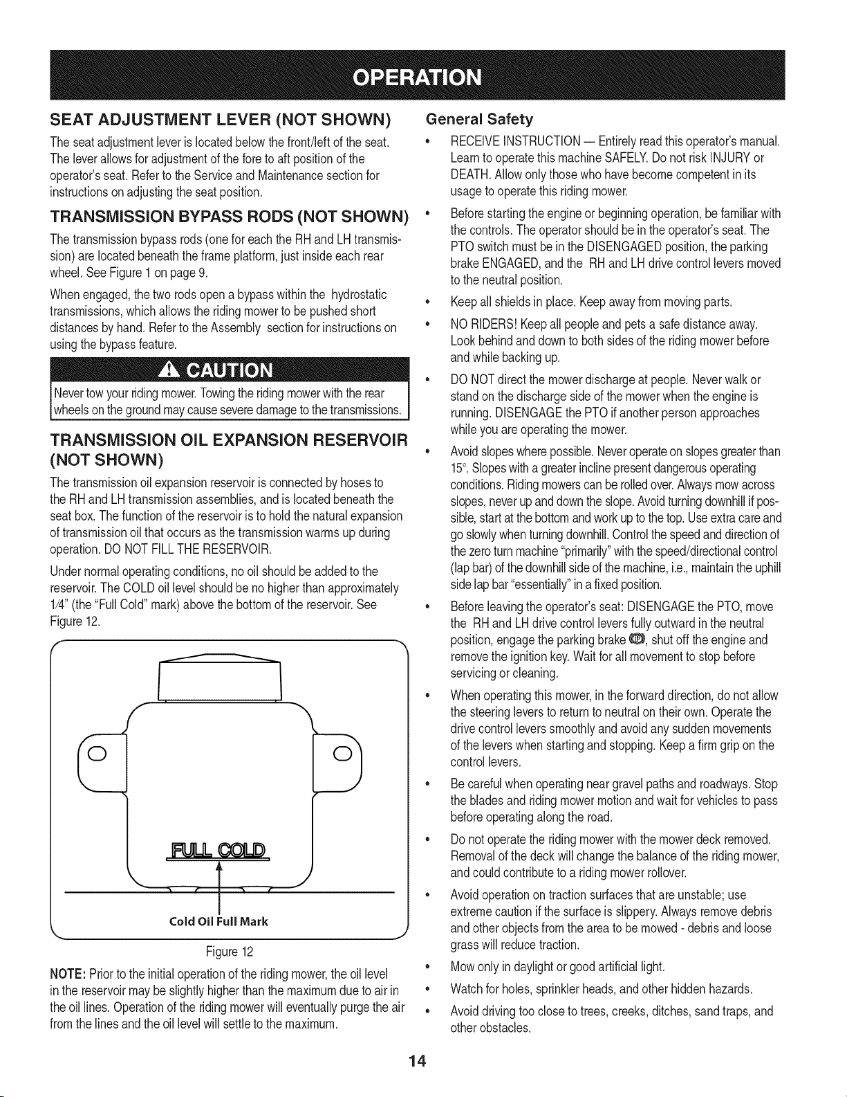
PARKING BRAKE ENGAGEMENT LEVER
(®=< ,{@) =,, >
The parkingbrakeengagementleveris locatedon the LHconsoleto
the leftof theoperator'sseat,andwhenpulledto the rear,ENGAGES
the parkingbrake.
NOTE:if the LHand RHdrivecontrolleversarenot fullyopened
outwardto each sideinthe neutralpositionwhenengagingthe parking
brake,the enginewill stop.Theparkingbrakemustbeplacedin the
ENGAGEDpositionwhenstartingthe ridingmowerengine.
FUEL TANK
The fueltankis locatedto the rightof the operator'sseat.Turnthe fill
cap approximately1/4turn andpullupwardto remove.
Pushthe cap downwardon the fueltank fill neckandturn approxi-
mately1/4turnclockwiseto tightenAlwaysre-instalthe fuel captightly
onto thefuel tankafterremoving.
Neverfill the fuel tankwhenthe engineis running,if the engineis
hot fromrecentlyrunning,allowto cool for severalminutesbefore
refueling.Highlyflammablegasolinesplashingonto theenginecould
_causea f re.
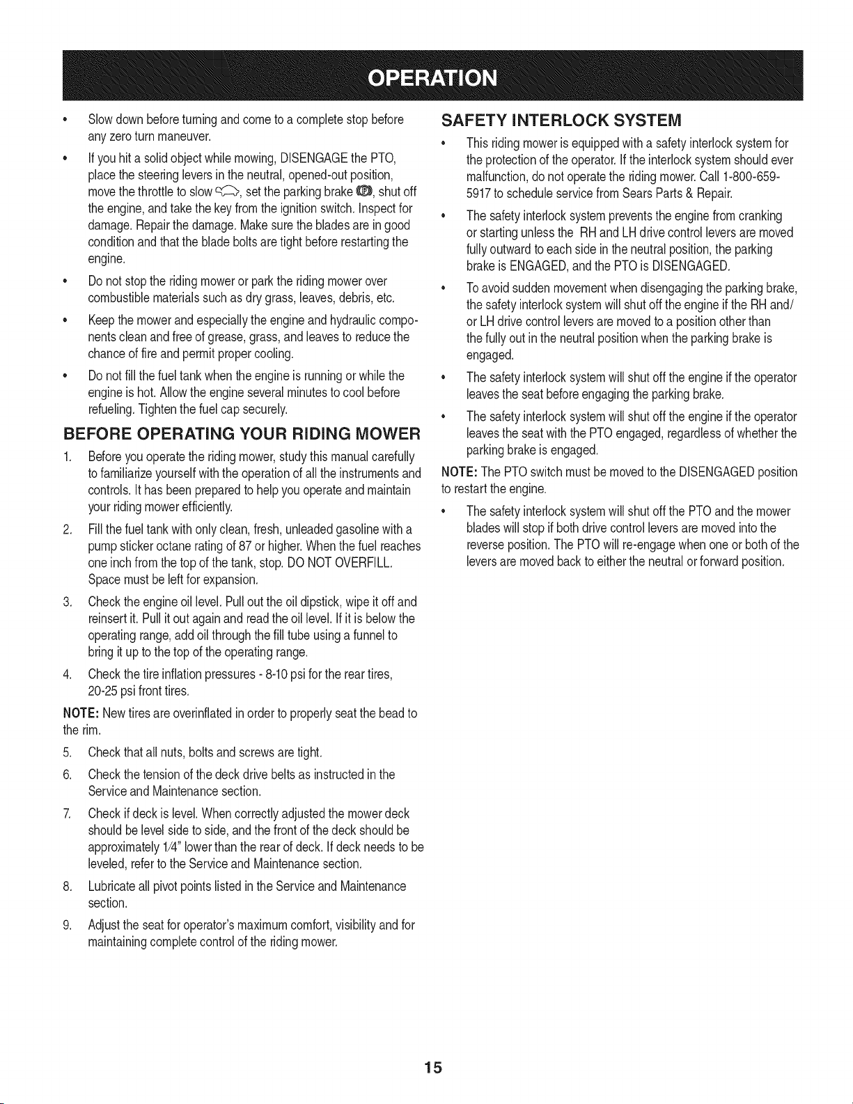
Fuel Shut=Off Valve
The fuelshut-offvalveislocatedontop of the fuel tank.Whenturned
ina clockwisedirectionuntilitstops,itwill shutoffthe flowof fuel to
the engine.Whenturnedinacounterclockwisedirectionitwill open
andallowfuel to flowto the engine.SeeFigure11.
CLOSE
OPEN
Figure11
NOTE:Afterstoppingoperation,if youwill not resumeoperationwithin
30 minutes,closethisvalveto preventfloodingthe engineonyour next
attemptedstart-up.
13
SEAT ADJUSTMENT LEVER (NOT SHOWN)
The seatadjustmentleveris locatedbelowthefront/leftof the seat.
The leverallowsfor adjustmentof the foreto aft positionof the
operator'sseat.Referto the ServiceandMaintenancesectionfor
instructionsonadjustingthe seatposition.
TRANSMISSION BYPASS RODS (NOT SHOWN)
Thetransmissionbypassrods(onefor eachthe RHandLH transmis-
sion)are locatedbeneaththe frameplatform,just insideeach rear
wheel.SeeFigure1on page9.
Whenengaged,the two rodsopena bypasswithinthe hydrostatic
transmissions,whichallowsthe ridingmowerto be pushedshort
distancesby hand. Referto the Assembly sectionfor instructionson
usingthe bypassfeature.
Nevertowyourridingmower.Towingtheridingmowerwith the rear
wheelsonthegroundmaycauseseveredamageto thetransmissions.
TRANSMISSION OIL EXPANSION RESERVOIR
(NOT SHOWN)
Thetransmissionoil expansionreservoiris connectedby hosesto
the RHandLHtransmissionassemblies,and is locatedbeneaththe
seatbox.The functionof the reservoiris to holdthe naturalexpansion
of transmissionoilthatoccursas the transmissionwarmsup during
operation.DO NOTFILLTHE RESERVOIR.
Undernormaloperatingconditions,nooil shouldbeaddedto the
reservoir.The COLDoil levelshouldbe nohigherthan approximately
1/4"(the"Full Cold"mark)abovethe bottomof the reservoir.See
Figure12.
General Safety
• RECEIVEINSTRUCTION-- Entirelyreadthisoperator'smanual.
Learnto operatethismachineSAFELY.Do not riskINJURYor
DEATH.Allowonlythosewho havebecomecompetentin its
usageto operatethis ridingmower.
• Beforestartingthe engineor beginningoperation,be familiarwith
the controls.Theoperatorshouldbein the operator'sseat.The
PTOswitchmustbein the DISENGAGEDposition,the parking
brakeENGAGED,andthe RHand LHdrivecontrolleversmoved
to the neutralposition.
• Keepall shieldsin place. Keepawayfrom movingparts.
• NORIDERS!Keepall peopleand pets a safedistanceaway.
Lookbehindand downto bothsidesof the ridingmowerbefore
andwhile backingup.
• DONOTdirect the mowerdischargeat people.Neverwalkor
standonthe dischargesideof the mowerwhentheengineis
running.DISENGAGEthe PTOif anotherpersonapproaches
whileyou areoperatingthe mower.
• Avoidslopeswherepossible.Neveroperateonslopesgreaterthan
15°.Slopeswitha greaterinclinepresentdangerousoperating
conditions.Ridingmowerscan berolledover.Alwaysmowacross
slopes,neverupanddownthe slope.Avoidturningdownhillif pos-
sible,startat thebottomandworkupto thetop.Useextracareand
go slowlywhenturningdownhill.Controlthe speedanddirectionof
the zeroturnmachine"primarily"with thespeed/directionalcontrol
(lapbar)of thedownhillsideof themachine,i.e.,maintainthe uphill
sidelapbar"essentially"in afixedposition.
• Beforeleavingthe operator'sseat:DISENGAGEthe PTO,move
the RHand LHdrivecontrolleversfullyoutwardin the neutral
position,engagethe parkingbrake0, shutoff the engineand
removethe ignitionkey.Waitfor all movementto stopbefore
servicingor cleaning.
• Whenoperatingthis mower,in the forwarddirection,do notallow
the steeringleversto returnto neutralon theirown.Operatethe
drivecontrolleverssmoothlyandavoidany suddenmovements
of the leverswhen startingandstopping.Keepa firmgripon the
controllevers.
' • ..... • 3 ..... f
ColdOilFull Mark
Figure12
NOTE: Priorto the initialoperationof the ridingmower,the oil level
inthe reservoirmaybeslightlyhigherthanthe maximumdueto air in
theoil lines.Operationof the ridingmowerwilleventuallypurgethe air
fromthe lines andtheoil levelwill settleto the maximum.
• Be carefulwhenoperatingneargravelpathsand roadways.Stop
the bladesandridingmowermotionandwaitfor vehiclesto pass
beforeoperatingalongthe road.
• Donot operatethe riding mowerwith the mowerdeckremoved.
Removalof the deckwillchangethe balanced the ridingmower,
andcouldcontributeto a ridingmowerrollover.
Avoidoperationontractionsurfacesthatare unstable;use
extremecautionif the surfaceis slippery.Alwaysremovedebris
andotherobjectsfromthe areato bemowed- debrisandloose
grasswill reducetraction.
• Mowonly in daylightor good artificiallight.
• Watchfor holes,sprinklerheads,andother hiddenhazards.
• Avoiddrivingtoocloseto trees,creeks,ditches,sandtraps,and
otherobstacles.
14
• Slowdownbeforeturningand come toa completestop before
anyzeroturn maneuver.
• If youhit a solidobjectwhilemowing,DISENGAGEthe PTO,
placethe steeringleversinthe neutral,opened-outposition,
movethe throttleto slowq?::>,setthe parkingbrake8, shutoff
the engine,andtakethe keyfromthe ignitionswitch.Inspectfor
damage.Repairthe damage.Makesurethe bladesarein good
conditionandthatthe bladeboltsare tightbeforerestartingthe
engine.
• Do not stopthe ridingmoweror parkthe ridingmowerover
combustiblematerialssuchas dry grass,leaves,debris,etc.
• Keepthe mowerandespeciallytheengine and hydrauliccompo-
nentscleanandfree of grease,grass,and leavesto reducethe
chanceof fire andpermitpropercooling.
• Do notfill the fuel tankwhen theengineis runningorwhilethe
engineis hot.Allowthe engineseveralminutesto cool before
refueling.Tightenthe fuelcap securely.
BEFORE OPERATING YOUR RIDING MOWER
1. Beforeyou operatethe ridingmower,studythismanualcarefully
to familiarizeyourselfwiththe operationof allthe instrumentsand
controls.Ithas beenpreparedto helpyouoperateand maintain
yourridingmowerefficiently.
2. Fill thefuel tank with onlyclean, fresh,unleadedgasolinewith a
pumpstickeroctaneratingof 87or higher.Whenthe fuel reaches
oneinchfromthe top of the tank,stop.DO NOTOVERFILL.
Spacemustbeleftfor expansion.
3. Checktheengineoil level. Pullout the oil dipstick,wipeit off and
reinsertit. Pullit out againand readthe oillevel.Ifit is belowthe
operatingrange,addoil throughthe fill tube usinga funnelto
bringit upto the top of the operatingrange.
4. Checkthetire inflationpressures-8-10psi for the rear tires,
20-25psi fronttires.
NOTE: Newtiresareoverinflatedinorderto properlyseatthe beadto
the rim.
5. Checkthatall nuts,bolts and screwsare tight.
6. Checkthetensionof the deck drivebelts as instructedin the
ServiceandMaintenancesection.
7. Checkif deck is level.Whencorrectlyadjustedthe mowerdeck
shouldbelevelside to side,andthe frontof the deckshouldbe
approximately1/4"lowerthanthe rearof deck.If deckneedsto be
leveled,referto the Serviceand Maintenancesection.
8. Lubricateall pivotpoints listedin the Serviceand Maintenance
section.
9. Adjustthe seat foroperator'smaximumcomfort,visibilityandfor
maintainingcompletecontrolof the ridingmower.
SAFETY INTERLOCK SYSTEM
• This ridingmoweris equippedwitha safetyinterlocksystemfor
the protectionof the operator.Ifthe interlocksystemshouldever
malfunction,do not operatethe ridingmower.Call 1-800-659-
5917to scheduleservicefromSearsParts& Repair.
• The safetyinterlocksystempreventsthe enginefrom cranking
or startingunlessthe RH andLH drivecontrolleversare moved
fullyoutwardto eachside inthe neutralposition,the parking
brakeis ENGAGED,and the PTOis DISENGAGED.
• Toavoidsuddenmovementwhendisengagingthe parkingbrake,
the safetyinterlocksystemwill shutoff the engineif the RHand/
or LH drivecontrolleversaremovedto a positionotherthan
the fullyout inthe neutralpositionwhenthe parkingbrakeis
engaged.
• The safetyinterlocksystemwill shut off theengine if the operator
leavesthe seatbeforeengagingthe parkingbrake.
• The safetyinterlocksystemwill shut off theengine if the operator
leavesthe seatwiththe PTOengaged,regardlessof whetherthe
parkingbrakeis engaged.
NOTE:The PTOswitchmustbemovedto the DISENGAGEDposition
to restartthe engine.
• The safetyinterlocksystemwill shut off the PTOand the mower
bladeswill stopif bothdrive controlleversaremovedintothe
reverseposition.The PTOwill re-engagewhen oneorbothof the
leversare movedbackto eitherthe neutralor forwardposition.
15
STARTING THE ENGINE
Thisridingmoweris equippedwitha safetyinterlocksystem
designedforthe protectionof the operator.Do notoperatethe riding
mowerif any partof the interlocksystemis malfunctioning.Periodi-
_cay checkthefunctons of the nterock systemfor properoperaton.
Forpersonalsafety,the operatormustbe sittinginthe ridingmower
seatwhen startingthe engine.
.
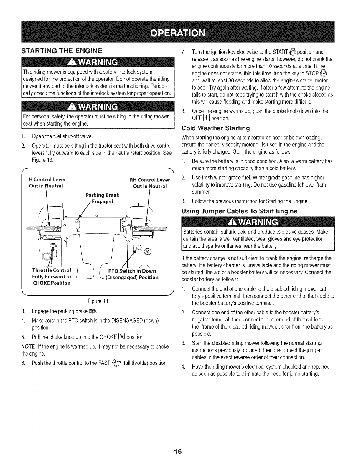
2.
Openthe fuel shut-offvalve.
Operatormustbesittingin the tractorseatwith bothdrivecontrol
leversfullyoutwardto eachside inthe neutral/startposition.See
Figure13.
LHControlLever
Out in !eutral
CHOKE Position
Parking Break
Engaged
RH Control Lever
Out in Neutral
J
Figure13
3. EngagetheparkingbrakeO.
4. Makecertainthe PTOswitchis in the DISENGAGED(down)
position.
5. Pull the chokeknobup intothe CHOKE!'_.1position.
NOTE: Ifthe engineis warmedup, it maynotbe necessaryto choke
theengine.
6. Pushthe throttlecontrolto the FAST_ (full throttle)position.
7. Turnthe ignitionkey clockwiseto the START_ positionand
releaseit as soonas the enginestarts; however,do notcrankthe
enginecontinuouslyfor morethan 10secondsat a time. Ifthe
enginedoes not startwithinthis time,turnthe keyto STOP
andwaitat least30 secondsto allowthe engine'sstartermotor
to cool.Tryagainafterwaiting.Ifaftera fewattemptsthe engine
failsto start,do not keeptryingto startit withthe chokeclosedas
this willcausefloodingandmakestartingmoredifficult.
8. Once theenginewarmsup, pushthechoke knobdownintothe
OFFI { ! position.
Cold Weather Starting
Whenstartingthe engineat temperaturesnearor belowfreezing,
ensurethecorrectviscositymotoroil is used inthe engineandthe
batteryis fullycharged.Startthe engineas follows:
1. Be surethe batteryis in good condition.Also,a warm batteryhas
muchmorestartingcapacitythana coldbattery.
2. Usefreshwintergradefuel.Wintergradegasolinehas higher
volatilityto improvestarting.Do notuse gasolineleftoverfrom
summer.
3. Followthe previousinstructionfor Startingthe Engine.
Using Jumper Cables To Start Engine
Batteriescontainsulfuricacidandproduceexplosivegasses.Make
certainthe areais well ventilated,wearglovesandeye protection,
land avod sparksorf amesnearthe battery.
Ifthe batterychargeis notsufficientto crankthe engine,rechargethe
battery.If a batterychargeris unavailableandthe ridingmowermust
be started,the aidof a boosterbatterywill be necessary.Connectthe
boosterbatteryas follows:
1. Connecttheendof one cableto thedisabledridingmowerbat-
tery's positiveterminal;thenconnecttheotherendof thatcableto
the boosterbattery'spositiveterminal.
2. Connectone endof the othercableto the boosterbattery's
negativeterminal;thenconnecttheother endof thatcableto
the frame of the disabledriding mower,as far fromthe batteryas
possible.
3. Start the disabledridingmowerfollowingthe normalstarting
instructionspreviouslyprovided;thendisconnectthejumper
cablesinthe exactreverseorderof theirconnection.
4. Havethe ridingmower'selectricalsystemcheckedandrepaired
as soonas possibleto eliminatethe needforjump starting.
16
Stopping the Engine
1. Pushthe PTOswitchdownintothe DISENGAGEDposition.
2. Movethe RH and LH drivecontrolleversoutwardto the neutral
position.
3. Engagethe parkingbrakeO.
4. Movethe throttlecontrol to midwaybetweenthe SLOW_ and
FAST_ positions.
5. Turnthe ignitionkeyto the STOP6 positionand removethe key
fromthe ignitionswitch.
NOTE:Alwaysremovethe keyfromthe ignitionswitchto preventacci-
dentalstartingor batterydischargeif the equipmentis Idt unattended.
PRACTICE OPERATION (INITIAL USE)
Operatinga zero-turnridingmoweris notlikeoperatinga conventional
typeridingmower.Becausea zeroturn ridingmoweris moremaneuver-
able,gettingusedto operatingthecontrolleverstakessomepractice.
Westronglyrecommendthatyou locatea reasonablylarge,leveland
open"practicearea"wheretherearenoobstructions,pedestrians,or
animals.Youshouldpracticeoperatingthe riding mowerfor a minimum
of 30 minutes.
Carefullymove-- or haveanexperiencedusermove-- the riding
mowerto the practicearea.Whenperformingthe practicesession,
the PTOshouldnot beengaged.Whilepracticing,operatethe riding
mowerat approximately1/2to 3/4throttleandat lessthanfull speedin
bothforwardandreverse.
Useprotectiveequipmentforeyes,hands,hearing,feet, legs,head
andotherareasof the bodyif needed-- safetyeyeglasses,gloves,
earplugs,boots,hats,etc.
HearingProtectionis requiredfor alloperatorexposureexceeding
two(2) hours.
Carefullypracticemaneuveringthe ridingmowerusingthe instructions
in thefollowingsection"Drivingthe Ridingmower."Practiceuntil you
areconfidentthatyoucan safelyoperatethe ridingmower.
DRIVING THE RIDING MOWER
Avoidsuddenstarts,excessivespeedand suddenstops.
1. Adjusttheoperator'sseatto the mostcomfortablepositionthat
allowsyou to operatethe controls.Seeseatadjustmentinthe
Assemblysection.
2. ReleasetheparkingbrakeO.
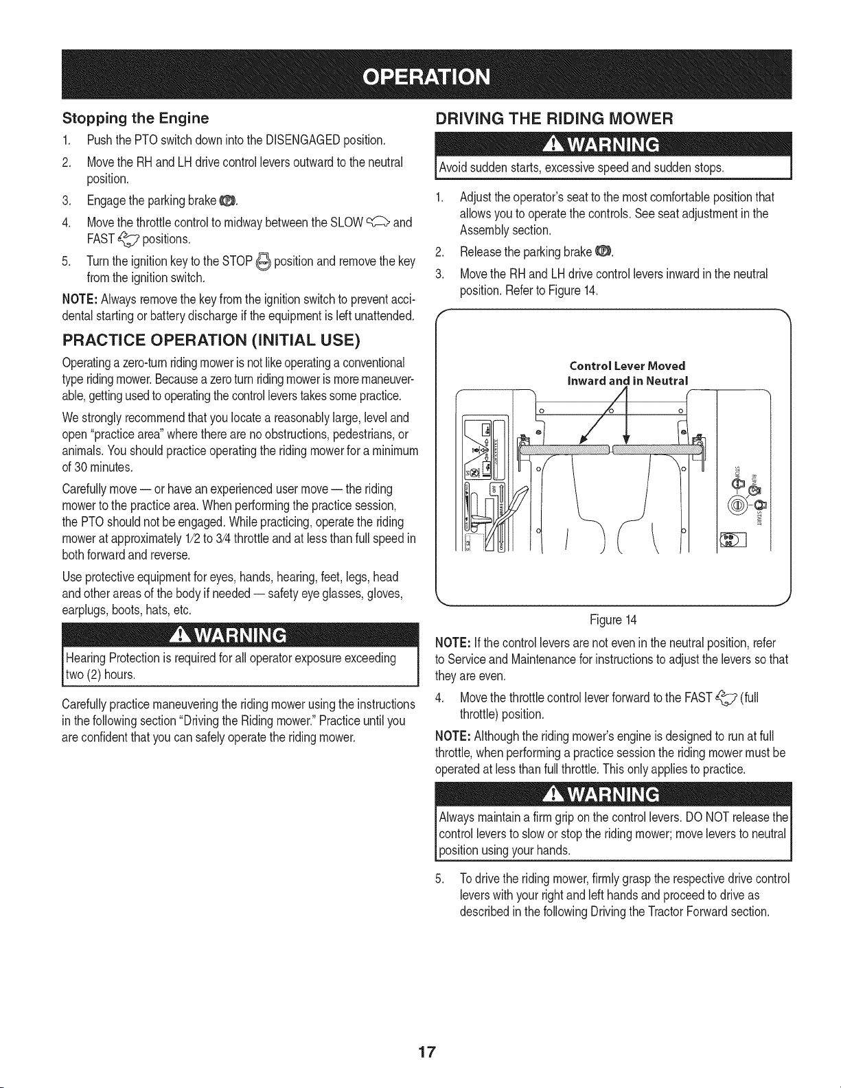
3. Movethe RHand LHdrivecontrolleversinwardin the neutral
position.Referto Figure14.
ControlLeverMoved
inwardand in Neutral
o
/
Figure14
NOTE:If thecontrolleversarenotevenin the neutralposition,refer
to Serviceand Maintenancefor instructionsto adjustthe leverssothat
theyareeven.
4. Movethe throttlecontrolleverforwardto the FAST_ (full
throttle)position.
NOTE:Althoughthe ridingmower'sengineis designedto runat full
throttle,whenperforminga practicesessionthe ridingmowermustbe
operatedat lessthan fullthrottle.Thisonly appliesto practice.
usingyourhands.
Todrive the ridingmower,firmlygraspthe respectivedrive control
leverswithyour rightandleft handsand proceedto driveas
describedinthe followingDrivingthe TractorForwardsection.
17
Driving the Riding Mower Forward
Keepall movementof the drivecontrolleversslowandsmooth.
Abruptmovementof the controlleverscan affectthe stabilityof the
ridingmowerandcouldcausethe ridingmowerto flip over,which
mayresultin seriousinjuryordeathto the operator.
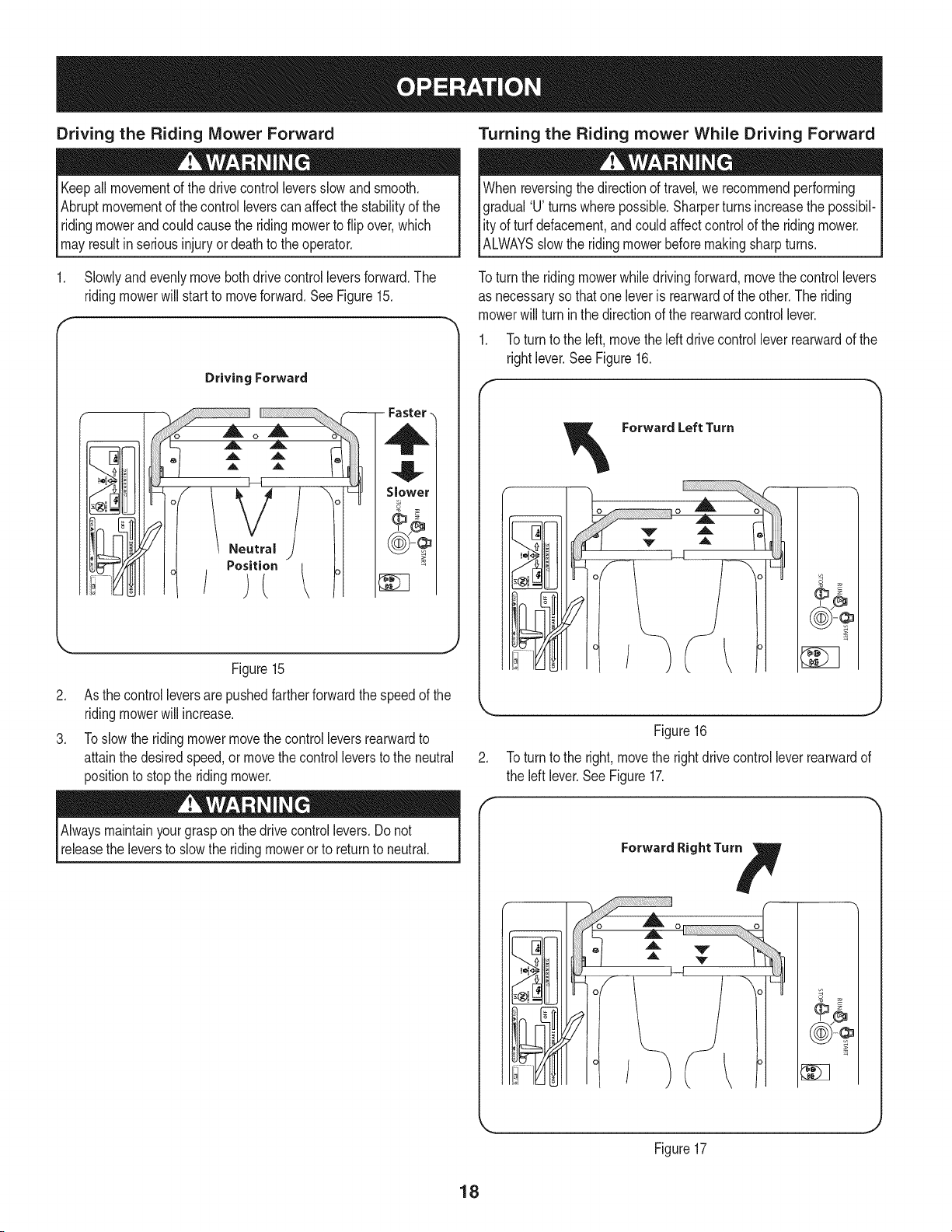
1. Slowlyand evenlymovebothdrivecontrol leversforward.The
ridingmowerwill start to moveforward.SeeFigure15.
J/A
Driving Forward
¢
o
_. ,A A _'-_/
_,t ,,L A t,,I I I
t A ,,, h
\ Neutral ) 1
/.o?,.,i°i ,
- Faster -
S, w:r
.
.
Figure15
As thecontrolleversarepushedfartherforwardthe speedof the
ridingmowerwill increase.
Toslowthe ridingmowermovethe controlleversrearwardto
attainthe desiredspeed,ormovethecontrolleverstothe neutral
positionto stopthe ridingmower.
Alwaysmaintainyourgraspon the drivecontrollevers.Donot
releasethe leversto slowthe ridingmowerorto returnto neutral.
Turning the Riding mower While Driving Forward
When reversingthe directionof travel,we recommendperforming
gradual'U turns wherepossible.Sharperturns increasethe possibil-
ity of turfdefacement,andcouldaffectcontrolof the ridingmower.
IALWAYSsow the rd ngmowerbeforemakng sharpturns.
Toturn the ridingmowerwhiledrivingforward,movethe controllevers
as necessaryso thatone leveris rearwardof theother.The riding
mowerwill turn inthe directionof the rearwardcontrollever.
1. Toturn to the left, movethe leftdrivecontrollever rearwardof the
rightlever.SeeFigure16.
Forward Left Turn
o
.
Figure16
Toturn to the right,movethe rightdrivecontrolleverrearwardof
the left lever.See Figure17.
Forward Right Tur_
0 '
J
_ J
Figure17
18
NOTE:The greaterthe fore-to-aftdistancebetweenthe twolevers,the
sharperthe ridingmowerwill turn.
3. Toexecutea "zeroturn,"movethe turnside drivecontrolleverto
the neutralposition,while movingthe othercontrolleverforward.
NOTE: Makinga "zeroturn"on grasswill greatlyincreasethepotential
for defacementof the turf.
Driving the Riding mower in Reverse
Alwayslookbehindanddownonbothsidesof theridingmowerbefore
backingup.Alwayslookbehindwhiletravelinginthe reversedirection.
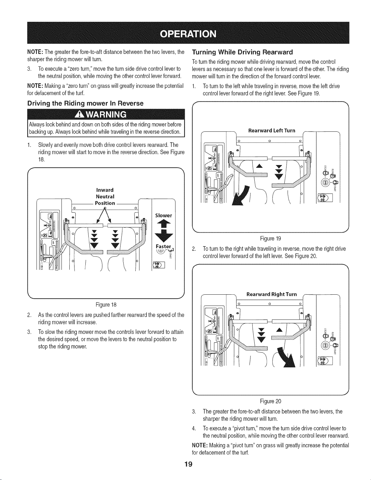
1. Slowlyand evenlymovebothdrive controlleversrearward.The
ridingmowerwill startto movein the reversedirection.SeeFigure
18.
o
inward
Neutral
_ Position o_
Slower
Faster
Turning While Driving Rearward
Toturn the ridingmowerwhiledriving rearward,movethe control
leversas necessaryso thatoneleverisforwardof the other.Theriding
mowerwill turn inthe directionof the forwardcontrollever.
1. Toturn to the leftwhiletravelingin reverse,movethe leftdrive
controlleverforwardof the right lever.See Figure19.
RearwardLeftTurn
o
Figure19
2. Toturn to the rightwhiletravelingin reverse,movethe rightdrive
controlleverforwardof the left lever.See Figure20.
.
.
Figure18
As thecontrolleversarepushedfartherrearwardthe speedof the
ridingmowerwill increase.
Toslowthe ridingmowermovethe controlsleverforwardto attain
the desiredspeed,or movethe leversto the neutralpositionto
stopthe ridingmower.
m
II ,.-,'qII
J
Figure20
3. The greaterthe fore-to-aftdistancebetweenthe two levers,the
sharperthe ridingmowerwill turn.
4. Toexecutea "pivotturn,"movethe turn sidedrivecontrolleverto
the neutralposition,whilemovingthe othercontrolleverrearward.
NOTE:Makinga"pivotturn"on grasswill greatlyincreasethe potential
for defacementof theturf.
19
Executing a Zero Turn
Whenexecutinga zeroturn,the ridingmowerMUSTBESTOPPED.
Executinga zeroturn whilethe ridingmoweris movingcan signifi-
Icantlyreduceyourcontrolof the ridingmowerandwill causesevere
[turf defacementto occur.
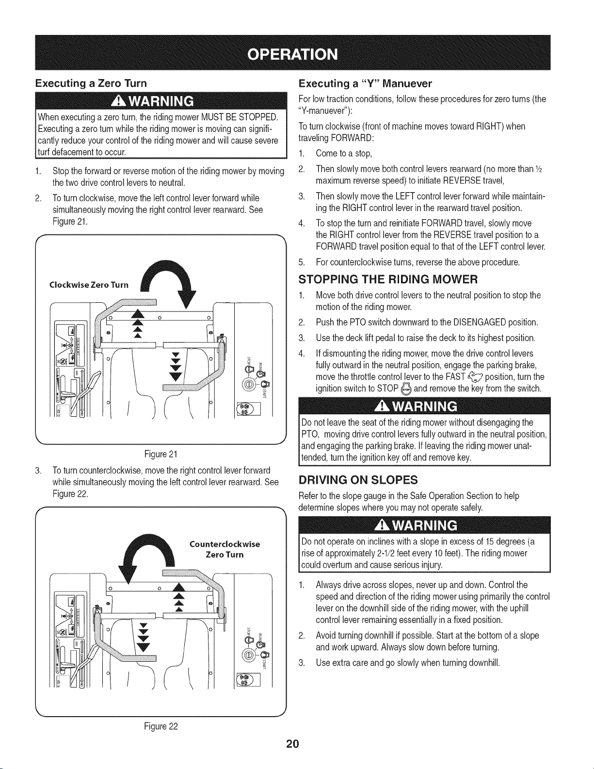
1. Stopthe forwardor reversemotionof the riding mowerby moving
thetwo drivecontrolleversto neutral.
2. Toturnclockwise,movethe left controlleverforwardwhile
simultaneouslymovingthe rightcontrolleverrearward.See
Figure21.
Clockwise Zero Turn
.
Figure21
Toturncounterclockwise,movethe rightcontrolleverforward
whilesimultaneouslymovingthe leftcontrolleverrearward.See
Figure22.
Executing a "Y" Manuever
Forlowtractionconditions,followtheseproceduresfor zeroturns(the
"Y-manuever"):
Toturn clockwise(frontof machinemovestowardRIGHT)when
travelingFORWARD:
1. Cometoa stop,
2. Then slowlymove bothcontrolleversrearward(no morethan 1/2
maximumreversespeed)to initiateREVERSEtravel,
3. Then slowlymovethe LEFTcontrol leverforwardwhile maintain-
ingthe RIGHTcontrolleverinthe rearwardtravelposition.
4. To stopthe turnand reinitiateFORWARDtravel,slowlymove
the RIGHTcontrolleverfromthe REVERSEtravelpositionto a
FORWARDtravelpositionequalto thatof the LEFTcontrollever.
5. Forcounterclockwiseturns, reversethe aboveprocedure.
STOPPING THE RIDING MOWER
1. Movebothdrivecontrolleversto the neutralpositionto stop the
motionof the ridingmower.
2. Pushthe PTOswitchdownwardto the DISENGAGEDposition.
3. Usethe decklift pedalto raisethe deck to itshighestposition.
4. Ifdismountingthe ridingmower,movethe drivecontrollevers
fullyoutwardin the neutralposition,engagethe parkingbrake,
movethethrottlecontrolleverto the FAST_ position,turnthe
ignitionswitchto STOP_ and removethe keyfromthe switch.
Donot leavethe seatof the ridingmowerwithoutdisengagingthe
PTO, movingdrivecontrolleversfullyoutwardinthe neutralposition,
land engagingthe parkingbrake.If leavingthe ridingmowerunat-
ltended,turnthe ignitionkeyoffand removekey.
DRIVING ON SLOPES
Referto the slopegaugeinthe Safe OperationSectionto help
determineslopeswhereyou maynotoperatesafely.
_uL
I 1 _'-III
/
Counterclockwise
Zero Turn
o
((¢))-@
Donot operateoninclineswitha slope inexcessof 15degrees(a
riseof approximately2-1/2feet every 10feet).The ridingmower
couldoverturnandcauseseriousinjury.
1. Alwaysdriveacrossslopes,neverup anddown.Controlthe
speedanddirectionof the ridingmowerusingprimarilythecontrol
leveron thedownhillsideof the ridingmower,withthe uphill
controlleverremainingessentiallyina fixedposition.
2. Avoidturningdownhillif possible.Start at the bottomof a slope
andworkupward.Alwaysslowdown beforeturning.
3. Useextracareandgo slowlywhen turningdownhill.
Figure22
2O
OPERATING THE PTO
1. OperatethePTOclutchasfollows:
2. Movethe throttlecontrol leverto approximatelythe midthrottle
position.
3. Pull the PTOswitchupwardto the ENGAGEDposition.
4. Advancethe throttleleverto the FAST_ position.
NOTE:The operatormustremainin the ridingmowerseatat all times.
If theoperatorshouldleavethe seatwithoutturningoff the power
take-offswitch,the ridingmower'senginewill shutoff.
NOTE:The PTOcannotbeoperatedwhenthe ridingmoweris driving
in the reversedirection.The PTOwill disengagewhen bothdrive
controlleversaremovedto the reverseposition,and will re-engage
whenone(or both)controllever(s)is movedto the neutralor forward
position.
USING THE MOWER DECK
Makecertainthe areato be mowedis free of debris,sticks,stones,
wireor otherobjectsthatcan bethrownbythe rotatingblades.
NOTE:Do notengagethe mowerdeckwhenloweredingrass.
Prematurewearandpossiblefailureof the 'V" beltandPTOclutch
will result.Fullyraisethe deckor moveto anon-grassyareabefore
engagingthe mowerdeck.
1. Mowacrossslopes,notup anddown.Ifmowinga slope,startat
bottomand workupwardto ensureturnsare madeuphill.
2. On the first pass picka pointon the oppositeside of the areato
bemowed.
3. Engagethe PTOand movethe throttlecontrolto the FAST
position.
4. Lowerthe mowerdeck to the desiredheightsettingusingthe
decklift handle.
5. Slowlyand evenlypushthe RH and LH drivecontrollevers
forwardto movethe ridingmowerforward,andkeepthe riding
mowerheadeddirectlytowardthe alignmentpoint.
NOTE:The speedof the ridingmowerwill affectthe qualityof the
mowercut. Mowingat full speedwilladverselyaffectthecut quality.
Controlthegroundspeedwiththe controllevers.
6. Whenapproachingthe otherend of the strip,slow downor stop
beforeturning.A U-turnis recommendedunlessa zeroturn is
required.
7. Align themowerwith an edge of the mowedstrip and overlap
approximately3".
8. Directthe ridingmoweron each subsequentstrip to alignwith a
previouslycut strip.
9. To preventruttingor groovingof the turf, ifpossible,changethe
directionthatthe stripsaremowedby approximately450forthe
nextandeach subsequentmowing.
Becarefulwhencrossinggravelpathsordriveways.Disengagethe
PTOand raisethe deckto the highestpositionbeforecrossing.
NOTE:Whenstoppingthe ridingmowerfor any reasonwhileon a
grasssurface,always:
• Placethe shift leverin neutral,
• Engagethe parkingbrake8,
• Shutengineoff and removethe key.
• Doingso will minimizethe possibilityof havingyour lawn
"browned"by hotexhaustfromyour ridingmower'srunning
engine.
CHECKING THE SAFETY INTERLOCK CIRCUITS
Periodicallycheckthe safetyinterlockcircuitsto ensuretheyare
workingproperly.Ifa safetycircuitis not workingas designed,call
1-800-659-5917to scheduletractorinspectionservicefromSears
Parts& Repair.to havethe ridingmowerinspected.DO NOToperate
the ridingmowerif any safetycircuitis not functioningproperly.To
checkthe safetycircuits,proceedas follows:
1. Sittingin the ridingmowerseat with bothdrivecontrollevers
openedfullyoutward,DISENGAGEthe parkingbrake_ and
momentarilyturnthe ignitionswitchto the START_ position.
The engineshouldnotcrank.
2. ENGAGEtheparkingbrake0 and pullthe PTOswitchupward
to the ENGAGEDposition.Momentarilyturnthe ignitionswitchto
the START_ position;the engineshouldnotcrank.
3. Pushthe PTOswitchdownwardto the DISENGAGEDposition
and ENGAGEthe parkingbrake0. Starttheengineand move
oneof thedrivecontrolleversfromthe fullyoutwardneutral
position.The engineshouldstoprunning.Repeatthe procedure
withthe oppositecontrollever.
4. Movebothcontrolleversfullyoutwardinthe neutralpositionand
DISENGAGEthe parkingbrake0; then lift upwardfrom the
operator'sseat.The engineshouldstop.
5. With both controlleversfully outwardin the neutralpositionand
the parkingbrakeENGAGED,ENGAGEthe PTO.Liftupward
fromthe operator'sseat;the engineshouldstop.
6. Startthe ridingmower,DISENGAGEthe parkingbrake0, and
movethe controlleversinwardto the neutraloperatingposition.
ENGAGEthe PTOandmovebothcontrolleverslowlyintothe
slowreverseposition;the PTOshoulddisengageandthe mower
deckshouldstopuntiloneor bothof the controlleversis moved
to the neutralorforwardposition.
21
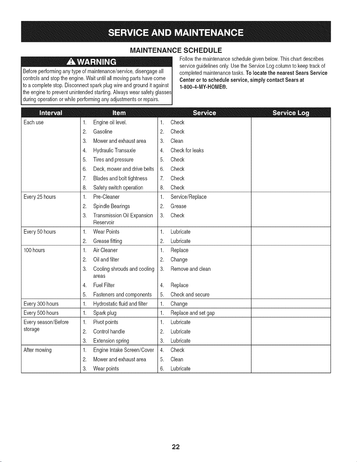
MAINTENANCE SCHEDULE
Beforeperformingany typeof maintenance/service,disengageall
controlsandstopthe engine.Waituntilall movingpartshavecome
to a completestop.Disconnectsparkplugwire andgroundit against
the engineto preventunintendedstarting.Alwayswearsafetyglasses
duringoperationorwhile performinganyadjustmentsor repairs.
Eachuse
Every25 hours
Every50 hours
100hours
Every300 hours
Every500 hours
Everyseason/Before
storage
Aftermowing
1. Engineoil level.
2. Gasoline
3. Mowerand exhaustarea
4. HydraulicTransaxle
5. Tiresand pressure
6. Deck,mowerand drivebelts
7. Bladesand bolttightness
8. Safetyswitchoperation
1. Pre-Cleaner
2. SpindleBearings
3. TransmissionOil Expansion
Reservoir
1. WearPoints
2. Greasefitting
1. Air Cleaner
2. Oil and filter
3. Coolingshroudsand cooling
areas
4. FuelFilter
5. Fastenersand components
1. Hydrostaticfluid and filter
1. Sparkplug
1. Pivotpoints
2. Controlhandle
3. Extensionspring
1. EngineIntakeScreen/Cover
2. Mowerand exhaustarea
3. Wearpoints
Followthe maintenanceschedulegivenbelow.Thischartdescribes
serviceguidelinesonly.Usethe ServiceLogcolumnto keeptrackof
completedmaintenancetasks.To locatethe nearest Sears Service
Centeror to scheduleservice,simplycontactSears at
1-800-4-MY-HOME®.
1. Check
2. Check
3. Clean
4. Checkfor leaks
5. Check
6. Check
7. Check
8. Check
1. Service/Replace
2. Grease
3. Check
1. Lubricate
2. Lubricate
1. Replace
2. Change
3. Removeandclean
4. Replace
5. Checkand secure
1. Change
1. Replaceand set gap
1. Lubricate
2. Lubricate
3. Lubricate
4. Check
5. Clean
6. Lubricate
22

OIL CHART
Applya fewdropsof SAEengineoil,grease,or usea spraylubricant.Applythe oil to bothsidesof pivotpoints.Wipeoff anyexcess.Startengine
andoperatemowerbrieflyto insurethatoil spreadsevenly.
Number of Oil Points Description
DALLY
4 DeckSuspensionPivots
4 HeightAdjustmentTurnbuckleClevisPin
2 HeightAdjustmentHandlePivots
2 HeightAdjustmentStopPivots
2 Deck LiftLinkagePivots
2 TransportHandlePivots
1 TransportHandlePin
2 Deck FrameUp-and-DownPivots
WEEKLY
1 SeatHinge
2 SteeringLeverLinkageRod EndBearings
2 LeverReturnAssemblyRodEndBearings
2 PumpControlLeverPivots
2 GrassCollectionSystemLid Hinges(If Moweris so equipped)
LUBRICATION CHART
Usea grease-gunfilledwith NO.2 MultipurposeLithiumBaseGrease
Numberof GreaseFittings Description
EVERY25 HOURS
3 BladeSpindleBearings
WEEKLY
2 FrontCasterWheels
2 FrontCasterWheelSpindles
2 MowerDeckBallWheels
Numberof Grease Points Description
WEEKLY
4 MowingDeckPivots
2 DeckTake-UpIdlerPivots
Hydrostatic Fluid: Rimula15W40recommended.
Spindle Lubricant:Useonly ShellAlvaniaRL2 grease. Thisgreaseisanamber-coloredgreasedesignedfor highspeedbearingapplications.
It hasa baseoil viscositythatreducesrunninglosses,hasbeenformulatedfor lownoise,has excellentcorrosionprotection,andhas excellent
bearinglubrication.
General Purpose Lubrication: Useany NLGIgrade2 multi-purposegrease. ShellAlbidaEP2is recommended.ShellAlbidaEP2 is a
red-coloredmulti-purposegreasedesignedfor heavy-dutybearingapplications.It hashighbaseoil viscosityfor mechanicalstability,has been
formulatedfor highload,low-speedapplications,andhas excellentlubricationandcorrosionprotection.
23
Beforeperforminganymaintenanceorrepairs,disengagethePTO,
movethedrivecontrolleversfullyoutwardintheneutralposition,
Iengagetheparkingbrake,stoptheengineandremovethekeyto
[preventunintendedstarting.
ENGINE MAINTENANCE
usedoil.
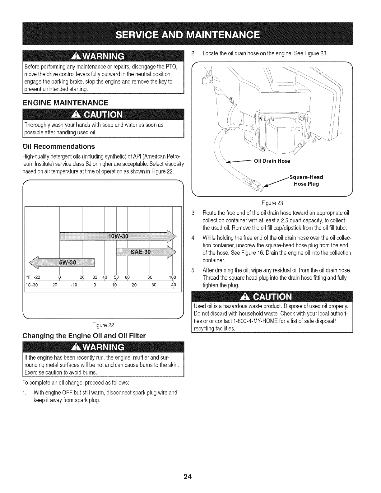
Oil Recommendations
High-qualitydetergentoils (includingsynthetic)of API(AmericanPetro-
leumInstitute)serviceclassSJ orhigherareacceptable.Selectviscosity
basedonairtemperatureat time ofoperationas shownin Figure22.
°F-20 0 210 312 410 510 610 810 100
°C -3_0 -2_0 -1_0 0 1_0 2_0 3_0 4_0
I I I I I I I I
J
Figure22
Changing the Engine Oil and Oil Filter
2. Locatethe oil drainhoseon the engine.SeeFigure23.
\
.
.
i,
/
Oil Drain Hose
._:_ j_Square=Heacl
HosePlug
Figure23
Routethe free endof the oildrainhosetowardanappropriateoil
collectioncontainerwithat leasta 2.5 quartcapacity,to collect
the usedoil. Removethe oilfill cap/dipstickfromthe oil fill tube.
Whileholdingthe free endof theoil drainhoseoverthe oilcollec-
tion container,unscrewthe square-headhoseplugfromthe end
of the hose.SeeFigure16.Drainthe engineoil intothe collection
container.
5. After drainingtheoil, wipe anyresidualoil from theoil drain hose.
Threadthe squareheadpluginto thedrainhosefitting andfully
tightenthe plug.
Usedoilis a hazardouswasteproduct.Disposeof usedoil properly.
Donot discardwithhouseholdwaste.Checkwithyourlocalauthori-
tiesor orcontact1-800-4-MY-HOMEfor a listof safedisposal/
recyclingfacilities.
If theenginehasbeenrecentlyrun,the engine,mufflerand sur-
roundingmetalsurfaceswill be hotandcan causeburnsto the skin.
Exercisecautionto avoidburns.
Tocompleteanoil change,proceedas follows:
1. Withengine OFF butstill warm,disconnectspark plugwire and
keepit awayfromsparkplug.
24
.
f
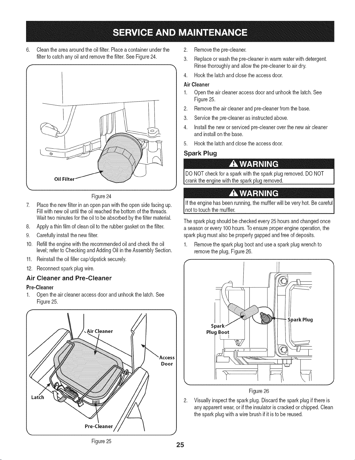
Cleantheareaaroundthe oilfilter. Placea containerunderthe
filterto catchanyoil andremovethe filter.SeeFigure24.
Oil Filter
Figure24
7. Placethe newfilter in an openpan with the open sidefacing up.
Fill withnewoil untilthe oil reachedthe bottomof the threads.
Waittwo minutesforthe oil to beabsorbedby the filtermaterial.
8. Applya thinfilm of clean oil to the rubbergasketon the filter.
9. Carefullyinstallthe newfilter.
10. Refillthe enginewiththe recommendedoil and checkthe oil
level;referto CheckingandAddingOilin theAssemblySection.
11. Reinstallthe oilfillercap/dipsticksecurely.
12. Reconnectsparkplugwire.
Air Cleaner and Pre=Cleaner
Pre-Cleaner
1. Openthe aircleaneraccessdoorandunhookthe latch.See
Figure25.
.Air Cleaner
2. Removethepre-cleaner.
3. Replaceor washthe pre-cleanerin warmwaterwithdetergent.
Rinsethoroughlyandallowthe pre-cleanerto airdry.
4. Hookthe latchandclosethe accessdoor.
Air Cleaner
1. Openthe air cleaneraccess doorand unhookthe latch.See
Figure25.
2. Removethe aircleanerandpre-cleanerfromthe base.
3. Servicethepre-cleaneras instructedabove.
4. Installthe newor servicedpre-cleaneroverthe newaircleaner
and installonthe base.
5. Hookthe latchandclosethe accessdoor.
Spark Plug
cranktheen( inewiththe s_ removed.
if the enginehas beenrunning,the mufflerwill beveryhot. Becareful
not to touchthemuffler.
The sparkplugshouldbecheckedevery25hoursandchangedonce
a seasonor every100hours.Toensureproperengineoperation,the
sparkplugmustalso beproperlygappedandfreeof deposits.
1. Removethe sparkplug bootand usea spark plugwrenchto
removethe plug,Figure26.
Figure26
Visuallyinspectthe sparkplug. Discardthe sparkplugif thereis
any apparentwear,or if the insulatoris crackedorchipped.Clean
the sparkplugwitha wire brushif it is to be reused.
Figure25
25
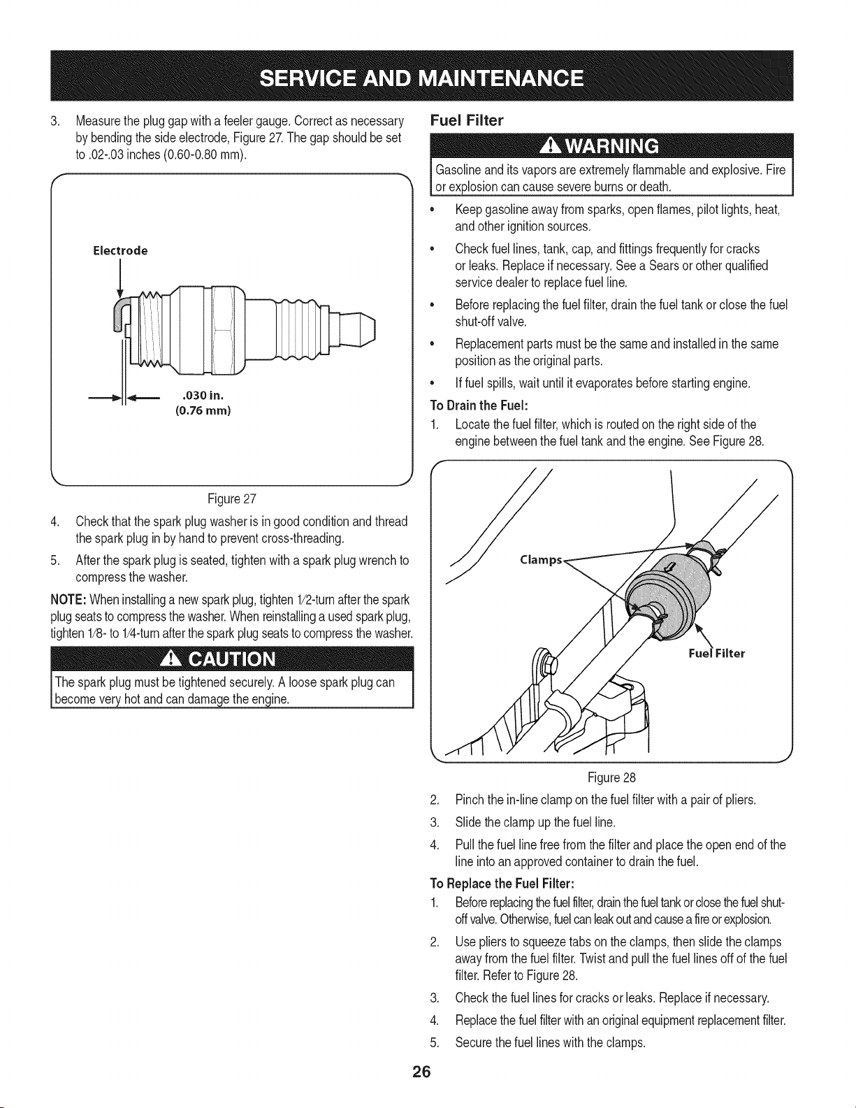
3. Measurethe plug gap with a feelergauge.Correctas necessary Fuel Filter
by bendingthe side electrode,Figure27.The gap shouldbe set
to .02-.03inches(0.60-0.80ram).
Electrode
Gasolineandits vaporsareextremelyflammableand explosive.Fire
or explosioncancausesevereburnsordeath.
• Keepgasolineawayfrom sparks,openflames,pilot lights,heat,
andother ignitionsources.
• Checkfuel lines,tank,cap,andfittingsfrequentlyfor cracks
or leaks.Replaceif necessary.Seea Searsor otherqualified
servicedealerto replacefuel line.
• Beforereplacingthe fuelfilter,drainthe fuel tankor close the fuel
shut-offvalve.
• Replacementpartsmust be the sameand installedin the same
positionas the originalparts.
• If fuel spills,wait untilit evaporatesbeforestartingengine.
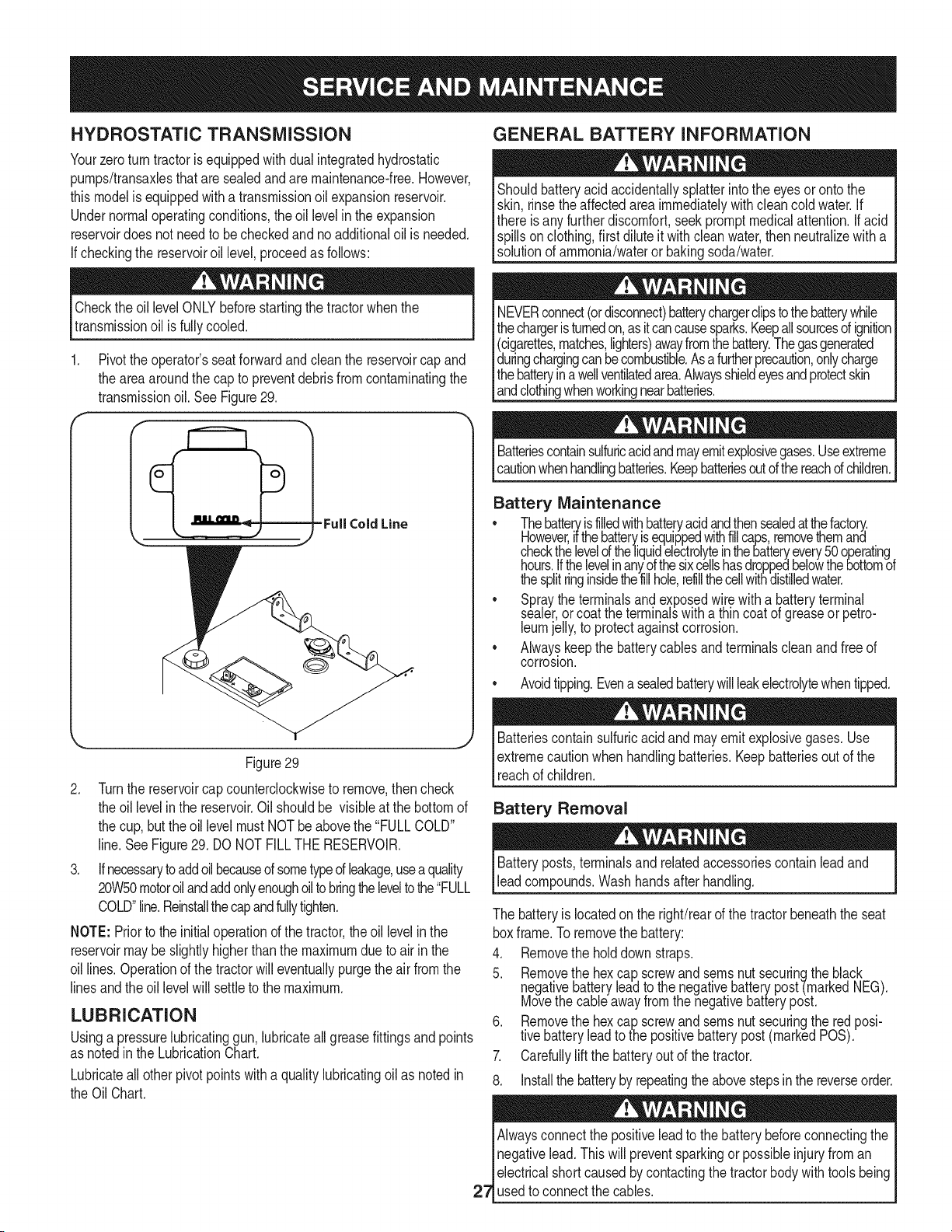
To Drainthe Fuel:
1. Locatethe fuel filter,which is routedon the right sideof the
enginebetweenthe fueltankandthe engine.See Figure28.
Figure27
4. Checkthat thespark plug washeris in good conditionand thread
the sparkplugin by handto preventcross-threading.
5. Afterthe sparkplug is seated,tightenwith a spark plugwrenchto
compressthe washer.
NOTE:Wheninstallinga newsparkplug,tighten1/2-turnafterthe spark
plugseatsto compressthe washer.Whenreinstallinga usedsparkplug,
tighten1/8-to 1/4-turnafterthe sparkplugseatsto compressthe washer.
Thesparkplugmustbetightenedsecurely.A loosesparkplugcan
becomeveryhotandcan damagethe engine.
J
Figure28
2. Pinchthe in-lineclamp onthe fuel filterwitha pairof pliers.
3. Slide the clampup thefuel line.
4. Pullthe fuel linefreefromthe filterand placetheopenendof the
line intoanapprovedcontainerto drainthe fuel.
To Replacethe Fuel Filter:
1. Beforereplacingthefuelfilter,drainthefueltankor closethefuelshut-
offvalve.Otherwise,fuelcanleakoutandcausea fireorexplosion.
2. Usepliersto squeezetabsonthe clamps,thenslidethe clamps
awayfromthe fuel filter.Twistandpullthe fuel linesoffof the fuel
filter.Referto Figure28.
3. Checkthe fuel linesforcracks or leaks.Replaceif necessary.
4. Replacethe fuelfilterwithan originalequipmentreplacementfilter.
5. Securethefuel lineswith the clamps.
26
HYDROSTATIC TRANSMiSSiON
Yourzeroturntractoris equippedwithdualintegratedhydrostatic
pumps/transaxlesthataresealedandaremaintenance-free.However,
thismodelis equippedwitha transmissionoil expansionreservoir.
Undernormaloperatingconditions,the oillevelin the expansion
reservoirdoes not needto becheckedand noadditionaloil is needed.
If checkingthe reservoiroil level,proceedas follows:
Checkthe oil levelONLYbeforestartingthe tractorwhen the
transmissionoil is fullycooled.
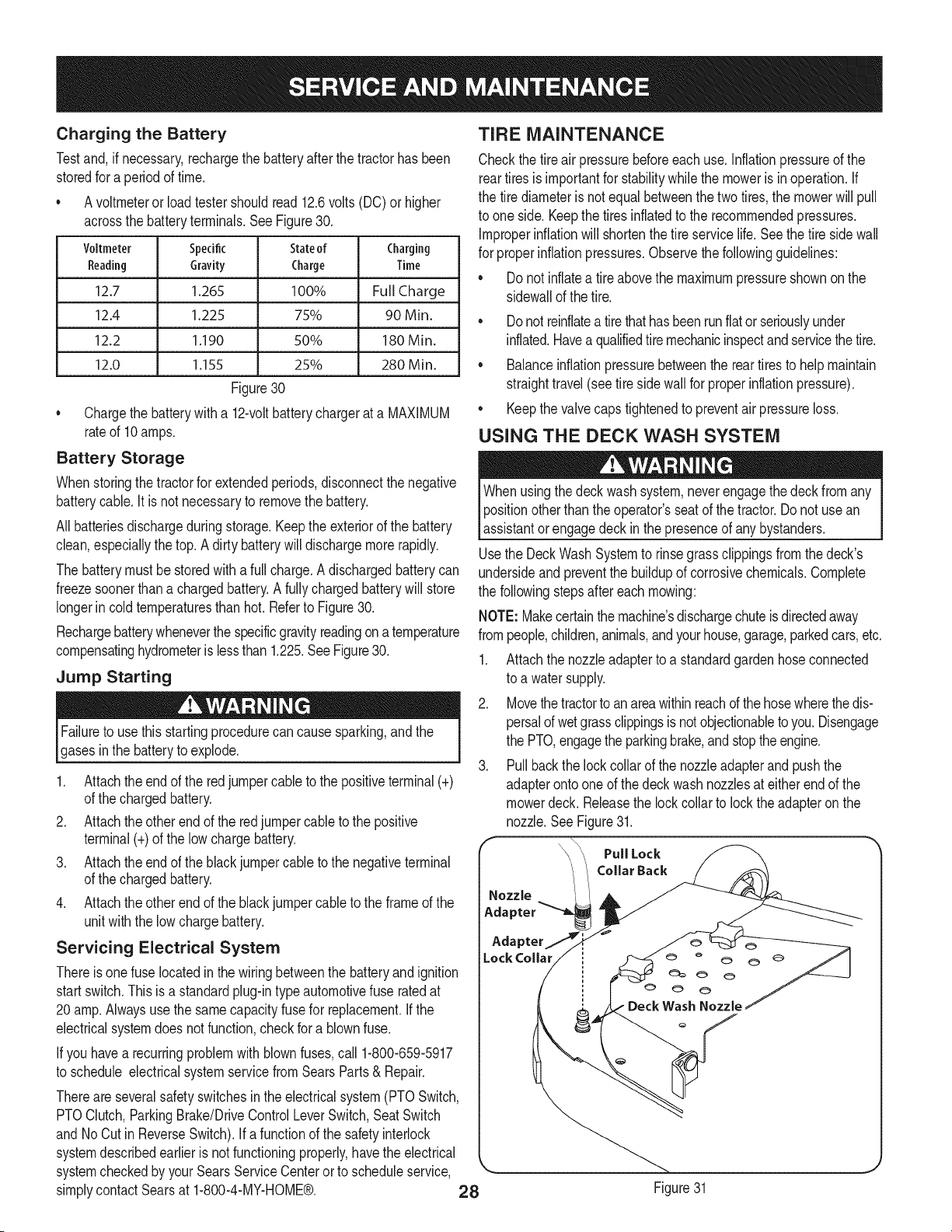
1. Pivotthe operator'sseatforwardandclean the reservoircapand
the areaaroundthe cap to preventdebrisfromcontaminatingthe
transmissionoil. SeeFigure29.
-Full Cold Line
k,_ [ j
Figure29
2. Turnthe reservoircapcounterclockwiseto remove,thencheck
the oillevelin the reservoir.Oil shouldbe visibleat the bottomof
the cup,butthe oillevel mustNOTbe abovethe "FULLCOLD"
line.SeeFigure29. DONOTFILLTHERESERVOIR.
3. If necessarytoaddoil becaused sometypeof leakage,useaquality
20W50motoroilandaddonlyenoughoiltobringtheleveltothe"FULL
COLD"line.Reinstallthecapandfullytighten.
NOTE: Priorto the initialoperationd the tractor,the oil levelin the
reservoirmaybe slightlyhigherthan the maximumdueto airin the
oil lines.Operationof thetractorwill eventuallypurgethe air fromthe
linesandthe oil levelwill settleto the maximum.
LUBRICATION
Usinga pressurelubricatinggun, lubricateall greasefittingsandpoints
as notedinthe LubricationChart.
Lubricateall otherpivotpointswithaqualitylubricatingoil as notedin
the OilChart.
GENERAL BATTERY INFORMATION
Shouldbatteryacid accidentallysplatterintothe eyesor ontothe
skin, rinsetheaffectedareaimmediatelywithcleancold water.If
there isany furtherdiscomfort,seekpromptmedicalattention.Ifacid
spillsonclothing,first diluteit withcleanwater,thenneutralizewitha
solutionof ammonia/wateror bakingsoda/water.
NEVERconnect(ordisconnect)batterychargerclipstothebatterywhile
thechargeristurnedon,as itcancausesparks.Keepallsourcesof ignition
(cigarettes,matches,lighters)awayfromthebattery.Thegasgenerated
duringchargingcanbecombustible.Asafurtherprecaution,onlycharge
thebatteryinawellventilatedarea.Alwaysshieldeyesandprotectskin
[andc othngwhenworkngnearbatteries.
Batteriescontainsulfuricacidandmayemitexplosivegases.Useextreme
cautionwhenhandlingbatteries.Keepbatteriesoutofthereachofchildren.
Battery Maintenance
• Thebatte_isfilledwithbatteryacidandthensealedatthefactory.
However,ifthebatteryisequippedwithfillcaps,removethemant
checkthelevelof the]iquidelectroly!einthebatteryevery50operating.
hours.Ifthelevelinanyofthesixcellshasdroppetbelowthebottomot
thesplitringinsidethefillhole,refillthecellwithdistilledwater.
• Spraythe terminalsand exposedwirewith a b.atteryterminal
sealer,orcoatthe terminalswitha thincoatot greaseorpetro-
leumjelly,to protectagainstcorrosion.
• Alwayskeepthe batterycablesand terminalscleanand free of
corrosion.
• Avoidtipping.Evenasealedbatterywillleakelectrolytewhentipped.
Batteriescontainsulfuricacidandmayemitexplosivegases. Use
extremecautionwhen handlingbatteries.Keepbatteriesoutof the
reachof children.
Battery Removal
Batteryposts,terminalsand relatedaccessoriescontainleadand
leadcompounds.Wash handsafter handling.
The batteryis locatedonthe right/rearof the tractorbeneaththe seat
boxframe.To removethe battery:
4. Removethe holddownstraps.
5. Remove!he hexcap screwandseresnut securingthe black
negativebatteryleadto the negativebatterypost-(markedNEG).
Movethe cableawayfromthe negativebatterypost.
6. Removethe hexcap screwandsernsnut securingthe redposi-
tivebatteryleadto the positivebatterypost(markedPOS).
7. Carefullylift the batteryout of the tractor.
8. Installthe batteryby repeatingtheabovestepsinthe reverseorder.
Alwaysconnectthe positiveleadto the batterybeforeconnectingthe
Inegativelead.Thiswill preventsparkingorpossibleinjuryfroman
| electricalshortcaused bycontactingthe tractorbodywith tools being
27_usedto connectthe cables.
Charging the Battery
Testand,ifnecessary,rechargethebatteryafterthetractorhasbeen
storedforaperiodoftime.
• Avoltmeteror loadtestershouldread12.6volts(DC)or higher
acrossthe batteryterminals.SeeFigure30.
Voltmeter Specific Charging
Reading Gravity Time
12.7 1.265 Full Charge
12.4 1.225 90 Min.
12.2 1.190 180 Min.
12.0 1.155 280 Min.
Stateof
Charge
100%
75%
50%
25%
Figure30
* Chargethe batterywith a 12-voltbatterychargerat a MAXIMUM
rateof 10amps.
Battery Storage
Whenstoringthetractorfor extendedperiods,disconnectthe negative
batterycable.It is not necessaryto removethe battery.
All batteriesdischargeduringstorage.Keepthe exteriorof the battery
clean,especiallythe top.Adirty batterywill dischargemorerapidly.
The batterymustbe storedwitha full charge.A dischargedbatterycan
freezesoonerthan a chargedbattery.A fullychargedbatterywill store
longerin coldtemperaturesthan hot. Referto Figure30.
Rechargebatterywheneverthespecificgravityreadingona temperature
compensatinghydrometeris lessthan 1.225.SeeFigure30.
Jump Starting
Failureto use thisstartingprocedurecan causesparking,andthe
gasesinthe batteryto explode.
1. Attachtheend of the redjumpercableto the positiveterminal(+)
of the chargedbattery.
2. Attachtheotherend of the redjumpercableto the positive
terminal(+)of the lowchargebattery.
3. Attachtheend of theblack jumpercable to the negativeterminal
of the chargedbattery.
4. Attachtheotherend of the blackjumper cableto the frameof the
unitwiththe low chargebattery.
Servicing Electrical System
Thereis onefuselocatedinthe wiringbetweenthe batteryandignition
startswitch.Thisis a standardplug-intypeautomotivefuse ratedat
20amp.Alwaysusethe samecapacityfusefor replacement.Ifthe
electricalsystemdoes notfunction,checkfor a blownfuse.
Ifyou havea recurringproblemwithblownfuses,call 1-800-659-5917
to schedule electricalsystemservicefromSearsParts& Repair.
Thereareseveralsafetyswitchesinthe electricalsystem(PTOSwitch,
PTOClutch,ParkingBrake/DriveControlLeverSwitch,SeatSwitch
andNo Cutin ReverseSwitch).Ifa functionof the safetyinterlock
systemdescribedearlieris not functioningproperly,havethe electrical
systemcheckedby yourSearsServiceCenterorto scheduleservice,
simplycontactSearsat 1-800-4-MY-HOME®. 28
TIRE MAINTENANCE
Checkthe tireair pressurebeforeeachuse.Inflationpressureof the
reartiresis importantfor stabilitywhilethe moweris in operation.If
the tire diameteris notequalbetweenthe twotires,the mowerwill pull
to one side.Keepthe tiresinflatedto the recommendedpressures.
Improperinflationwill shortenthe tire servicelife.Seethe tire sidewall
for properinflationpressures.Observethe followingguidelines:
• Donot inflatea tireabovethe maximumpressureshownonthe
sidewallof the tire.
• Donot reinflatea tire thathasbeen runflat or seriouslyunder
inflated.Havea qualifiedtiremechanicinspectand servicethe tire.
• Balanceinflationpressurebetweenthe rear tires to helpmaintain
straighttravel(seetire sidewall for properinflationpressure).
• Keepthevalve caps tightenedto preventair pressureloss.
USING THE DECK WASH SYSTEM
Whenusingthe deckwashsystem,neverengagethe deckfromany
positionotherthan theoperator'sseatof the tractor.Donot usean
assistantor engagedeckinthe presenceof anybystanders.
Usethe DeckWashSystemto rinsegrassclippingsfromthe deck's
undersideandpreventthe buildupof corrosivechemicals.Complete
the followingstepsaftereach mowing:
NOTE: Makecertainthemachine'sdischargechuteis directedaway
frompeople,children,animals,andyourhouse,garage,parkedcars,etc.
1. Attachthe nozzleadapterto a standardgardenhoseconnected
to a watersupply.
2. Movethetractorto anareawithinreachof the hosewherethe dis-
persalof wetgrassclippingsis notobjectionabletoyou.Disengage
the PTO,engagethe parkingbrake,andstoptheengine.
3. Pullbackthe lockcollarof the nozzleadapterand pushthe
adapteronto oneof the deckwashnozzlesat eitherendof the
mowerdeck. Releasethe lockcollarto lockthe adapteronthe
nozzle.SeeFigure31.
Pull Lock
Collar Back
Adapter
Lock Collar
Figure31
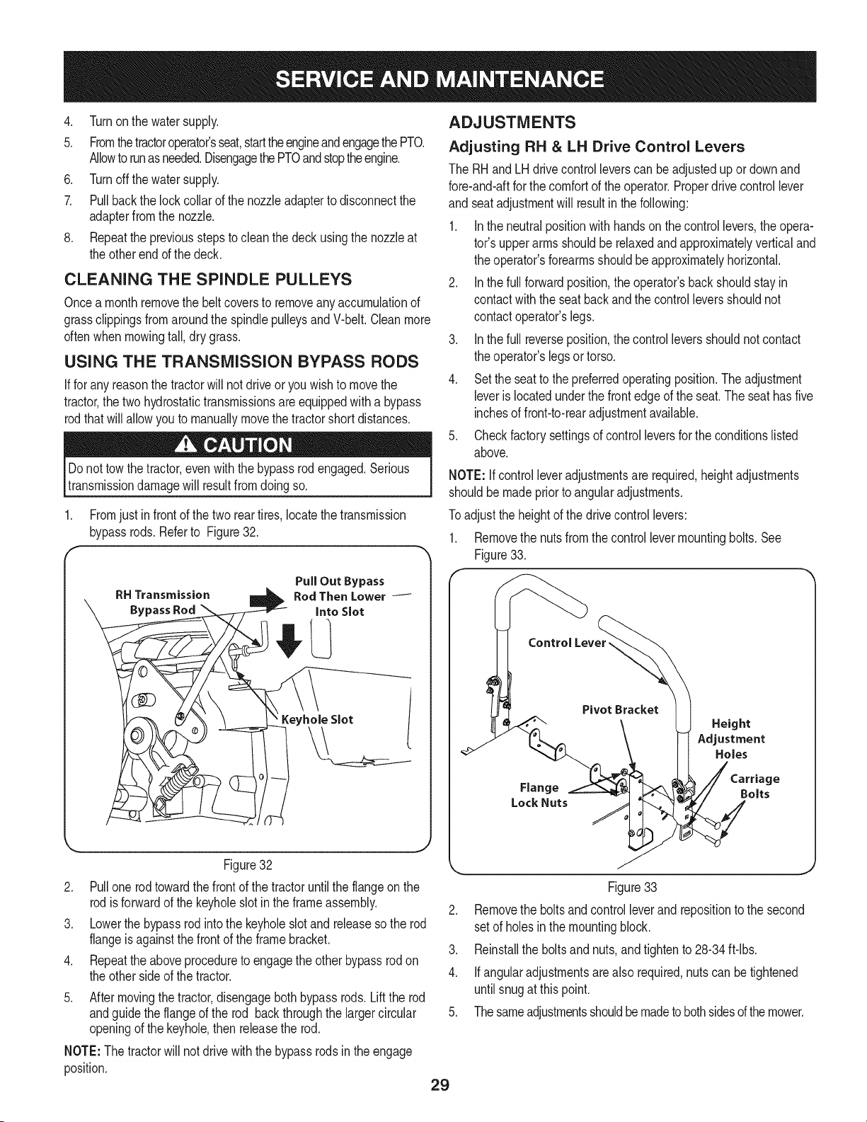
4. Turnonthewatersupply.
5. Fromthetractoroperator'sseat,starttheengineandengagethePTO.
Allowtorunasneeded.DisengagethePTOandstoptheengine.
6. Turnoffthewatersupply.
7. Pullbackthelockcollarofthenozzleadaptertodisconnectthe
adapterfromthenozzle.
8. Repeatthepreviousstepstocleanthedeckusingthenozzleat
theotherendofthedeck.
CLEANING THE SPINDLE PULLEYS
Oncea monthremovethe beltcoversto removeanyaccumulationof
grassclippingsfromaroundthe spindlepulleysandV-belt.Cleanmore
oftenwhenmowingtall,dry grass.
USING THE TRANSMISSION BYPASS RODS
If forany reasonthe tractorwill notdriveor youwishto movethe
tractor,the two hydrostatictransmissionsareequippedwitha bypass
rodthatwill allowyouto manuallymovethetractorshortdistances.
Do nottowthe tractor,evenwith thebypassrodengaged.Serious
transmissiondamagewill resultfromdoingso.
1. Fromjustin frontof the tworeartires, locatethe transmission
bypassrods.Referto Figure32.
f
Figure32
2. Pull one rod towardthe frontof the tractoruntilthe flangeon the
rodis forwardof the keyholeslotinthe frameassembly.
3. Lowerthe bypassrod intothe keyholeslot and releaseso the rod
flangeis againstthefrontof the framebracket.
4. Repeattheaboveprocedureto engagethe other bypassrod on
the othersideof the tractor.
5. After movingthe tractor,disengageboth bypassrods. Lift the rod
andguidethe flangeof the rod backthroughthe largercircular
openingof the keyhole,then releasethe rod.
NOTE:The tractorwill not drivewiththe bypassrods inthe engage
position.
ADJUSTMENTS
Adjusting RH & LH Drive Control Levers
The RHandLH drivecontrolleverscan beadjustedupor downand
fore-and-aftforthe comfortof the operator.Properdrivecontrollever
and seatadjustmentwill resultinthefollowing:
1. Inthe neutralpositionwith handson the controllevers,the opera-
tot's upperarmsshouldbe relaxedand approximatelyverticaland
the operator'sforearmsshouldbe approximatelyhorizontal.
2. Inthe full forwardposition,the operator'sbackshouldstayin
contactwiththe seatbackandthe controlleversshouldnot
contactoperator'slegs.
3. Inthe full reverseposition,thecontrolleversshouldnotcontact
the operator'slegsor torso.
4. Setthe seatto thepreferredoperatingposition.Theadjustment
leveris locatedunderthe frontedgeof the seat.The seathasfive
inchesof front-to-rearadjustmentavailable.
5. Checkfactorysettingsof controlleversforthe conditionslisted
above.
NOTE:If controlleveradjustmentsare required,heightadjustments
shouldbe madepriorto angularadjustments.
Toadjustthe heightof the drivecontrollevers:
1. Removethe nuts fromthe control levermountingbolts.See
Figure33.
Control Lever,
Pivot Bracket
Height
Adjustment
Holes
Flange Bolts
Lock Nuts
Figure33
2. Removethe boltsandcontrolleverandrepositionto the second
setof holesinthe mountingblock.
3. Reinstallthe boltsandnuts,andtightento 28-34ft-lbs.
4. Ifangularadjustmentsarealso required,nutscan betightened
untilsnugat thispoint.
5. Thesameadjustmentsshouldbe madeto bothsidesof themower.
29
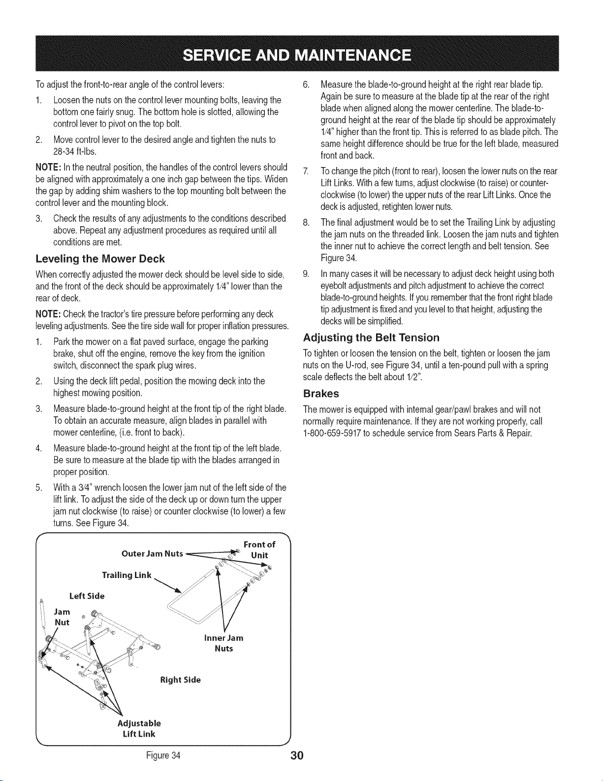
Toadjustthe front-to-rearangleof the controllevers:
1. Loosenthe nuts on the controllevermountingbolts, leavingthe
bottomonefairlysnug.Thebottomholeis slotted,allowingthe
controlleverto pivoton the top bolt.
2. Movecontrolleverto the desiredangle and tightenthe nuts to
28-34ft-lbs.
NOTE: Inthe neutralposition,the handlesof the controlleversshould
bealignedwithapproximatelya oneinchgap betweenthe tips.Widen
thegap by addingshimwashersto the top mountingbolt betweenthe
controlleverandthe mountingblock.
3. Checkthe resultsof anyadjustmentsto the conditionsdescribed
above.Repeatany adjustmentproceduresas requireduntilall
conditionsaremet.
Leveling the Mower Deck
Whencorrectlyadjustedthe mowerdeckshouldbe levelsideto side,
andthe frontof the deckshouldbeapproximately1/4"lowerthan the
rearof deck.
NOTE:Checkthetractor'stirepressurebeforeperforminganydeck
levelingadjustments.Seethe tiresidewallforproperinflationpressures.
1. Parkthe moweron a flat pavedsurface,engagethe parking
brake,shutoff the engine,removethe keyfromthe ignition
switch,disconnectthe sparkplugwires.
2. Usingthe deck lift pedal,positionthe mowingdeck intothe
highestmowingposition.
3. Measureblade-to-groundheightat the front tip of the rightblade.
Toobtainanaccuratemeasure,alignbladesin parallelwith
mowercenterline,(i.e.frontto back).
4. Measureblade-to-groundheightat the front tip of the left blade.
Besureto measureat the bladetip withthe bladesarrangedin
properposition.
5. Witha 3/4" wrenchloosenthe lowerjam nutof the leftside of the
lift link.Toadjustthe sideof the deckup ordownturn the upper
jam nutclockwise(to raise)or counterclockwise(to lower)a few
turns.SeeFigure34.
Front of
Outer Jam Nuts Unit
.
Measurethe blade-to-groundheightat the rightrearbladetip.
Againbesureto measureat the bladetip at the rearof the right
bladewhenalignedalongthe mowercenterline.The blade-to-
groundheightat the rearof the bladetip shouldbeapproximately
1/4"higherthanthe fronttip.Thisis referredto as bladepitch.The
sameheightdifferenceshouldbe truefor the leftblade,measured
frontandback.
7. Tochangethepitch (frontto rear),loosenthe lowernuts on the rear
LiftLinks.Withafewturns,adjustclockwise(to raise)orcounter-
clockwise(tolower)theuppernutsof the rearLiftLinks.Oncethe
deckis adjusted,retightenlowernuts.
8. The finaladjustmentwouldbe to set the TrailingLink byadjusting
the jam nutson the threadedlink.Loosenthejam nutsandtighten
the innernutto achievethe correctlengthand belttension.See
Figure34.
9. Inmanycasesit will benecessaryto adjustdeckheightusingboth
eyeboltadjustmentsandpitchadjustmentto achievethecorrect
blade-to-groundheights.If yourememberthatthefront rightblade
tip adjustmentisfixedandyouleveltothatheight,adjustingthe
deckswillbesimplified.
Adjusting the Belt Tension
Totightenorloosenthe tensiononthe belt,tightenorloosenthejam
nutson the U-rod,see Figure34, untila ten-poundpullwitha spring
scaledeflectsthe beltabout 1/2".
Brakes
The moweris equippedwith internalgear/pawlbrakesandwill not
normallyrequiremaintenance.If they are not workingproperly,call
1-800-659-5917to scheduleservicefromSearsParts& Repair.
Trailing Link
Left Side
Jam
Nut
Inner Jam
Nuts
Right Side
Adjustable
Lift Link
Figure34 30
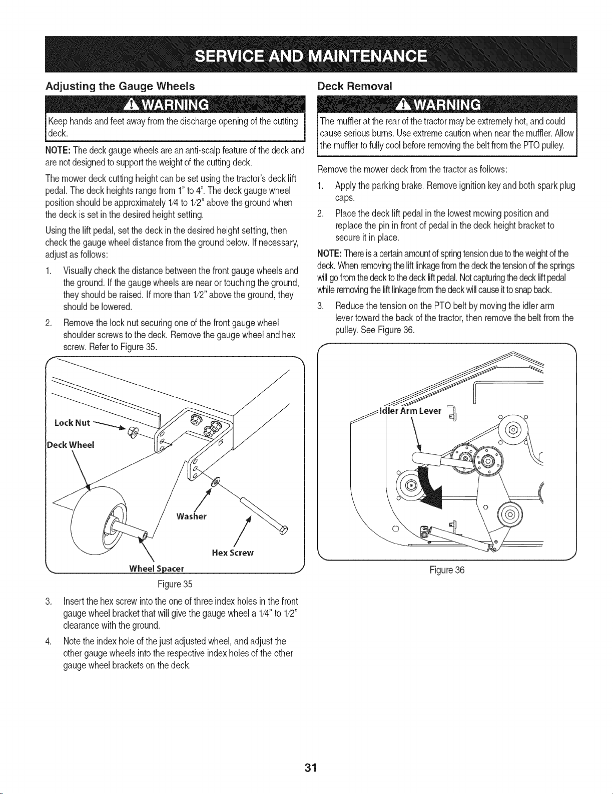
Adjusting the Gauge Wheels
Keephandsandfeetawayfromthe dischargeopeningof thecutting
deck.
NOTE:The deckgaugewheelsareananti-scalpfeatureof thedeckand
arenotdesignedto supporttheweightof thecuttingdeck.
Themowerdeckcuttingheightcanbe setusingthe tractor'sdecklift
pedal.Thedeckheightsrangefrom 1"to 4".Thedeckgaugewheel
positionshouldbe approximately1/4to 1/2"abovethe groundwhen
the deckis setinthe desiredheightsetting.
Usingthe lift pedal,setthedeck inthe desiredheightsetting,then
checkthe gaugewheeldistancefromthe groundbelow.Ifnecessary,
adjustas follows:
1. Visuallycheckthedistancebetweenthe frontgaugewheelsand
the ground.If thegaugewheelsarenearortouchingtheground,
theyshouldberaised.If morethan 1/2"abovethe ground,they
shouldbelowered.
.
Removethelocknut securingoneof the frontgaugewheel
shoulderscrewsto the deck.Removethegaugewheeland hex
screw.Referto Figure35.
/
Washer
Wheel S _acer
Figure35
/
Hex Screw
3. Insertthe hexscrewintothe one of three indexholesin the front
gaugewheelbracketthatwill givethe gaugewheela 1/4"to 1/2"
clearancewiththe ground.
4. Notethe indexhole of thejust adjustedwheel,and adjustthe
othergaugewheelsinto the respectiveindexholesof the other
gaugewheelbracketson thedeck.
Deck Removal
The mufflerat the rearofthe tractormaybeextremelyhot,andcould I
Icauseseriousburns.Useextremecautionwhennearthe muffler.AllowI
_themufflertofullycoolbeforeremovingthebeltfrom thePTOpulley. J
Removethe mowerdeckfromthe tractoras follows:
1. Applythe parkingbrake.Removeignitionkeyandbothsparkplug
caps.
2. Placethe deck lift pedalin the lowestmowingpositionand
replacethe pinin frontof pedalin thedeckheightbracketto
secureit in place.
NOTE:Thereisacertainamountof springtensionduetotheweightof the
deck.Whenremovingtheliftlinkagefromthedeckthetensiond thesprings
willgofromthedeckto thedeckliftpedal.Notcapturingthedeckliftpedal
whileremovingtheliftlinkagefromthedeckwillcauseitto snapback.
3. Reducethe tensiononthe PTObelt by movingthe idlerarm
levertowardthe backof thetractor,then removethe beltfromthe
pulley.SeeFigure36.
ArmLever =_]
\
Figure36
31
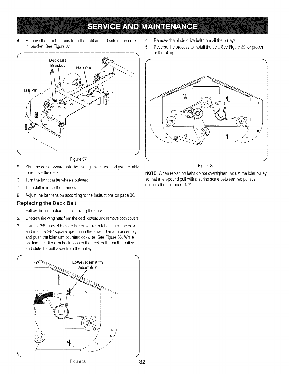
4. Removethe four hair pinsfrom the rightand left sideof the deck 4.
lift bracket.See Figure37. 5.
Deck Lift
Bracket
Hair Pin
Hair Pin
Figure37
5. Shift the deckforward untilthe trailinglinkisfree and youare able
to removethe deck.
6. Turnthe front casterwheelsoutward.
7. Toinstallreversethe process.
8. Adjustthe belttensionaccordingto the instructionson page 30.
Replacing the Deck Belt
1. Followthe instructionsfor removingthedeck.
2. Unscrewthewingnutsfromthedeckcoversand removebothcovers.
3. Usinga 3/8" socketbreakerbaror socketratchetinsertthedrive
endintothe 3/8" squareopeningin the loweridlerarm assembly
andpushthe idlerarmcounterclockwise.SeeFigure38.While
holdingthe idlerarm back,loosenthedeck beltfromthe pulley
andslidethe belt awayfromthe pulley.
LoweridlerArm
Assembly
Removethe bladedrive beltfromallthe pulleys.
Reversethe processto installthe belt.SeeFigure39 for proper
belt routing.
Figure39
NOTE: Whenreplacingbeltsdo notovertighten.Adjustthe idlerpulley
so thata ten-poundpullwitha springscalebetweentwopulleys
deflectsthe belt about1/2".
Figure38 32
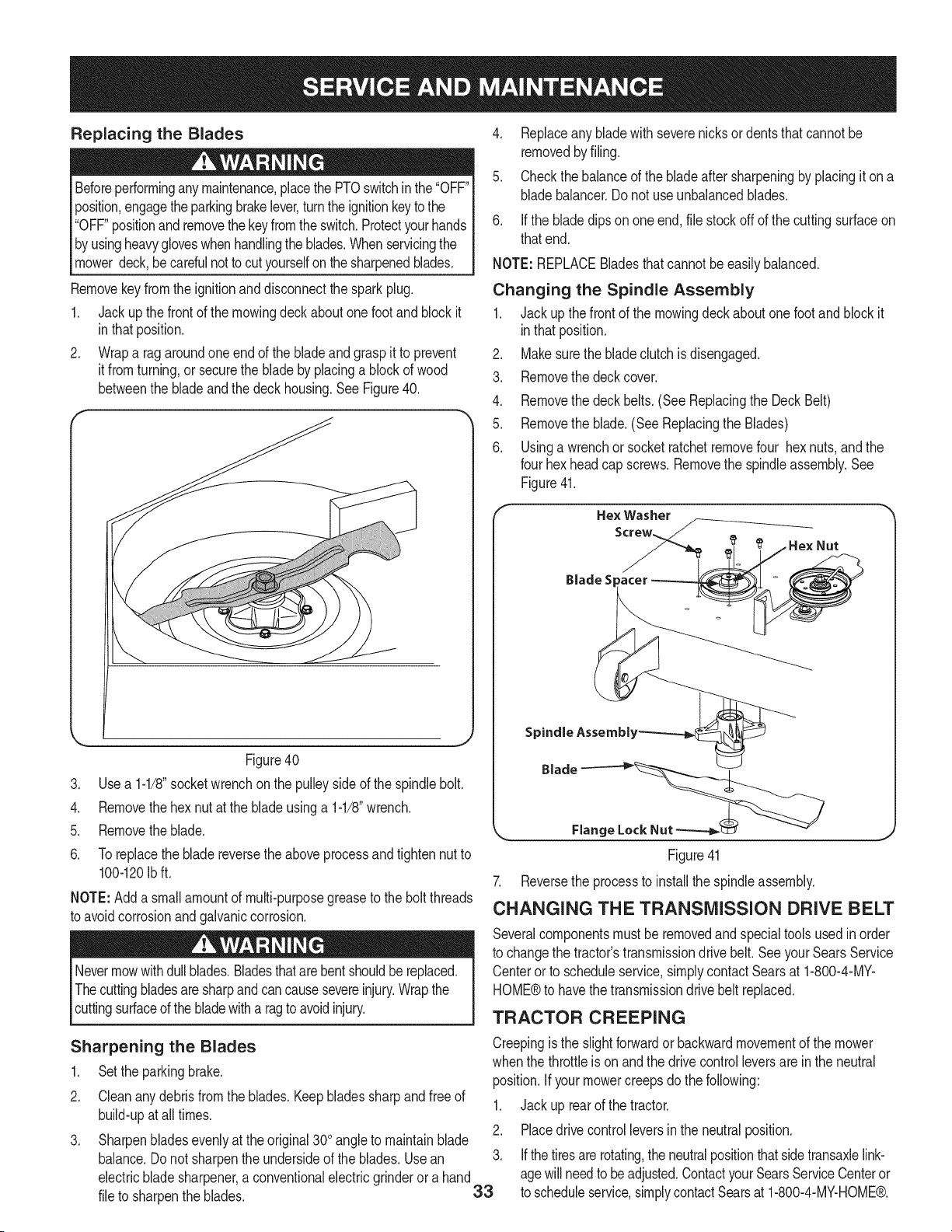
Replacing the Blades
Beforeperforminganymaintenance,placethePTOswitchinthe "OFF"
position,engagethe parkingbrakelever,turnthe ignitionkeyto the
"OFF"positionand removethe keyfromthe switch.Protectyourhands
by usingheavygloveswhenhandlingthe blades.Whenservicingthe
mowerdeck,becarefulnot tocutyourselfon thesharpenedblades.
Removekeyfromthe ignitionanddisconnectthe sparkplug.
1. Jackup thefrontof the mowingdeckaboutone footand blockit
in thatposition.
2. Wrapa rag aroundone end of the bladeand graspit to prevent
it fromturning,or securethe bladeby placinga blockof wood
betweenthe bladeandthedeck housing.SeeFigure40.
Figure40
3. Use a 1-1/8"socketwrenchon the pulleysideof the spindlebolt.
4. Removethehex nutat the bladeusinga 1-1/8"wrench.
5. Removetheblade.
6. Toreplacethe blade reversethe aboveprocessand tightennut to
100-120Ibft.
NOTE:Adda smallamountof multi-purposegreaseto the boltthreads
to avoidcorrosionandgalvaniccorrosion.
Nevermowwithdullblades.Bladesthatarebentshouldbereplaced.
Thecuttingbladesaresharpandcancausesevereinjury.Wrapthe
cuttingsurfaceof the bladewitha ragtoavoidinjury.
Sharpening the Blades
1. Setthe parkingbrake.
2. Cleananydebrisfrom the blades.Keepbladessharpand freeof
build-upat alltimes.
3. Sharpenbladesevenlyat the original300angleto maintainblade
balance.Donot sharpenthe undersideof the blades.Usean
electricbladesharpener,a conventionalelectricgrinderora hand
file to sharpenthe blades.
,
33
4. Replaceany bladewithseverenicksordentsthatcannotbe
removedbyfiling.
5. Checkthe balanceof the bladeafter sharpeningby placingit on a
bladebalancer.Do not useunbalancedblades.
6. Ifthe bladedipsononeend, file stockoff of the cuttingsurfaceon
thatend.
NOTE:REPLACEBladesthatcannotbeeasilybalanced.
Changing the Spindle Assembly
1. Jack upthe frontof the mowingdeckaboutonefootandblockit
inthatposition.
2. Makesurethe bladeclutchis disengaged.
3. Removethe deckcover.
4. Removethe deckbelts.(SeeReplacingthe DeckBelt)
5. Removethe blade.(SeeReplacingthe Blades)
6. Usinga wrenchor socketratchetremovefour hexnuts,andthe
four hexheadcapscrews.Removethe spindleassembly.See
Figure41.
Hex Washer
BladeS
Spindle Assembl_
Blade
Flang
Figure41
7. Reversethe processto install the spindleassembly.
CHANGING THE TRANSMISSION DRIVE BELT
Severalcomponentsmustbe removedand specialtoolsusedinorder
to changethe tractor'stransmissiondrivebelt.SeeyourSearsService
Centeror to scheduleservice,simplycontactSearsat 1-800-4-MY-
HOME®to havethe transmissiondrivebelt replaced.
TRACTOR CREEPING
Creepingis the slightforwardorbackwardmovementof the mower
whenthe throttleis on andthe drive controlleversareinthe neutral
position.Ifyour mowercreepsdo the following:
1. Jack up rearof the tractor.
2. Placedrivecontrolleversinthe neutralposition.
Ifthetiresarerotating,the neutralpositionthatsidetransaxlelink-
agewillneedto beadjusted.ContactyourSearsServiceCenteror
to scheduleservice,simplycontactSearsat 1-800-4-MY-HOME®.
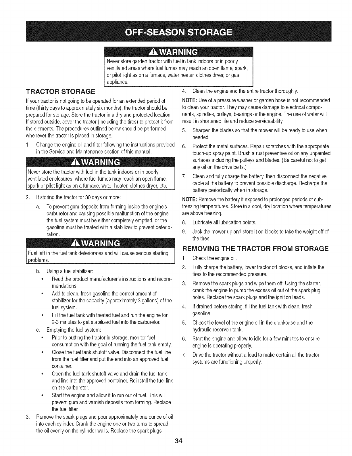
TRACTOR STORAGE
If yourtractoris notgoingto be operatedfor an extendedperiodof
time(thirtydaysto approximatelysix months),the tractorshouldbe
preparedfor storage.Storethetractorin a dry andprotectedlocation.
If storedoutside,coverthe tractor(includingthe tires)to protectit from
the elements.Theproceduresoutlinedbelowshouldbeperformed
wheneverthetractoris placedin storage.
1. Changethe engineoil and filterfollowingthe instructionsprovided
in theServiceand Maintenancesectionof thismanual..
Neverstorethe tractorwithfuel inthe tankindoorsor in poorly
ventilatedenclosures,wherefuelfumesmayreachan openflame,
sparkor pilotlight as ona furnace,waterheater,clothesdryer,etc.
.
Neverstoregardentractorwithfuel intankindoorsor in poorly
ventilatedareaswherefuel fumesmayreachan openflame,spark,
or pilot lightas ona furnace,waterheater,clothesdryer,or gas
appliance.
4. Cleanthe engineand the entiretractorthoroughly.
NOTE:Useof a pressurewasherorgardenhoseis not recommended
to clean yourtractor.Theymaycausedamageto electricalcompo-
nents,spindles,pulleys,bearingsor theengine.The useof waterwill
resultin shortenedlifeand reduceserviceability.
5. Sharpenthe bladesso thatthe mowerwill be readyto use when
needed.
If storingthetractorfor 30daysor more:
a. Topreventgum depositsfrom forminginsidetheengine's
carburetorand causingpossiblemalfunctiond the engine,
the fuelsystemmust beeithercompletelyemptied,orthe
gasolinemustbetreatedwitha stabilizerto preventdeterio-
ration.
6. Protectthe metalsurfaces.Repairscratcheswiththe appropriate
touch-upspraypaint.Brusha rustpreventiveoilonany unpainted
surfacesincludingthe pulleysandblades.(Becarefulnot to get
any oilon thedrive belts.)
7. Cleanand fully chargethe battery,thendisconnectthe negative
cableat thebatteryto preventpossibledischarge.Rechargethe
batteryperiodicallywhenin storage.
NOTE:Removethebatteryif exposedto prolongedperiodsof sub-
freezingtemperatures.Storeina cool,dry locationwheretemperatures
areabovefreezing.
8. Lubricatealllubricationpoints.
9. Jack the mowerup and storeit on blocksto take the weightoff of
the tires.
9roblems.
.
b. Usingafuel stabilizer:
• Readthe productmanufacturer'sinstructionsand recom-
mendations.
• Addto clean,freshgasolinethe correctamountof
stabilizerforthe capacity(approximately3 gallons)of the
fuel system.
• Fillthe fuel tankwithtreatedfueland runthe enginefor
2-3minutesto get stabilizedfuel intothe carburetor.
c. Emptyingthefuel system:
• Priorto puttingthe tractorinstorage,monitorfuel
consumptionwith the goalof runningthefuel tank empty.
• Closethe fuel tankshutoffvalve.Disconnectthe fuel line
fromthe fuel filterandput theend intoanapprovedfuel
container.
• Openthe fuel tankshutoffvalveanddrainthefuel tank
andlineintothe approvedcontainer.Reinstallthe fuelline
onthe carburetor.
• Startthe engineandallowit to runout of fuel.Thiswill
preventgum andvarnishdepositsfromforming.Replace
thefuel filter.
Removethesparkplugsandpourapproximatelyoneounceof oil
intoeachcylinder.Crankthe engineoneor twoturnsto spread
the oilevenlyonthe cylinderwalls.Replacethe sparkplugs.
REMOVING THE TRACTOR FROM STORAGE
1. Checkthe engineoil.
2. Fullychargethe battery,lowertractoroff blocks,and inflatethe
tiresto the recommendedpressure.
3. Removethe sparkplugsandwipe themoff. Usingthe starter,
crankthe engineto pumpthe excessoil out of the sparkplug
holes.Replacethe sparkplugsandthe ignitionleads.
4. Ifdrainedbeforestoring,fill the fueltank with clean,fresh
gasoline.
5. Checkthe levelof the engineoil inthe crankcaseandthe
hydraulicreservoirtank.
6. Startthe engineandallowto idlefor a fewminutesto ensure
engineis operatingproperly.
7. Drivethe tractorwithouta loadto makecertainall thetractor
systemsarefunctioningproperly.
34
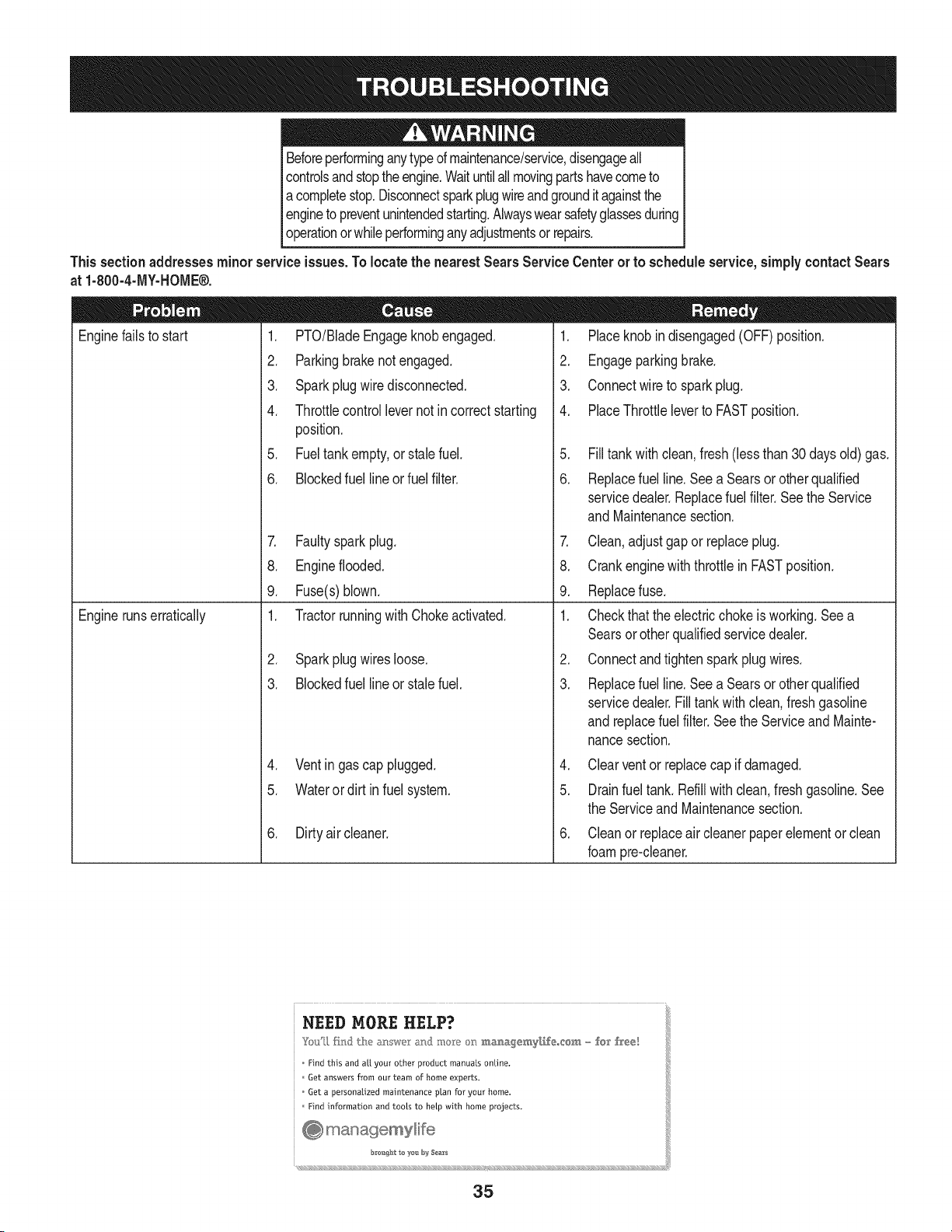
Beforeperforminganytypeof maintenance/service,disengageall
controlsandstoptheengine.Waituntilallmovingpartshavecometo
acompletestop.Disconnectsparkplugwireandgrounditagainstthe
I engineto preventunintendedstarting.Alwayswearsafetyglassesduring
l operationor whileperforminganyadjustmentsor repairs.
Thissectionaddresses minor serviceissues.Tolocate the nearest Sears Service Centeror to scheduleservice,simplycontactSears
1. PTO/BladeEngageknobengaged.
2. Parkingbrakenotengaged.
3. Sparkplugwire disconnected.
at 1-800-4-MY-HOME®.
Enginefailsto start
Enginerunserratically
4. Throttlecontrollevernot in correct starting
position.
5. Fueltank empty,or stale fuel.
6. Blockedfuel line orfuel filter.
1. Placeknobin disengaged(OFF)position.
2. Engageparkingbrake.
3. Connectwireto sparkplug.
7. Faultysparkplug.
8. Engineflooded.
9. Fuse(s)blown.
4. PlaceThrottleleverto FASTposition.
5. Filltank with clean,fresh (less than 30 days old) gas.
6. Replacefuel line.See a Searsor otherqualified
servicedealer.Replacefuelfilter. Seethe Service
1. TractorrunningwithChokeactivated.
2. Sparkplugwires loose.
3. Blockedfuel line or stalefuel.
4. Ventingas cap plugged.
5. Wateror dirt in fuel system.
6. Dirtyair cleaner.
andMaintenancesection.
7. Clean,adjustgap or replaceplug.
8. Crankenginewith throttlein FASTposition.
9. Replacefuse.
1. Checkthatthe electricchokeis working.Seea
Searsorotherqualifiedservicedealer.
2. Connectandtighten spark plugwires.
3. Replacefuel line.See a Searsor otherqualified
servicedealer.Filltankwithclean,freshgasoline
andreplacefuelfilter. Seethe Serviceand Mainte-
nancesection.
4. Clearventor replacecap if damaged.
5. Drainfuel tank. Refillwith clean,fresh gasoline.See
the Serviceand Maintenancesection.
6. Cleanor replaceair cleanerpaper elementor clean
foampre-cleaner.
• lili
NEED MORE HELP?
Find this and a[[ your other product manuals online.
Get answers from our team of home experts.
Get a personalized maintenance plan for your home.
Find information and toots to hetp with home projects.
b es_t _e yon f}y Sea_s
35

Engineoverheats 1. Engineoil levellow
2. Air flowrestricted
.
2.
Enginehesitatesat highRPMs 1. Sparkpluggap settoo close 1.
Engineidles poorly 1. Fouledspark plug 1.
2. Dirtyair cleaner 2.
Excessivevibration 1. Cuttingbladeslooseor unbalanced 1.
2. Damaged,dull,or bentcuttingblade 2.
Unevencut 1. Decknot leveledproperly. 1.
2. Dullblade. 2.
3. Uneventire pressure. 3.
Fillenginewith properamountandtype of oil.
Cleangrassclippingsanddebrisfromaroundthe
engine'scoolingfinsandblowerhousing.
Removesparkplugandadjustgap.
Replacesparkplugandadjustgap.
Cleanor replaceair cleanerelementand/orclean
pre-cbaner.
Tightenbladeandspindle.Balanceblade.
Replaceblade.
Performside-to-sidedeckadjustment.
Sharpenor replaceblade.
Checktire pressureinallfour tires.
....... L
NEED MORE HELP?
Find this and a[[ your other product manuals online,
Get answers from our team of home experts.
Get a persona[ized maintenance plan for your home.
Find information and tools to help with home projects,
@ managemylife
bI'_u_htte yes b_4Sea_
_ (((((((((((((((((((((((((((S ((((((((((((((((((((((((
36

37
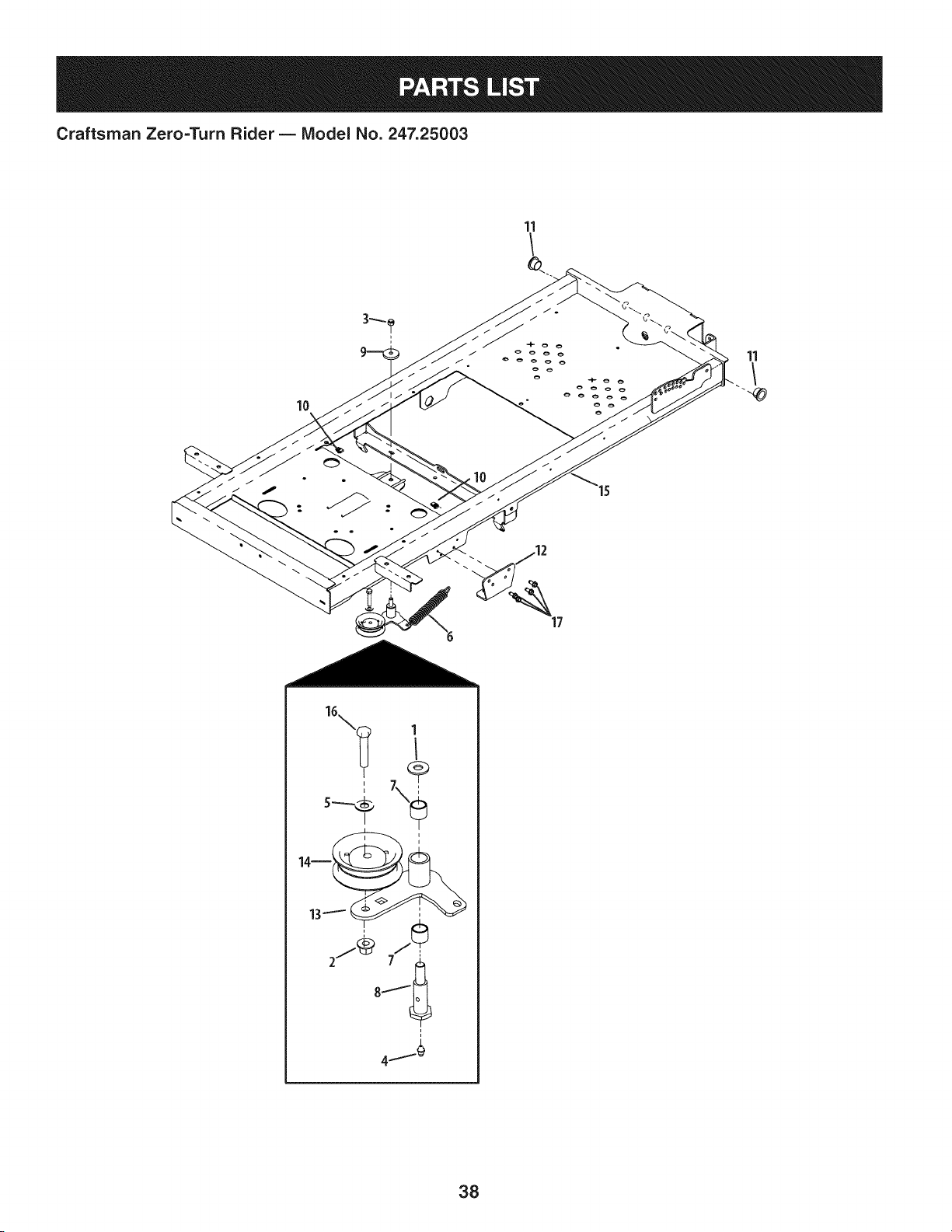
Craftsman Zero=Turn Rider B IViodel No. 247.25003
11
11
"4
i
1
I
14--
13
j_ 77_
38

Craftsman Zero=Turn Rider B IViodel No. 247.25003
00006168
2 00022560
3 712-0290
4 00060078
5 00061053
6 01000199
7 01000308
8 738-3108
9 01003269
10 01008539P
11 02002628
02002641-
12
0637
13 02003641
14 02004558
02004865-
15
0637
16 710-0347
17 710-04484
D = 0
FlatWasher,3/8
iFlangeLockNut,3/8-16
NylockNut,7/16-14
GreaseFitting,1/4-28x 3/16
iWasher,3/8
ExtensionSpring,1.00x 5.00
BearingSleeve
ShoulderBolt
iFlatWasher,7/16x 1.75
iU-Nut,1/4-20
BronzeBushing,.875x 1.50
TransmissionMountingBracket
IdlerArm
FlatIdlerPully
FrameAssembly
iHexCapScrew,3/8-16x 1-3/4
iSelfTappingScrew,5/16-18x .750
39
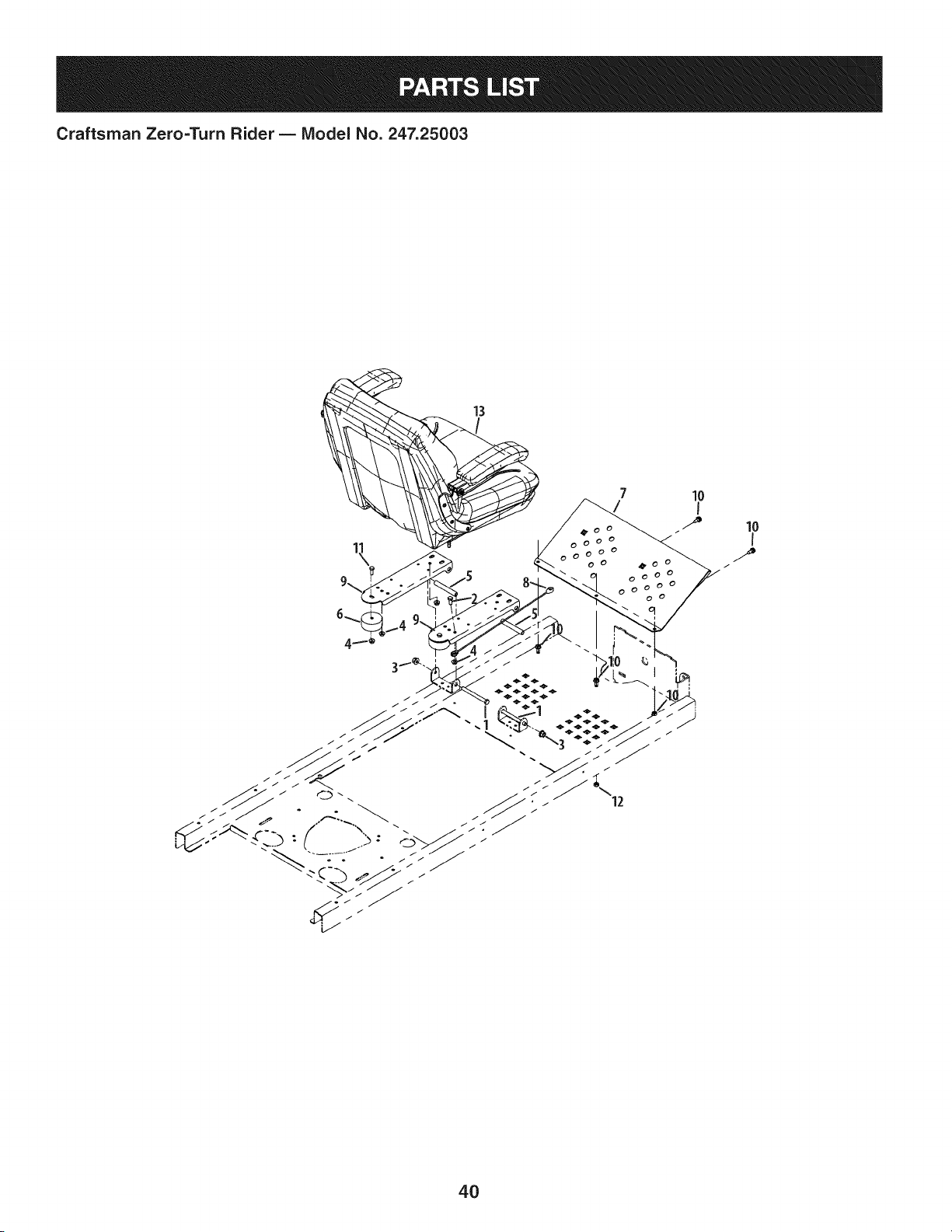
Craftsman Zero=Turn Rider B Model No. 247.25003
7
4_0 o
0000
000 O0
10
I
/
/
4O

Craftsman Zero=Turn Rider B Model No. 247.25003
00011925
2 00013406
3 00022560
4 712-3004A
5 01009872
6 02002952
02002960-
7
0637
8 02004062P
703-06691-
9
0637
10 710-04484
11 710-3008
12 912-0429
13 757-04115
-- 02002255
D = O
HexCapScrew,3/8-16x 4.00
iHexCapScrew,5/16-18x 3/4
iFlangeLockNut,3/8-16
iFlangeLockNut,5/16-18
Spacer,.370IDx .500x 3.45
iBumper,2.50 x 1.13
FootRestBracket
LiftCable
SeatMountingBracket
iSelfTappingScrew5/16-18x .750
iHexCapScrew,5/16-18x .75
NylockNut,5/16-18
Seat
ArmrestKit
41
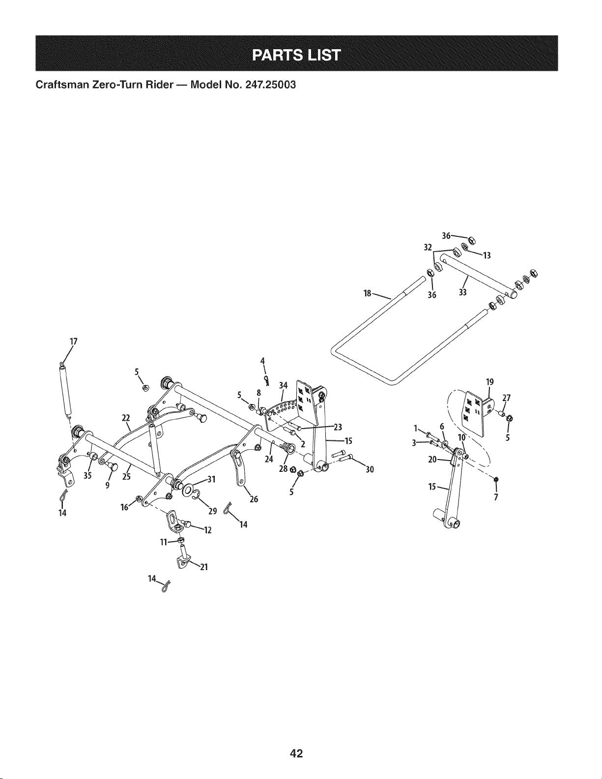
Craftsman Zero=Turn Rider B IViodel No. 247.25003
17
t
\
\
7
42

Craftsman Zero=Turn Rider B IViodel No. 247.25003
00008495
2 00011438
3 00013416
4 00021956
5 00022560
6 00083192
7 912-3027
8 01003468
9 01003536
10 01007312
11 01008658
12 02000393
13 02000671
14 02000673
15 02002374
16 02002382
17 02002629
18 02002879
02002880-
19
0637
20 02002882
21 02002890
22 02002893
23 02002907
24 02002915
25 02002916
26 02002979
27 02003436
28 02003685
29 02003716
30 02003717
31 02003720
32 02003751
33 02004227
02004694-
34
0637
35 02005535
36 912-3015
D = O
HexScrew,3/8-16x 1.75
HexScrew,3/8-16x 1.50
HexScrew,1/4-20x 1.00
iHairPin,3/8 x 1.562x .080
iFlangeCounterLockNut,3/8-16
iWasher,.390x 1.00x .180
iFlangeTopLockNut, 1/4-20
Spacer,.375x .500x .750
ShoulderBolt,3/8-16x .625x .830
Spacer,.385x .625x .500
iJamNut, 1/2-20
iShoulderBolt,3/8-16x .56x .27
LockWasher,.633x 1.07x .161
iHairPin, 1/2x 1.625x .125
iFootLiftPivotAssembly
iAdjustableDeckLift Bracket
ExtensionSpring,.75x 7.89x .14
FrontLift Rod
FootPedalAssembly
iTorsionSpring,.900x 2.3 x .09
LowerBracketAssembly
LiftConnectingLink
iClevisPin,3/8 x 2.05
FrontShaftAssembly
RearShaftAssembly
iCurvedLinkPlate
Spacer,.380x .500x .667
iHexFlangeBearing,7/8
iRetainingClip,.675
iSocketCapScrew,3/8-16x 1.50
iWasher,.940x 1.75x .110
Spacer,.635x 1.2x .41
iTrailingLinkPivotRod
iIndexPlate
Spacer,632x .877x .548
JamNut,5/8-11
43
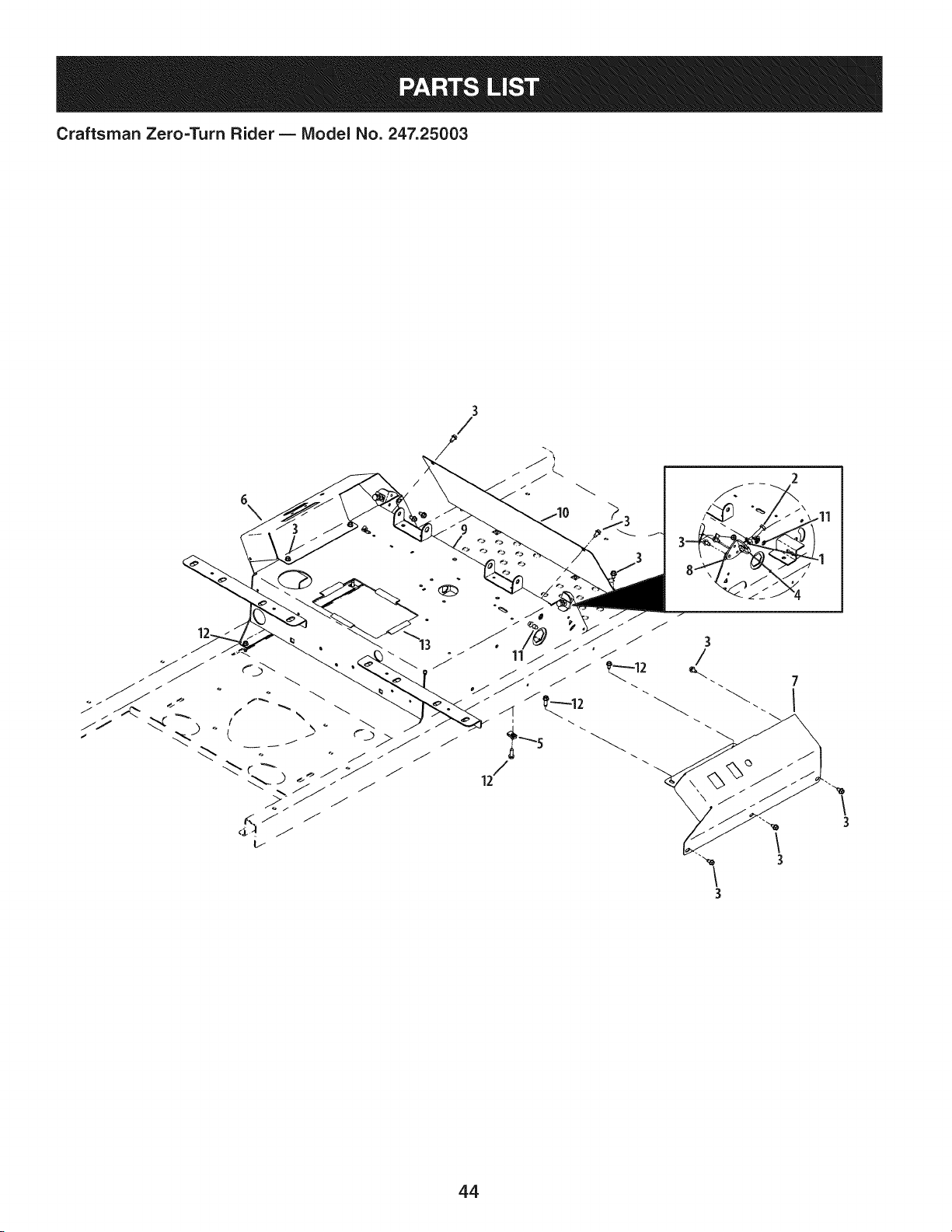
Craftsman Zero=Turn Rider B IViodel No. 247.25003
7
I
44

Craftsman Zero=Turn Rider B IViodel No. 247.25003
2
3
4
5
6
7
8
9
10
11
12
13
00012166
00013116
710-0599
01003563
01008539P
02002735-
0637
02002736-
0637
02002761
680-00048-
0637
703-07000
710-04484
710-0642
735-04130
D = _ e
HexNut,5/16-18
HexScrew,5/16-18x 1-1/4
iScrew,1/4-20x 1/2
iU-Nut,5/16-18
iU-Nut,1/4-20
LeftHandControlConsole
RightHandControlConsole
Forward/ReverseStopBracket
ControlHousingWeldment
FrontPanel
iSelf-TappingScrew5/16-18x .750
iSelf-TappingScrew,1/4-20x .75
iBatteryEdgeTrim
45
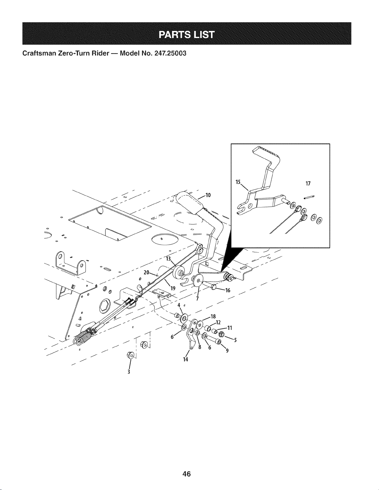
Craftsman Zero=Turn Rider- IViodel No. 247.25003
o
17
46

Craftsman Zero=Turn Rider B IViodel No. 247.25003
00005530
2 00012158
3 00022560
4 01000101
5 712-3004A
6 01002710
7 01009253
8 02002885
9 02003717
10 02003740
11 02003839
12 02003840
13 02004045
14 02004174
15 680-00049
16 710-0520
17 914-0474
18 736-3089
19 946-04564
20 946-04565
D = 0 O
FiatWasher,.406x .812x .062
FlatWasher,3/8
iHexNut,3/8-16FlangeLock
SlideWasher
iFlangeLockNut,5/16-18
iWasher,.375x .738x .063
FiatWasher,.390x 1.5x .134
Spacer,.380x .563x .196
SocketHeadCap Screw,3/8-16x 1.50
iParkingBrakeGrip
Spacer,.322x .438x .44
Spacer,.442x .563x .405
iStepHub,.379x 1.5x .257/.400
LockoutLeverPlate
BrakeHandle
HexHeadCap Screw,3/8-16x 1.50
iCotterPin,1/8x .75
iWasher,.345x 1.00x .100
LeftHandBrakeCable
IRightHandBrakeCable
4.7
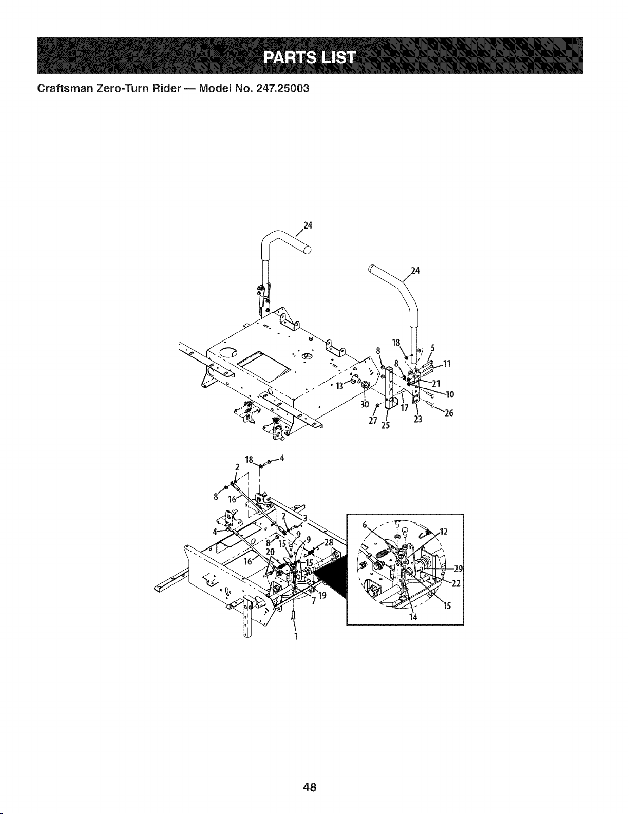
Craftsman Zero=TurnRider B IViodel No. 247.25003
24
24
27 23
2
1
14
48

Craftsman Zero=Turn Rider B IViodel No. 247.25003
00011438
2 00012169
3 00012180
4 00013116
5 00013198
6 00022560
7 936-0463
8 712-3004A
9 01001919
10 912-3027
11 01006898
12 02002684
13 02002723
14 02002844
15 02002885
16 02002992
17 02002994
18 02003419
19 02003560
20 02003568
21 02003644
22 02003716
02003853-
23
0637
24 02003855
680-00050-
25
0637
26 710-0262
27 912-0429
28 732-04610
29 936-0287
D = O
HexCapScrew,3/8-16x 1-1/2
FlatWasher,5/16
HexHeadCap Screw,5/16-18x 1.00
HexScrew,5/16-18x 1-1/4
iHexCapScrew,5/16-18x 2.00
iFlangeLockNut,3/8-16
FlatWasher,1.4x .630x .0515
iLockNut,5/16-18
ShoulderScrew,1/4-28
iHexFlangeLockNut, 1/4-20
iHexCapScrew,1/4-20x 2.00
BrakeLeverPlate
iSteeringInputShaftAssembly
Spacer,.385x .625x .869
Spacer,.380x .563x .196
iSteeringLinkRod
SocketHeadCap Screw,5/16-18x 1.25
iBushing,.310x .172x .688x .06
ControlLockRod
ControlCableLockOut
Spacer,.25 x .38 x 1.13
iE-ClipRetainerRing
iLapbarPivotBracket
iLapbarHandle/GripAssembly
PivotBracketWeldment
iCarriageBolt,5/16-18x 1.50
NylockNut,5/16-18
ExtensionSpring,.544x 3.35
FlatWasher,.793x 1.24x .060
30 941-0598 i Hex FlangeBearing,.752
49
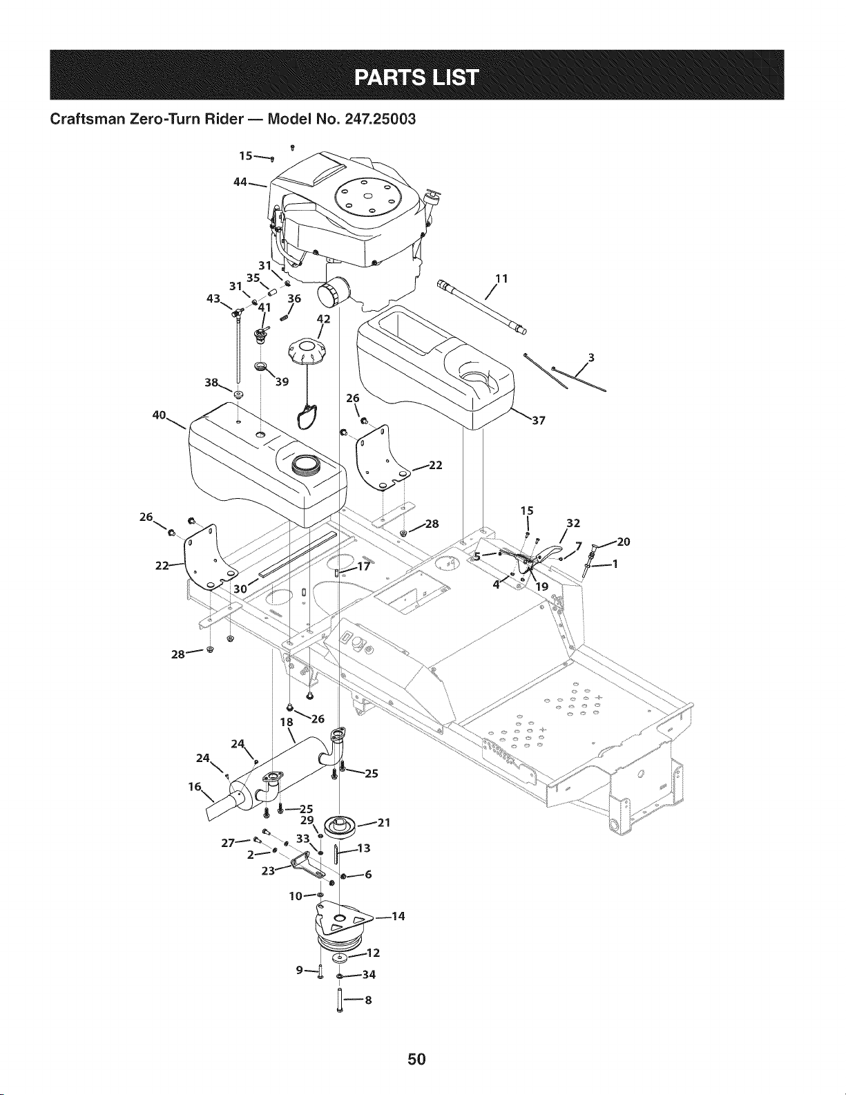
Craftsman Zero=Turn Rider B Model No. 247.25003
43
31
31 35\
4
26
18 _26
24 24\
32
7_120
5O

Craftsman Zero=Turn Rider B IViodel No. 247.25003
00011453 JamNut,3/8-24
2 00012169 i Washer,344 x .688x .063
3 725-0157 CableTie
4 00014608 NylockNut,#10-32
5 00060056 i Nut,#8-32
6 712-3004A iFlangeCounterLockNut,5/16-18
7 710-3217 iMachineScrew,#8-32 x .356
8 710-0510 Hex Screw,7/16-20x 3.00
9 710-0458 iCarriageBolt,5/16-18x 1.75
10 01002710 iWasher,.406x .750x .063
11 01003283 iOil DrainHose
12 736-04131 i Washer,.438x 1.745x .250
13 01007533 iBevelKey,.250x .250x 2.75
14 01008434P PTO
15 01008531P iScrew,#10-32x.500
16 01008623 iStraightExhaustPipe
17 01009243 iFlangeScrew,3/8-16x .875
18 02000456 KohlerMuffler
19 02000477 iThrottleControlCable
20 02000478 ChokeCable
21 02003417 TransmissionPulley
603-04912-
22 0637 iFuelTankMountingBracketAssembly
23 703-07213 PTORetainerBracket
24 910-0224 HexWasherScrew,#10-16x .500
25 710-04048 iHexFlangeScrew,5/16-18x 1.0
26 710-05361 iHexFlangeScrew,M10-1.5x .500x 8.8
27 710-3008 HexScrew,5/16-18x .75
28 712-04065 iFlangeLockNut,3/8-16
29 712-3007 i Jam Nut,5/16-18
30 721-04382 iFoamTape.75x 25
31 726-0205 HoseClamp,.490
32 731-04914 ThrottleControlKnob
33 936-0119 LockWasher,5/16
34 936-0171 LockWasher,7/16
35 751-10349 LowPermeationFuel Hose,1/4
36 751-12089 MonoVent Hose,3/16
37 951-12559 iUtilityBin
38 735-04065 FuelTankBushing
39 735-04081 RubberGrommet,23.0x 3.55
40 951-04318A FuelTank
41 751-12118 FuelRolloverValve
42 951-12193A iFuelCap
43 751-12478 FuelPick-UpFitting(On/Off)
44 KH-SV840-3021iReplacementEngine
51
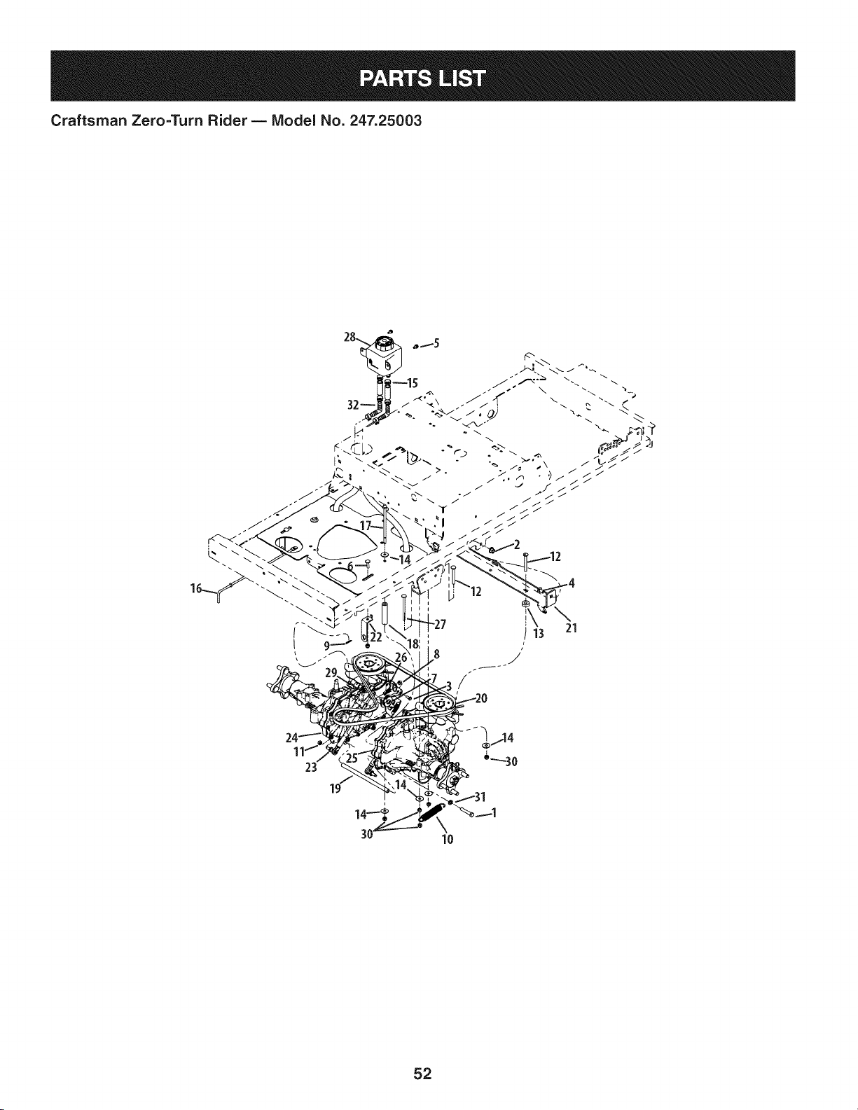
Craftsman Zero=Turn Rider B Model No. 247.25003
\
21
i
52

Craftsman Zero=Turn Rider B IViodel No. 247.25003
00012172
2 00022560
3 710-0751
4 710-3178
5 710-0599
6 01000641
7 01001919
8 912-3027
9 914-0104
10 01002874
11 01003561
12 01005340
13 750-3119
14 01009937
15 02001111
16 02001332
17 02001556
18 02002646
19 02002647
20 02002648
02002679-
21
0637
02002965-
22
0637
23 02003622
24 02004678P
25 02004679P
26 02004681
27 02005326
28 631-04286
29 712-04177
30 912-0429
31 936-0169
32 737-04342
m = I!
HexScrew,3/8-16x 2.00
iFlangeCounterlockNut,3/8-16
HexScrew,1/4-20x .620
iCarriageBolt,3/8-16x .75
iHexFlangeScrew,1/4-20x .500
iCarriageBolt,5/16-18x 1.00
ShoulderBolt, 1/4-28x .38 x .465
iFlangeToplockNut, 1/4-20
iHairPin, 1/8x 1.125x .072
ExtensionSpring,.865x 4.7x .12
NylockNut, M8-1.25
iCarriageBolt,5/16-18x 2.75
Spacer,.406x 1.00x .38
iWasher,.313x 1.06x .062
HoseClamp,.750
iPumpRelayRod
HexScrew,5/16-18x 6.00
Spacer,.375x .750x 3.30
TransmissionSupportTube
V-Belt
TransmissionBracketWeldment
NeutralBracket
iDamper
LHTransmission
RHTransmission
ControlArm DamperBracket
iCarriageBolt,5/16-18x 4.0
iExpansionTankAssembly
iJamNut, 1/4-28
HexLockNut,5/16-18
LockWasher,3/8
Elbow,90
53
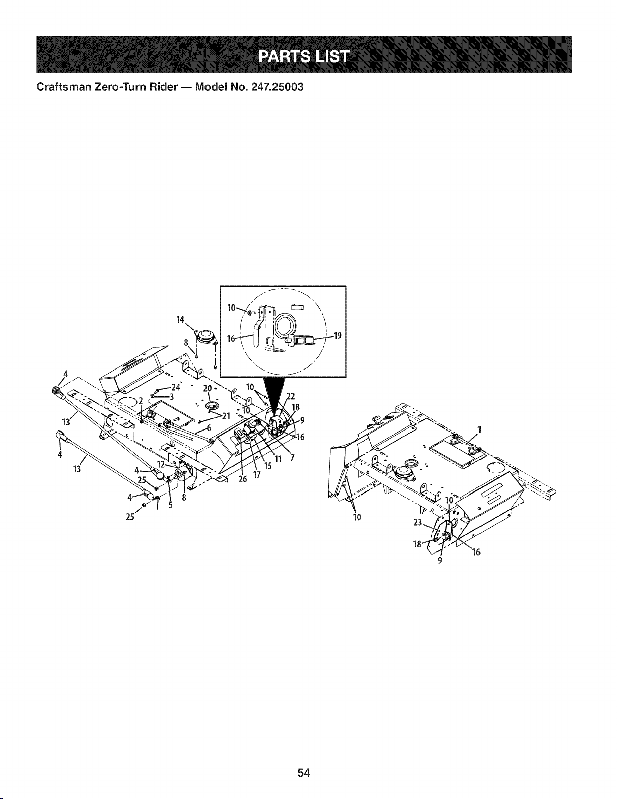
Craftsman Zero=Turn Rider B Model No. 247.25003
14
17
11
18
54

Craftsman Zero=Turn Rider B IViodel No. 247.25003
m = _ 0
925-1707D Battery
2 00012152 NylockNut, 1/4-20
3 00012154 i Washer,.281x .625x .063
4 00013258 BootTerminal,1.00x 2.50
5 00014608 NylockNut,#10-32
6 00024233 i BatteryCable
7 00032097 i Nut,5/8-32
8 710-0599 iHexFlangeScrew,1/4-20x .500
9 01001717 Switch
10 01001864 iFlangeScrew,#10-24x .500
11 01002111 PTOSwitch
12 925-3001 Solenoid
13 01002252 iBatteryCable
14 01003277 SeatSwitch
15 01003581P IgnitionSwitch
16 732-04200 RenovatorSpring
17 01009905 PTOBracket
18 01009931 iNut,#10-24
19 02000024P DeltaSwitch
20 02001134 IGrommet,1/8x 1.5x 2.13
21 02003037 ElectricCDTClip
22 02003926 iRHDeckSwitchMountBracket
23 02003927 LH DeckSwitchMountBracket
24 710-3015 HexScrew,1/4-20x .75
25 912-0429 i Hex Lock Nut,5/16-18
26 925-05120A HourMeter
NS 02002990 iWiringHarness
NS 02005213 HarnessAssembly
55
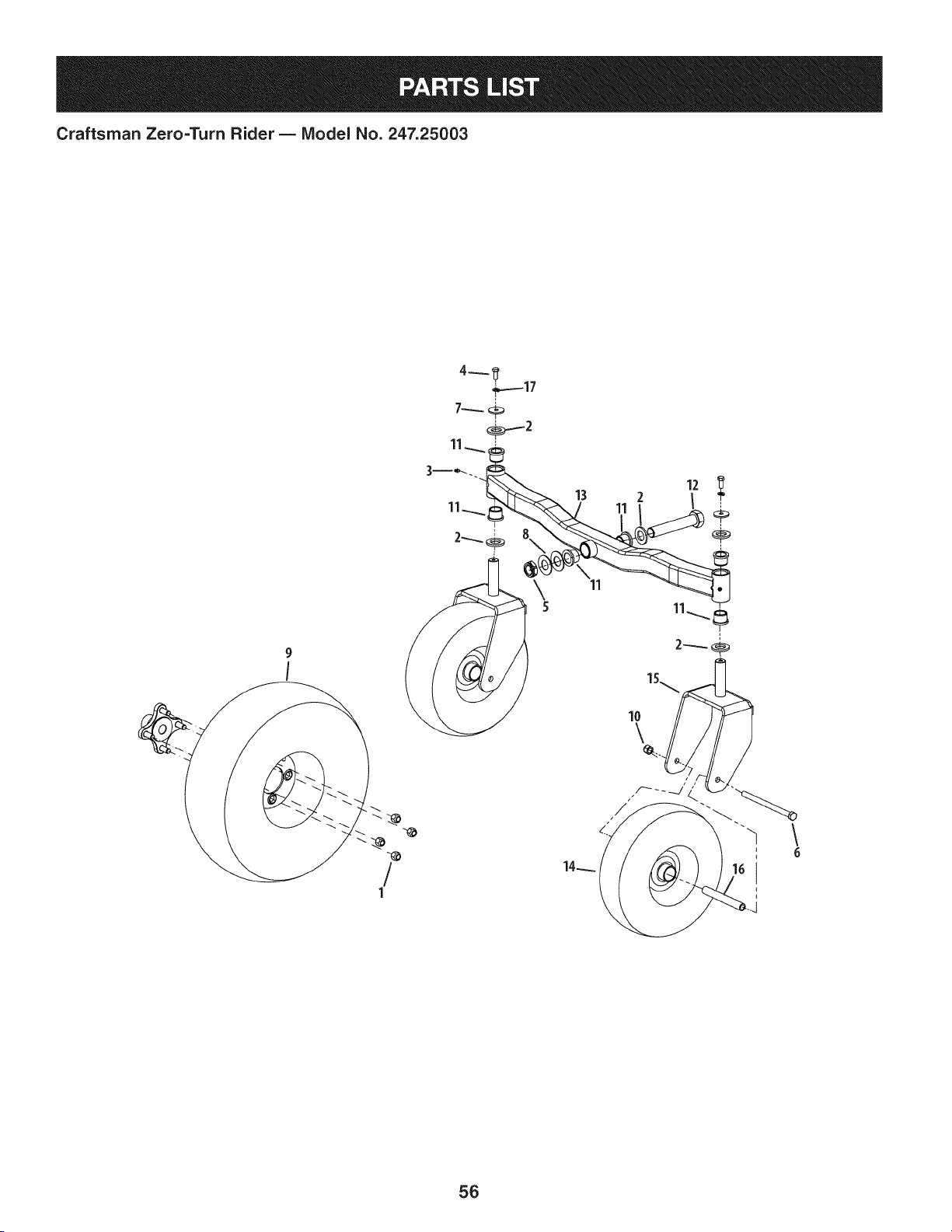
Craftsman Zero=Turn Rider B IViodel No. 247.25003
9
I
!
1
11
56

Craftsman Zero=Turn Rider B IViodel No. 247.25003
00012187
2 00023822
3 00060078
4 710-3001
5 01000678
6 01006961
7 01009253
8 02000588
9 634-04747
-- 02002097
10 02002299
11 741-04488
12 02003804
02004600-
13
0637
14 634-04748
-- 734-04255A
-- 02002105
-- 02002106
-- 02002107
-- 00023806
02005001-
15
0637
16 750-04775A
17 936-0169
D = O O
LugNut, 1/2-20
iWasher,1.00x 1.75x .172
GreaseFitting,1/4-28
HexScrew,3/8-16x .880
iJamNut, 1-14
HexScrew,1/2-20x 7.50
iWasher,.390x 1.50x .122
iWasher,1.00x :2.00x .075
WheelAssy.,20 x 8-10
iTireOnly
NylockNut, 1/2-20
iFlangeBearing,1.001x 1.25
HexScrew,1-14x 5.5
FrontAxleWeldment
WheelAssembly,13x 5-6
iTire Only (Groove),13x 5.0-6
iTireOnly (Smooth),13x 5.0-6
iBeafings
iBushings
GreaseFitting
CastorWheelMountBracketAssy.
Spacer,.51x .75x 5.825
LockWasher,3/8
57
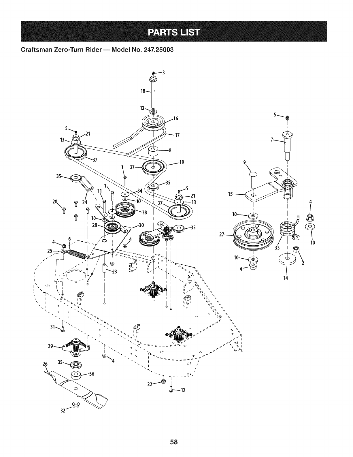
Craftsman Zero=Turn Rider B IViodel No. 247.25003
2O
I
I
13
I
58

Craftsman Zero=Turn Rider B IViodel No. 247.25003
710-3011
2 912-3017
3 737-3004
4 00022560
5 00060078
6 01000199
7 01000302
8 750-05518
9 710-0560
10 736-3052
11 01004127
12 710-3034
13 748-3101A
14 01003269
15 01005737
-- 01000308
16 01005202
17 01009787
18 710-05110A
19 02000154
20 02000762
21 710-05417
22 02000948
23 02003640
24 02003740
25 02004195
26 02005017
27 02005077
28 02005078
29 918-04426
30 853-000029
31 710-3168
32 712-3078
33 732-3067
34 736-3040
35 748-3065A
36 750-05184
37 756-3089
38 02004447
D = O O
HexScrew,3/8-16x 2.00
Nut,3/8-16
GreaseFitting,1/4-28x .788
FlangeCounterLockNut,3/8-16
GreaseFitting,1/4-28
ExtensionSpring,1.00x 5.00x .125
ShoulderBolt,.625x 1.95
Spacer,.760x 2.00 x 1.27
CarriageBolt,3/8-18x 1.75
Washer,.406x 1.00x .105
HexScrew,3/8-16x 3.00
CarriageBolt,3/8-16x 1.25
Spacer,2.0x .75IDx .31
Washer,.438x 1.75x .250
IdlerArmAssembly
SleeveBearing,.628x .753x .625
Pulley
V-Belt
HexScrew,3/4-16x 7.7
V-Belt
HexFlangeScrew,5/16-18x 1.00
HexFlangeScrew,3/4-16x 5.85
FlangeCounterLockNut,7/16-14
Spacer,.390x .625x 1.88
FiatGrip,1.0x 3.2 x .25
SpringMountBracket
Hi-LiftBlade,17.0
IdlerPulley
IdlerPulley
SpindleAssembly
DoubleIdler
CarriageBolt,3/8-16x 1.00
FlangeLockNut,3/4-16
TorsionSpring
Washer,.406x 1.92x .060
DeckSpindleSpacer
Spacer,.760x 2.000x .790
Pulley
IdlerPulley
59
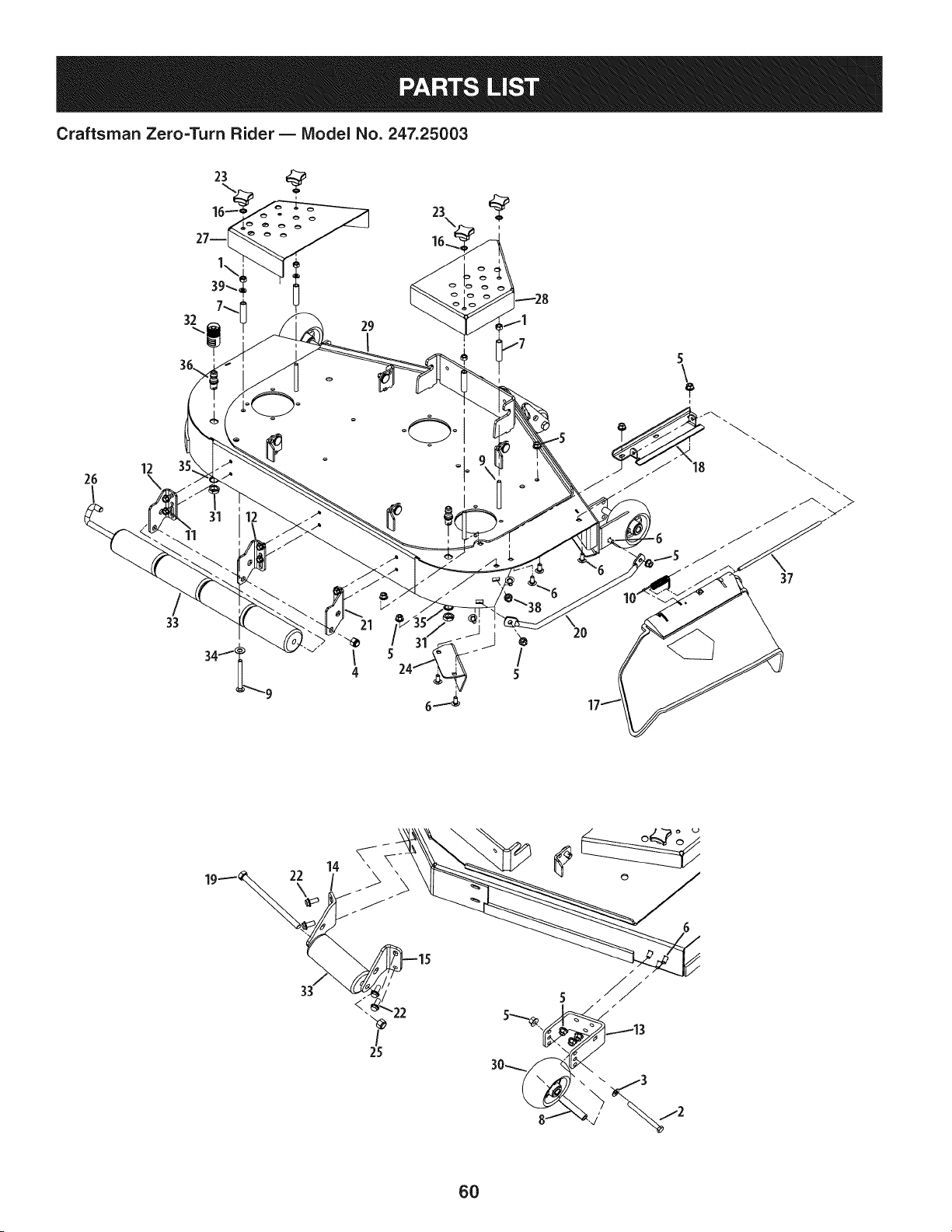
Craftsman Zero=Turn Rider B Model No. 247.25003
26
!
12 35
32
33
i
29
I
/ 5 - /
4 24 5
20
5
37
22 o
?
25
6O

Craftsman Zero=Turn Rider B IViodel No. 247.25003
|= 0 =
912-3017 Nut,3/8-16
2 00011925 HexScrew,3/8-16x 4.00
3 00012158 Washer,.406x .813x .063
4 712-3083 Hex Lock Nut,1/2-13
5 00022560 FlangeCounterLock Nut,3/8-16
6 710-3178 CarriageBolt, 3/8-16x .75
7 01000395 Spacer,.400x .560x 2.45
8 750-3193 Spacer,.390x .620x 3.04
9 710-0521 CarriageBolt, 3/8-16x 3.50
10 732-04797 TorsionSpring,.639x 2.16x .12
11 01004304 FlangeScrew,3/8-16x .500
01004707-
12 RollerMountBracket
0637
01005243-
13 0637 Anit-ScalpFrontMountBracket
02004497-
14 LH FrontRollerMountBracket
0637
02004500-
15 RHFrontRollerMountBracket
0637
16 01005851 Washer,.398x .694x .032
17 01006693P ChuteDeflector
01006748-
18 ChuteDeflectorBracket
0637
19 01006961 HexScrew,1/2-20x 7.50
20 01008644 FingerGuard
01008790-
21 RHRollerMt.Bracket
0637
22 01009243 FlangeScrew,3/8-16x .875
23 02000040 PlasticKnob,3/8-16
02001235-
24 MicroChuteBaffle
0637
i25 02002299 Nut,1/2-20
i26 02002799 J-Hook
02003605-
27 LHBelt Cover
0637
02003606-
28 RHBeltCover
0637
02005231-
29 0637 DeckAssembly
i30 634-3159 Wheel
i31 912-0641 HexNut
i32 921-04041 WaterNozzleAdapter
i33 731-3005 FrontRoller
i34 936-0272 FlatWasher,.510x 1.00x .060
i35 936-0760 LockWasher,17x 23.8x 1.95
i36 737-04003D WaterDeck Nozzle
i37 747-3384 ChuteDeflectorRod
i38 712-04065 Nut,FlangeLock,3/8-16
i39 936-0169 LockWasher,3/8
61
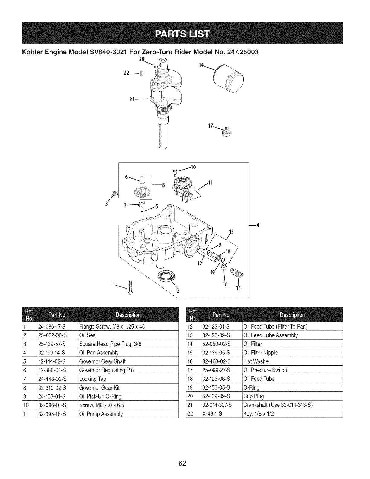
Kohler Engine IViodel SV840=3021 For Zero=Turn Rider IViodel No. 247.25003
@
22_ D
13
24-086-17-S FlangeScrew,M8x 1.25x 45
i2 25-032-06-S Oil Seal 13
i3 25-139-57-S SquareHeadPipePlug,3/8 14
i4 32-199-14-S Oil PanAssembly 15
i5 12-144-02-S GovernorGearShaft 16
i6 12-380-01-S GovernorRegulatingPin 17
i7 24-448-02-S LockingTab 18
8 32-310-02-S GovernorGearKit 19
9 24-153-01-S Oil Pick-UpO-Ring 20
10 32-086-01-S Screw,M6 x .0x 6.5 21
11 32-393-16-S Oil PumpAssembly 22
32-123-01-S
32-123-09-S
52-050-02-S
32-136-05-S
32-468-02-S
25-099-27-S
32-123-06-S
32-153-05-S
52-139-09-S
32-014-307-S
X-43-1-S
Oil FeedTube(FilterToPan)
Oil FeedTubeAssembly
Oil Filter
Oil FilterNipple
FlatWasher
Oil PressureSwitch
Oil FeedTube
O-Ring
Cup Plug
Crankshaft(Use32-014-313-S)
Key,1/8x 1/2
62
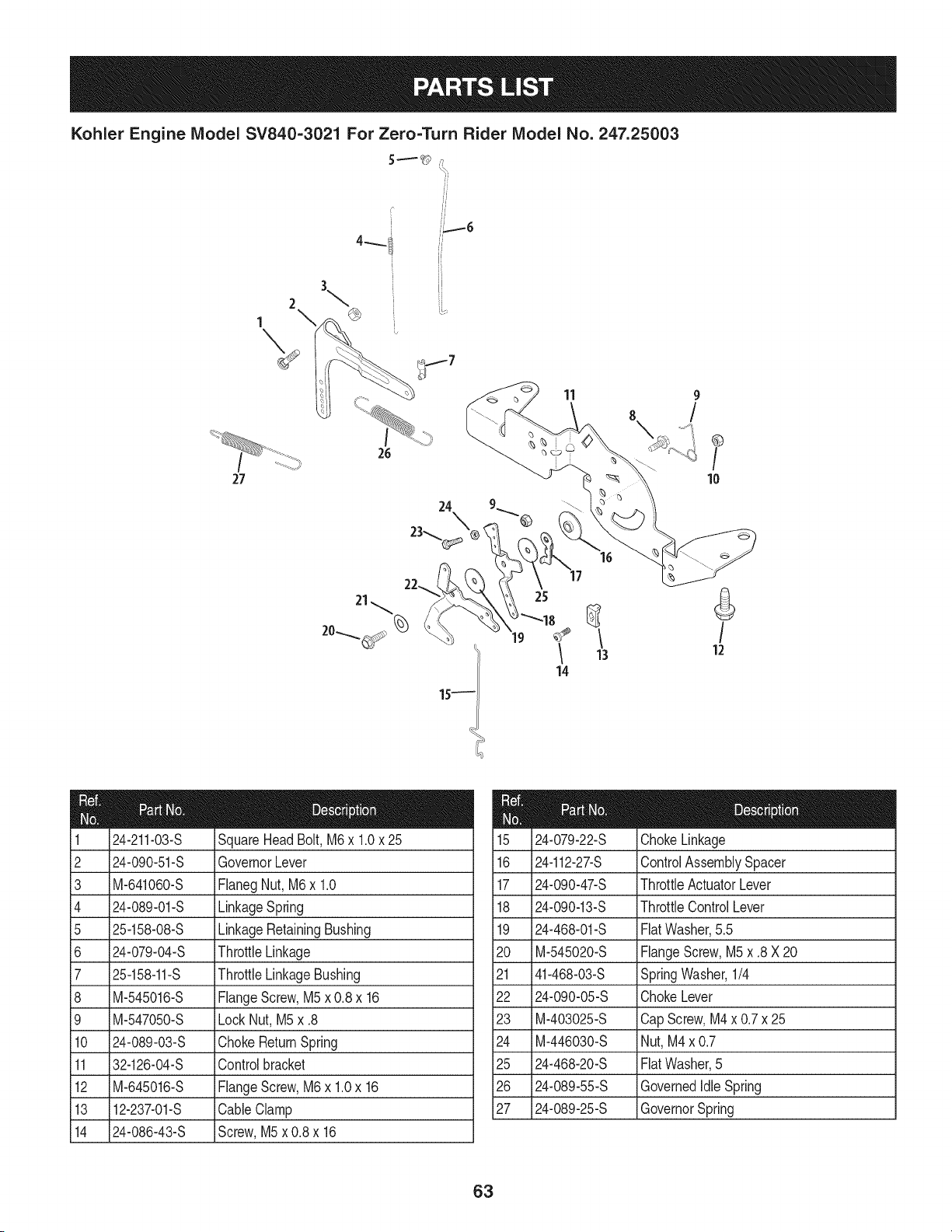
Kohler Engine Model SV840-3021 For Zero=Turn Rider Model No. 247.25003
5 ====== _ ,7
%,
27
r
26
//
_7
11
®
/
10
24
25
16
13 12
14
24-211-03-S SquareHeadBolt,M6x 1.0x 25
2 24-090-51-S GovernorLever
3 M-641060-S FlanegNut,M6x 1.0
4 24-089-01-S LinkageSpring
5 25-158-08-S LinkageRetainingBushing
6 24-079-04-S ThrottleLinkage
7 25-158-11-S ThrottleLinkageBushing
8 M-545016-S FlangeScrew,M5x 0.8x 16
9 M-547050-S LockNut, M5x .8
10 24-089-03-S ChokeReturnSpring
11 32-126-04-S Controlbracket
12 M-645016-S FlangeScrew,M6x 1.0x 16
13 12-237-01-S CableClamp
14 24-086-43-S Screw,M5x 0.8 x 16
24-079-22-S ChokeLinkage
16 24-112-27-S ControlAssemblySpacer
17 24-090-47-S ThrottleActuatorLever
18 24-090-13-S ThrottleControlLever
19 24-468-01-S FlatWasher,5.5
20 M-545020-S FlangeScrew,M5x .8 X 20
21 41-468-03-S SpringWasher,1/4
22 24-090-05-S ChokeLever
23 M-403025-S CapScrew,M4x 0.7x 25
24 M-446030-S Nut,M4x 0.7
25 24-468-20-S FlatWasher,5
26 24-089-55-S GovernedIdle Spring
27 24-089-25-S GovernorSpring
63
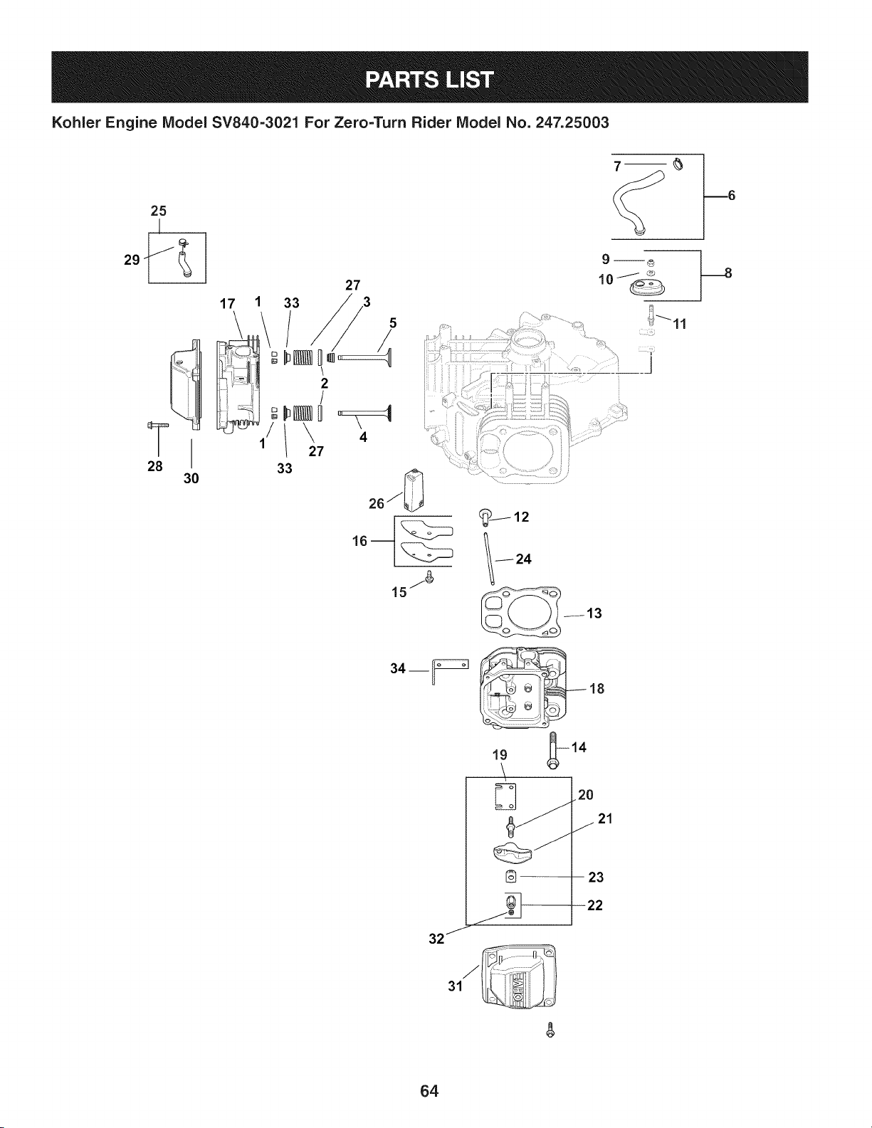
Kohler Engine IViodel SV840=3021 For Zero=Turn Rider IViodel No. 247.25003
28
30
17 1 33
2
/
27
33
4
34__
19 _14
\
2O
21
@-- 23
/
32"
31
64

Kohler Engine IViodel SV840=3021 For Zero=Turn Rider IViodel No. 247.25003
12-755-03 RetainerKit
2 235011-S SpringRetainer
3 66-032-05-S ValveSternSeal
4 24-016-01 ExhaustValve(STD)
5 24-017-01 IntakeValve(STD)
6 32-326-06-S BreatherHoseKit (Inc.#7)
7 25-237-31-S HoseClamp,1/2
8 32-081-02-S HousingBreatherKit (Inc.#9 & 10)
9 M-547050-S LockNut,M5 x 8
10 32-468-01-S SealingWasher
11 32-072-03-S BreatherCoverStud
12 32-019-02-S Tappet
13 32-841-01-S CylinderHeadGasketKit
14 62-086-08-S FlangeScrew,MIOx 1.5x 90
15 M-645016-S FlangeScrew,M6x 1.0x 16
16 32-096-04-S BreatherCover
17 32-318-13-S CylinderHeadAssemblyKit,#1(Inc.
ExhaustMountingHardware)
18 32-318-14-S CylinderHeadAssemblyKit,#2 (Inc.
ExhaustMountingHardware)
19 32-146-09-S GuidePlate
20 32-072-04-S RockerStud
21 32-186-03-S RockerArm
22 32-100-05-S HexNutAssembly(Inc.#32)
23 25-599-01-S RockerArm Pivot
24 32-411-04-S PushRod
25 32-326-07-S FuelPumpHoseKit (Inc. #29)
26 32-050-05-S BreatherFilter
27 32-089-05-S ValveSpring
28 25-086-374-S PanHeadScrew
29 25-237-01-S HoseClamp
30 25-096-10-S RockerCover
31 25-096-09-S RockerCover
32 25-086-168-S SetScrew
33 25-173-28-S ValveSpringCap
34 25-445-03-S LiftingStrap
NS 32-755-03-S CylinderHeadHardwareKit
65
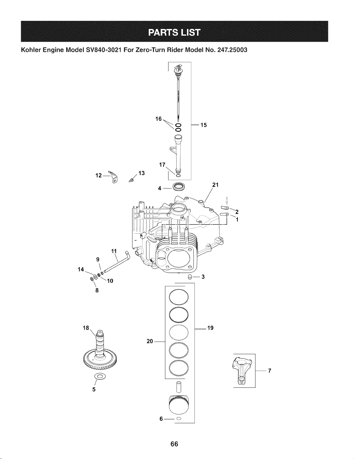
Kohler Engine IViodel SV840=3021 For Zero=Turn Rider IViodel No. 247.25003
17
m15
21
5
20 m
__
O
©
O
©
8
©
m19
66

Kohler Engine IViodel SV840=3021 For Zero=Turn Rider IViodel No. 247.25003
12-402-02 BreatherReed
2 24-018-04-S BreatherReedRetainer
3 24-380-16-S LocatingPin
4 24-032-19-S OilSeal, 1.78x 1.26
5 12-422-07-S CamshaftShim (White,.028)
-- 12-422-08-S CamshaftShim (Blue,.03)
-- 12-422-09-S CamshaftShim (Red,.032)
-- 12-422-10-S CamshaftShim (Yellow,.034)
-- 12-422-11-S CamshaftShim (Green,.036)
-- 12-422-12-S CamshaftShim (Gray,.038)
-- 12-422-13-S CamshaftShim (Black,.04)
6 24-018-01-S PistonPinRetainer
7 24-067-28-S ConnectingRod(STD)
8 24-018-09-S RingRetainer
9 24-468-15-S FlatWasher,11/32
10 28-032-09-S GovernorCrossShaftSeal
11 24-144-38-S GovernorCrossShaft
12 24-126-19 OilFill TubeBracket
13 M-545013-S FlangeScrew,M5x .8 x 13
14 M-931010-S FlatWasher,9mm
15 32-755-04-S Dipstick& TubeKit
16 25-153-09-S O-Ring
17 12-153-01-S LowerOil FillTubeO-Ring
18 32-010-05-S CamshaftAssembly
19 32-874-13-S PistonW/Ring Kit (STD)
20 32-108-01-S RingSet (STD)
21 N/A Crankcase(UseShort Block)
67
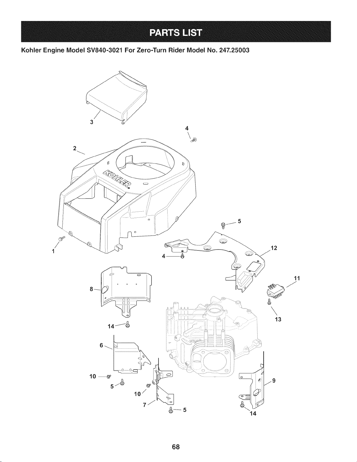
Kohler Engine Model SV840=3021 For Zero=Turn Rider Model No. 247.25003
4
2
8_
14J_
lo- 5Z_ _
10 /
14
11
\
13
68

Kohler Engine IViodel SV840=3021 For Zero=Turn Rider IViodel No. 247.25003
24-086-12-S TapScrew,M6x 1.7x 18
2 32-027-08-S BlowerHousingKit
3 32-096-14-S Cover
4 M-545016-S FlangeScrew,M5x 0.8 x 16
5 M-645016-S FlangeScrew,M6x 1.0x 16
6 24-063-93-S CylinderBaffleValve,#1
7 24-063-94-S CylinderBaffleValve,#2
8 32-063-10-S SideCylinderBarrelBaffle,#1
9 32-063-12-S SideCylinderBarrelBaffle,#2
10 M-545010-S FlangeScrew,M5x .8 x 10
11 41-403-10-S Regulator/Rectifier
12 32-146-05-S Kit BackingPlate
13 M545020-S Screw,M5 x .8 x 20
14 25-086-158-S FlangeScrew,M6x 1.0x 10
NS 32-113-53-S CouragePro FixedGuardDecal
69
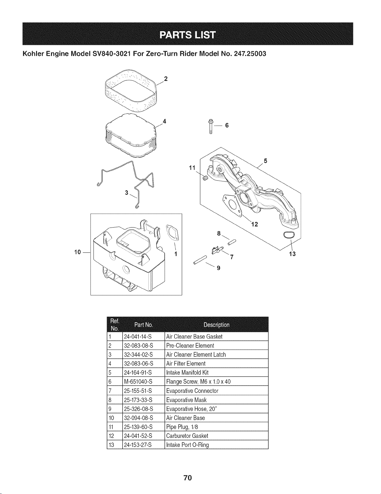
Kohler Engine IViodel SV840-3021 For Zero=Turn Rider IViodel No. 247.25003
11
10m
13
24-041-14-S
2 32-083-08-S
3 32-344-02-S
4 32-083-06-S
5 24-164-91-S
6 M-651040-S
7 25-155-51-S
8 25-173-33-S
9 25-326-08-S
10 32-094-08-S
11 25-139-60-S
12 24-041-52-S
13 24-153-27-S
AirCleanerBaseGasket
Pre-CleanerElement
AirCleanerElementLatch
AirFilterElement
IntakeManifoldKit
FlangeScrew,M6x 1.0x 40
EvaporativeConnector
EvaporativeMask
EvaporativeHose,20"
AirCleanerBase
PipePlug,1/8
CarburetorGasket
IntakePortO-Ring
7O
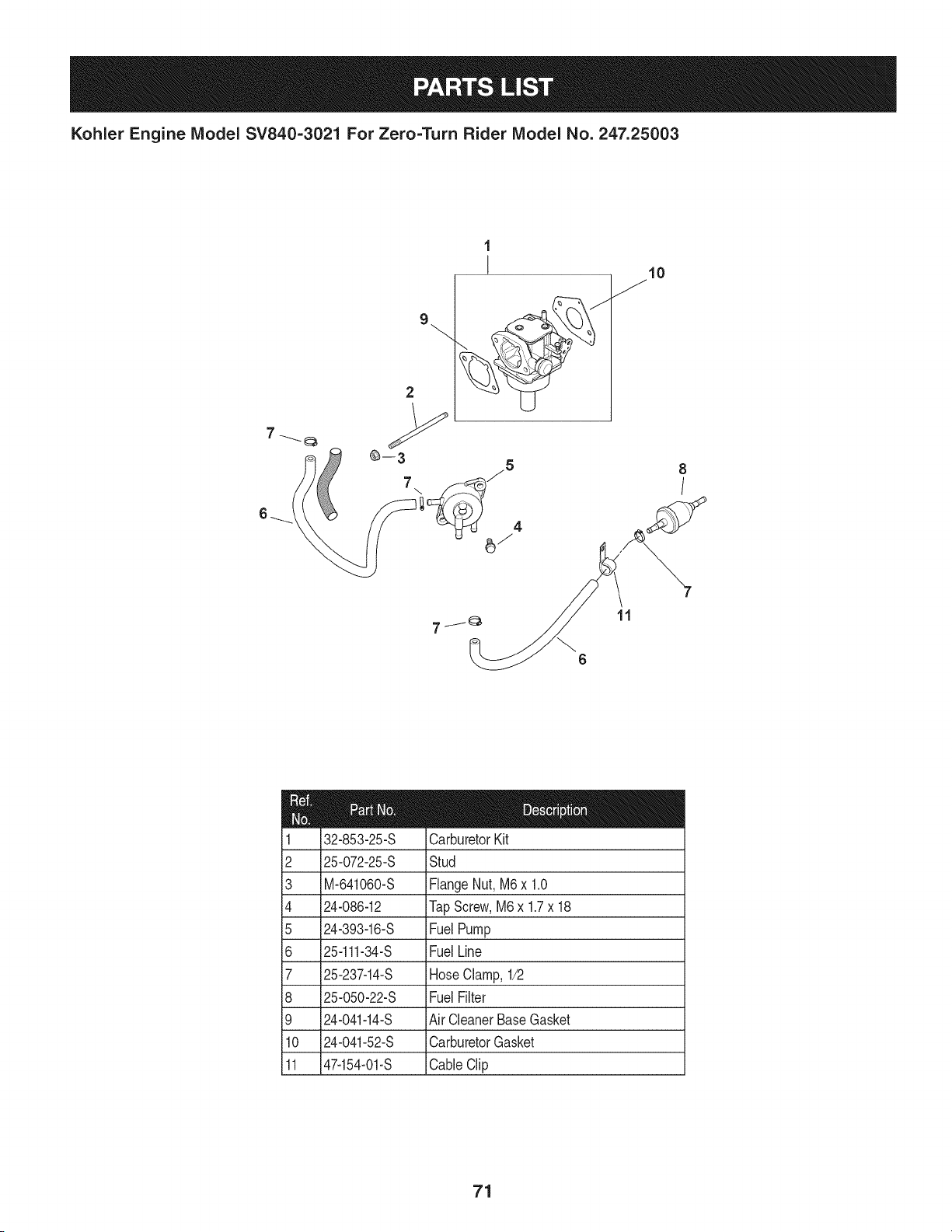
Kohler Engine IViodel SV840=3021 For Zero=Turn Rider IViodel No. 247.25003
7
\
1
!
10
8
f
6
11
2
3
4
5
6
7
8
9
10
11
32-853-25-S
25-072-25-S
M-641060-S
24-086-12
24-393-16-S
25-111-34-S
25-237-14-S
25-050-22-S
24-041-14-S
24-041-52-S
47-154-01-S
CarburetorKit
Stud
FlangeNut,M6x 1.0
TapScrew,M6x 1.7x 18
FuelPump
FuelLine
HoseClamp,1/2
FuelFilter
AirCleanerBaseGasket
CarburetorGasket
CableClip
71
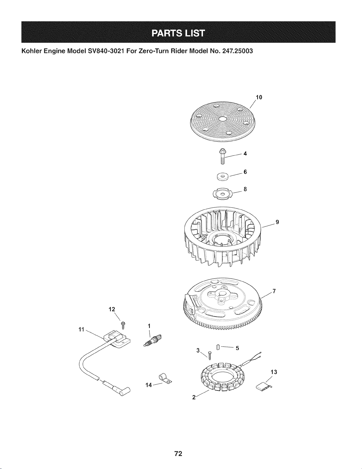
Kohler Engine IViodel SV840=3021 For Zero=Turn Rider IViodel No. 247.25003
4
_6
GJ
j8
j9
3 0_5
72

Kohler Engine IViodel SV840=3021 For Zero=Turn Rider IViodel No. 247.25003
759-3336 SparkPlug
2 237878-S 15/20AmpStatorKit
3 M548025-S Screw,M5 x 0.8x 25
4 25-086-361-S HexFlangeScrew
5 25-340-04-S SquareKey
6 25-468-09-S FiatWasher
7 32-025-15-S FlywheelAssembly
8 20-146-05-S FanMountingPlate
9 32-157-01-S Fan
10 32-162-03-S GrassScreen
11 24-584-63-S ModuleignitionKit
12 M-545020-S Screw,M5 x .8 x 20
13 25-155-41-S Connector
14 47-154-01-S CableClip
N/A 25-454-05-S WireTie
N/A 32-176-26-S WiringHarness
73
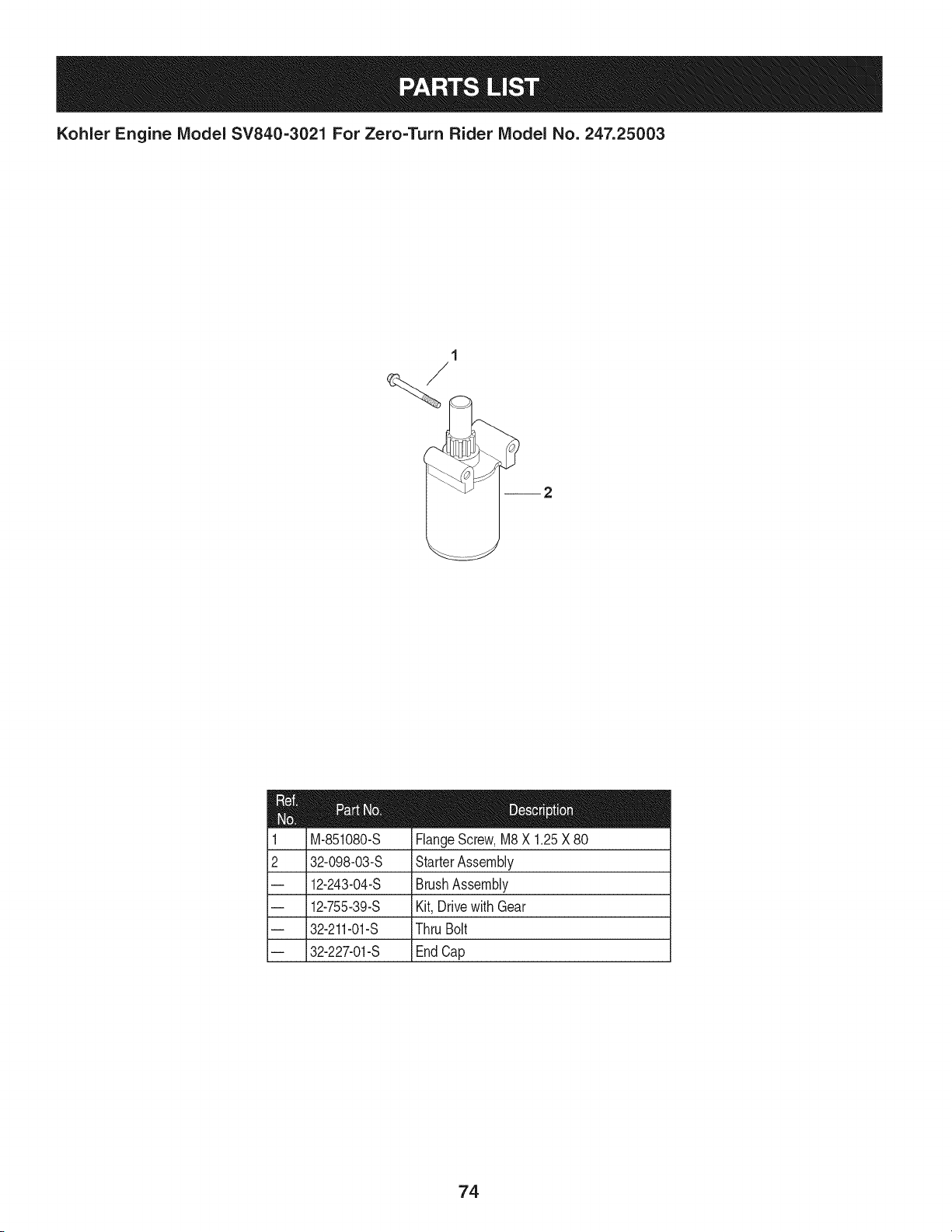
Kohler Engine IViodel SV840=3021 For Zero=Turn Rider IViodel No. 247.25003
1
/
2
M-851080-S
32-098-03-S
12-243-04-S
12-755-39-S
32-211-01-S
32-227-01-S
FlangeScrew,M8X 1.25X80
StarterAssembly
BrushAssembly
Kit,Drivewith Gear
ThruBolt
EndCap
74
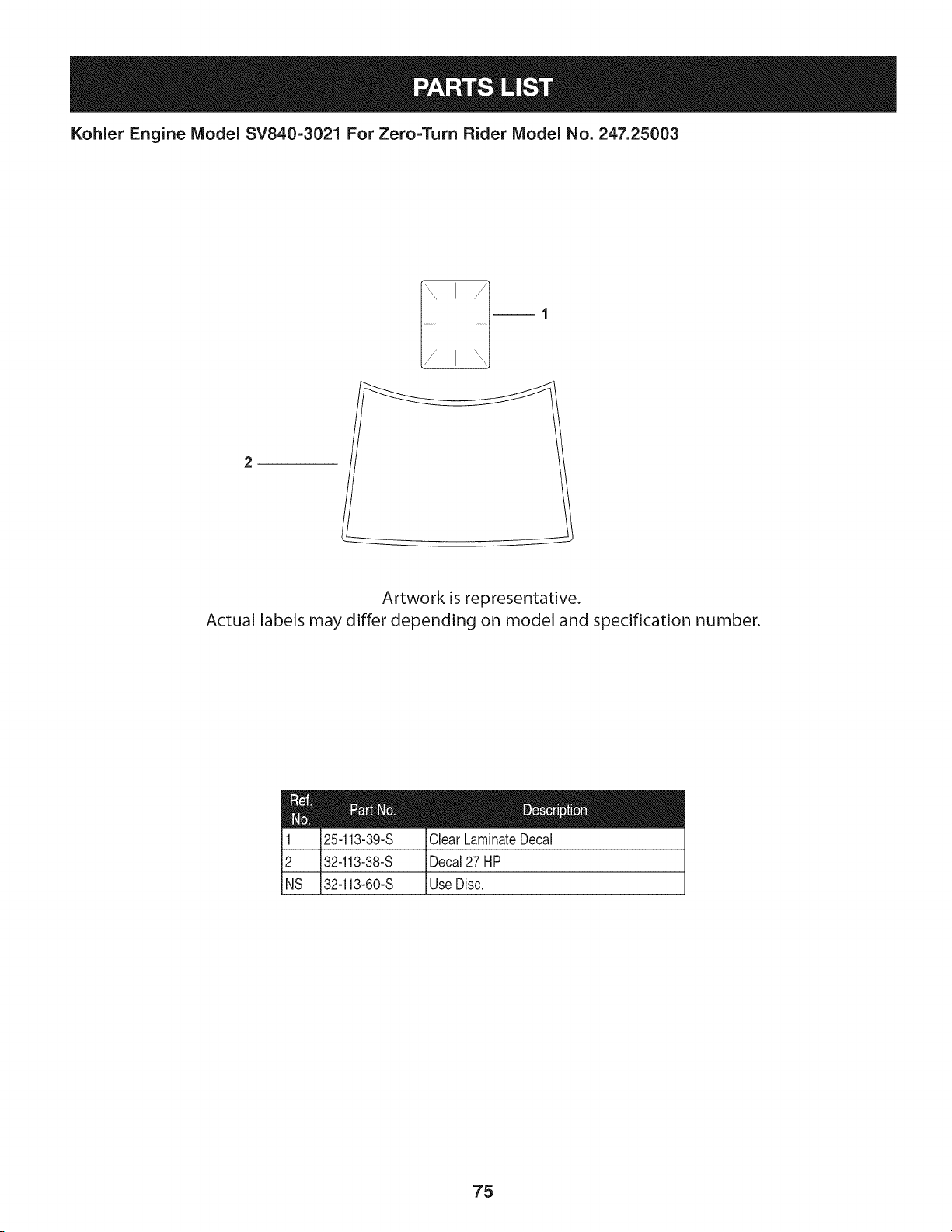
Kohler Engine Model SV840=3021 For Zero=Turn Rider Model No. 247.25003
2
Artwork is representative.
Actual labels may differ depending on model and specification number.
25-113-39-S ClearLaminateDecal
32-113-38-S Decal27 HP
32-113-60-S UseDisc.
75

Craftsman Zero=Turn Rider IViodel 247.
777123711 777123639
PTO BELT ROUTIIqG
777S32842
777D16811
777S33832
777S33184
READOPERATOR'SMANUAL,KEEPSAFETYDEVICESINPLACEANDWORKI_
777S30503
777122444
777D16808
777X44930 (On units produced
on or before Dec. 31,2011)
777X45529 (On units produced
on or after Jan. 1,2011)
MTDCONSUMERGROUPINC.
II This equipment meetsU.S.EPAEVP
II regulations for2012modelyear.
tl EVPFamily:CMTDPNHEQNC1
_ X45529
777D15546
777123640
777D16812
76
777S32328
SHIELD MISSING
DO NOT OPERATE.

77

78

Congratulations on making a smart purchase. Your new Craftsman® product is designed and
manufactured for years of dependable operation. But like all products, it may require repair
from time to time. That's when having a Repair Protection Agreement can save you money and
aggravation.
Here's what the Repair Protection Agreement* includes:
[] Expert service by our 10,000 professional repair specialists
[] Unlimited service and no charge for parts and labor on all covered repairs
[] Product replacement up to $1500 if your covered product can't be fixed
[] Discount of 25% from regular price of service and related installed parts not covered by the
agreement; also, 25% off regular price of preventive maintenance check
[] Fast help by phone - we call it Rapid Resolution - phone support from a Sears representative.
Think of us as a "talking owner's manual."
Once you purchase the Repair Protection Agreement, a simple phone call is all that it takes for you
to schedule service. You can call anytime day or night, or schedule a service appointment online.
The Repair Protection Agreement is a risk-free purchase. If you cancel for any reason during the
product warranty period, we will provide a full refund. Or, a prorated refund anytime after the
product warranty period expires. Purchase your Repair Protection Agreement today!
Some limitations and exclusions apply. For prices and additional information in the U.S.A.
call 1=800=827=6655.
*Coverage in Canada varies on some items. For full details call Sears Canada at 1=800=361=
6665.
Sears Installation Service
For Sears professional installation of home appliances, garage door openers, water heaters, and
other major home items, in the U.S.A. or Canada call 1=800=4=MY=HOME®.
79
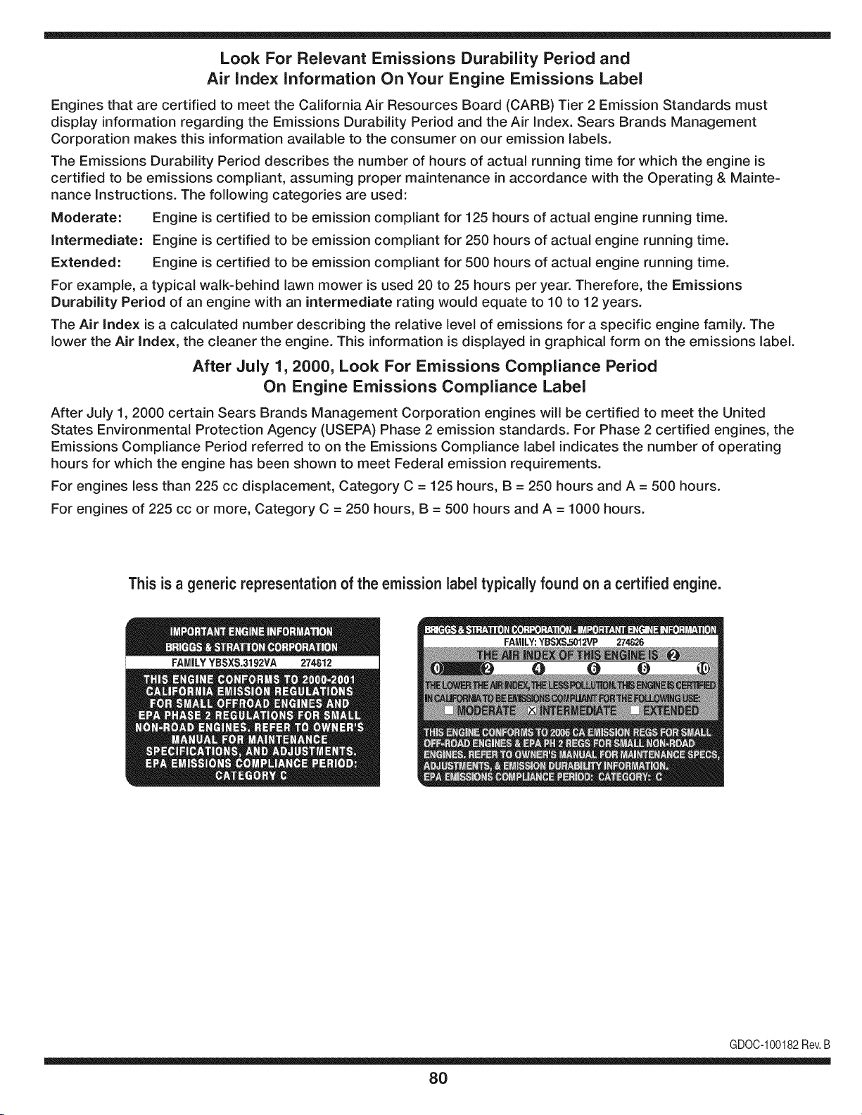
Look For Relevant Emissions Durability Period and
Air index information On Your Engine Emissions Label
Engines that are certified to meet the California Air Resources Board (CARB) Tier 2 Emission Standards must
display information regarding the Emissions Durability Period and the Air Index. Sears Brands Management
Corporation makes this information available to the consumer on our emission labels.
The Emissions Durability Period describes the number of hours of actual running time for which the engine is
certified to be emissions compliant, assuming proper maintenance in accordance with the Operating & Mainte-
nance Instructions. The following categories are used:
Moderate: Engine is certified to be emission compliant for 125 hours of actual engine running time.
Intermediate: Engine is certified to be emission compliant for 250 hours of actual engine running time.
Extended: Engine is certified to be emission compliant for 500 hours of actual engine running time.
For example, a typical walk-behind lawn mower is used 20 to 25 hours per year. Therefore, the Emissions
Durability Period of an engine with an intermediate rating would equate to 10 to 12 years.
The Air index is a calculated number describing the relative level of emissions for a specific engine family. The
lower the Air Index, the cleaner the engine. This information is displayed in graphical form on the emissions label.
After July 1,2000, Look For Emissions Compliance Period
On Engine Emissions Compliance Label
After July 1, 2000 certain Sears Brands Management Corporation engines will be certified to meet the United
States Environmental Protection Agency (USEPA) Phase 2 emission standards. For Phase 2 certified engines, the
Emissions Compliance Period referred to on the Emissions Compliance label indicates the number of operating
hours for which the engine has been shown to meet Federal emission requirements.
For engines less than 225 cc displacement, Category C = 125 hours, B = 250 hours and A = 500 hours.
For engines of 225 cc or more, Category C = 250 hours, B = 500 hours and A = 1000 hours.
This is a generic representation of the emission label typically found on a certified engine.
FAMILYYBSXS.3192VA 274812
GDOC-100182Rev.B
80
(Thispageapplicableinthe U.S.A.and Canadaonly.)
Sears Brands Management Corporation (Sears), the California Air Resources Board (CARD)
and the United States Environmental Protection Agency (U.S. EPA)
Emission Control System Warranty Statement (Owner's Defect Warranty Rights and Obligations)
EMISSIONCONTROLWARRANTYCOVERAGEISAPPLICABLETOCERTI-
FIEDENGINESPURCHASEDIN CALIFORNIAIN 1995ANDTHEREAF-
TER,WHICHARE USED INCALIFORNIA,ANDTOCERTIFIEDMODEL
California and United States Emission
The CaliforniaAir ResourcesBoard(CARD),U.S.EPAand Searsare pleased
to explainthe EmissionControlSystemWarrantyon your modelyear2000and
latersmalloff-roadengine(SORE).InCalifornia,newsmall off-roadengines
mustbe designed,builtand equippedto meettheState'sstringentanti-smog
standards.Elsewherein the UnitedStates, newnon-road,spark-ignition
enginescertifiedfor modelyear 1997and latermustmeetsimilarstandardsset
forth bythe U.S.EPA.Sears mustwarrantthe emissioncontrol systemon your
YEAR 1997AND LATERENGINESWHICHARE PURCHASEDAND USED
ELSEWHEREIN THE UNITEDSTATES(ANDAFTERJANUARY1,2001 IN
CANADA).
Control Defects Warranty Statement
enginefor the periodsoftime listedbelow,providedtherehas been noabuse,
neglector impropermaintenanceof your smalloff-roadengine.Youremis-
sion controlsystemincludespartssuch as thecarburetor,aircleaner,ignition
system,mufflerand catalyticconverter.Also includedmay be connectorsand
otheremissionrelatedassemblies.Wherea warrantableconditionexists,Sears
will repairyour smalloff-roadengineat no costto you includingdiagnosis,parts
and labor.
Sears Emission Control Defects Warranty Coverage
Smalloff-roadenginesarewarrantedrelativeto emissioncontrol partsdefects
fora period of one year,subjectto provisionsset forthbelow.Ifany covered
Owner's Warranty
Asthe smalloff-roadengine owner,you are responsiblefor theperformanceof
therequiredmaintenancelistedin yourOperatingand MaintenanceInstruc-
tions.Searsrecommendsthatyou retain all yourreceiptscoveringmaintenance
on yoursmalloff-roadengine,but Sears cannotdenywarrantysolelyfor the
lackof receiptsor for yourfailureto ensuretheperformanceof all scheduled
maintenance.As the smalloff-roadengineowner,you shouldhoweverbe
awarethat Searsmaydenyyouwarrantycoverageif your smalloff-roadengine
ora part hasfaileddueto abuse,neglect,impropermaintenanceor unap-
parton yourengineis defective,the part will be repairedor replacedbySears.
Responsibilities
provedmodifications.Youare responsiblefor presentingyour smalloff-road
engineto an AuthorizedSearsServiceDealeras soonas a problemexists.The
undisputedwarrantyrepairsshouldbe completedina reasonableamountof
time,not to exceed30 days.Ifyouhaveany questionsregardingyourwarranty
rightsand responsibilities,you shouldcontacta SearsService Representative
at 1-800-469-4663.The emissionwarrantyis a defectswarranty.Defectsare
judgedon normalengineperformance.The warrantyis notrelatedto an in-use
emissiontest.
Sears Emission Control Defects Warranty Provisions
ThefollowingarespecificprovisionsrelativetoyourEmissionControlDefectsWarrantyCoverage.ItisinadditiontotheSearsenginewarrantyfornon-regulated
enginesfound in theOperatingand MaintenanceInstructions.
1. WarrantedParts
Coverageunderthis warrantyextendsonly to the parts listedbelow (the
emissioncontrolsystemsparts)to the extentthese partswere presenton
theenginepurchased.
a. FuelMeteringSystem
• Cold start enrichmentsystem
• Carburetorand internalparts
• FuelPump
b. Air lnduction System
• Air cleaner
• Intakemanifold
c. IgnitionSystem
• Spark plug(s)
• Magnetoignitionsystem
d. CatalystSystem
• Catalyticconverter
• Exhaustmanifold
• Air injectionsystemor pulsevalve
e. MiscellaneousItemsUsedin AboveSystems
• Vacuum,temperature,position,timesensitivevalves
andswitches
• Connectorsandassemblies
2. Lengthof Coverage
Searswarrantsto the initialownerand eachsubsequentpurchaserthat
theWarrantedPartsshallbe free fromdefects in materialsandworkman-
shipwhich causedthe failure of the WarrantedPartsfor a periodof one
yearfromthe datethe engineis deliveredto a retailpurchaser.
3. NoCharge
Repairor replacementof anyWarrantedPartwill beperformedat no
chargeto the owner,includingdiagnosticlabor whichleadsto the
determinationthata WarrantedPartis defective,ifthe diagnosticwork is
performedat anAuthorizedSearsServiceDealer.Foremissionswarranty
servicecontact yournearestAuthorizedSears ServiceDealeras listed in
the "YellowPages"under"Engines,Gasoline,""GasolineEngines,""Lawn
Mowers,"orsimilarcategory.
4. Claimsand CoverageExclusions
Warrantyclaimsshall be filed in accordancewiththe provisionsof the
Sears EngineWarrantyPolicy.Warrantycoverageshall be excludedfor
failuresof WarrantedPartswhichare notoriginal Sears partsor because
of abuse,neglector impropermaintenanceas setforth inthe Sears
EngineWarrantyPolicy.Sears is notliableto coverfailuresof Warranted
Partscausedby the use of add-on, non-original,or modifiedparts.
5. Maintenance
Any WarrantedPart whichis notscheduledfor replacementas required
maintenanceor whichis scheduledonly for regularinspectionto the effect
of "repairor replaceas necessary"shallbe warrantedas to defectsfor the
warrantyperiod.Any WarrantedPartwhich is scheduledfor replacement
as requiredmaintenanceshallbewarrantedas to defectsonly forthe
periodof time upto the first scheduledreplacementfor that part.Any
replacementpart that is equivalentin performanceand durabilitymay
be usedin the performanceof any maintenanceor repairs.The owneris
responsibleforthe performanceof all requiredmaintenance,as definedin
the SearsOperatingand MaintenanceInstructions.
6. ConsequentialCoverage
Coveragehereundershallextend to thefailure of any engine components
caused bythe failureof any WarrantedPartstill underwarranty.
Inthe USAandCanada,a 24 hour hot line, 1-800-469-4663,has a menuof pre-recordedmessagesofferingyou enginemaintenanceinformation.
GDOC-100188Rev.B
81
FEDERAL and/or CALIFORNIA EMISSION CONTROL WARRANTY STATEMENT
YOUR WARRANTY RIGHTS AND OBLIGATIONS
MTDConsumerGroupInc,the UnitedStatesEnvironmentalProtectionAgency (EPA),and, forthose productscertifiedfor sale in the stateof California,the
CaliforniaAir ResourcesBoard(CARB)are pleasedto explainthe emission(evaporativeand/or exhaust)controlsystem(ECS) warrantyonyouroutdoor2006
andlater smalloff-roadspark-ignitedengine andequipment(outdoorequipmentengine)In California,new outdoorequipmentenginesmustbe designed,built and
equippedto meetthe State'sstringentanti-smogstandards(in otherstates, 1997andlater modelyear equipmentmustbedesigned,built,and equippedto meet
theU.S. EPAsmalloff-road, sparkignitionengineregulations.MTDConsumerGroupInc mustwarrantthe ECSon your outdoorequipmentenginefor the periodof
timelisted belowprovidedtherehas been noabuse,neglector impropermaintenanceof outdoorequipmentengine.
Your ECSmay includeparts such as the carburetor,fuel-injectionsystem,the ignitionsystem,catalyticconverter,fuel tanks,fuel lines,fuel caps,valves,canisters,
filters,vapor hoses,clamps,connectors,andotherassociatedemission-relatedcomponents.
Wherea warrantableconditionexists, MTDConsumerGroupIncwill repairyouroutdoorequipmentengine at no cost to youincludingdiagnosis,parts and labor.
MANUFACTURER'S WARRANTY COVERAGE:
Thisemissioncontrolsystemis warrantedfor two years. If any emission-relatedpart onyour outdoorequipmentengine is defective,the part will berepairedor
replacedby MTDCONSUMERGROUPINC.
OWNER'S WARRANTY RESPONSIBILITIES:
Asthe outdoorequipmentengineowner,youare responsiblefor performanceof the requiredmaintenancelisted inyour owner'smanual.MTDConsumerGroup
Inc recommendsthat youretainallreceiptscoveringmaintenanceon youroutdoor equipmentengine,butMTDConsumerGroup Inc cannotdeny warrantysolely
forthe lackof receipts.
Asthe outdoorequipmentengineowner,youshouldhoweverbe awarethat MTDConsumerGroupInc may denyyou warrantycoverageif your outdoorequipment
engineor a part has faileddue to abuse, neglect,or impropermaintenanceor unapprovedmodifications.
Youare responsiblefor presentingyouroutdoor equipmentengineto MTDConsumerGroupInc'sdistributioncenterorservicecenteras soon asthe problem
exists.The warrantyrepairsshouldbe completedin a reasonableamountof time, notto exceed30 days.If youhavea questionregardingyour warrantycoverage,
you shouldcontactthe MTDConsumerGroupIncService Departmentat 1-800-800-7310orvia emailat http://support.mtdproducts.com
GENERAL EMISSIONS WARRANTY COVERAGE:
MTDConsumerGroupIncwarrantsto the ultimatepurchaserand eachsubsequentpurchaserthat theoutdoor equipmentengine is: Designed,built and equipped
so asto conformwithall applicableregulations;and freefromdefects in materialsand workmanshipthatcausethe failureof a warrantedpart to be identicalin all
materialrespectsto that part as describedin MTDConsumerGroup Inc'sapplicationfor certification.
The warrantyperiodbeginsonthedate the outdoor equipmentengine is deliveredto an ultimatepurchaserorfirst placedintoservice.The warrantyperiodis two
years.
Subjectto certain conditionsand exclusionsasstated below,the warrantyon emission-relatedparts is asfollows:
1. Any warrantedpart that is notscheduledfor replacementas requiredmaintenancein thewritten instructionssupplied, is warrantedforthe warrantyperiod
statedabove. Ifthe part fails duringthe periodof warrantycoverage,the part will be repairedor replacedbyMTDConsumerGroupInc accordingto subsection
(4) below. Anysuchpart repairedor replacedunderwarrantywillbe warrantedfor the remainderof the period.
2. Any warrantedpart that is scheduledonly for regularinspectionin the writteninstructionssupplied is warrantedforthe warrantyperiodstatedabove.Any such
part repairedor replacedunderwarrantywill be warrantedforthe remainingwarrantyperiod.
3. Any warrantedpart that is scheduledfor replacementas requiredmaintenancein thewritten instructionssuppliedis warrantedfor the periodof timebeforethe
first scheduledreplacementdatefor that part.If the partfails beforethefirst scheduledreplacement,the part will be repairedor replacedby MTDConsumer
GroupInc accordingto subsection(4) below.Any such part repairedor replacedunderwarrantywill be warrantedfor the remainderof the periodprior to the
first scheduledreplacementpointfor the part.
4. Repairor replacementof any warrantedpart underthe warrantyprovisionshereinmustbe performedat a warrantystationat no chargeto the owner.
5. Notwithstandingthe provisionsherein,warrantyservicesor repairswill be providedat all of our distributioncentersthatare franchisedto servicethe subject
enginesor equipment.
6. The outdoorequipmentengine ownerwill notbe chargedfor diagnostic laborthat is directlyassociatedwithdiagnosisof a defective,emission-relatedwar-
rantedpart, providedthat suchdiagnosticwork is performedat a warrantystation.
7. MTDConsumerGroupInc is liablefor damagesto otherengineor equipmentcomponentsproximatelycausedby a failure underwarrantyof any warranted
part.
8. Throughoutthe off-roadengineand equipmentwarrantyperiodstatedabove,MTDConsumerGroupInc will maintaina supplyof warrantedparts sufficientto
meetthe expecteddemandfor such parts.
9. Any replacementpart may be usedinthe performanceof any warrantymaintenanceor repairsand mustbe providedwithoutchargeto the owner.Suchuse will
notreducethe warrantyobligationsof MTDConsumerGroupInc.
10.Add-onor modifiedpartsthat are notexemptedbythe Air ResourcesBoardmaynot beused.The use of any non-exemptedadd-on or modifiedparts by the
ultimatepurchaserwill be groundsfor disallowinga warrantyclaims. MTDConsumerGroup Incwill notbe liable to warrantfailuresof warrantedparts caused
bythe use of a non-exemptedadd-onor modifiedpart.

WARRANTED PARTS:
The repairor replacementof any warrantedpart otherwiseeligiblefor warrantycoveragemaybe excludedfrom such warrantycoverageif MTDConsumerGroup
Inc demonstratesthatthe outdoorequipmentenginehas beenabused,neglected,orimproperlymaintained,and that suchabuse, neglect,or impropermainte-
nancewasthe direct causeof the needfor repairor replacementof the part.Thatnotwithstanding,any adjustmentof a componentthat hasa factoryinstalled,
andproperlyoperating,adjustmentlimitingdevice is still eligiblefor warrantycoverage. Further,the coverageunderthis warrantyextendsonly to partsthat were
presentonthe off-roadengineand equipmentpurchased.
Thefollowing emissionwarrantypartsare covered(if applicable):
(1) FuelMeteringSystem
• Cold start enrichmentsystem(softchoke)
• Carburetorand internalparts (or fuel injectionsystem)
• Fuelpump
• Fueltank
(2) Air InductionSystem
• Air cleaner
• Intakemanifold
(3) IgnitionSystem
• Spark plug(s)
• Magnetoignitionsystem
(4) ExhaustSystem
• Catalyticconverter
• SAI (Reed valve)
(5) MiscellaneousItemsUsedin AboveSystem
• Vacuum,temperature,position,timesensitivevalvesand switches
• Connectorsandassemblies
(6) EvaporativeControl
• Fuelhose
• Fuelhoseclamps
• Tetheredfuel cap
• Carboncanister
• Vapor lines
GDOC-100223Rev.A
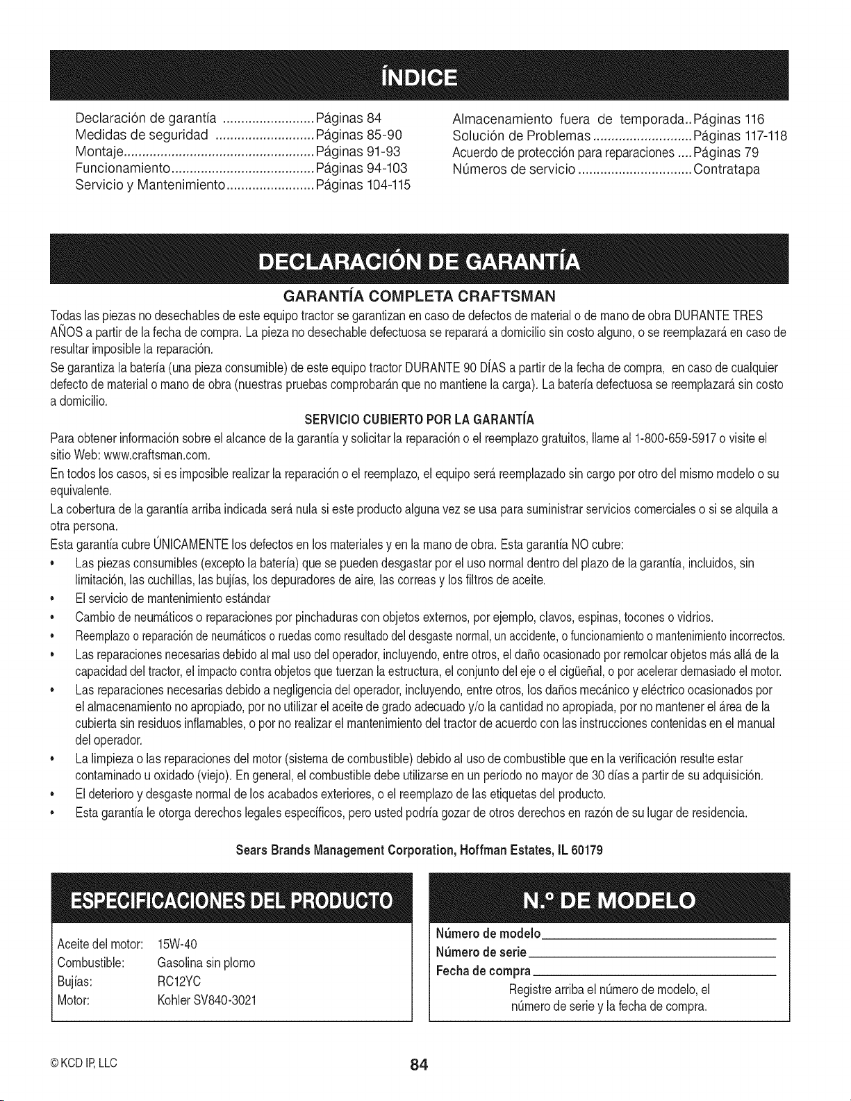
Declaraci6n de garantia ......................... Pa.ginas 84
Medidas de seguridad ........................... Pa.ginas 85-90
Montaje .................................................... Pa.ginas 91-93
Funcionamiento ....................................... Pa.ginas 94-103
Servicio y Mantenimiento ........................ Paginas 104-115
Almacenamiento fuera de temporada..Pa.ginas 116
Soluci6n de Problemas ........................... Pa.ginas 117-118
Acuerdo de protecci6n parareparaciones .... Pa.ginas79
NOmeros de servicio ............................... Contratapa
GARANTiA COMPLETA CRAFTSMAN
Todaslaspiezasnodesechablesdeesteequipotractorse garantizanencasodedefectosde materialo de manode obraDURANTETRES
ANOSa partirdela fechade compra.Lapiezanodesechabbdefectuosase reparar_,a domiciliosincostoalguno,o se reemplazar_,encasode
resultarimposiblela reparaci6n.
Segarantizalabateria(unapiezaconsumible)deesteequipotractorDURANTE90 DfASa partirde lafechadecompra, encasode cualquier
defectode materialo manode obra(nuestraspruebascomprobar_.nque nomantienela carga).Labateriadefectuosase reemplazar_,sincosto
a domicilio.
SERVICIOCUBIERTOPORLAGARANTiA
Paraobtenerinformaci6nsobreelalcancede lagarantiay solicitarla reparaci6no el reemplazogratuitos,llameal 1-800-659-5917o visiteel
sitioWeb:www.craftsman.com.
Entodoslos casos,si es imposibb realizarla reparaci6noel reemplazo,el equiposer_ reemplazadosincargo porotrodel mismomodeloo su
equivalente.
Lacoberturade lagarantiaarribaindicadaser_.nulasi esteproductoalgunavezse usa parasuministrarservicioscomerciabso si sealquilaa
otra persona.
EstagarantiacubreONICAMENTElosdefectosenlos materiabsyen la manode obra. EstagarantiaNOcubre:
• Las piezasconsumibles(exceptola bateria)que se puedendesgastarpor el usonormaldentrodel plazode la garanfia,incluidos,sin
limitaci6n,las cuchillas,lasbujfas,losdepuradoresde aire,las correasy los filtrosde aceite.
• El serviciode mantenimientoestandar
• Cambiode neum_.ticoso reparacionespor pinchadurascon objetosexternos,por ejemplo,clavos,espinas,toconeso vidrios.
• Reemplazoo reparaci6nde neum_.ticoso ruedascomoresultadodel desgastenormal,un accidente,o funcionamientoo mantenimientoincorrectos.
, Las reparacionesnecesariasdebidoal real usodel operador,incluyendo,entreotros,el da_oocasionadopot remolcarobjetosm_.sall_.de la
capacidaddel tractor,el impactocontraobjetosquetuerzanlaestructura,elconjuntodel eje o el cigLie_al,o pot acelerardemasiadoel motor.
• Las reparacionesnecesariasdebidoa negligenciadel operador,incluyendo,entreotros,los da_osmecanicoy el@tricoocasionadospor
el almacenamientonoapropiado,porno utilizarel aceitedegradoadecuadoy/o la cantidadno apropiada,por no mantenerel _rea de la
cubiertasin residuosinfiamabbs,o porno realizarel mantenimientodeltractorde acuerdocon las instruccionescontenidasenel manual
deloperador.
• La limpiezao las reparacionesdelmotor(sistemadecombustible)debidoal usode combustiblequeen la verificaci6nresulteestar
contaminadouoxidado(viejo).Engeneral,el combustibledebeutilizarseen un periodonomayorde30 diasa partirdesu adquisici6n.
• El deterioroy desgastenormalde losacabadosexteriores,o el reemplazodelas etiquetasdel producto.
• Esta garantiale otorgaderechoslegalesespecificos,perousted podriagozarde otros derechosen raz6nde su lugar de residencia.
Sears Brands Management Corporation, Hoffman Estates, IL 60179
Aceitedel motor: 15W-40
Combustible: Gasolinasin plomo
Bujias: RC12YC
Motor: KohlerSV840-3021
NSmerode rnodelo
NSmerode serie
Fechade compra
Registrearribael nOmerode modelo,el
nOmerodeseriey lafechade compra.
© KCD IP,LLC 84.
Lapresenciadeestesimboloindicaquesetratadeinstruccionesde
seguridadimportantesquesedebenrespetarparaevitarponerenriesgo
suseguridadpersonaly/osusbienesylaseguridadylosbienesdeotras
personas.Leaycumplatodaslasinstruccionesdeestemanualantesde
intentaroperarestam&quina.Sinorespetaestasinstruccionessepueden
producirlesionespersonales.Cuandoveaestesimbolo,iTENGAEN
CUENTALAADVERTENCIA!
PROPOSICION 65 DE CALiFORNiA
Elescapedelmotor,algunosdeloselementosdelmismoy algunoscomponentesdel
vehiculocontieneno liberansustanciasquimicasqueseg@elestadodeCalifornia
puedenproducircancer,defectosdenacimientouotrosproblemasreproductivos.
Losbomesdelabateriay losaccesoriosafinescontienenplomoycompuestosde
plomo,sustanciasquimicasquesegQnIoestablecidoperel EstadodeCalifornia
causancancery daSosenelsistemareproductivo.Laveselasmanosdespuesde
estarencontactoconestoscomponentes.
Estam&quinaest&diseSadaparaserutilizadarespetandolasnormas
de seguridadcontenidasen este manual.AI igual quecon cualquiertipo
de equipomotorizado,un descuidoo error por partedel operadorpuede
producir lesionesgraves.Esta m_quinaes capaz de amputardedos,
manos y piesy dearrojarresiduos.Deno respetarlas instruccionesde
seguridadsiguientesse puedenproducir lesionesgraveso la muerte.
Su Responsabilidad--Lirnite el uso de esta rn&quina rnotorizada
a personas que sepan leer, que cornprendan y respeten las
advertencias e instrucciones que aparecen en este manual yen la
rn_.quina.
iGUARDE ESTAS INSTRUCClONES!
FUNCIONAIVIIENTO GENERAL
• Lea,entienday cumplatodas las instruccionesincluidasen lam_quina
yen el(los) manual(es)antesde intentarrealizarel montajede la unidad
y de utilizarla.Guardeeste manualen un lugar seguroparaconsultas
futurasy peri6dicas,asi como parasolicitar repuestos.
• Familiaricesecontodos loscontrolesy con el uso adecuadode los
mismos.Sepac6mo detenerla m_quinay desengancharlos controles
r@idamente.
• No permitanuncaque losniSosmenoresde 14 aSosutilicenesta
m_quina.Los niSosde 14aSosen adelantedebenleer y entenderlas
instruccionesde operaci6ny las normasde seguridadcontenidasen
estemanualyen la m_quinay debenset entrenadosy supervisadospot
un adulto.
• No permitanuncapermitaque personasadultas operenesta m_quina
sin recibirantes lainstrucci6napropiada.
• Paratratar deevitar elcontactocon las cuchillaso una lesi6npot algQn
objetoque seaarrojado,mantengaa losobservadores,a los ayudantes,
niSosy mascotasalejadosal menos25 metrosde la m_quinamientras
est&en funcionamiento.Detengala m_quinasi alguiense acerca.
• Inspeccioneminuciosamenteel &teadonde utilizar_elequipo.Retireto-
das las piedras,palos,cables, huesos,juguetesy otrosobjetos extraSos
que podrianserrecogidosy arrojadospor la acci6nde la(s) cuchilla(s).
Los objetosarrojadospor lam&quinapuedencausarlesionesgraves.
• Planifiqueel patr6ndecorte a seguir para evitardescargarel material
en caminos,veredas,dondehay observadores,etc. Eviteadem&s
descargarmaterialcontrauna paredu obstrucci6n,ya que estopodria
hacer queel materialdescargadorebotecontrael operador.
• Paraprotegerselosojos utilicesiempreanteojoso antiparrasde
seguridadmientrasoperala m&quinao mientrasle haceajusteso la
repara.Los objetosarrojadosque rebotanpuedencausar lesiones
ocularesgraves.
• Utilicezapatos de trabajoresistentes,de suelafuerte, asi como panta-
Ionesy camisasajustados.Las prendassueltaso lasalhajaspueden
quedaratrapadasen las piezasm6viles.Nuncaopere la m_quina
descalzoo con sandalias.
• Esteatentoa la cortadoray a la direcci6nde ladescargade los
aditamentosy no apuntea nadie.Nuncahagafuncionarla cortadora
de cespedsin queestenadecuadamentecolocados lacubiertade
descargao todo el colectorde recortesde cesped.
• No pongalas manoso los piescerca de laspiezasrotatoriaso debajo
de la plataformade corte. Elcontactocon la(s) cuchilla(s)puede
producirla amputaci6nde manosy pies.
• Unacubiertade descargafaltanteo daSadapuedeprovocarel contacto
con lacuchilla o lesionesporobjetosarrojados.
• Detengala(s) cuchilla(s)cuandoatraviesesenderos,sendaso caminos
de gravay cuandono estecortando el cesped.
• Vigile eltr_nsitovehicularcuandoeste operandocercade caminoso en
losencruces. Esta m_quinano debe utilizarseen lavia pL]blica.
• No opereesta m_quinabajolos efectosdel alcoholo de drogas.
• Corte el cespedsolamentecon luzde dia o conbuenaluz artificial.
• Nuncatransportepasajeros.
• Retrocedalentamente.Siempremire haciaabajoy haciaatr_santes
de retrocedery mientrasIo hace,para evitaraccidentespor manejar
marchaarras. Esteatentoyvigile el funcionamientodel sistemade
seguridadque corta la energiade lascuchillasal conducirmarchaatr&s.
Si no funcionacorrectamente,p6ngaseencontactocon undistribuidor
autorizadoparaque se inspeccioney repareel sistemade seguridad.
• Reduzcalavelocidad antesde dar la vuelta.Operela m&quinade forma
pareja.Eviteelfuncionamientoerr_tico y lavelocidadexcesiva.
• Desenganchela(s) cuchilla(s),coloqueel frenode mano,detengael
motory esperehastaque la(s) cuchilla(s)se detenga(n)pot completo
antesde retirarel colector de cesped,vaciar losrecortes,destaparel
canal, retirarrestosde cespedo desechos,o hacercualquierajuste.
• Nunca deje la rn_.quinaen funcionarniento sin vigilancia. Apague
siernpre las cuchillas, coloque las palancas de control de
transrnisi6n en neutral, coloque el freno de rnano, detenga el
motor y retire la Ilave antes de bajarse del vehiculo.
85
• Tengasumocuidadoal cargaro descargarla m_.quinaenun
remolqueo cami6n.Estaunidadnodebeconducirseen ascenso
odescensode rampas,porquepodriavolcary provocarlesiones
personalesgraves.La m_.quinase debe empujarmanualmente
en lasrampasparacargarlao descargarlacorrectamente.
El silenciadory elmotorse calientany puedencausarquemadu-
ras.No los toque.
Reviseel espaciolibreporencimadela cabezaantesde
conducirdebajodelas ramasbajasde _.rboles,cables,entradas
de puertas,etc.,en loscualeseloperadorpodriaatorarseo set
tiradofueradela m_.quina,Iocual podriaresultarenlesiones
graves.
• Desenganchetodos los embraguesde losaccesorios,coloqueel
frenodemanoen posici6n'on'y muevalas palancasdecontrol
detransmisi6nde ladoderechoy ladoizquierdototalmentehacia
afueraa la posici6nneutralantesdeintentararrancarel motor.
• La m_.quinaest,. dise_adapara cortarcesped residencialnormal,
con unaaltura nomayora 10".Nointentecortarpastodemasiado
crecidoy seco(porej.,pastura)ni pilasde hojassecas.Elpasto
y las hojassecaspuedenentrarencontactoconel escapedel
motory/o acumularseenla plataformade lacortadoradecesped,
convirti_ndoseen un peligrode incendio.
• Utilicesolamenteaccesoriosy aditamentosaprobadosparaesta
m_.quinaporel fabricantede la misma.Lea,comprenday siga
todaslasinstruccionesproporcionadascon los accesorioso
aditamentosaprobados.
• Losdatos estadisticosmuestranque losoperadoresde 60a_os
enadelanteest_.ninvolucradosen unalto porcentajedelesiones
relacionadascon tractorescortacesped.Estosoperadoresdeben
evaluarsu capacidadparaoperareltractorcortacespedenforma
suficientementeseguraparaprotegerseellos mismosy a los
dem_.scontralesionesgraves.
• Si se presentansituacionesqueno est_.nprevistasen este
manual,tengacuidadoy use elsentidocom[3n.Comuniquese
con lalineade ayudade Craftsmanal 1-800-659-5917para
solicitarasistencia.
FUNCIONAMIENTO EN PENDIENTES
Laspendientessonun factorimportanterelacionadocon accidentes
por derrapey vuelcosquepuedenproducirlesionesgravese incluso
la muerte.Laoperaci6nen pendienterequieremayorprecauci6n.
Si no puederetrocederenla pendienteo si nose sienteseguro,no
realiceningunaoperaci6nde corte.
Parasu seguridad,useel indicadorde pendientesque seincluye
comopartedeeste manualparamedirlapendienteantesde operarla
m_.quinaen unazonainclinada.Si la pendientees mayorde 15grados
segQnel medidor,noopereestam_.quinaenese sector,puespodria
causarlesionesgraves.
HagaIo siguiente:
• Corte de formatransversala la pendiente,nohaciaarribani
haciaabajo.Tengamuchocuidadoalcambiardedirecci6nen
una pendiente.
• Est_atentoa los hoyos,surcos,baches,rocasu otros objetos
ocultos.Elterrenodesniveladopuede voltearla m_.quina.El
c_spedalto puedeocultarobst_.culos.
• Vayaa bajavelocidad.Elija una velocidadIo suficientemente
baja,de modoqueno tengaquedetenersemientrasest,.en la
pendiente.Evitearrancarodetenerseen unapendiente.Silos
neum_.ticosno puedenmantenerla tracci6n,desenganchelas
cuchillasy bajelentamentey con cuidadopor lapendiente.
• Siga las recomendacionesdel fabricantepara los pesoso contra-
pesosdelas ruedas,paramejorarla estabilidaddela m_.quina.
• Tengaespecialcuidadocon los colectoresde c_sped u otros
aditamentos.Losmismospuedenmodificarla estabilidaddela
m_.quina.
• Hagaque todos los movimientosen las pendientesseanlentosy
graduales.Nocambierepentinamentelavelocidadnila direcci6n.
Laaceleraci6no la reducci6nrepentinade velocidadpueden
hacerqueel frentede la m_.quinase levantey d_ unavoltereta
haciaatr_.s,Io quepodriaproducirlesionesgraves.
No hagaIo siguiente:
• Nogire en pendientea menosque sea necesario;si Io hace,gire
lentamentecuestaarribay tengasumocuidadoalgirar.
• Nocorte el cespedcercade barrancas,zanjaso terraplenes.La
cortadoradec_spedpuedevolcarserepentinamentesi una de
las ruedasest,.sobreel hordedeun acantiladoo unazanjao si
un hordese desmorona.
• Nointenteestabilizarla m_.quinaponiendoel pie en el suelo.
• Noutilice colectorde c_speden pendientesempinadas.
• Nocorte el cespedmojado.La menortracci6npodriacausar
derrapes.
• No remolquecargaspesadasdetr_.sde losaditamentos(carrito
de basuracargado,rodilloparac_sped,etc.)en pendientes
mayoresde5 grados.Cuandose desplazapendienteabajo,el
pesoadicionaltiendea empujarel tractorcortacespedy puede
hacerque sepierdaelcontroldel mismo(porejemplo,el tractor
cortac_spedse puedeacelerar,se reducela capacidadpara
frenary maniobrar,los accesoriospuedenplegarsecomoun
cortaplumasy hacerqueel tractorvuelque).
86
N QOS
Pueden ocurrir accidentes tr_.gicos si el operador no est,. atento a la
presencia de ni_os. Por Io general, los ni_os se sienten atraidos por
este tipo de rn_.quinasy su funcionarniento. No entienden los riesgos
ni los peligros. Nunca suponga que los ni_os perrnanecer_.n en el
lugar donde los vio por Oltirnavez.
• Mantenga a los ni_os fuera del Area de trabajo y bajo estricta
vigilancia de un adulto responsable adern_.s del propio opera-
dot.
Est_ alerta y apague la rn_.quinasi un ni_o ingresa al _.rea.
Para evitar accidentes al retroceder, siernpre mire hacia atr_.s y
hacia abajo para ver si hay ni_os.
• Nunca transporte ni_os, ni siquiera con la(s) cuchilla(s)
apagada(s). Podrian caerse y resultar severarnente lesionados o
interferir con la operaci6n segura de la rn_.quina.
Tenga extrerna precauci6n cuando se aproxirne a esquinas
ciegas, portales, arbustos, _.rboles u otros objetos que puedan
irnpedirle vet a un ni_o que se cruce en el recorrido de la
rn_.quina.
Mantenga a los ni_os alejados de los rnotores en rnarcha o
calientes. Pueden sufrir quernaduras producidas por el silencia-
dor caliente.
Retire la Ilave cuando deje la rn_.quinasin vigilancia, para irnpedir
que una persona sin autorizaci6n la rnaneje.
No perrnita nunca que los ni_os rnenores de 14 a_os utilicen esta
rn_.quina. Los ni_os de 14 a_os en adelante deben leer y entender las
instrucciones de operaci6n y las norrnas de seguridad contenidas en
este manual yen la rn_.quinay deben ser entrenados y supervisados
por un adulto.
REIVIOLQUE
• Rernolque _nicarnente con una rn_.quinaque cuente con un
enganche diseSado para rernolcar. No acople equipo rernolcado
excepto en el punto de enganche.
• Siga las recornendaciones del fabricante en Io que respecta a
los lirnites de peso de los equipos a rernolcar y al rernolque en
pendientes.
• Nunca perrnita la presencia de niSos u otras personas dentro o
sobre el equipo rernolcado.
• En las pendientes, el peso del equipo rernolcado puede causar
perdida de tracci6n y la p_rdida de control de la rn_.quina.
• Despl_.ceselentarnente y deje distancia adicional para frenado.
• No carnbie a transrnisi6n neutral para descender.
SERVIClO
Manejo seguro de la gasolina
Paraevitarlesionespersonaleso da_os materialessea sumamente
cuidadosoal manipularla gasolina.La gasolinaes sumamenteinflamabley
sus vaporespuedencausarexplosiones.Se puedenproducir lesionesgraves
si se derramagasolinasobresu cuerpo o sobre la ropa,yaque la mismase
puedeencender.L&veselapiel y c_mbiesede ropade inmediato.
,, Utilices61olosrecipientespara gasolinaautorizados.
,, Apaguetodos loscigarrillos,cigarros,pipasy otrasfuentes de com-
busti6n.
,, Nuncacarguecombustibleen la m_quinaen un espaciocerrado.
,, Nuncasaque latapa del combustibleniagreguecombustiblemientras
el motorest&calienteo en marcha.Dejeque el motorse enfriepot Io
menosdos minutosantesde volvera cargarcombustible.
,, NuncaIleneenexcesoel dep6sitode combustible.Lleneel tanqueno
m&sde V2pulgadapor debajode la basedel cuellodel tap6n de carga,
paradejar espaciopara la expansi6ndel combustible.
,, Vuelvaa colocar latapa del combustibley ajL]stelabien.
,, Limpieel combustiblequese hayaderramadosobre el motory el equipo.
Trasladela m_quinaa otrazona.Espere5 minutosantesde encenderel
motor.
,, Parareducirel riesgo de incendio,mantengalam_quinalimpia de
pasto,hojas y sin acumulaci6nde otrosresiduos.Limpielosderrames
de aceiteo combustibley saquetodos los residuosembebidosen
combustible.
,, Nuncaguarde lam_quinao los recipientesde combustible,ni cargue
combustibleenun espaciocerradodondehayafuego,chispaso luz
piloto,por ejemplo,de calentadoresde agua, calefactoresde ambientes,
hornos,secadoresde ropa u otrosaparatosa gas.
,, Dejequela m_quinase enfrie pot Io menoscinco minutosantesde
guardarla.
,, Evitela descargaest_tica
,, NuncaIlenelos contenedoresen el interiorde un vehiculoo cami6n
o caja de remolquecon recubrimientopl_stico.Coloque siemprelos
contenedoresen el piso y lejosdel vehiculoantesde Ilenarlos.
,, Cuandosea factible, retireel equipoa gasolinadel cami6n o remolquey
realicelacarga de combustiblecon el equipoen el suelo.Siesto no es
posible,Ileneel equipo en unremolquecon un recipienteport_til,en vez
de hacerlocon unaboquilladispensadorade gasolina.
,, Mantengala boquilladeIlenadoen contactocon el hordedel dep6sito
de combustibleo con laaberturadel recipienteen todo momento,hasta
terminarla carga.No utiliceundispositivode boquillade apertura/cierre.
Servicio general
,, Nuncaenciendael motoren espacioscerradoso en unazonacon poca
ventilaci6n.Elescape del motorcontienemon6xidode carbono,un gas
inodoroy letal.
,, Antesde limpiar,repararo inspeccionarla m_quina,compruebeque
la(s) cuchilla(s)y todaslas partesen movimientose hayandetenido.
Desconecteel cablede labujia y p6ngalohaciendomasacontrael
motorparaevitar quese enciendaaccidentalmente.
,, Reviseperi6dicamentepara asegurarseque lascuchillasse detengan
porcompletoen aproximadamentecinco (5) segundosdespuesde
accionarel controlde desenganchede lasmismas.Si lascuchillasno
se detienendentrode estelapso,su m_quinadebe set reparadapot un
profesionalde Sears u otro serviciocalificado.
87
• Controle peri6dicarnente el funcionarniento del sisterna de
bloqueo de seguridad, corno se describe rn_.sadelante en este
manual, Si el sisterna de bloqueo de seguridad no funciona
correctarnente, solicite el servJciode rnantenirniento profesional
de Sears u otro distribuidor calificado,
,, Reviselospernosde montajede la(s) cuchilla(s) y del motora
intervalosfrecuentespara verificarque estenbien apretados.Adem_s,
inspeccionevisualmentela(s) cuchilla(s) en buscadeda_os (por
ejemplo,desgasteexcesivo,abolladuras,rajaduras).Reemplacela(s)
cuchilla(s) Onicamentecon lascuchillasde fabricantesde equipo
original(O.E.M.)que se enumeranen estemanual.Eluso de piezasque
no cumplencon lasespecificacionesdel equipooriginalpuederesultar
en rendimientoinadecuadoy puedeponeren peligrola seguridad.
• Lascuchillasde lascortadorasde cesped sonmuyafiladas.Envuelva
la cuchillao use guantesy extremelas precaucionescuandoefectOe
mantenimiento.
• Mantengatodos lospernos,tuercasytornillos bienajustadospara
asegurarsede que lam_quinase encuentraen condicionessegurasde
funcionamiento.
• Nuncamodifiqueel sistemade bloqueode seguridadniotros
mecanismosde seguridad.Controleperi6dicamenteque funcionen
correctamente.
• Despuesde golpearconalgQnobjeto extra_o,detengael motor,
desconecteel cablede la bujia yconecteel motora masa. Inspeccione
minuciosamentela m_quinapara vet si est_da6ada. Repareel da6o
antesde arrancary utilizarla m_quina.
• Nuncatrate dehacerajusteso reparacionesa la m_quinamientrasel
motorest_en marcha.
• Loscomponentesdel colectordecespedy la cubiertadedescarga,
est_nsujetosa desgastey da_os quepodrian dejarexpuestaspartes
m6vileso permitirque se arrojenobjetos.Paraprotegersu seguridad,
verifiquefrecuentementetodos loscomponentesy reempl_celos
inmediatamentes61oconpiezasde losfabricantesde equipooriginal
(O.E.M.)que seenumeranen estemanual.Eluso de piezasque no
cumplencon lasespecificacionesdel equipooriginal puederesultaren
rendimientoinadecuadoy puedeponeren peligrolaseguridad.
• Nocambie la configuraci6ndel reguladordel motor ni Iooperea
sobrevelocidad.Elreguladordel motorcontrolalavelocidad m_ximade
funcionamientosegurodel motor.
• Mantengao reemplacelasetiquetasde seguridady de instrucciones
segQnsea necesario.
• Observela reglamentaci6ny lasnormasrespectoa la eliminaci6n
correctade gasolina, aceite,etc. paraprotegerel medicambiente.
• SegQnlaComisi6nde Seguridadde Productosparael Consumidorde
los EstadosUnidos(CPSC)y la Agenciade Protecci6nAmbientalde los
EstadosUnidos(EPA),este productotieneunavida Qtilmedia de siete
(7) a_os6 270 horas de funcionamiento.AIfinalizar la vida Otilmedia
haga inspeccionaranualmenteestaunidadpor Sears u otrodistribuidor
calificadoparacerciorarsede quetodos los sistemasmec_nicosy de
seguridadfuncionancorrectamentey notienen excesivodesgaste.Si no
Io hace,puedenproducirseaccidentes,lesioneso la muerte.
NO MODIFIQUE EL MOTOR
Para evitar lesiones graves o la rnuerte, no rnodifique el motor de
ninguna rnanera. Si altera la configuraci6n del regulador, el motor se
puede desbocar y funcionar a velocidades que no son seguras. Nunca
carnbie la configuraci6n de f_brica del regulador del motor.
Aviso referido a ernisiones
Los rnotores que estan certificados y curnplen con las regulaciones
de ernisiones federales EPA y de California para SORE (Equipos
peque_os todo terreno) est_.ncertificados para funcionar con gasolina
sin plorno cornOny pueden incluir los siguientes sisternas de control
de ernisiones: Modificaci6n de motor (EM) y catalizador de tres vias
(TWO) si est_.n equipados con esos sisternas.
AMORTIGUADOR DE CHISPAS
Esta m&quinaest_ equipadacon unmotorde combusti6ninternay no
debeser utilizadaen un terrenoagrestecubiertopor bosque,malezaso
hierba,ni cercadel mismo,excepto queel sistemade escapedel motor
esteequipadocon un amortiguadorde chispas quecumpla con las leyes
localeso estatalescorrespondientes(encasode existir).
Si se utilizaunarnortiguadorde chispasel operadorIo debernantener
en condicionesde usoadecuadas.Enel Estadode Californialas
rnedidasanteriorrnenternencionadassonexigidaspor Icy (Arficulo
4442del C6digode RecursosPOblicosde California).Esposible
queexistanleyessirnilaresenotrosestados.Lasleyesfederalesse
aplicanenterritoriosfederales.
Unsupresorde chispasparael silenciadorestadisponibleparasu
cornpraIlarnandoa SearParts& Repairat 1-800-469-4663.
88
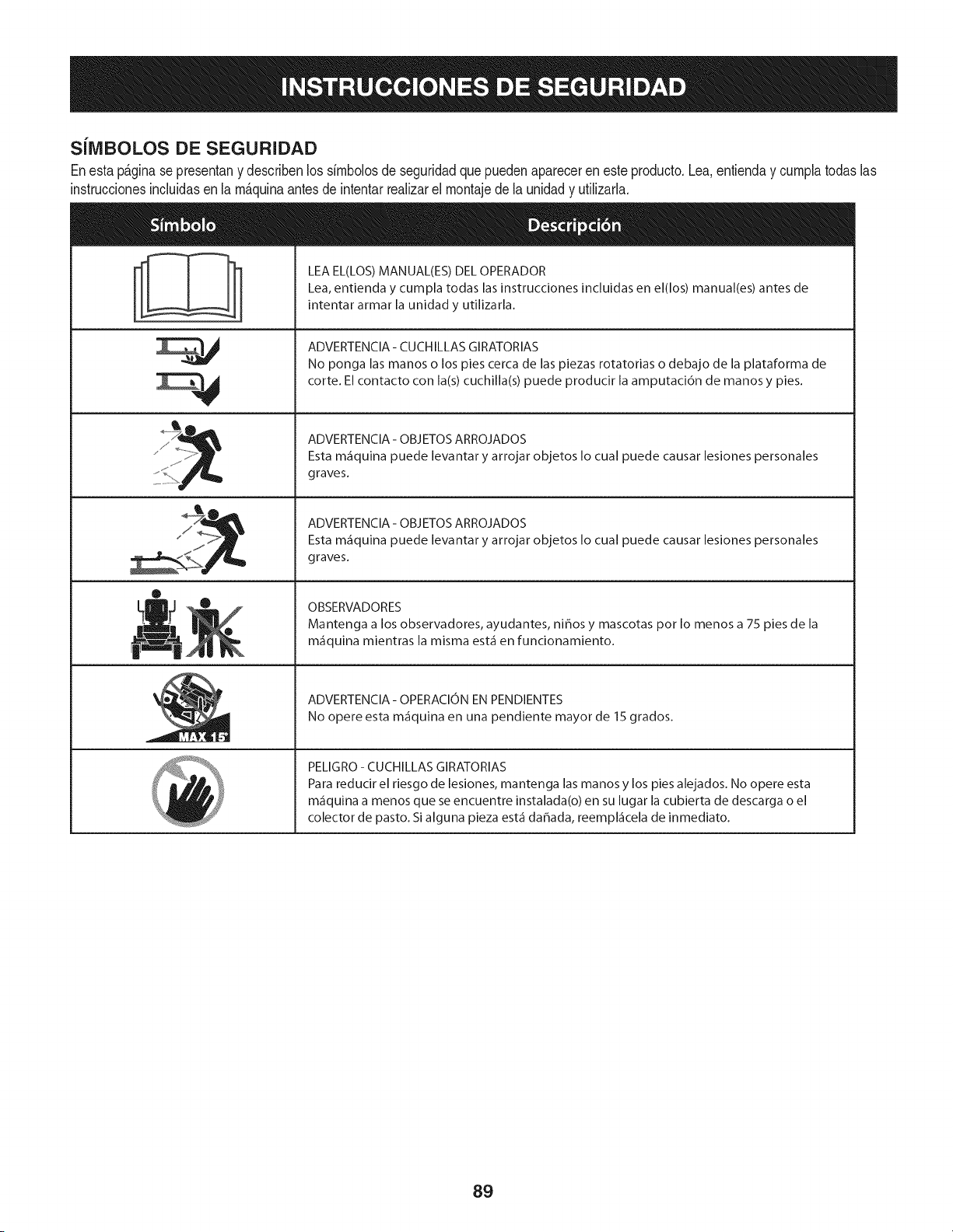
SiIVIBOLOS DE SEGURIDAD
Enestap&ginase presentany describenlos simbolosde seguridadquepuedenaparecerenesteproducto.Lea,entienday cumplatodaslas
instruccionesincluidasen la m_quinaantesdeintentarrealizarel montajedela unidady utilizarla.
s, ,// _
®
LEA EL(LOS) MANUAL(ES) DEL OPERADOR
Lea, entienda y cumpla todas las instrucciones incluidas en el(los) manual(es) antes de
intentar armar la unidad y utilizarla.
ADVERTENCIA- CUCHILLAS GIRATORIAS
No ponga las manos o los pies cerca de las piezas rotatorias o debajo de la plataforma de
corte. El contacto con la(s) cuchilla(s) puede producir la amputaci6n de manos y pies.
ADVERTENCIA- OBJETOS ARROJADOS
Esta m_iquina puede levantar y arrojar objetos Io cual puede causar lesiones personales
graves.
ADVERTENCIA- OBJETOS ARROJADOS
Esta m_iquina puede levantar y arrojar objetos Io cual puede causar lesiones personales
graves.
OBSERVADORES
Mantenga a los observadores, ayudantes, nihos y mascotas pot Io menos a 75 pies de la
m_iquina mientras la misma est,1 en funcionamiento.
ADVERTENClA- OPERAClON EN PENDIENTES
No opere esta m_iquina en una pendiente mayor de 15 grados.
PELIGRO - CUCHILLAS GIRATORIAS
Para reducir el riesgo de lesiones, mantenga las manos y los pies alejados. No opere esta
m_iquina a menos que se encuentre instalada(o) en su lugar la cubierta de descarga o el
colector de pasto. Si alguna pieza est,1 dahada, reempl_icela de inmediato.
89
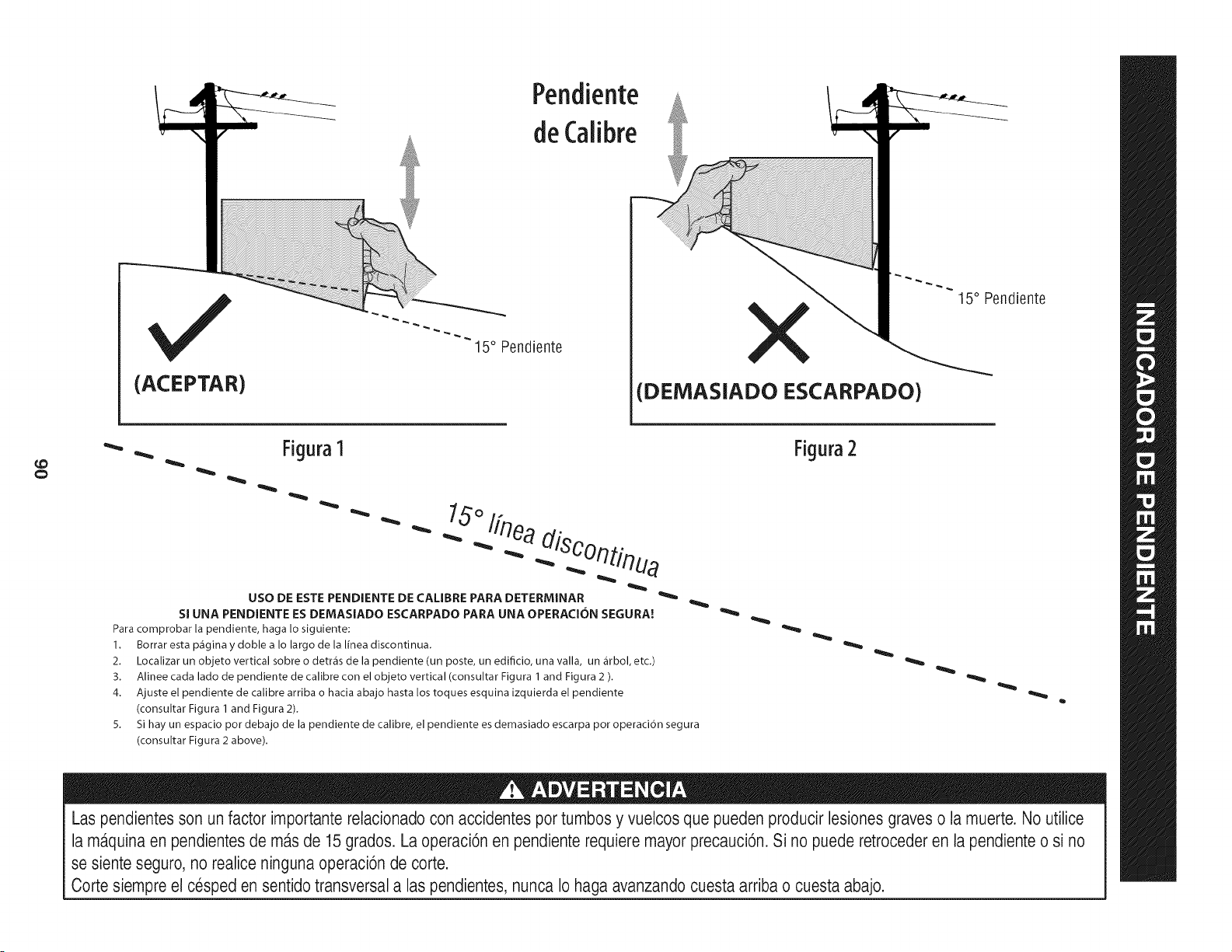
(ACEPTAR)
Pendiente
deCalibre
15° Pendiente
X
(DEMASIADO ESCARPADO)
15° Pendiente
¢O
"- .. Figura1
" " " •
" -- .. _/r/ua
USO DE ESTE PENDIENTE DE CALIBRE PARA DETERfvIINAR _'_
SI UNA PENDIENTE ES DEMASiADO ESCARPADO PARA UNA OPERACJON SEGURA!
Para comprobar la pendiente, haga Io siguiente:
1. Borrar esta p_igina y doble a Io largo de la linea discontinua.
2. Localizar un objeto vertical sobre o detr_is de la pendiente (un poste, un edificio, una valla, un _irbol, etc.)
3. Alinee cada lado de pendiente de calibre con el objeto vertical (consultar Figura 1 and Figura 2 ).
4. Ajuste el pendiente de calibre arriba o hacia abajo hasta los toques esquina izquierda el pendiente
(consultar Figura 1 and Figura 2).
5.
Si hay un espacio pot debajo de la pendiente de calibre, el pendiente es demasiado escarpa pot operacion segura
(consultar Figura 2 above).
Figura2
Las pendientesson un factor importante relacionado con accidentes por tumbos y vuelcos que pueden producir lesiones graveso la muerte. No utilice
la maquina en pendientesde mas de 15 grados. La operaci6nen pendiente requiere mayor precauci6n. Si no puede retroceder en la pendiente o si no
se siente seguro, no realice ninguna operaci6n de corte.
Oortesiempre el cesped en sentido transversala las pendientes, nunca Io haga avanzando cuesta arriba o cuesta abajo.
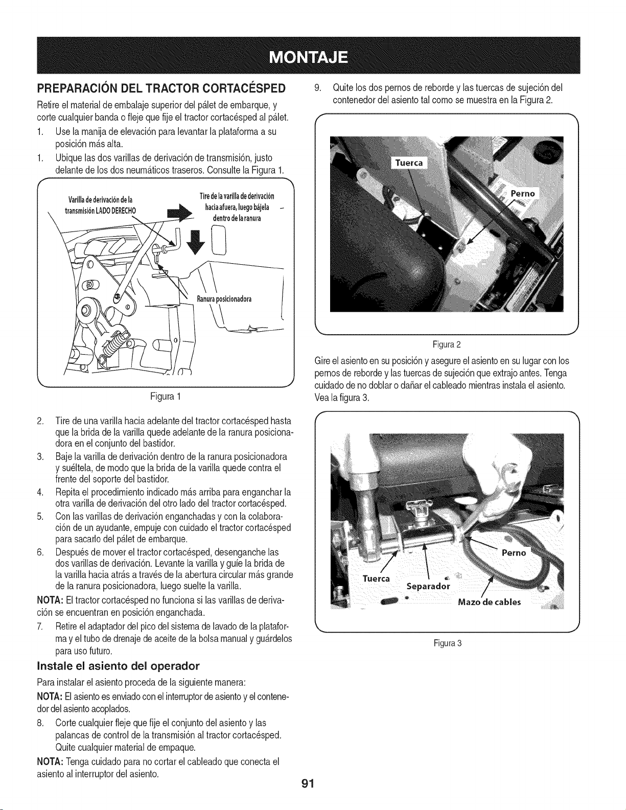
PREPARACIONDELTRACTORCORTACl_-SPED
Retireel materialde ernbalajesuperiordelp&letde ernbarque,y
cortecualquierbandao fiejequefije el tractorcortac_spedal p&let.
1. Use la rnanijade elevaci6npara levantarla plataforrnaa su
posici6nrn&salta.
1. Ubiquelasdos varillasde derivaci6nde transrnisi6n,justo
delantede los dosneurn&ticostraseros.Consultela Figura1.
Varilladederivaci6ndela
transrnisi6nLAD0DERECH0
Tiredelavarilladederivaci6n
haciaafuera,luegob&jela
dentrodelaranura
Ranuraposidonadora
Figura1
2. Tirede una varillahaciaadelantedel tractorcortac_spedhasta
quela bridade la varillaquedeadelantede la ranuraposiciona-
doraenel conjuntodel bastidor.
3. Baje la varillade derivaci6ndentrode la ranuraposicionadora
y su_ltela,de rnodoquela bridade lavarillaquedecontrael
frentedelsoportedel bastidor.
4. Repitael procedirnientoindicadornasarribaparaengancharla
otravarilladederivaci6ndel otroladodel tractorcortac_sped.
5. Conlasvarillasde derivaci6nenganchadasy conlacolabora-
ci6nde unayudante,empujeconcuidadoeltractorcortacesped
parasacarlodelp&letde ernbarque.
6. Despu_sde moverel tractorcortacesped,desenganchelas
dosvarillasde derivaci6n.Levantelavarillay guie labridade
lavarillahaciaatr&sa travesde laaberturacircularrn&sgrande
de laranuraposicionadora,luegosueltelavarilla.
NOTA: Eltractorcortacespednofuncionasi las varillasdederiva-
ci6n seencuentranen posici6nenganchada.
7. Retireel adaptadordel picodel sistemadelavadodelaplatafor-
rnay el tubodedrenajedeaceitede labolsamanualy gu&rdelos
parausofuturo.
Instale el asiento del operador
Parainstalarel asientoprocedade lasiguienternanera:
NOTA:Elasientoesenviadoconelinterruptordeasientoy elcontene-
dotdelasientoacoplados.
8. Cortecualquierfleje que fije el conjuntodel asientoy las
palancasde controlde latransrnisi6naltractorcortac_sped.
Quitecualquiermaterialde ernpaque.
NOTA:Tengacuidadoparanocortarel cableadoqueconectael
asientoalinterruptordelasiento.
9. Quite losdos pernosde rebordey las tuercasde sujeci6ndel
contenedordelasientotal cornose rnuestraenla Figura2.
Figura2
Gireel asientoensu posici6ny asegureel asientoen su lugarcon los
pernosde rebordey lastuercasde sujeci6nqueextrajoantes.Tenga
cuidadodenodoblarodaSarel cableadornientrasinstalael asiento.
Vealafigura3.
Figura 3
91
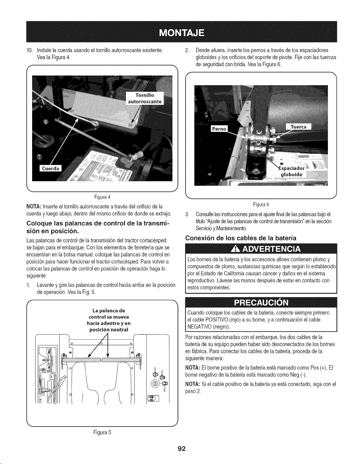
10, Instalelacuerdausandoel tornilloautorroscanteexistente.
Vea la Figura4.
Figura4
NOTA:Inserteeltornilloautorroscanteatravesdelorificiodela
cuerday luegoabajo,dentrodelrnisrnoorificiodedondese extrajo.
Coloque las palancas de control de la transmi-
si6n en posici6n.
Las palancasdecontroldela transrnisi6ndel tractorcortacesped
se bajanparael ernbarque.Conlos elernentosdeferreteriaquese
encuentranen la bolsamanual,coloquelas palancasdecontrolen
posici6nparahacerfuncionareltractorcortacesped.Paravolvera
colocarlas palancasde controlen posici6ndeoperaci6nhagaIo
siguiente:
1. Levantey gire las palancasdecontrolhaciaarribaen laposici6n
deoperaci6n.Veala Fig.5.
La palanca de
¢ontro_ se ITlueve
haciaadentro y en
posici6nneutral
o
>
Desdeafuera,insertelos pernosa travesde los espaciadores
globoidesy losorificiosdel soportede pivote.Fijecon lastuercas
de seguridadcon brida.Veala Figura6.
Figura6
3. Consultelasinstruccionesparaelajustefinaldelaspalancasbajoel
titulo"Ajustedelaspalancasdecontroldetransrnisi6n"enlasecci6n
Servicioy Mantenirniento.
Conexi6n de los cables de la bateria
Losbornesde la bateriay losaccesoriosalines contienenplornoy
cornpuestosde plorno,sustanciasquirnicasquesegQnIo establecido
porel Estadode Californiacausancancery daSosenel sisterna
reproductivo.L_.veselas rnanosdespu_sde estaren contactocon
estoscornponentes.
Cuandocoloquelos cablesdela bateria,conectesiernpreprirnero
el cablePOSlTIVO(rojo)asu borne,y a continuaci6nel cable
NEGATIVO(negro).
Porrazonesrelacionadascon el ernbarque,los dos cablesde la
bateriade suequipopuedenhabersidodesconectadosde los bornes
en f_.brica.Paraconectarlos cablesde la bateria,procedadela
siguienternanera:
NOTA:Elbornepositivode labateriaest,.rnarcadocornoPos(+). El
bornenegativode la bateriaest,.rnarcadocornoNeg (-).
NOTA:Siel cablepositivode la bateriaya est,.conectado,sigacon el
paso2.
k.
Figura5
J
92
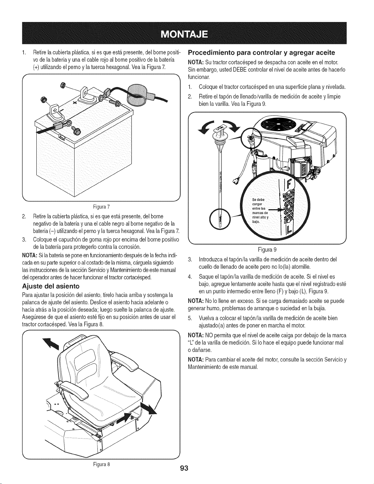
Retirelacubiertapl&sfica,si esqueest&presente,del bornepositi-
vode labateriay unael cablerojoal borneposifivode labateria
(+)utilizandoel pernoy la tuercahexagonal.VealaFigura7.
7
J
J
J
_'_'_-_._ ._. //--jl'j
Figura7
2. Retire[acubiertapl_.stica,si esqueest,. presente,del borne
negativode [abateriay unael cablenegroal bornenegativode [a
bateriai-_ utiiizandoel pernoy [atuercahexagonal.Vea[a Figura7.
3. Coloqueel capuch6nde gorna rojo por encirnadel borne positivo
de [abateriaparaprotegerlocontra[a corrosi6n.
NOTA:Si[abateriase poneenfuncionarnientodespu_sde [afechaindi-
cadaensu partesuperioroalcostadode[arnisrna,c_.rguelasiguiendo
[asinstruccionesde[asecci6nServicioy Mantenirnientodeestemanual
deloperadorantesdehacerfuncionareltractorcortacesped.
Ajuste del asiento
Paraajustarlaposici6ndelasiento,tirelo haciaarribay sostengala
palancadeajustedelasiento.Desliceelasientohaciaadelanteo
haciaatr_.sa la posici6ndeseada;luegosueltela palancade ajuste.
AsegQresedequeel asientoest_fijo en su posici6nantesde usarel
tractorcortacesped.Veala Figura8.
Procedimiento para controlar y agregar aceite
NOTA: Sutractorcortacespedse despachacon aceiteen el motor.
Sinembargo,ustedDEBEcontrolarel niveldeaceiteantesde hacerlo
funcionar.
1. Coloqueel tractorcortacespeden unasuperficieplanay nivelada.
2. Retireel tap6nde Ilenado/varillade rnedici6nde aceitey lirnpie
bienla varilla.Veala Figura9.
J
Figura9
3. Introduzcael tap6n/lavarillade rnedici6nde aceitedentrodel
cuellode Ilenadodeaceiteperono Io(la)atornille.
4. Saqueel tap6n/la varillade rnedici6nde aceite.Si el niveles
bajo,agreguelentarnenteaceitehasta que el nivelregistradoest_
en unpuntointerrnedioentreIleno(F) y bajo(L), Figura9.
NOTA: NoIo Ileneenexceso.Sise cargadernasiadoaceitesepuede
generarhurno,problernasdearranqueo suciedaden la bujfa.
5. Vuelvaa colocarel tap6n/la varillade rnedici6nde aceitebien
ajustado(a)antesde ponerenrnarchael motor.
NOTA: NOperrnitaqueel niveldeaceitecaigapordebajode la rnarca
"L"dela varillade rnedici6n.Si Io haceel equipo puedefuncionarrnal
o daSarse.
NOTA: Paracarnbiarel aceitedelmotor,consultelasecci6nServicioy
Mantenirnientode este manual.
Figura8 93
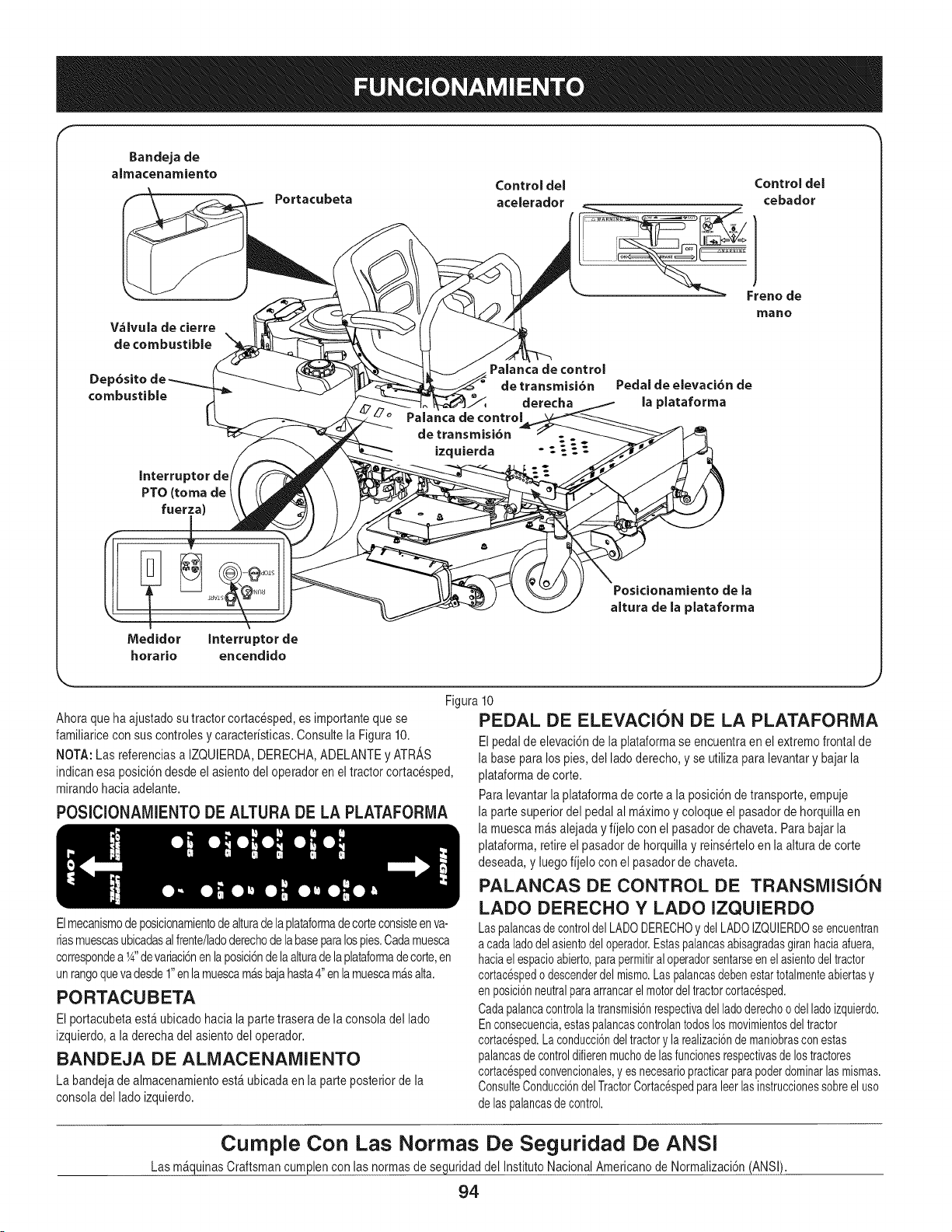
Bandeja de
almacenamiento
Control del Control del
Portacubeta acelerador cebador
V,_lvula de cierre
de combustible
Dep6sito
combustible
Interruptor de
PTO (toma de
fuerza
Medidor
horario
Interruptor de
encendido
Palanca de control
de transmisi6n
derecha
Palanca de control
de transmisi6n
izquierda - :_._
Freno de
mano
Pedal de elevacibn de
la plataforma
Posicionamiento de la
aJtura de la plataforma
Figura
Ahoraqueha ajustadosu tractorcortacesped,es importanteque se
familiaricecon sus controlesy caracteristicas.Consultela Figura 10.
NOTA:Las referenciasa IZQUIERDA,DERECHA,ADELANTEy ATRAS
indicanesa posici6ndesdeel asientodel operadoren eltractor cortacesped,
mirandohaciaadelante.
P0SICIONAMIENT0 DE ALTURA DE LA PLATAFORMA
Elmecanismode posicionamientodealturade laplataformadecorteconsisteenva-
riasmuescasubicadasalfrente/ladoderechode labaseparalospies.Cadamuesca
correspondea 1_,,devariaci6nenlaposici6nde laalturadelaplataformade corte,en
unrangoquevadesde1"enlamuescamasbajahasta4"en lamuescamasalta.
PORTACUBETA
El portacubetaest_ ubicadohaciala partetrasera de la consoladel lado
izquierdo,a laderechadel asientodel operador.
BANDEJA DE ALIVlACENAIVlIENTO
La bandejade almacenamientoest_ ubicadaen laparte posteriordela
consoladel ladoizquierdo.
J
lO
PEDAL DE ELEVACION DE LA PLATAFORIVlA
Elpedalde elevaci6nde la plataformase encuentraen elextremofrontal de
la base paralospies, del lado derecho,y se utiliza paralevantary bajarla
plataformade corte.
Paralevantarlaplataformade cortea la posici6nde transporte,empuje
la partesuperior del pedalal m_ximoy coloque el pasadorde horquillaen
la muescam&salejaday fijelo con el pasadordechaveta.Parabajar la
plataforma,retireel pasadorde horquillay reinserteloen la alturadecorte
deseada,y luegofijelo conel pasadorde chaveta.
PALANCAS DE CONTROL DE TRANSMISION
LADO DERECHO Y LADO IZQUIERDO
Laspalancasdecontroldel LADODERECHOy delLADOIZQUIERDOseencuentran
a cadaladodelasientodeloperador.Estaspalancasabisagradasgiranhaciaafuera,
haciaelespacioabierto,parapermitiraloperadorsentarseen elasientodeltractor
cortac_spedo descenderdelmismo.Laspalancasdebenestartotalmenteabiertasy
en posici6nneutralparaarrancarelmotordeltractorcortac_sped.
Cadapalancacontrolala transmisi6nrespectivadelladoderechoodelladoizquierdo.
Enconsecuencia,estaspalancascontrolantodoslosmovimientosdeltractor
cortac_sped.La conducci6ndeltractorylarealizaci6nde maniobrasconestas
palancasde controldifierenmuchodelasfuncionesrespectivasdelostractores
cortac_spedconvencionales,yes necesariopracticarparapoderdominarlasmismas.
ConsulteConducci6ndelTractorCortac_spedparaleerlasinstruccionessobreel uso
de laspalancasdecontrol.
Curnple Con Las Norrnas De Seguridad De ANSI
Las m_quinasCraftsmancumplencon las normasde seguridaddel InstitutoNacionalAmericanode Normalizaci6n(ANSi).
94
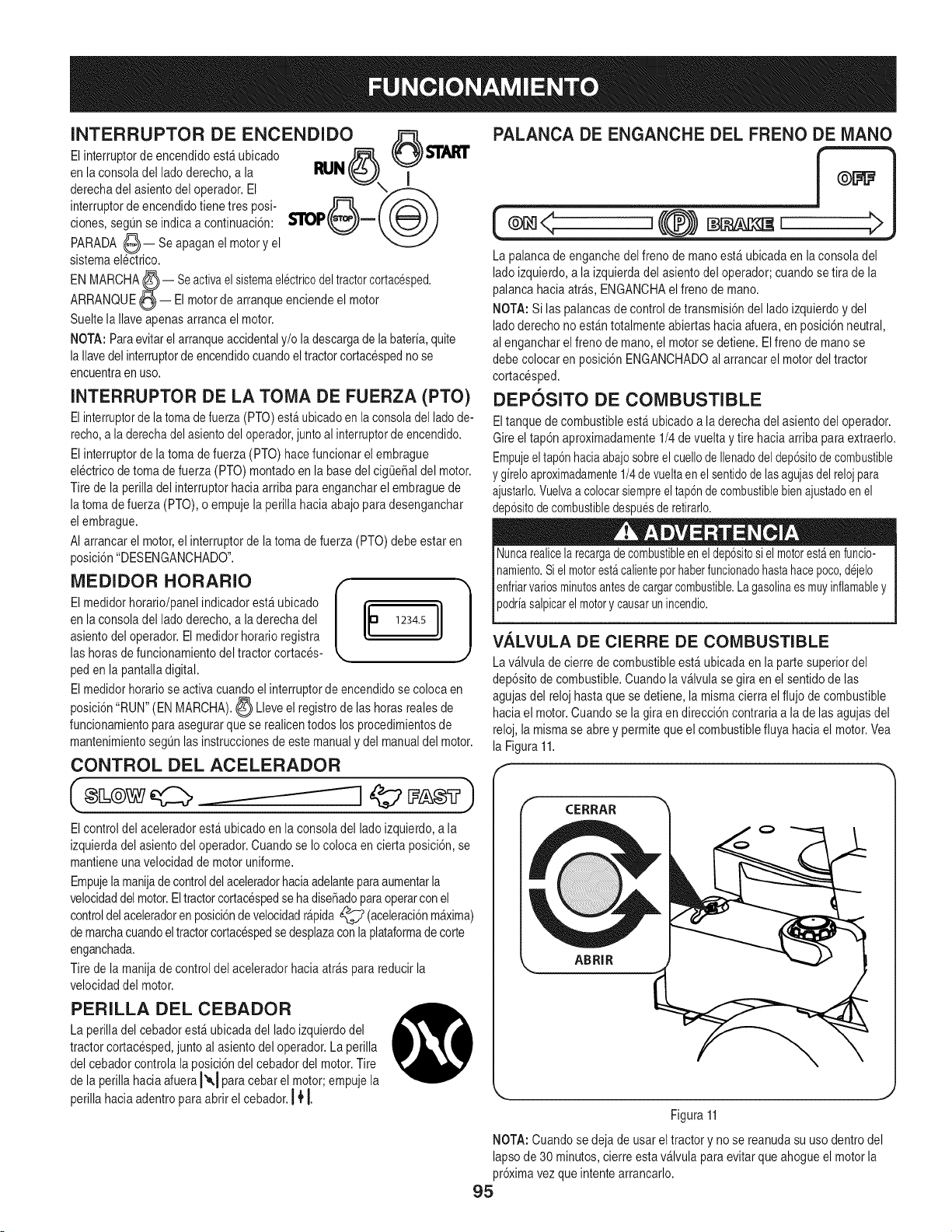
INTERRUPTOR DE ENCENDIDO ,_
El interruptorde encendidoest_ubicado _ ,v,(_r_) s'rAI_"
en la consolaeel lado derecho,a la m.,IN t_(_J T
derechadel asientodel operador.El ,,_
interruptorde encendidotienetres posi- _ /'_"_
clones,segQnse indica a continuaci6n: s'roll (,__j)- t _ )
PARADA (_)-- Se apaganel motory el
sistemaelectrico.
ENMARCHA_-- Seactivaelsistemael_ctricodeltractorcortac_sped.
ARRANQUE(_-- Elmotorde arranqueenciendeel motor
Sueltela Naveapenasarrancael motor.
NOTA:Paraevitarelarranqueaccidentaly/o ladescargade la bateria,quite
la Navedel interruptorde encendidocuandoeltractorcortacespednose
encuentraen uso.
asientodel operador.El medidorhoratioregistra
las horasdefuncionamientodeltractor cortaces-
peden la pantalladigital.
INTERRUPTOR DE LA TOMA DE FUERZA (PTO)
Elinterruptorde la tomadefuerza(PTO)esta ubicadoen laconsoladel ladode-
recho,a la derechadelasientodel operador,juntoal interruptorde encendido.
El interruptorde la tomade fuerza(PTO) hacefuncionar elembrague
electricode toma de fuerza (PTO)montadoen la basedel cigOe_aldel motor.
Tire de la perilladel interruptorhaciaarriba paraengancharel embraguede
latoma defuerza (PTO),o empujela perillahaciaabajo para desenganchar
el embrague.
AI arrancarel motor,el interruptorde latoma defuerza(PTO) debe estaren
posici6n"DESENGANCHADO".
o oooo,o oo,11
El medidorhoratio/panelindicadorestfi ubicado
en la consoladel lado derecho,a laderecha del 1234.5
El medidorhoratiose activa cuandoel interruptorde encendidose coloca en
posici6n"RUN" (EN MARCHA)._ Lleve el registrode lashoras realesde
funcionamientoparaasegurarque se realicentodos los procedimientosde
mantenimientosegQnlasinstruccionesde estemanualy del manualdel motor.
CONTROL DEL ACELERADOR
Elcontrol del aceleradorest_ ubicadoen la consoladel ladoizquierdo,a la
izquierdadel asientodel operador.Cuando se Iocolocaen cierta posici6n,se
mantieneunavelocidadde motoruniforme.
Empujelamanijade controldelaceleradorhaciaadelanteparaaumentarla
velocidaddelmotor.El tractorcortacespedseha dise_adoparaoperarconel
controldelaceleradoren posici6ndevelocidadr_pida_ (aceleraci6nm_xima)
de marchacuandoel tractorcortacespedse desplazacon laplataformade corte
enganchada.
Tire de la manijade control del aceleradorhacia arraspara reducirla
velocidaddel motor.
PERILLA DEL CEBADOR
La perilladel cebadorest_ ubicadadel lado izquierdodel
tractorcortacesped,junto al asientodel operador.Laperilla
del cebadorcontrolala posici6ndel cebadordel motor.Tire
de la perillahaciaafueraI'_1 paracebar el motor;empujela
perillahacia adentroparaabrir el cebador.14'[
PALANCA DE ENGANCHE DEL FRENO DE MANO
(®,< ,{@) >
La palancade enganchedelfreno de mano est_ubicada en la consoladel
ladoizquierdo,a la izquierdadel asientodel operador;cuandosetira de la
palancahaciaarras,ENGANCHAelfreno de mano.
NOTA:Si laspalancasde controlde transmisi6ndel lado izquierdoy del
ladoderechono est_ntotalmenteabiertas haciaafuera,enposici6nneutral,
al engancharelfreno demano,el motorse detiene.Elfrenode manose
debe colocaren posici6nENGANCHADOal arrancarel motordel tractor
cortacesped.
DEPOSITO DE COMBUSTIBLE
Eltanquede combustibleest_ ubicadoa laderecha del asientodel operador.
Gireel tap6n aproximadamente1/4 de vueltay tirehaciaarriba para extraerlo.
Empujeeltap6nhaciaabajosobreel cuellode Ilenadodeldep6sitodecombustible
y gireloaproximadamente1/4devueltaen elsentidode lasagujasdel relojpara
ajustarlo.Vuelvaa colocarsiempreel tap6ndecombustiblebienajustadoenel
dep6sitodecombustibledespuesde retirarlo.
Nuncarealicela recargadecombustibleeneldep6sitosi elmotorestaenfuncio-
namiento.Siel motorestacalienteporhaberfuncionadohastahacepoco,d_jelo
enfriarvariosminutesantesde cargarcombustible.Lagasolinaesmuyinflamabley
podra sap care motory causarun ncendo.
V,4.LVULA DE CIERRE DE COMBUSTIBLE
Lav_lvula de cierrede combustibleest_ubicada en la partesuperiordel
dep6sitode combustible.Cuandola v_lvula se giraen el sentidode las
agujasdel relojhastaque se detiene,lamismacierra el flujo decombustible
haciael motor.Cuandose la giraen direcci6ncontrariaa la delas agujasdel
reloj,la mismase abrey permiteque el combustiblefluya haciael motor.Vea
la Figura11.
CERRAR
ABRIR
, ,.,_
Figura11
NOTA:Cuandose deja de usarel tractory no se reanudasu uso dentrodel
lapsode 30minutos,cierreesta v_lvula para evitarque ahogueel motorla
pr6ximavezque intentearrancarlo.
95

PALANCA DE AJLISTE DEL ASIENTO (NO
SE MUESTRA)
La palanca de ajustedel asientoest_ ubicadadebajodel asiento,adelante
a la izquierda.La palancapermiteel ajustedel asientodel operador,hacia
adelanteo hacia atr_s. Consultela Secci6nServicioy Mantenimientopara
obtenerinstruccionessobre el ajustede la posici6ndel asiento.
VARILLAS DE DERIVACION DE LA TRANSMI-
SION (NO SE MUESTRAN)
Las varillasde derivaci6nde la transmisi6n(una para cadatransmisi6n,lado
derechoy ladoizquierdo)est_n ubicadasdebajode laplataformadel bastidor,
apenasadentrode cada ruedatrasera.Vea la Figura1 enla pagina91.
Cuandoest_nenganchadas,lasdos varillasabrenuna derivaci6ndentrode
lastransmisioneshidrost_ticas,Iocual permiteempujarel tractorcortacesped
de formamanuala Io largo dedistanciascortas. Consultela Secci6nMontaje
para obtenerinstruccionessobre el usodel dispositivode derivaci6n.
ravesa lastransmisiones,
DEPOSITO DE EXPANSION DE ACEITE DE
TRANSiVlISION (NO SE MUESTRA)
Eldep6sitode expansi6ndel aceite de transmisi6nest_ conectadopor
manguerasa losconjuntosde transmisi6nde ladoderechoy de lado
izquierdo,y est_ubicadodebajo de lacaja del asiento.La funci6ndel
dep6sitoes contenerlaexpansi6nnaturaldel aceitede transmisi6nque se
producea medidaque latransmisi6nse calientaduranteel funcionamientode
la m_quina.NOLLENEELDEPOSITO.
En condicionesoperativasnormales,no se debeagregaraceiteal dep6sito.
El nivelde aceite FRIOno debe superaraproximadamente1/4"(marca de
"Llenofrio") por encimade la basedel dep6sito.Veala Figura12.
/
Marca de aceite lieno frio
,. j
Figura12
NOTA:Antesdel funcionamientoinicialdel tractor cortacesped,el nivel
de aceitedel dep6sitopuedeestar levementepor encimadel m_ximo
debidoal aire que hayen laslineas de aceite. Elfuncionamientodel tractor
cortacespedcon el tiempo purgar_el airede laslineas y el nivelde aceitese
estabilizar_en el m_ximo.
Seguridad General
• RECIBALAS INSTRUCClONES- Lea estemanualdel operadoren
su totalidad.Aprendaa usaresta m_quinaCONSEGURIDAD.No se
arriesguea quedarexpuestoa LESlONESo a la MUERTE.Solamente
se debe permitiroperar estetractorcortacespeda quienesse hayan
familiarizadoa fondo con el usodel mismo.
, Antesde arrancarel motoro de empezara operar,familiaricesecon
los controles.El operadordebe estaren el asientodel operador.El
interruptorde latoma de fuerza(PTO)debe estaren posici6nDESEN-
GANCHADO,elfreno de mano ENGANCHADOy las palancasde control
de transmisi6ndel ladoderechoy del lado izquierdoen posici6nneutral.
• Mantengatodos los protectoresen su lugar.Guardedistanciadelas
partesm6viles.
• iNO SE PERMITETRASLADARPERSONASEN ELTRACTOR!
Mantengaatodas las personasy lasmascotasa unadistanciasegura
de la m_quina.Siempre mirehacia arrasy haciaabajo a amboslados
del tractor cortacespedantesde desplazarsemarchaatr_s y al hacerlo.
• NOoriente ladescargade la cortadorahaciala genre.Nocamineni
se detengadel lado de la descargade lacortadorasi el motorest_ en
marcha. DESENGANCHElatoma defuerza si otra personase acerca
mientrasest_usando el tractorcortacesped.
• EnIo posibleevitelas pendientes.Nuncaopereen pendientesmayores
de 15°.Las pendientescon mayorinclinaci6npresentancondiciones
de operaci6npeligrosas.Lostractorescortacespedpuedenvoltearse.
Siempreconduzcaeltractorde formatransversala la pendiente,
nunca haciaarribay haciaabajo. EnIo posibleevitegirarcuestaabajo;
arranqueabajoy trabajesindetenersehastala partem_salta. Ponga
especialcuidadoy conduzcalentamenteal girarcuestaabajo.Controle
la velocidady ladirecci6nde lam_quinade radiode girocero "principal-
mente"con elcontrolde velocidad/direccional(barra)del lado cuesta
debajode lam_quina,es decir,mantengalabarradel ladocuestaarriba
"esencialmente"en posici6nfija.
• Antesde dejarel asientodel operador:DESCONECTElatoma de
fuerza(PTO), mueva laspalancasde control de transmisi6ndel lado
derechoy del lado izquierdototalmentehaciaafueraen posici6n
neutral,Oenganche el frenode mano,apagueel motory quitela Ilave
de encendido.Antes derealizarel mantenimientoo la limpiezade la
m_quina,esperehastaque cesetotalmenteel movimiento.
• Cuandosedesplace hacia adelantecon eltractor cortacespedno deje
que las palancasde direcci6nvuelvana laposici6nneutralpor si solas.
Operelas palancasdecontrol de transmisi6nde forma parejay evite
realizarmovimientosbruscoscon lasmismasal arrancary detenerse.
Sujete bienlas palancasde control.
• Tengacuidadocuandouse el tractorcortacespedcercasenderoso
caminosde grava.Detengael movimientode las cuchillasy deltractor
cortacespedyesperea que pasen losvehiculosantes deoperar a Io
largo de laruta.
• No hagafuncionarel tractor cortacespedsin la plataformade corte.Si
se quita la plataformavariael equilibriodel tractor cortacespedy este
podriavoltearse.
• Eviteoperaren superficiesde tracci6ninestables;tengaextrema
precauci6nsi lasuperficiees resbaladiza.Retiresiemprelos residuosy
otros objetosdel _readondese va a cortarel cesped -los residuosy el
cesped sueltoreducenla tracci6n.
• Corte el cespedsolamentecon luzde dia o con buenaluz artificial.
• Observecon cuidadoparadetectar pozos,cabezalesaspersoresyotros
peligros ocultos.
• Evitedesplazarsedemasiadocerca de _rboles,arroyos,zanjas,
dep6sitosde arenay otrosobst_culos.
96
• Reduzcalavelocidadantesde girary detengasecompletamenteantes
de cualquiermaniobrade girocero.
, Si golpea un objetos61idomientrascorta elcesped, DESENGANCHEla
PTO,pongalas palancasde direcci6nen posici6nabierta,neutral,mueva
el aceleradora marchalentac_C_,coloqueelfrenode mano_, apague
el motory saquela Ilavedel interruptorde encendido.Inspeccionela
maquinaparaver si est#,daSada.Repareel daSo.Compruebequelas
cuchillasestenen buenascondicionesy quelos pernosde lascuchillas
estenbienapretadosantesde volvera poneren marchael motor.
• Nodetenga niestacioneeltractor cortacespedsobre materiales
combustiblestales comopasto u hojassecas,desechos,etc.
• Mantengala cortadorade cesped yespecialmenteel motory los
componenteshidr&ulicoslimpiosy sin grasa,pastoy hojaspara reducir
las posibilidadesde quese prendafuegoy permitirquese enfr[ende
formaadecuada.
• No Ileneel tanquede combustiblecon el motoren funcionamientoo si
el mismoest&caliente.Dejeenfriarel motorvarios minutosantesde la
recargade combustible.Aprieteeltap6n de combustiblecon firmeza.
ANTES DE USAR SU TRACTOR CORTACi_SPED
1. Antesde usarel tractorcortacesped,leaeste manualcon atenci6n
parafamiliarizarseconel funcionamientode todos los instrumentosy
controles.Elmanualse prepar6con lafinalidadde ayudarloa hacer
funcionary mantenerel tractorcortacespedeficientemente.
2. Lleneel dep6sitode combustibleQnicamentecon gasolinasin plomo
limpiay fresca,en un surtidorque indiqueunoctanajeigual a 87 o m_s.
Cuandoel dep6sitode combustibleIleguea la altura de unapulgadade
la partesuperiordel dep6sito,detengase.NOLLENEEL DEPOSITOEN
EXCESO.Debequedar espaciopara la expansi6nde la gasolina.
3. Reviseel niveldeaceitedel motor.Saquelavarilla de medici6nde
aceite,sequelay vuelvaa colocarla.S_quelanuevamentey lea elnivel
de aceite.Si est&por debajodel rangooperativo,agregueaceitepor el
tubode Ilenado,con un embudo,hastael niveldel rangooperativo.
4. Compruebesi lasruedasest&nadecuadamenteinfladas- 8-10 psi para
las ruedastraseras, 20-25para lasdelanteras.
NOTA: Los neum&ticosnuevosse inflan de formaexcesivaparaque el
rebordese asientebien en la Ilanta.
5. Verifiquequetodas lastuercas, pernosy tornillosesten bienapretados.
6. Compruebela tensi6nde lascorreasde transmisi6nde la plataforma
segQnlas instruccionesde lasecci6n Servicioy Mantenimiento.
7. Verifiqueque la plataformaestenivelada.Cuandose encuentra
correctamenteajustada,la plataformadel tractorcortacespeddebe
estar niveladade ladoa lado,y la partedelanterade la plataformadebe
estaraproximadamente1/4 de pulgadam&sbajaque la partetrasera
de la plataforma.Si hacefalta nivelarla plataforma,consultela secci6n
Servicioy Mantenimiento.
8. Lubriquetodos lospuntosde pivotequese enumeranen la secci6n
Servicioy Mantenimiento.
9. Ajusteel asiento para la mayorcomodidaddel operador,para una
adecuadavisibilidady para mantenerel controlcompletodel tractor
cortacesped.
SISTEMA DE BLOQUEO DE SEGURIDAD
• Estetractorcortacespedest_equipadocon un sistemade bloqueo
de seguridadparaprotecci6ndel operador.Si el sistemade bloqueo
funcionamal,no se debe hacerfuncionar eltractor cortacesped.Llame
al 1-800-659-5917paraprogramarel serviciode Piezasy Reparaciones
de Sears.
• El sistemade bloqueode seguridadevita que el motorintentearrancaro
arranquea menosquese muevanlas palancasdecontrol de transmi-
si6n del lado derecho y del ladoizquierdototalmentehaciaafueraen
posici6nneutral,se ENGANCHEel frenode manoy se DESENGAN-
CHEla tomade fuerza(PTO).
• Paraevitarun movimientobruscoal desengancharel frenode mano,
el sistemade bloqueode seguridadapagael motorsi las palancas
de controldetransmisi6ndel lado derechoy/o del ladoizquierdose
muevena una posici6ndistintade latotalmenteneutralcon elfrenode
manoenganchado.
• Si el operadorabandonasu asiento antesde colocarel frenode mano,
el sistemade bloqueode seguridadapagael motor.
• Si el operadorabandonasu asiento con latoma defuerza (PTO)
enganchada,se encuentreo no colocadoel frenode mano,el sistema
de bloqueode seguridadapagael motor.
NOTA:El interruptorde la tomade fuerza (PTO)se debe movera la posici6n
DESENGANCHADOpara volvera arrancarel motor.
• El sistemade bloqueode seguridadapagala tomade fuerza(PTO)y las
cuchillasde la cortadorasedetienensi lasdos palancasde control de
transmisi6nse muevena laposici6nde marchaarras.La PTOsevuelve
a engancharcuandounao lasdos palancasse muevennuevamentea
laposici6nneutralo a la de marchadirecta.
ENCENDIDO DEL MOTOR
Estetractor cortacespedest_equipadocon un sistemade bloqueo
de seguridaddiseSadoparaprotegeral operador.Noopere eltractor
cortacespedsi alguna partedel sistemade bloqueofuncionamal. Controle
peri6dicamentelasfuncionesdel sistemade bloqueopara verificarque
funcionenadecuadamente.
Porrazonesde seguridadpersonal,el operadordebeestar sentadoen el
asientodel tractor cortacespedal arrancarel motor.
1. Abra lav_lvula de pasode combustible.
2. Eloperadordebe estarsentadoen el asiento deltractor cortacesped
con lasdos palancasde controldetransmisi6nen posici6nneutral/de
arranque.
3. Coloqueel frenode mano_;_.
4. Verifiquequeel interruptorde latomadefuerza(PTO)se encuentreen
posici6nDESENGANCHADO(abajo).
5. Tire de la perilladel cebadorhaciaarriba,a laposici6n I'_,1CEBADOR.
NOTA:Siel motorest&caliente,tal vez no sea necesariocebarlo.
6. Muevaelcontrol del aceleradora la posici6nFAST_? (aceleradoral
m_ximo).
97
7. Gire la Ilavede encendidoen elsentido delas agujasdel reloja la
posici6nARRANQUE@ y su@elacuandoarranqueel motor;sin
embargo,no dearranquecontinuamentedurante m_s de 10segundos
porvez. Si el motorno arranca en este periodo,gire la Ilavea la posici6n
APAGADO_ y esperepor Io menos30 segundospara dejar quese
enfrie el motordearranquedel motor.Intentelode nuevodespuesde
esperar.Si despuesde unoscuantosintentosel motorno arranca,no
siga intentandoyaque con el cebadorcerrado se ahogar_el motory el
arranqueser_ m_sdificil aL]n.
8. Unavez queel motorse caliente,empujela perilladel cebadorhacia
abajoa la posici6nAPAGADO.
Arranque del motor en clima frio
AIarrancarel motora temperaturascercanaso inferioresal puntode conge-
lamiento,asegQresede que se use aceitede motorde viscosidadcorrectay
quela bateriatenga carga completa.Arranqueel motorde la siguienteforma:
1. AsegQresede que la bateriaseencuentreenbuen estado.Adem_s,una
bateriacalientetieneuna capacidadde arranquemuchomayorqueuna
bateriafria.
2. Usecombustiblefresco parauso invernal.La gasolina parauso invernal
tienemayorvolatilidada los efectosde mejorarel arranque.No use
gasolinaque le hayaquedadodelverano.
3. Siga las instruccionespreviasparaARRANCAREL MOTOR.
Llso de cables de puente para arrancar el motor
Las bateriascontienen_cidosulfQricoy producengasesexplosivos.
AsegQresede queel _reaeste bienventilada,use guantesy protectoresde
ojosy evitechispas o llamascerca de labateria.
Si lacarga de la bateriano es suficienteparadar arranque al motor,vuelva
a cargar labateria.Si no dispone de un cargadorde bateriay debe arrancar
eltractor cortacesped,puedeser necesariousaruna bateriade urgencia.
Conectela bateriadeurgenciade lasiguienteforma:
1. Conecteel extremode un cableal bornepositivode la bateriadeltractor
cortacespedque no funciona;luegoconecteel otro extremo deese
cableal bornepositivode la bateriadeurgencia.
2. Conecteun extremodel otro cable al borne negativode la bateriade
urgencia;luego conecteel otto extremode ese cableal bastidordel
tractorcortacespedque no funciona,a la mayor distanciaposiblede
la bateria.
3. Arranqueeltractor cortacespedque nofuncionasegQnlas instrucciones
de arranquenormalesindicadasm_sarriba; luegodesconectelos
cablesde puenteenordenexactamenteinversoal de laconexi6n.
4. Haga controlary repararel sistemaelectricodel tractorcortacespedIo
m_sprontoquefuere posible,paraeliminarla necesidadde usarcables
de puentepara arrancarlo.
Detenci6n del motor
1. Presioneel interruptorde la toma de fuerza(PTO) a la posici6n
DESENGANCHADO.
2. Mueva laspalancasde controlde transmisi6ndel ladoderechoy del
lado izquierdohacia afuera,a laposici6nneutral.
3. Coloqueelfreno de manoO.
4. Muevael controldel aceleradora distanciamediaentrelas posiciones
VELOCIDADLENTAc:CC_y VELOCIDADR_,PIDA._.
5. Gire laIlavede encendidoa la posici6nPARADA(_n)Yquitela Ilavedel
interruptorde encendido.
NOTA: Siemprequitela Ilavedel interruptorde encendidoparaevitar el arran-
que accidentalo la descargadela bateriasi elequipo quedasin supervisi6n.
PRACTIQUE EL MODO DE OPERACION CON
EL TRACTOR (USO INICIAL)
Operarun tractorcortacespedcon radiodegirocero noes Io mismoqueoperar
un tractorcortacespedconvencional.Comoun tractorcortacespedcon radio
de girocero es m_smaniobrable,es necesariopracticarla operaci6nde las
palancasde controlparaacostumbrarsea las mismas.
Recomendamosenf_ticamenteque encuentreun "_reade pr_ctica"de
superficierazonable,niveladayabierta, en la cual no hayaobstrucciones,
peatonesni mascotas.Debe practicarla operaci6ndel tractor cortacesped
durante30 minutospor Io menos.
Trasladeel tractorcortacespedcon cuidado- o hagaque un usuario
experimentadorealiceel traslado- al _reade pr_ctica.Cuandoeste
practicando,latoma de fuerza(PTO) nodebe estar enganchada.Mientras
practica,hagafuncionar eltractor cortacespeda aproximadamente1/2a 3/4
de aceleraci6ny a unavelocidad inferiora la m_ximatantoen marchadirecta
como en marchaatr_s.
Use equipode protecci6nparalos ojos, las manos,auditivo,paralos pies,
las piernas,la cabezay otras_reas del cuerposi es necesario- anteojosde
seguridad,guantes,taponespara oidos, botas,casco,etc.
Se necesitaprotecci6nauditivapara toda exposici6ndel operador que
superelas dos(2) horas.
Ejercitecuidadosamentelas maniobrascon el tractor cortacesped,usando
las instruccionesde lasecci6nsiguiente"Conducci6ndeltractor cortaces-
ped". Practiquehastaque se sientaconfiadode podermanejarel tractor
cortacespedcon seguridad.
98
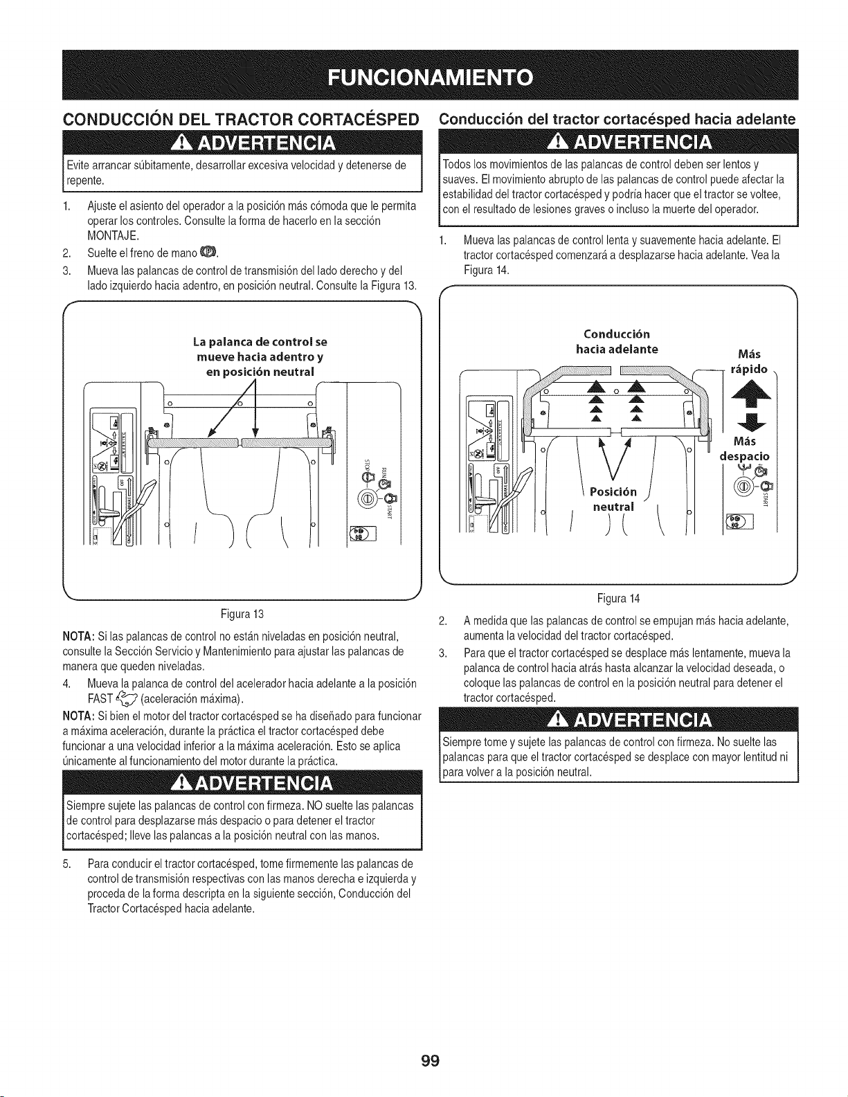
CONDUCCION DEL TRACTOR CORTACC:SPED
Evitearrancars0bitamente,desarrollarexcesivavelocidady detenersede
repente.
1. Ajusteel asiento del operadora la posici6nm&sc6modaquele permita
operarloscontroles.Consultelaformade hacerloen la secci6n
MONTAJE.
2. Suelteelfreno de manoO.
3. Muevalas palancasde controlde transmisi6ndel lado derechoy del
ladoizquierdohacia adentro,en posici6nneutral.Consultela Figura13.
La palanca de control se
mueve hacia adentro y
en posici6n neutral
Conduccion del tractor cortacesped hacia adelante
Todoslosmovimientosde laspalancasde controldebenser lentosy
suaves.Elmovimientoabruptode las palancasde control puedeafectarla
estabilidaddel tractor cortacespedy podrfahacer queel tractorse voltee,
con e resutado de es onesgraveso ncuso a muerte de operador.
1. Muevalaspalancasde control lentay suavementehacia adelante.El
tractor cortacespedcomenzar_a desplazarsehaciaadelante.Veala
Figura14.
t,.. .j
Figura 13
NOTA:Si las palancasde controlno est_n niveladasen posici6nneutral,
consultela Secci6nServicioy Mantenimientoparaajustarlas palancasde
maneraque quedenniveladas.
4. Muevala palancade controldel aceleradorhacia adelantea la posici6n
FAST_ (aceleraci6nm_xima).
NOTA:Si bienel motordel tractor cortacespedse ha diseSadoparafuncionar
a m&ximaaceleraci6n,durantela pr&cticaeltractor cortacespeddebe
funcionara unavelocidadinferiora la m&ximaaceleraci6n.Estose aplica
Onicamentealfuncionamientodel motordurantela pr_ctica.
Siempresujetelaspalancasde controlcon firmeza. NOsuelte laspalancas
de control para desplazarsem&sdespacioo para detenerel tractor
cortacesped;Ilevelaspalancas a la posici6nneutralcon lasmanos.
5,
Paraconducirel tractorcortacesped,tome firmementelas palancasde
controlde transmisi6nrespectivascon lasmanos derechae izquierday
procedade laforma descriptaen lasiguientesecci6n,Conducci6ndel
TractorCortacespedhaciaadelante.
2,
3.
Figura14
A medidaque laspalancasde controlse empujanm_shaciaadelante,
aumentalavelocidaddel tractor cortacesped.
Paraqueel tractor cortacespedse desplacem&slentamente,mueva la
palancade control haciaatr&shastaalcanzarla velocidaddeseada,o
coloquelas palancasdecontrol en la posici6nneutralpara detenerel
tractor cortacesped.
la posici6nneutral.
99
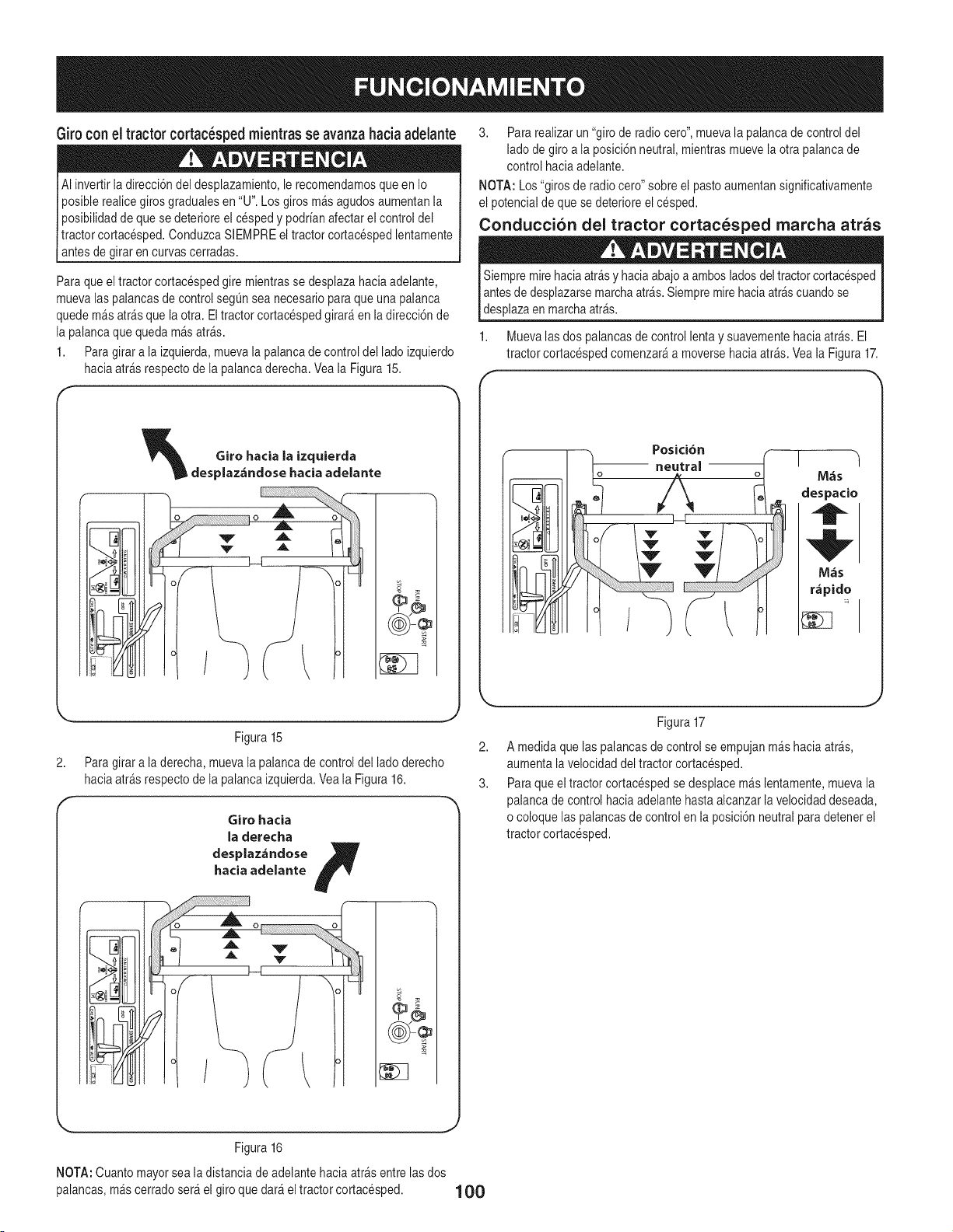
Giro con el tractor cortac_sped mientras se avanzahaciaadelante
AI invertirladirecci6n del desplazamiento,le recomendamosqueen Io
oosiblerealicegiros gradualesen "U". Losgiros m_sagudosaumentanla
_osibilidadde que se deterioreel cespedy podr[anafectarel controldel
Lractorcortacesped.ConduzcaSlEMPREel tractorcortacespedlentamente
antes de girar en curvascerradas.
Para queel tractorcortacespedgire mientrasse desplazahacia adelante,
muevalas palancasdecontrol segQnsea necesariopara que unapalanca
quedem_sarrasque la otra.El tractor cortacespedgirar_en ladirecci6n de
la palancaque quedam_s arras.
1. Para girara la izquierda,mueva lapalanca de control del ladeizquierdo
haciaarrasrespectode la palancaderecha.Veala Figura15.
3. Pararealizarun "girode radiocero",muevala palancade controldel
lade de giroa la posici6nneutral, mientrasmuevela otra palancade
control haciaadelante.
NOTA: Los "giros de radio cero"sobreel pasteaumentansignificativamente
el potencialde quese deterioreelcesped.
Conducci6n del tractor cortac_sped marcha atras
Siempremirehaciaatr_sy haciaabajoa ambosladesdel tractorcortacesped
antesde desplazarsemarchaarras.Siempremirehaciaarrascuandose
desplazaen marchaarras.
1. Mueva lasdos palancasde control lentay suavementehaciaatr_s. El
tractorcortacespedcomenzaraa moversehacia arras.Veala Figura17.
Gire hada la izquierda
desplaz,_ndose hada adelante
-_o Posid6n
neutral
o
2,
Figura 15
Para girar a laderecha, muevala palancade controldel ladederecho
haciaarrasrespectode la palancaizquierda.Vea la Figura16.
Giro hacia
la derecha
desplaz,indose
hacia adelante
_ o '
,,®
2,
3.
Figura17
A medidaque laspalancasde controlse empujanm_shaciaarras,
aumentalavelocidaddel tractorcortacesped.
Paraqueel tractor cortacespedse desplacem_s lentamente,muevala
palancade controlhacia adelantehastaalcanzarlavelocidaddeseada,
o coloque las palancasdecontrol en la posici6nneutralpara detenerel
tractorcortacesped.
Figura 16
NOTA:Cuanto mayorsea la distanciade adelantehaciaatr&sentrelasdos
palancas,m_scerrado ser_el giro quedar_ el tractorcortacesped. 100
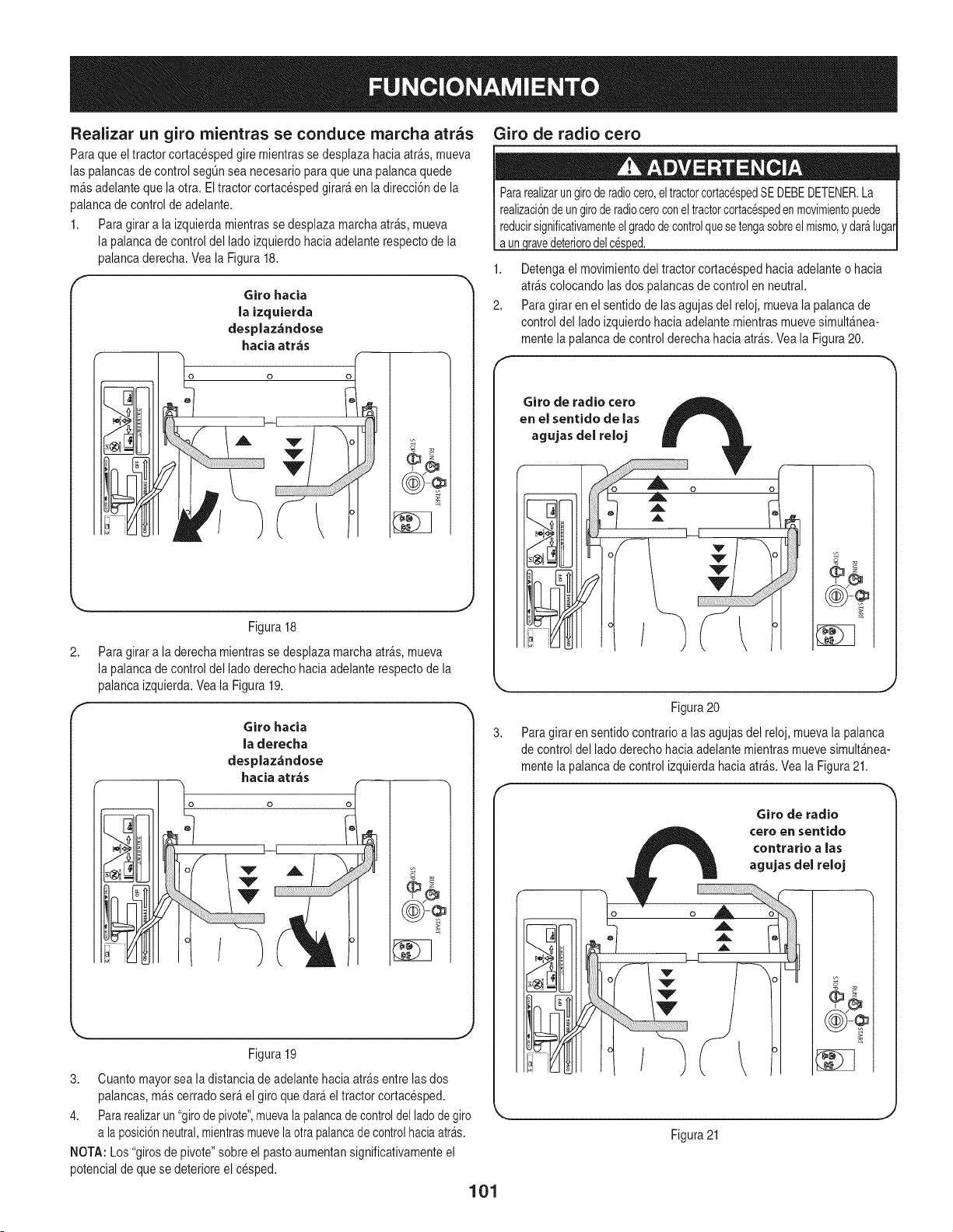
Realizar un giro rnientras se conduce marcha arras
Paraque eltractor cortacespedgire mientrasse desplazahacia atr_s, mueva
las palancasdecontrol segQnsea necesariopara que unapalancaquede
m_sadelantequela otra. Eltractor cortacespedgirar_ en la direcci6nde la
palancade controlde adelante.
1. Paragirara la izquierdamientrasse desplazamarchaatr&s,mueva
la palancadecontrol del lado izquierdohacia adelanterespectode la
palancaderecha.Veala Figura18.
r
Giro hacia
la izquierda
desplaz,-_ndose
hacia atr,_s
2,
f
Figura 18
Paragirar a la derechamientrassedesplazamarchaatr&s,mueva
la palancadecontrol del ladoderecho hacia adelanterespectode la
palancaizquierda.Veala Figura19.
o
o o
Giro hacia
la derecha
desplaz_ndose
hacia arras
Figura 19
J
3. Cuantomayorsea ladistanciade adelantehaciaatr&sentrelas dos
palancas,m&scerradoser_el giro quedar&el tractorcortacesped.
4. Pararealizarun"girode pivote",muevalapalancade controldel ladodegiro
a laposici6nneutral,mientrasmuevelaotra palancade controlhaciaatrAs.
NOTA: Los"giros de pivote"sobre el pastoaumentansignificativamenteel
potencialde que se deterioreel cesped.
101
Giro de radio cero
Pararealizarungiroderadiocero,eltractorcortac_spedSEDEBEDETENER.La j
realizaci6ndeungiroderadioceroconeltractorcortac_speden movimientopuede
reducirsignificativamenteelgradodecontrolquesetengasobreel mismo,y daralugar/
aun,qravedeteriorodelc@ped. |
1. Detengael movimientodel tractorcortacespedhaciaadelanteo hacia
arrascolocandolasdos palancasde controlen neutral.
2. Paragirar en el sentido delasagujas del reloj,mueva lapalanca de
control del ladoizquierdohaciaadelantemientrasmuevesimult_nea-
mentela palancade controlderecha haciaarras.Veala Figura20.
Giro de radio cero
en el sentido de las
agujas del reloj
((¢))-@
J
Figura20
Paragirar en sentido contrarioalas agujasdel reloj, muevala palanca
de controldel ladoderechohacia adelantemientrasmuevesimult_nea-
mentela palancade controlizquierdahacia arras.Vea la Figura21.
Giro de radio
¢ero en sentido
contrario a las
agujas del reloj
/
((®))-@
Figura21
Realizaci6n de una maniobra en '°Y"
Cuandoexistencondicionesde bajatracci6n,realiceestos procedimientos
para realizargiros de radio cero (la "maniobraen Y"):
Para girar en el sentidode lasagujasdel reloj (elfrentede la mAquinase
muevehaciael ladoDERECHO)al desplazarseHACIAADELANTE
1. Detengael tractor
2. Luegomuevalentamentelas palancasde control haciaarras(sin
superarla velocidadmaximamarchaarras) parainiciarel desplazamien-
to MARCHAATRAS,
3. Luegomuevalentamentela palancade controlIZQUIERDAhacia
adelantemientrasmantiene lapalanca de control DERECHAen la
posici6nde desplazamientohaciaarras.
4. Para detenerel giroy reiniciarel desplazamientoHACIAADELANTE,
muevalentamentela palancade control DERECHAde la posici6nde
desplazamientoMARCHAATRASa unaposici6nde desplazamiento
HAClAADELANTEiguala la de la palancade controlIZQUIERDA.
5. Para girosen sentidocontrarioalas agujas del reloj,realiceel
procedimientoa la inversa.
DETENCION DEL TRACTOR CORTACi_SPED
1. Muevalas dospalancasde control a la posici6nneutralpara detenerel
movimientodel tractorcortacesped.
2. Presioneel interruptorde latoma defuerza (PTO)haciaabajo a la
posici6nDESENGANCHADA.
3. Useel pedalde elevaci6nde la plataformapara levantarla mismaa su
posici6nmAsalta.
4. Si desciendedel tractorcortacesped,muevalas palancasdecontrol
totalmentehacia afueraenla posici6nneutral,engancheel frenode
mano,muevala palancadecontrol del aceleradora la posici6nVELO-
ClDADR_,PIDA_[7, gireel interruptordeencendidoa la posici6n@
PARADAy retirela Ilavedel interruptor.
Noabandoneel asiento del tractorcortacespedsin desengancharla toma
de fuerza(PTO); coloque laspalancasde controlde transmisi6ntotalmente
haciaafueraen posici6nneutral,y engancheelfreno demano.Si deja
el tractor cortacespedsinvigilancia,apagueel motorgirandola Ilavede
OPERACION EN PENDIENTES
Consulteindicadorde pendienteen la Secci6nFuncionamientoSeguropara
determinarenque pendientesno puedeoperarel tractorde manerasegura.
Nouse el tractor cortacespeden pendientescon una inclinaci6nde mAsde
15grados (elevaci6naproximadade 2Y2pies porcada 10 pies). El tractor
cortacespedpodriavoltearsey causar lesionesgraves.
1. Siempreconduzcael tractordeformatransversala la pendiente,nunca
haciaarribay haciaabajo.Controlelavelocidady la direcci6ndel tractor
cortacespedusandoprincipalmentela palancadecontrol del ladodel
tractorque queda'cuestaabajo',mientrasquela palancade controldel
lado'cuesta arriba' permaneceesencialmentefija.
2. En Io posibleevitegirar cuesta abajo.Comienceen la basede la
pendientey operecuestaarriba.Siemprereduzcalavelocidad antes
de dar la vuelta.
FUNCI0NAlVllENT0 DE LA T01VlADE FUERZA (PT0)
1. Opereel embraguedela toma de fuerza(PTO) dela siguienteforma:
2. Mueva la palancade controldel aceleradoraproximadamentea la
posici6nde aceleraci6nintermedia.
3. Tire del interruptorde latoma defuerza (PTO)hacia arribaa la
posici6nENGANCHADA.
4. Mueva la palancadel aceleradora la posici6nFAST_ (VELOCIDAD
R_,PIDA).
NOTA: Eloperadordebe permanecersentadoen el tractorcortacespeden
todo momento.Si el operadorabandonael asientosin apagarel interruptorde
la toma de fuerza,el motordel tractorcortacespedse detiene.
NOTA: Elembraguede latoma defuerza (PTO)no funcionacuandoel
tractorcortacespedse desplazaen marchaarras.La toma de fuerza (PTO)
se desenganchacuandolas dos palancasde control se colocanen posici6n
marchaarras,y se vuelvea engancharcuandouna (olas dos) palanca(s)de
control se mueve(n)a la posici6nneutralo de marchadirecta.
USO DE LA PLATAFORiVlA DE CORTE
Aseg@esequeel Areadondese va a cortar estelibrede desechos,ramitas,
piedras,cablesu otrosobjetosque puedanset arrojadospor las cuchillas
rotativas.
NOTA: Noenganchela plataformade la cortadoracuandoeste bajasobre
el pasto.Se produceel desgasteprematuroy la posiblefalla de la correa
en "V"y del embraguede la tomade fuerza(PTO). Antesdeengancharla
plataformade corte,levantetotalmentela plataformao Ilevela mAquinaa un
Areadonde nohayacesped.
1. Corte de formatransversala la pendiente,no haciaarriba ni haciaabajo.
Si corta el cespeden pendiente,comiencepor la basey desplAcese
haciaarriba para asegurarque siemprese gire cuestaarriba.
2. AI realizarlaprimerapasadaelijaun puntodel ladoopuestodelAreaa cortar.
3. Enganchela toma de fuerza (PTO) y muevaelcontrol del aceleradora
la posici6nFAST_ (velocidadr@ida).
4. Baje la plataformade corte al ajustede altura deseadousandola manija
de elevaci6nde plataforma.
5. Empujelas palancasde controldel ladoderechoy del ladoizquierdo
lentamentehaciaadelantey de forma parejaparaque eltractor
cortacespedavance,ymantengalaorientaci6n deltractor cortacesped
en linearecta haciael puntode alineaci6n.
NOTA: La velocidaddel tractorcortacespedafecta la calidaddel corte. Si
realizael corte a maximavelocidad lacalidadse ve afectadanegativamente.
Controlelavelocidadabsolutacon las palancasde control.
6. Cuando seacerque alotro extremode lafranja, reduzcalavelocidado
detengaseantes de girar.Se recomiendarealizar un giro en U a menos
que sea necesariorealizarun girode radio cero.
7. Alineela cortadorade cespedcon un horde dela franjacortaday
superpongala pasadaaproximadamente3 pulgadas.
8. Orienteel tractorcortacespeden cadafranja subsiguientede modoque
se alineecon lafranja ya cortada.
3. Pongaespecialcuidado y conduzcalentamenteal girar cuesta abajo.
102
9. Paraevitar laformaci6nde surcoso ranurasen el cesped,en Io posible
var[ela direcci6nde lasfranjas de corte aproximadamente450en cada
corte subsiguiente.
Tengasumo cuidadoal atravesarsenderosde grava o caminosde acceso.
Desenganchela toma de fuerza(PTO) y levantela plataformahastala
posici6nm_s alta antesde cruzar.
NOTA:Siempreque detengaeltractor cortacespedpotcualquierraz6n en un
_rea de cesped, hagaIo siguiente:
• Coloquela palancadecambios en neutral,
• Coloqueel frenode mano,O,
• Apagueel motory retirela Ilave.
, Eso permitir#,reduciral m[nimola posibilidadde quesu cespedre-
suitequemadopot elescapecalientedel motoren funcionamiento.
CONTROL DE LOS ClRCUITOS DE BLOQUEO
DE SEGURIDAD
Controleperi6dicamenteloscircuitosde bloqueode seguridadparaestar
segurode quefuncionanadecuadamente.Si algunode loscircuitosde
seguridadnofunciona conformeal dise_o,Ilameal 1-800-659-5917para
programarel serviciode inspecci6ndel tractor de Piezasy Reparaci6nde
Sears,a losefectosde quese inspeccionesu tractorcortacesped.NOuse
eltractor cortacespedsi algQncircuitode seguridadno est_funcionando
adecuadamente.Paracontrolarloscircuitosde seguridadprocedade la
siguientemanera:
1. Sentadoen el asientodel tractor cortacespedcon ambas palancasde
controltotalmenteabiertas hacia afuera,DESENGANCHEel frenode
mano O y moment_neamentegire el interruptorde encendidoa la
posici6nde ARRANQUE(_. El motor no debe intentararrancar.
2. ENGANCHEel frenode manoO ytire del interruptorde latoma de
fuerza(PTO) haciaarriba a la posici6nENGANCHADA.(_ Gireel
interruptorde encendidoa laposici6nde ARRANQUEmoment_nea-
mente;el motorno deber[aintentararrancar.
3. Empujeel interruptorde latoma defuerza(PTO) haciaabajo,a la posi-
ci6n DESENGANCHADA,O. y COLOQUEel frenode mano.Arranque
el motory muevaunade laspalancasde controldesde la posici6n
neutraltotalmentehacia afuera. El motordebedejar de funcionar. Repita
el procedimientocon la otra palancade control.
4. Muevalasdos palancasde controltotalmentehaciaafueraen laposici6n
neutraly DESENGANCHEel frenode mano_; luego levantehacia
arribadesdeel asientodel operador.Elmotordebedejar de funcionar.
5. Con lasdos palancasde controltotalmentehaciaafuera en la posici6n
neutraly elfrenode manoCOLOCADO,ENGANCHEla PTO.Levante
haciaarribadesdeel asiento del operador;el motorse debedetener.
6. Arranqueeltractor cortacesped,DESENGANCHEelfreno de manoO
y muevalas palancasde control hacia adentroa la posici6noperativa
neutral.Enganchelatoma defuerza (PTO)y muevalas dos palancas
de control lentamentea la posici6nmarchaatr_s;latoma de fuerza
(PTO)se debe desenganchary la plataformade corte se debe detener
hastaque unao lasdos palancasde controlse coloca(n) en posici6n
neutralo de marchadirecta.
103
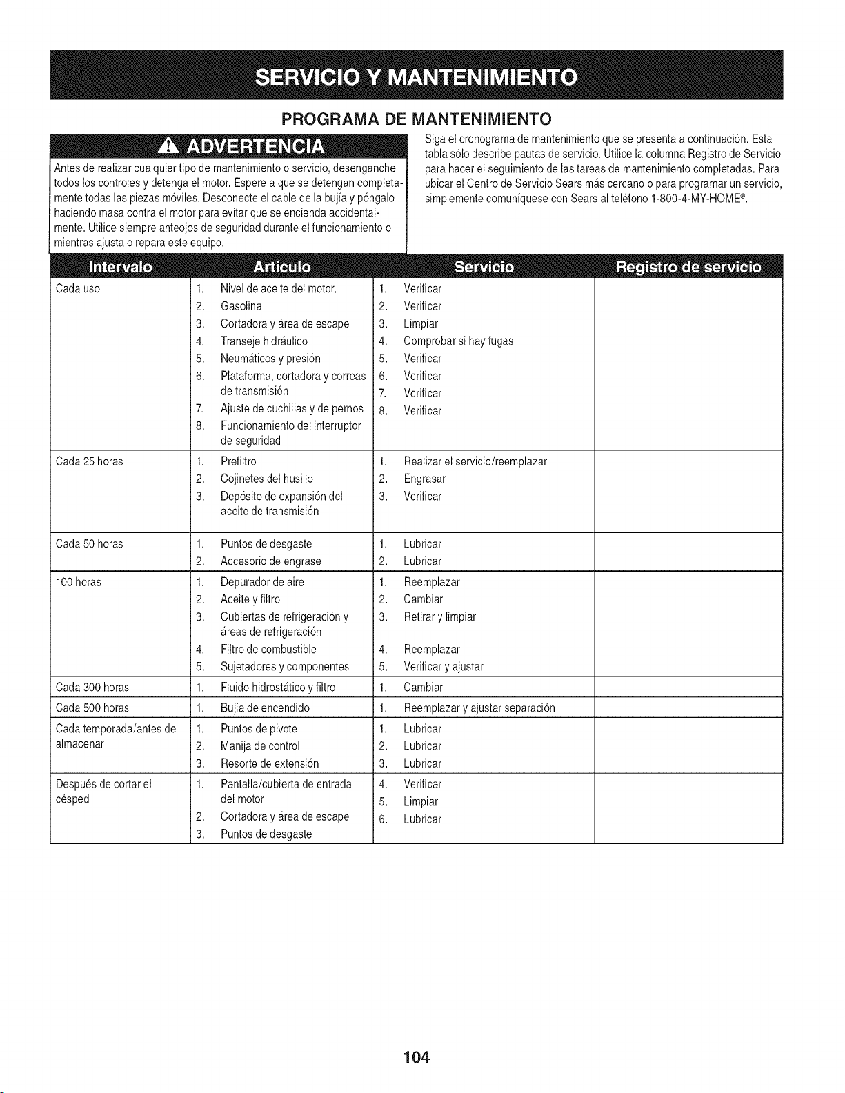
PROGRAIVlADE iVlANTENIMIENTO
Antesde realizarcualquiertipo demantenimientoo servicio,desenganche
todos loscontrolesy detengael motor.Esperea quese detengancompleta-
mentetodas las piezasm6viles.Desconecteelcable de la bujia y p6ngalo
haciendomasacontrael motorparaevitarquese enciendaaccidental-
mente.Utilicesiempreanteojosde seguridadduranteel funcionamientoo
mientrasajustao reparaeste equipo.
Cadauso
Cada25 horas
Cada50 horas
100horas
Cada300 horas
Cada500 horas
Cadatemporada/antesde
almacenar
Despuesde cortarel
cesped
1. Nivelde aceitedel motor.
2. Gasolina
3. CortadorayArea de escape
4. TransejehidrAulico
5. NeumAticosypresi6n
6. Plataforma,cortadoray correas
de transmisi6n
7. Ajustede cuchillasy de pernos
8. Funcionamientodelinterruptor
de seguridad
1. Prefiltro
2. Cojinetesdelhusillo
3. Dep6sitodeexpansi6ndel
aceitede transmisi6n
1. Puntosdedesgaste
2. Accesoriodeengrase
1. Depuradordeaire
2. Aceitey filtro
3. Cubiertasderefrigeraci6ny
Areasde refrigeraci6n
4. Filtrode combustible
5. Sujetadoresycomponentes
1. FluidohidrostAticoy filtro
1. Bujia de encendido
1. Puntosdepivote
2. Manijade control
3. Resortede extensi6n
1. Pantalla/cubiertade entrada
del motor
2. CortadorayArea de escape
3. Puntosdedesgaste
Siga el cronogramade mantenimientoquese presentaa continuaci6n.Esta
tabla s61odescribepautas de servicio.Utilice la columnaRegistrode Servicio
para hacerel seguimientode lastareasde mantenimientocompletadas.Para
ubicarel Centrode ServicioSears mAscercanoo para programarun servicio
simplementecomuniquesecon Sears altelefono 1-800-4-MY-HOME®.
1. Verificar
2. Verificar
3. Limpiar
4. Comprobarsi hayfugas
5. Verificar
6. Verificar
7. Verificar
8. Verificar
1. Realizarel servicio/reemplazar
2. Engrasar
3. Verificar
1,
2.
1.
2.
3.
Lubricar
Lubricar
Reemplazar
Cambiar
Retirary limpiar
4. Reemplazar
5. Verificary ajustar
1. Cambiar
1. Reemplazary ajustarseparaci6n
1. Lubricar
2. Lubricar
3. Lubricar
4. Verificar
5. Limpiar
6. Lubricar
104
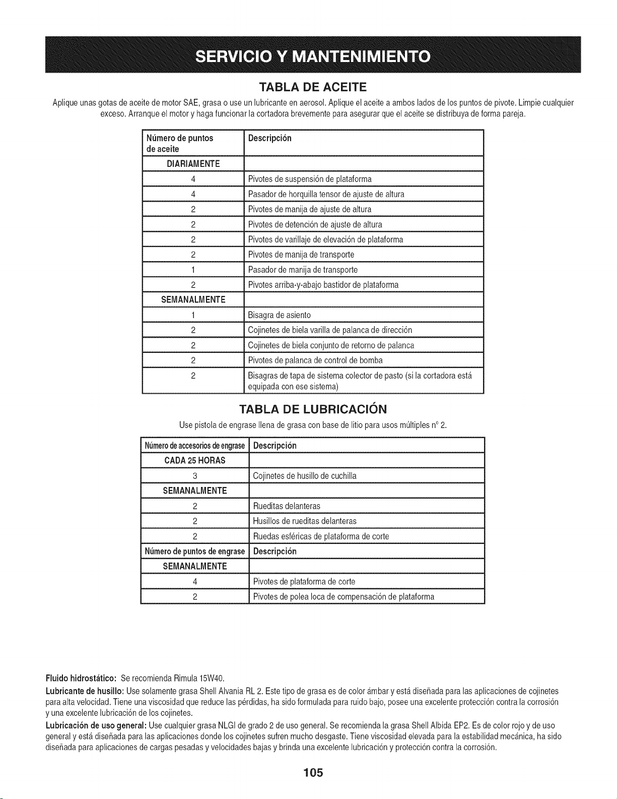
TABLA DE ACEITE
Apliqueunasgotas de aceitede motorSAE,grasa o use unlubricanteen aerosol.Aplique elaceite a ambosladosde los puntosde pivote.Limpiecualquier
exceso.Arranqueel motory hagafuncionarla cortadorabrevementepara asegurarque el aceitesedistribuyade formapareja.
N_mero de puntos DescripciSn
de aceite
DIARIAMENTE
4 Pivotesde suspensi6nde plataforma
4 Pasadorde horquillatensorde ajustede altura
2 Pivotesde manijade ajustede altura
2 Pivotesde detenci6nde ajustede altura
2 Pivotesde varillaje de elevaci6nde plataforma
2 Pivotesde manijade transporte
1 Pasadordemanijade transporte
2 Pivotesarriba-y-abajobastidorde plataforma
SEMANAWENTE
1 Bisagrade asiento
2 Cojinetesde bielavarilla de palancade direcci6n
2 Cojinetesde bielaconjuntode retornode palanca
2 Pivotesde palancade control de bomba
2 Bisagrasde tapa de sistemacolectorde pasto (si la cortadoraest_
equipadacon ese sistema)
TABLA DE LUBRICACION
Usepistolade engraseIlenade grasa con basede litio parausosm_ltiplesno2.
N_merodeaccesoriosdeengrase DescripciSn
CADA25 HORAS
3 Cojinetesde husillodecuchilla
SEMANAWENTE
2 Rueditasdelanteras
2 Husillosde rueditasdelanteras
2 Ruedasesfericasde plataformadecorte
Numerede puntosde engrase DescripciSn
SEMANAWENTE
4 Pivotesde plataformade corte
2 Pivotesde poleaIocade compensaci6nde plataforma
Fluido hidrost_tico: Se recomiendaRimula15W40.
Lubricante de husillo: Use solamentegrasa ShellAlvania RL2. Estetipo degrasa es decolor _mbary est_diseSadapara las aplicacionesde cojinetes
para alta velocidad.Tiene unaviscosidadque reducelas perdidas,hasido formuladapara ruidobajo,posee unaexcelenteprotecci6ncontrala corrosi6n
y unaexcelentelubricaci6nde loscojinetes.
Lubricaci6n de uso general: Usecualquiergrasa NLGIde grado2 de usogeneral.Se recomiendala grasaShell AlbidaEP2.Es de color rojoy de uso
generaly est&diseSadaparalas aplicacionesdonde loscojinetessufrenmuchodesgaste.Tieneviscosidadelevadapara la estabilidadmec_nica,ha sido
diseSadaparaaplicacionesde cargas pesadasy velocidadesbajasy brindaunaexcelentelubricaci6ny protecci6ncontrala corrosi6n.
105
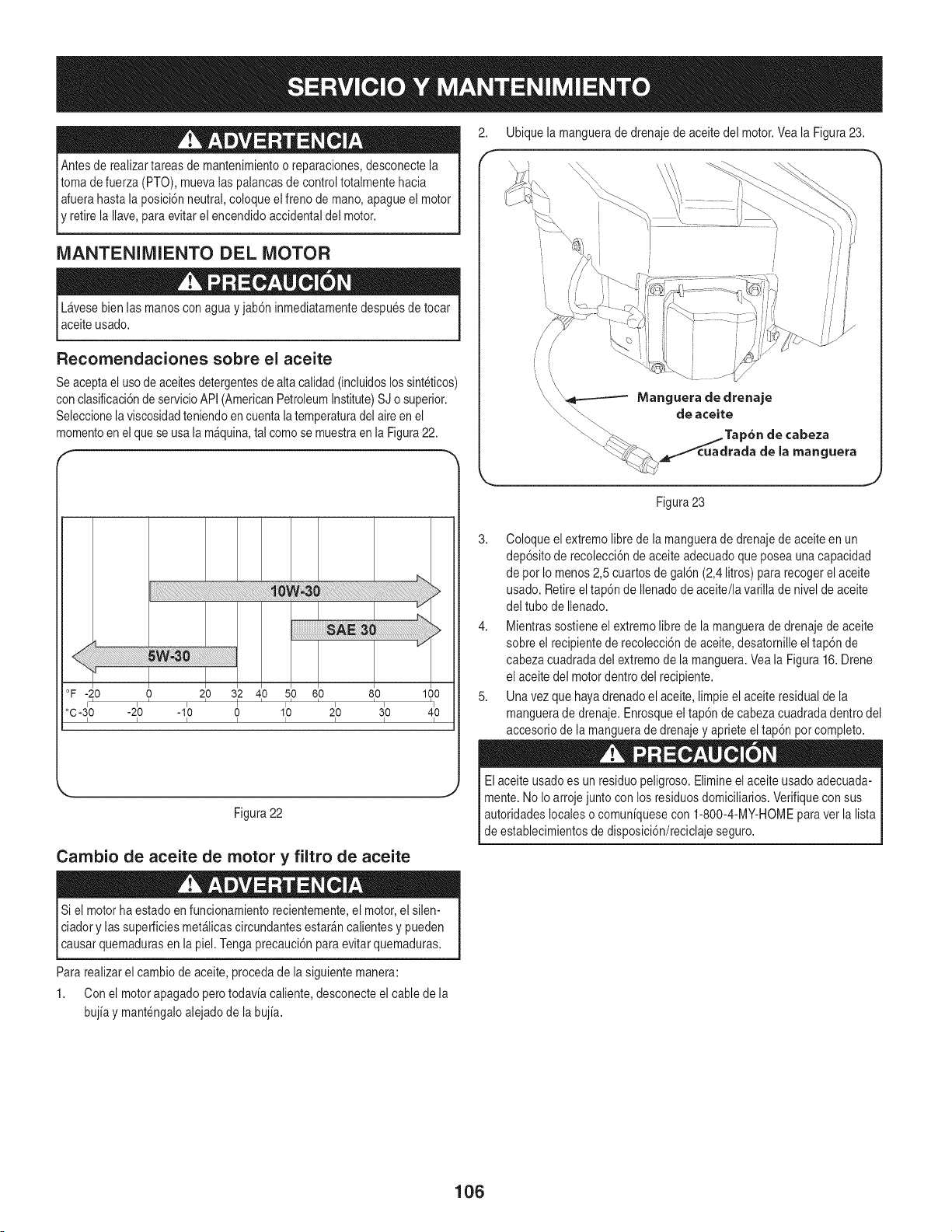
Antesde realizartareas demantenimientoo reparaciones,desconectela
tomade fuerza (PTO), muevalas palancasdecontroltotalmentehacia
Iafuerahasta laposici6nneutral,coloqueel freno de mano,apagueel motor
E retirela Ilave,paraevitarel encendidoaccidentaldel motor.
MANTENIMIENTO DEL MOTOR
Lavesebien las manosconagua y jab6ninmediatamentedespuesdetocar
aceiteusado.
Recomendaciones sobre el aceite
Se aceptaeluso deaceitesdetergentesde altacalidad(incluidoslossinteticos)
con clasificaci6nde servicioAPI (AmericanPetroleumInstitute)SJ o superior.
Seleccionelaviscosidadteniendoen cuentalatemperaturadelaireen el
momentoen el quese usa lam_quina,tal comose muestraen la Figura22.
°F-20 0 210 312 410 510 610 810 1(30
o0-3:o-2:o -1:o o 1:o 2:o 3:o 4:o
J
Figura22
Cambio de aceite de motor y filtro de aceite
Si el motorha estadoenfuncionamientorecientemente,el motor,el silen-
ciadory las superficiesmet_licascircundantesestar_ncalientesy pueden
_causarquemadurasen a p e. Tengaprecauc6n paraevtar quemaduras.
Para realizarel cambiode aceite,procedadela siguientemanera:
1. Con el motorapagado perotodavia caliente,desconecteel cablede la
bujia y mantengaloalejadode labujia.
2. Ubiquela manguerade drenajede aceitedel motor.Vea la Figura23.
3. Coloqueel extremo librede la manguerade drenajede aceiteen un
dep6sitode recolecci6nde aceiteadecuadoque poseaunacapacidad
de pot Io menos2,5cuartos de gal6n(2,4 litros) para recogerel aceite
usado.Retireeltap6n de Ilenadodeaceite/la varilla de nivel de aceite
del tubo de Ilenado.
4. Mientrassostieneel extremolibre de la manguerade drenajede aceite
sobre el recipientede recolecci6nde aceite,desatornilleel tap6nde
cabezacuadradadel extremode lamanguera.Veala Figura 16.Drene
el aceitedel motordentro del recipiente.
5. Una vezque hayadrenadoel aceite, limpieel aceiteresidualde la
manguerade drenaje.Enrosqueel tap6n de cabezacuadradadentrodel
accesoriode la manguerade drenajey aprieteeltap6n potcompleto.
Elaceiteusadoes un residuopeligroso.Elimineel aceiteusado adecuada-
mente.No Ioarrojejunto con los residuosdomiciliarios.Verifiquecon sus
autoridadeslocaleso comuniquesecon 1-800-4-MY-HOMEpara vet la lista
de establecimientosde disposici6n/reciclajeseguro.
106
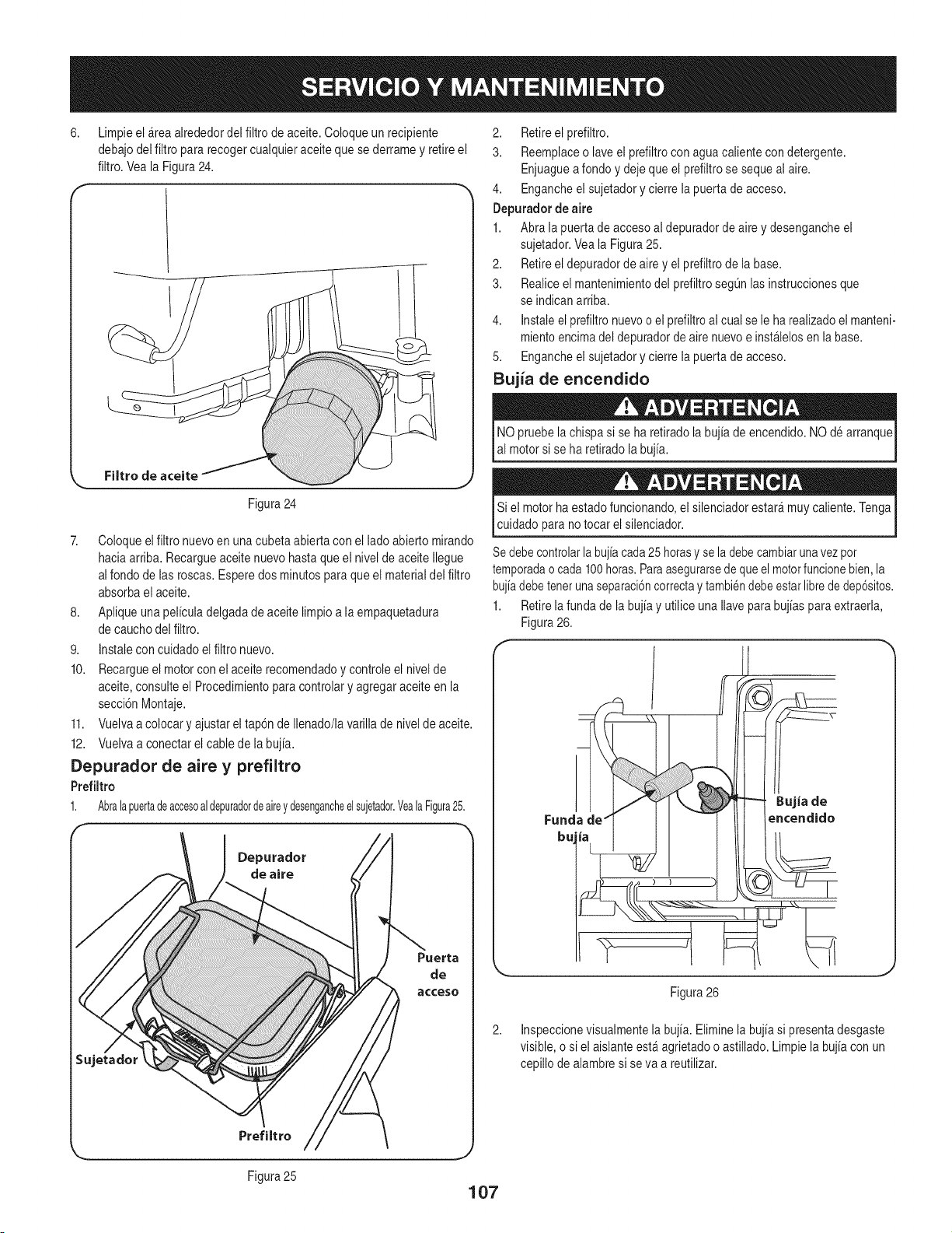
6,
Limpieel _rea alrededordel filtro de aceite.Coloque unrecipiente
debajodel filtro para recogercualquieraceitequese derramey retireel
filtro.Veala Figura24.
Filtro de aceite
Figura24
7. Coloqueelfiltro nuevoen unacubetaabierta con el ladoabiertomirando
haciaarriba. Recargueaceitenuevohastaque el nivelde aceiteIlegue
alfondo de las roscas.Esperedos minutospara queel materialdel filtro
absorbael aceite.
8. Apliqueuna peliculadelgadade aceite limpioa laempaquetadura
de cauchodel filtro.
9. Instalecon cuidadoelfiltro nuevo.
10. Recargueel motorconel aceite recomendadoy controleel nivelde
aceite,consulteel Procedimientoparacontrolary agregaraceiteen la
secci6nMontaje.
11. Vuelvaa colocary ajustarel tap6n de Ilenado/lavarillade nivelde aceite.
12. Vuelvaa conectarelcable de la bujia.
Depurador de aire y prefiltro
Prefiltro
1. Abralapuertadeaccesoaldepuradordeaireydesengancheel sujetador.YealaFigura25.
Depurador
de aire
2. Retireel prefiltro.
3. Reemplaceo laveel prefiltrocon agua calientecon detergente.
Enjuaguea fondoy dejequeel prefiltrose sequeal aire.
4. Engancheel sujetadory cierrelapuerta de acceso.
Depurador de aire
1. Abra la puerta de accesoal depuradorde aire y desengancheel
sujetador.Veala Figura25.
2. Retireel depuradorde airey el prefiltrode la base.
3. Realiceel mantenimientodel prefiltrosegOnlas instruccionesque
se indicanarriba.
4. Instaleel prefiltronuevoo el prefiltroal cual se le harealizadoel manteni-
mientoencimadel depuradorde airenuevoe instalelosen labase.
5. Engancheel sujetadory cierrelapuerta de acceso.
Bujia de encendido
NO pruebela chispa si se ha retiradola bujia de encendido.NO de arranque
al motorsi se ha retiradolabujia.
Si el motorha estadofuncionando,el silenciadorestar_muy caliente.Tenga
cuidadopara no tocar el silenciador.
Sedebecontrolarlabujiacada25 horasyse ladebecambiarunavezpot
temporadao cada100horas.Paraasegurarsede queel motorfuncionebien,la
bujiadebetenerunaseparaci6ncorrectay tambi6ndebeestarlibrede dep6sitos.
1. Retirela funda de labujia y utilice unaIlaveparabujias para extraerla,
Figura26.
Inspeccionevisualmentela bujia.Eliminelabujia si presentadesgaste
visible,o si el aislanteest_agrietadoo astillado.Limpie labujia con un
cepillo dealambresi seva a reutilizar.
Figura25
107
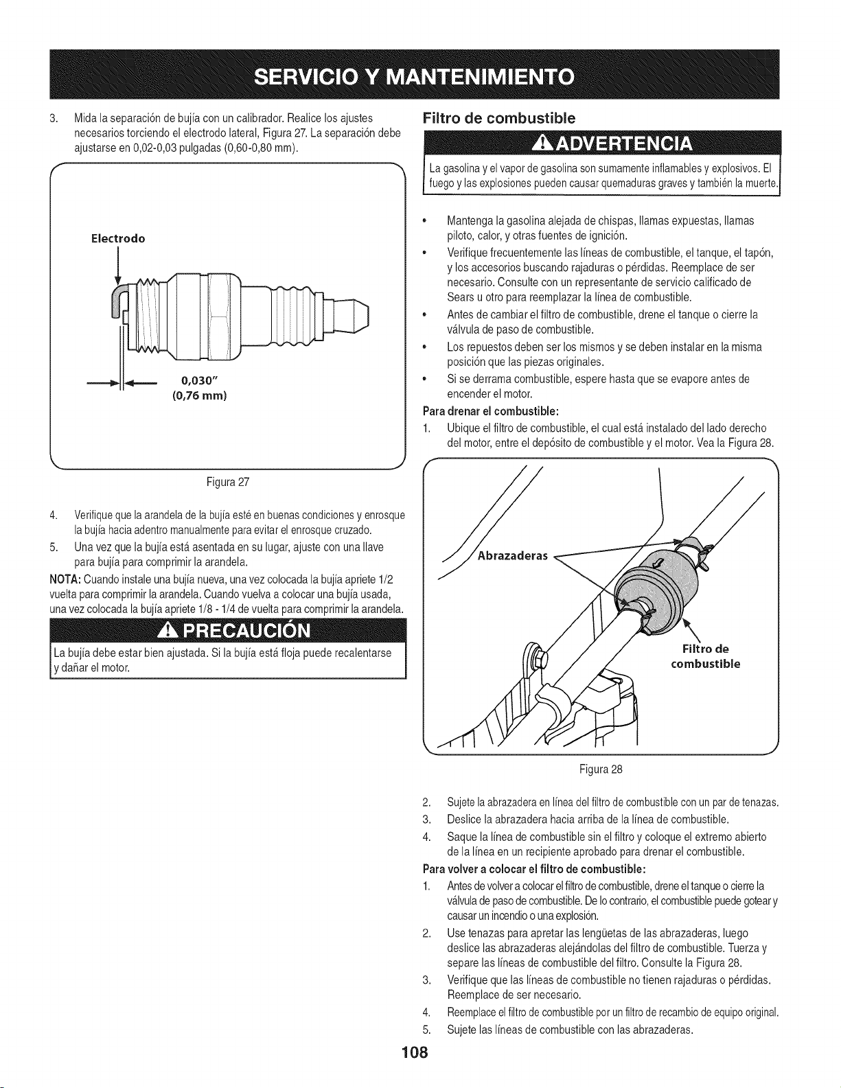
3. Midala separaci6ndebuj[acon un calibrador.Realicelosajustes
necesariostorciendoel electrodolateral,Figura27.La separaci6ndebe
ajustarseen 0,02-0,03pulgadas(0,60-0,80mm).
Electrodo
=======_
Figura27
4. Verifiquequelaarandelade labuj[aest6en buenascondicionesy enrosque
labuj[ahaciaadentromanualmenteparaevitarelenrosquecruzado.
5. Unavez que la buj[aesta asentadaen su lugar,ajustecon unaIlave
para buj[apara comprimirla arandela.
NOTA:Cuandoinstaleunabuj[anueva,unavezcolocadala buj[aapriete1/2
vueltaparacomprimirla arandela.Cuandovuelvaa colocarunabuj[ausada,
unavezcolocadala buj[aapriete1/8- 1/4 de vueltaparacomprimirla arandela.
'danar el motor.
Filtro de combustible
La gasolinay elvaporde gasolinasonsumamenteinflamablesy explosivos.El
fuegoy lasexplosionespuedencausarquemadurasgravesy tambi@lamuerte.
,, Mantengalagasolina alejadade chispas,llamasexpuestas,llamas
piloto,calor,y otrasfuentesde ignici6n.
,, Verifiquefrecuentementelas I[neasde combustible,el tanque, eltap6n,
y los accesoriosbuscandorajaduraso p@didas.Reemplacede set
necesario.Consultecon un representantede serviciocalificadode
Sears u otto parareemplazarla I[neade combustible.
,, Antesde cambiarel filtro decombustible,drene eltanqueo cierre la
v_lvula de pasode combustible.
,, Los repuestosdebenser losmismosy se debeninstalaren lamisma
posici6nque laspiezas originales.
,, Si se derramacombustible,esperehastaque se evaporeantesde
encenderel motor.
Paradrenar el combustible:
1. Ubiqueel filtrode combustible,el cual est_instaladodel ladoderecho
del motor,entre el dep6sitode combustibley el motor.Veala Figura28.
FiJtro de
combustible
Figura28
2. Sujetelaabrazaderaen I[neadelfiltrode combustiblecon unparde tenazas.
3. Deslicela abrazaderahacia arribade la I[neade combustible.
4. Saque la I[neade combustiblesin el filtroy coloque elextremoabierto
de la I[neaen un recipienteaprobadoparadrenarel combustible.
Paravolver a colocar el filtro de combustible:
1. Antesdevolvera colocarelfiltrodecombustible,dreneeltanqueocierrela
v_lvulade pasodecombustible.DeIocontrario,elcombustiblepuedegoteary
causarun incendioo unaexplosi6n.
2. Usetenazas para apretarlas lengOetasde las abrazaderas,luego
deslice lasabrazaderasalej_ndolasdel filtro de combustible.Tuerzay
separelas I[neasde combustibledel filtro. Consultela Figura28.
Verifiquequelas I[neasde combustibleno tienen rajaduraso p@didas.
Reemplacede sernecesario.
Reemplaceel filtrode combustiblepotun filtrode recambiodeequipooriginal.
Sujete lasI[neasdecombustiblecon lasabrazaderas.
3,
4.
5.
108
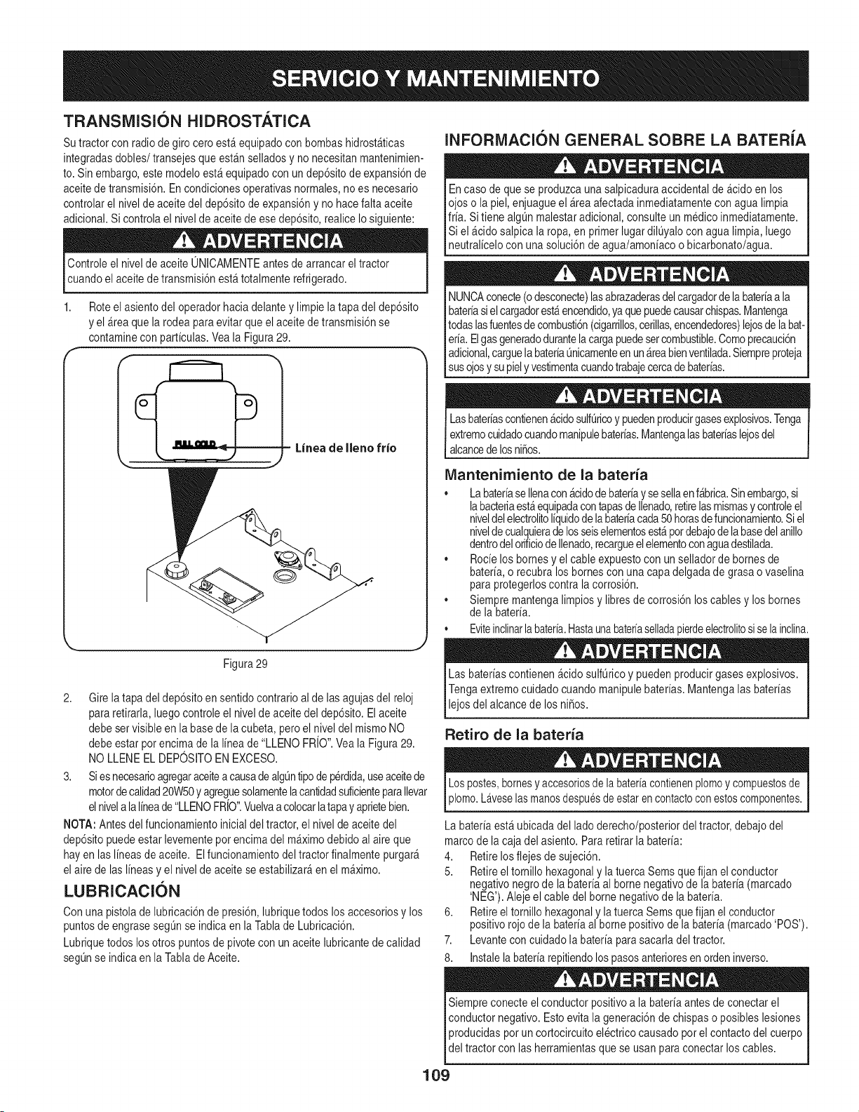
TRANSiVllSI6N HIDROSTATICA
Su tractorcon radiode giro cero est&equipadocon bombashidrost_ticas
integradasdobles/transejesque estanselladosy no necesitanmantenimien-
to. Sin embargo,estemodeloest_ equipadocon undep6sitode expansi6nde
aceitede transmisi6n.En condicionesoperativasnormales,no es necesario
controlarel nivelde aceitedel dep6sitode expansi6ny nohacefaltaaceite
adicional.Si controlael nivelde aceitede ese dep6sito,realiceIo siguiente:
Controleel nivelde aceiteONICAMENTEantesde arrancareltractor
cuandoel aceitede transmisi6nest_totalmenterefrigerado.
1,
Roteel asientodel operadorhacia delantey limpiela tapa del dep6sito
y el &teaque la rodeaparaevitarque el aceitede transmisi6nse
contaminecon parficulas.Vea la Figura29.
= Linea de Ileno frio
Figura29
2. Gire la tapadel dep6sitoen sentido contrarioal de lasagujasdel reloj
para retirarla,luegocontroleel nivelde aceitedel dep6sito.El aceite
debe set visibleen la basede la cubeta,peroel nivel del mismoNO
debe estar porencimade la I[neade "LLENO FRJO".Veala Figura29.
NO LLENEEL DEPOSlTOENEXCESO.
3. Si esnecesarioagregaraceiteacausadealgL_ntipode perdida,useaceitede
motorde calidad20W50y agreguesolamentelacantidadsuficienteparaIlevar
elnivelalaIfneade"LLENOFRiO".Vuelvaa colocarlatapay aprietebien.
NOTA:Antesdel funcionamientoinicial deltractor, el nivelde aceitedel
dep6sitopuedeestar levementepor encimadel m_ximodebidoalaire que
hay en las Ifneasde aceite. El funcionamientodeltractor finalmentepurgar_
el airede lasIfneasy el nivelde aceitese estabilizar_en el m_ximo.
LUBRICACI6N
Con unapistolade lubricaci6nde presi6n,lubriquetodos losaccesoriosy los
puntosde engrasesegQnse indica en laTablade Lubricaci6n.
Lubriquetodos losotros puntosde pivotecon un aceitelubricantedecalidad
segQnse indica en la Tablade Aceite.
INFORMACI6N GENERAL SOBRE LA BATERIA
Encaso de quese produzcaunasalpicaduraaccidentalde _cido enlos
ojos o lapiel, enjuagueel _reaafectadainmediatamentecon agua limpia
frfa. Si tiene algL_nmalestaradicional,consulte un medicoinmediatamente.
Si el _cido salpica la ropa,en primer lugardilQyalocon agua limpia,luego
neutral[celocon una soluci6nde agua/amon[acoo bicarbonato/agua.
NUNCAconecte(odesconecte)lasabrazaderasdelcargadorde labater[aa la I
bater[asi elcargadorest_encendido,yaquepuedecausarchispas.Mantenga I
todaslasfuentesdecombusti6n(cigarrillos,cerillas,encendedores)lejosdela bat-I
er[a.Elgasgeneradodurantelacargapuedesetcombustible.Comoprecauci6n I
adicional,carguela bater[aL_nicamenteen un&teabienventilada.SiempreprotejaI
lsus oosy supe y vestmentacuandotrabaecercade bateras. 1
Lasbaterfascontienen_cidosulfLiricoy puedenproducirgasesexplosivos.Tenga
extremocuidadocuandomanipulebaterfas.Mantengalasbaterfaslejosdel
alcancede losni_os.
IVlantenimiento de la baterfa
• Labaterfasellenacon&cidodebaterfay sesellaen f&brica.Sinembargo,si
labacteriaest_equipadacontapasde Ilenado,retirelasmismasy controleel
niveldelelectrolitoIfquidode la baterfacada50horasde funcionamiento.Si el
nivelde cualquierade losseiselementosest&pordebajode labasedelanillo
dentrodelorificiode Ilenado,recargueelelementoconaguadestilada.
• Rode los bornesy el cableexpuestocon un selladorde bornesde
baterfa,o recubra losbornescon una capadelgadade grasao vaselina
para protegerloscontrala corrosi6n.
• Siempre mantengalimpiosy libresde corrosi6nlos cablesy loshomes
de la baterfa.
, Eviteinclinarlabaterfa.Hastaunabaterfaselladapierdeelectrolitosiselainclina.
Las baterfascontienen_cidosulfL_ricoy puedenproducirgasesexplosivos.
Tengaextremocuidadocuandomanipulebaterfas.Mantengalas baterfas
I e os de a cancede os n 5os.
[
Retiro de la bateria
_lomo.L_veselasmanosdespu6sde estarencontactoconestoscomponentes.
La baterfaest&ubicadadel ladoderecho/posteriordel tractor,debajodel
marcode lacaja del asiento.Pararetirar la baterfa:
4. Retirelos flejesde sujeci6n.
5. Retireel tornillo hexagonaly latuercaSemsque fijan el conductor
negativonegrodela baterfaal bornenegativode la baterfa(marcado
'NEG').Alejeel cable del bornenegativode la baterfa.
6. Retireel tornillohexagonaly latuercaSemsquefijan el conductor
positivorojode la baterfaal bornepositivodela baterfa(marcado'POS').
7. Levantecon cuidadola baterfaparasacarladel tractor.
8. Instalela baterfarepitiendolospasosanterioresen ordeninverso.
Siempreconecte elconductor positivoa labater[aantes de conectarel
conductornegativo.Esto evita lageneraci6nde chispas o posibleslesiones
producidasporun cortocircuitoelectrico causadopor el contactodel cuerpo
de tractor con as herramentasque se usanpara conectar os cabes.
109
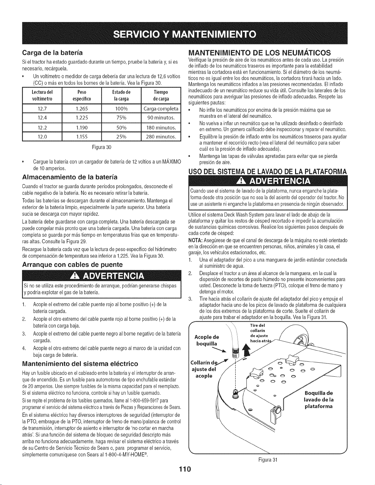
Cargade la bateria
Siel tractor haestado guardadodurante un tiempo,pruebela bateriay,si es
necesario,rec_rguela.
• Unvoltimetroo medidorde carga deberiadar una lecturade 12,6voltios
(CO)o m_s en todos los bornesde la bateria.Veala Figura30.
Lecturadel Peso Estadode Tiempo
voltimetro espedfico la carga
MANTENIMIENTO DE LOS NEUMATICOS
Verifiquela presi6nde airede losneum_ticosantesdecada uso.La presi6n
de infladodelos neum&ticostraseroses importantepara la estabilidad
mientrasla cortadoraest&enfuncionamiento.Si el all&metrode los neum_-
ticos no es igual entrelos dos neum_ticos,lacortadoratirar&haciaun lado.
Mantengalosneum_ticosinfladosa las presionesrecomendadas.El inflado
inadecuadode un neum_ticoreducesuvida 0til.Consultelos lateralesde los
decarga neum_ticospara averiguarlas presionesde infladoadecuadas.Respetelas
siguientespautas:
12.7 1.265 100% Carga corn pleta
12.4 1.225 75% 90 minutos.
12.2 1.190 50% 180 minutos.
12.0 1,155 25% 280 minutos.
Figura 30
• Carguelabateriacon un cargadorde bateriade 12voltiosa un M_,XIMO
de 10amperios.
Alrnacenamiento de la bateria
Cuandoel tractorse guarda duranteperiodosprolongados,desconecteel
cablenegativode la bateria.Noes necesarioretirar labateria.
Todaslas bateriassedescarganduranteel almacenamiento.Mantengael
exteriordela baterialimpio,especialmentelaparte superior.Unabateria
suciase descargacon mayorrapidez.
La bateriadebe guardarseconcarga completa.Una bateriadescargadase
puedecongelarm_sprontoque unabateriacargada. Unabateriacon carga
completase guarda por m&stiempo en temperaturasfriasqueen temperatu-
rasaltas. Consultela Figura29.
Recarguelabateriacadavezque la lecturade pesoespecificodel hidr6metro
de compensaci6nde temperaturasea inferiora 1,225.Veala Figura30.
Arranque con cables de puente
Si no se utilizaeste procedimientode arranque,podriangenerarsechispas
y podriaexplotarel gas de la bateria.
1. Acopleel extremodel cable puenterojoal bornepositivo(+) de la
bateriacargada.
2. Acopleel otto extremodel cablepuenterojoal borne positivo(+) de la
bateriacon carga baja.
3. Acopleel extremodel cable puentenegroal bornenegativode la bateria
cargada.
4. Acopleel otto extremodel cablepuentenegroal marcode la unidadcon
bajacarga de bateria.
IVlantenimiento del sistema el_ctrico
Hayunfusibleubicadoen el cableadoentrelabater[ay elinterruptorde arran-
quede encendido.Es unfusibleparaautomotoresdetipo enchufableest&ndar
de 20 amperios.Usesiemprefusiblesde la mismacapacidadparael reemplazo.
Siel sistemael6ctriconofunciona,controlesi hayun fusiblequemado.
Sise repiteelproblemadelosfusiblesquemados,Ilameal 1-800-659-5917para
programarelserviciodelsistemaelectricoa travesdePiezasy ReparacionesdeSears.
En el sistemaelectricohay diversosinterruptoresde seguridad(interruptorde
la PTO,embraguede la PTO,interruptorde frenode mano/palancade control
de transmisi6n,interruptorde asiento e interruptorde 'no cortar en marcha
arras'.Siunafunci6n del sistemade bloqueode seguridaddescriptom_s
arribano funcionaadecuadamente,haga revisarel sistemaelectrico a traves
de su Centrode ServicioTecnicode Sears o, para programarel servicio,
simplementecomun[quesecon Searsal 1-800-4-MY-HOME®.
• No infle los neum&ticospor encimade lapresi6nm_ximaque se
muestraen el lateraldel neum&tico.
, Novuelvaa inflarunneumaticoqueseha utilizadodesinfladoo desinflado
en extremo.Ungomerocalificadodebeinspeccionary repararelneumatico.
• Equilibrela presi6nde infladoentrelosneum_ticostraseros paraayudar
a mantenerel recorridorecto (veael lateraldel neum_ticopara saber
cu_l es la presi6nde infladoadecuada).
• Mantengalastapas de v_lvulasapretadaspara evitarquese pierda
presi6nde aire.
USO DEL SISTEIVlADE LAVADO DE LA PLATAFORIVlA
Cuandouseel sistemade lavadode laplataforma,nuncaenganchelaplata-
Iformadesdeotraposici6nqueno sea ladelasientodeloperadordeltractor.No
l useunasistenteni enganchelaplataformaenpresenciade ning0nobservador.
Utilice el sistemaDeck WashSystemparalavarel ladode abajode la
plataformay quitar losrestosde cespedrecortadoe impedirla acumulaci6n
de sustanciasquimicascorrosivas.Realicelossiguientespasosdespuesde
cada cortede cesped:
NOTA:Aseg0resedequeel canalde descargade la m_quinanoeste orientado
en ladirecci6nen que seencuentrenpersonas,niSos,animalesy lacasa,el
garaje,losvehiculosestacionados,etc.
1. Una el adaptadordel pico a una manguerade jardin est_ndarconectada
al suministrode agua.
2. Desplaceeltractora un _reaal alcancede la manguera,en lacual la
dispersi6nde recortesde pastohOmedono presenteinconvenientespara
usted.Desconectelatoma defuerza(PTO),coloqueelfrenode manoy
detengaelmotor.
3. Tire haciaatr&sel collarinde ajustedel adaptadordel pico y empujeel
adaptadorhaciauno delos picosde lavadodeplataformade cualquiera
de losdos extremosde la plataformade corte. Suelteel collarin de
ajuste paratrabar el adaptadoren la boquilla.Veala Figura31.
\\ Tire del
\ collarin
Acople de / deajuste
hacia atr6
boquilla
ajuste del
acopJe
Figura31
110
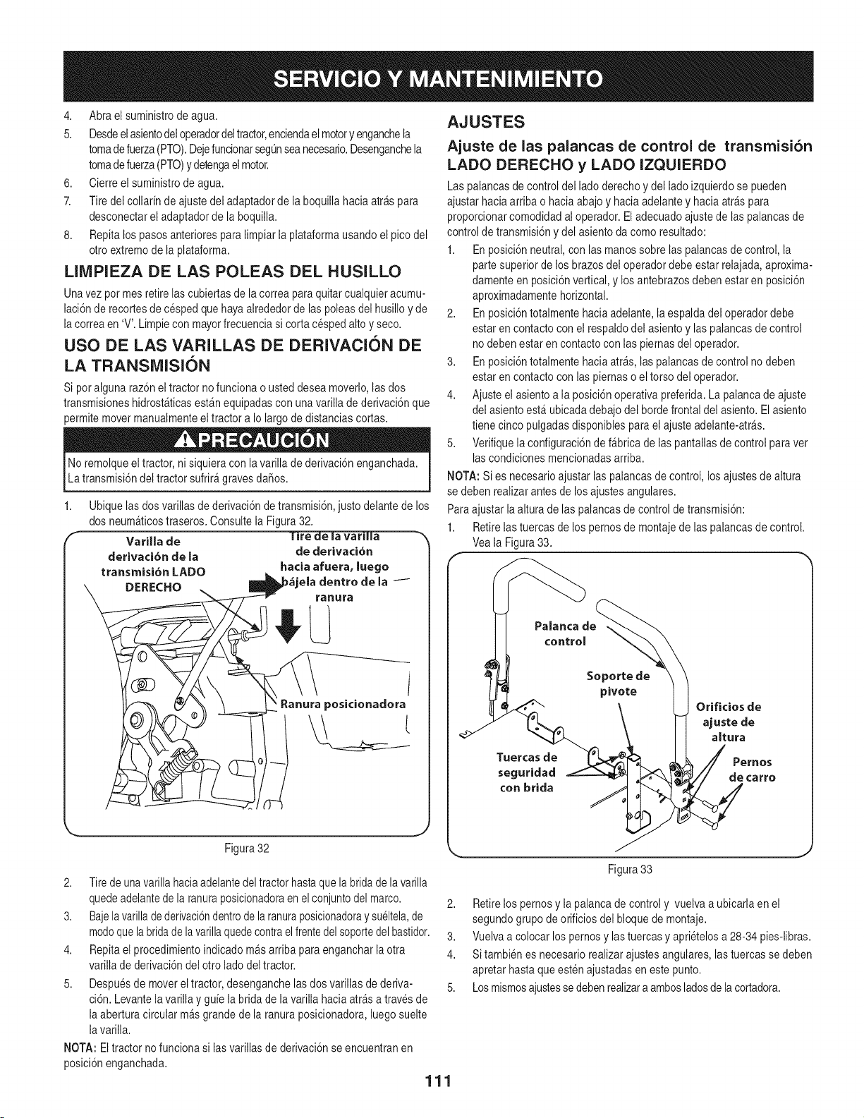
4. Abra el suministrode agua.
5. Desdeelasientodeloperadordeltractor,enciendael motoryenganchela
tomadefuerza(PTO).DejefuncionarsegQnseanecesario.Desenganchela
tomadefuerza(PTO)y detengaelmotor.
6. Cierreel suministrode agua.
7. Tire del collarinde ajustedel adaptadorde la boquillahacia arraspara
desconectarel adaptadorde la boquilla.
8. Repita lospasosanterioresparalimpiarla plataformausandoel pico del
otro extremodela plataforma.
LIIVlPIEZA DE LAS POLEAS DEL HUSILLO
Unavez pot mesretirelas cubiertasde lacorrea paraquitarcualquieracumu-
lacidnde recortesde cespedquehayaalrededorde las poleasdel husilloy de
la correaen 'V'. Limpiecon mayorfrecuenciasi corta cespedalto yseco.
USO DE LAS VARILLAS DE DERIVACION DE
LA TRANSiVlISION
Si poralgunaraz6n eltractor no funcionaousted desea moverlo,las dos
transmisioneshidrost_ticasest_nequipadasconunavarilla de derivaci6nque
permitemovermanualmenteeltractor a Io largo de distanciascortas.
No remolqueel tractor, nisiquiera con la varillade derivacidnenganchada.
La transmisidndel tractorsufrir_gravesda_os.
1,
Varilla de
derivaci6n de {a
transmisi6n LADO
DERECHO
Ubiquelasdos varillasde derivacidnde transmisidn,justo delantede los
dos neumaticostraseros.Consultela Figura32.
f_e i_-va_l]a -_
de derivaci6n
hacia afuera, luego
ela dentro de la /
ranura
i
Ranura poslcionadora
Figura32
2. Tirede unavarilla haciaadelantedeltractorhastaquela bridade la varilla
quedeadelantede la ranuraposicionadoraen el conjuntodel marco.
3. Bajelavarilladederivacidndentrode la ranuraposicionadoray su61tela,de
modoquelabridade lavarillaquedecontraelfrentedelsoportedelbastidor.
4. Repita el procedimientoindicadom_sarribapara engancharla otra
varillade derivacidndel otto ladodel tractor.
5. Despuesde moverel tractor,desenganchelasdos varillasde deriva-
cidn. Levantela varillay guie la bridade lavarilla haciaatr_s a travesde
la aberturacircularm_s grande de la ranura posicionadora,luegosuelte
lavarilla.
AJUSTES
Ajuste de las palancas de control de transmisi6n
LADO DERECHO y LADO IZQL!IERDO
Las palancasde control del ladoderechoy del lado izquierdose pueden
ajustar haciaarribao haciaabajo y haciaadelantey haciaarras para
proporcionarcomodidadal operador.Eladecuadoajustede las palancasde
control de transmisidny del asientodacomo resultado:
1. En posicidnneutral,con lasmanossobre laspalancasde control, la
partesuperiorde los brazosdel operadordebe estar relajada,aproxima-
damenteen posicidnvertical, y losantebrazosdebenestar enposicidn
aproximadamentehorizontal.
2. En posicidntotalmentehaciaadelante,la espaldadel operadordebe
estar en contactocon el respaldodel asientoy las palancasde control
no debenestar en contactocon las piernasdel operador.
3. En posici6ntotalmentehaciaatr_s, las palancasdecontrol no deben
estar en contactocon las piernaso el torso del operador.
4. Ajusteel asientoa la posici6noperativapreferida.Lapalancade ajuste
del asientoest_ ubicadadebajodel hordefrontaldel asiento.El asiento
tiene cincopulgadasdisponiblespara el ajusteadelante-atr_s.
5. Verifiquelaconfiguracidnde f_bricade las pantallasde control paravet
lascondicionesmencionadasarriba.
NOTA:Sies necesarioajustar las palancasde control,losajustesde altura
se debenrealizarantesde losajustesangulares.
Paraajustar laaltura de laspalancasde controlde transmisidn:
1. Retirelas tuercasde los pernosde montajede las palancasde control.
Veala Figura33.
Paianca de
control
| Soporte de
| pivote
/ _ \ Orificios de
I" 5. °"°'°
l seguridad _ ,,_,, // de carro
con brida _Oj '
Figura33
2. Retirelos pernosy la palancade control y vuelva a ubicarlaen el
segundogrupode orificiosdel bloquede montaje.
3. Vuelvaa colocarlos pernosy lastuercasy aprietelosa 28-34pies-libras.
4. Si tambienes necesariorealizarajustesangulares,lastuercasse deben
apretarhastaque estenajustadasen estepunto.
5. Losmismosajustesse debenrealizaraambosladosde lacortadora.
NOTA: Eltractorno funcionasi lasvarillasde derivacidnse encuentranen
posicidnenganchada.
111
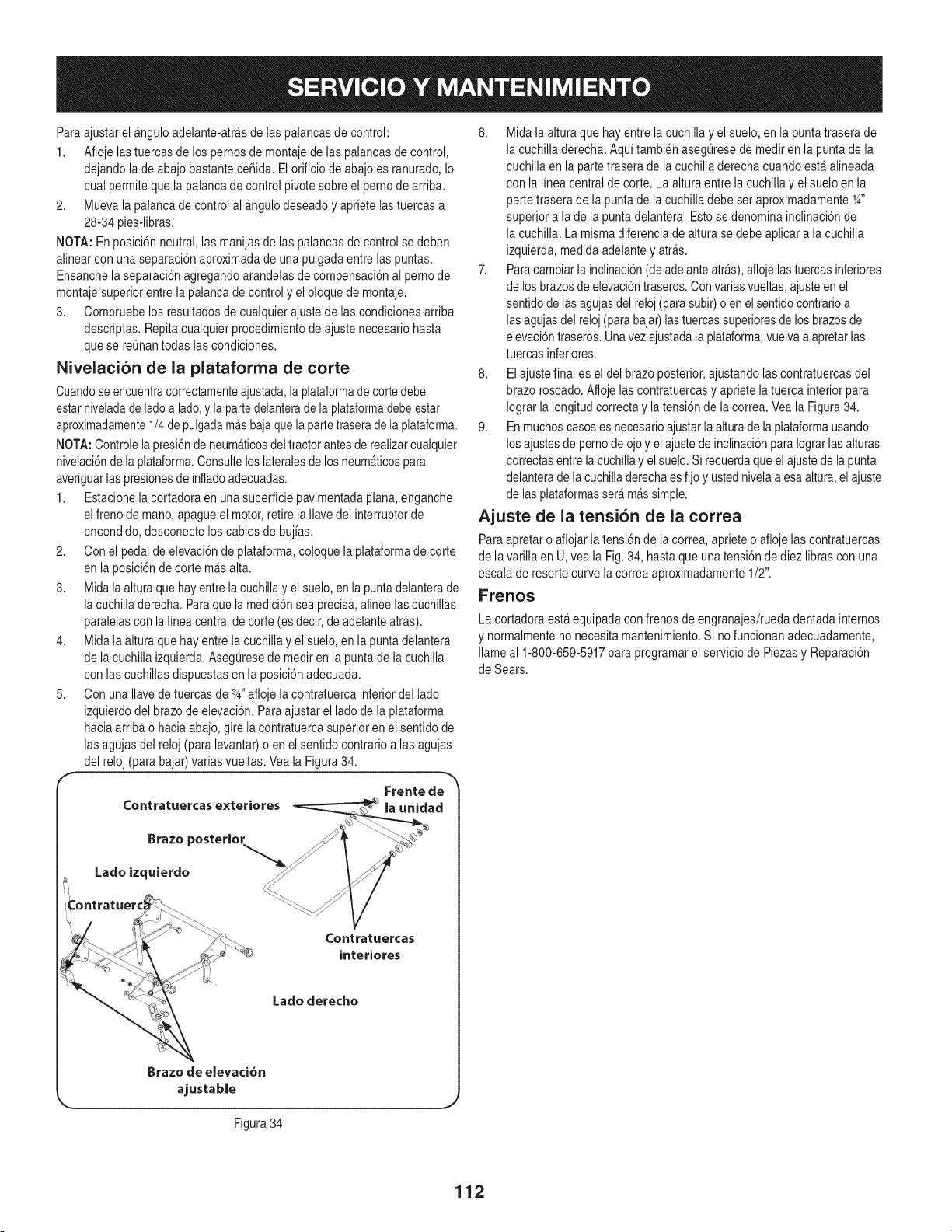
Para ajustarel &nguloadelante-atr&sde las palancasde control:
1. Afloje lastuercas de lospernosde montajede laspalancasde control,
dejandolade abajobastanteceSida.Elorificio de abajo es ranurado,Io
cual permitequela palancade controlpivotesobreel pernode arriba.
2. Muevala palancade controlal _ngulodeseadoyapriete lastuercasa
28-34pies-libras.
NOTA: Enposici6nneutral,las manijasde las palancasde control se deben
alinearcon unaseparaci6naproximadade unapulgadaentre laspuntas.
Ensanchela separaci6nagregandoarandelasdecompensaci6nal pernode
montajesuperiorentrela palancade control y el bloquede montaje.
3. Compruebelos resultadosdecualquierajustede lascondicionesarriba
descriptas.Repitacualquierprocedimientodeajustenecesariohasta
quese reQnantodas las condiciones.
Nivelaci6n de la plataforma de corte
Cuandoseencuentracorrectamenteajustada,la plataformade cortedebe
estarniveladade ladoa lado,y la partedelanterade la plataformadebeestar
aproximadamente1/4de pulgadamasbajaquela partetraserade la plataforma.
NOTA:Controlelapresi6nde neum_ticosdeltractorantesde realizarcualquier
nivelaci6nde laplataforma.Consultelos lateralesde los neum_ticospara
averiguarlaspresionesde infladoadecuadas.
1. Estacionela cortadoraen una superficiepavimentadaplana, enganche
elfreno demano,apagueel motor,retirelaIlave del interruptorde
encendido,desconectelos cablesde bujias.
2. Con el pedaldeelevaci6ndeplataforma,coloque laplataformade corte
en la posici6nde corte m&salta.
3. Midalaaltura quehay entrela cuchillayel suelo,en la puntadelanterade
lacuchilladerecha.Paraque lamedici6nsea precisa,alineelascuchillas
paralelascon la lineacentralde corte (esdecir,de adelanteatr#,s).
4. Midala alturaquehay entre lacuchillay el suelo,en la puntadelantera
de la cuchilla izquierda.AsegQresede medir en la punta de la cuchilla
con las cuchillasdispuestasen la posici6nadecuada.
5. Con unaIlavedetuercasde 3_,,afloje lacontratuercainferiordel lado
izquierdodel brazode elevaci6n. Paraajustarel lado de la plataforma
haciaarribao haciaabajo, girela contratuercasuperiorenel sentidode
lasagujas del reloj(para levantar)o en el sentidocontrario alas agujas
del reloj(para bajar)variasvueltas. Vea la Figura34.
Frente de
Contratuercas exteriores la unidad
6. Mida la alturaque hayentrela cuchillay elsuelo, enla puntatrasera de
la cuchilladerecha. Aqui tambienasegQresede mediren la puntade la
cuchilla enla partetraserade la cuchilladerechacuando est&alineada
con la linea centraldecorte. La alturaentre la cuchillayel sueloen la
partetrasera de la punta de lacuchilladebe ser aproximadamente1_,,
superiora lade la puntadelantera.Estose denominainclinaci6nde
la cuchilla.La mismadiferenciade altura se debe aplicara la cuchilla
izquierda,medidaadelantey atr_s.
7. Paracambiarlainclinaci6n(deadelanteart&s),aflojelastuercasinferiores
de losbrazosde elevaci6ntraseros.Convariasvueltas,ajusteen el
sentidode lasagujasdel reloj(parasubir)o en elsentidocontrarioa
lasagujasdel reloj(parabajar)lastuercassuperioresde losbrazosde
elevaci6ntraseros.Unavez ajustadalaplataforma,vuelvaa apretarlas
tuercasinferiores.
8. Elajustefinal es el del brazoposterior,ajustandolascontratuercasdel
brazo roscado.Aflojelascontratuercasy apriete la tuerca interiorpara
Iograr la Iongitudcorrectay la tensi6nde lacorrea. Veala Figura34.
9. Enmuchoscasoses necesarioajustarla alturade la plataformausando
losajustesde pernode ojo y elajustede inclinaci6nparaIograrlasalturas
correctasentrela cuchillay elsuelo.Si recuerdaqueel ajustede la punta
delanterade lacuchilladerechaes fijoy ustednivelaa esaaltura,el ajuste
de lasplataformasser_m&ssimple.
Ajuste de la tensi6n de la correa
Paraapretaro aflojarla tensi6nde la correa,aprieteo aflojelas contratuercas
de lavarilla en U,vea la Fig.34, hastaqueuna tensi6nde diez librascon una
escalade resortecurve lacorrea aproximadamente1/2".
Frenos
La cortadoraestaequipadaconfrenosde engranajes/ruedadentadainternos
y normalmenteno necesitamantenimiento.Si no funcionanadecuadamente,
Ilameal 1-800-659-5917paraprogramarel serviciode Piezasy Reparaci6n
de Sears.
Brazo posterior
Lado izquierdo
Contratuercas
interiores
Lado derecho
Brazo de elevaci6n
ajustable
Figura34
112
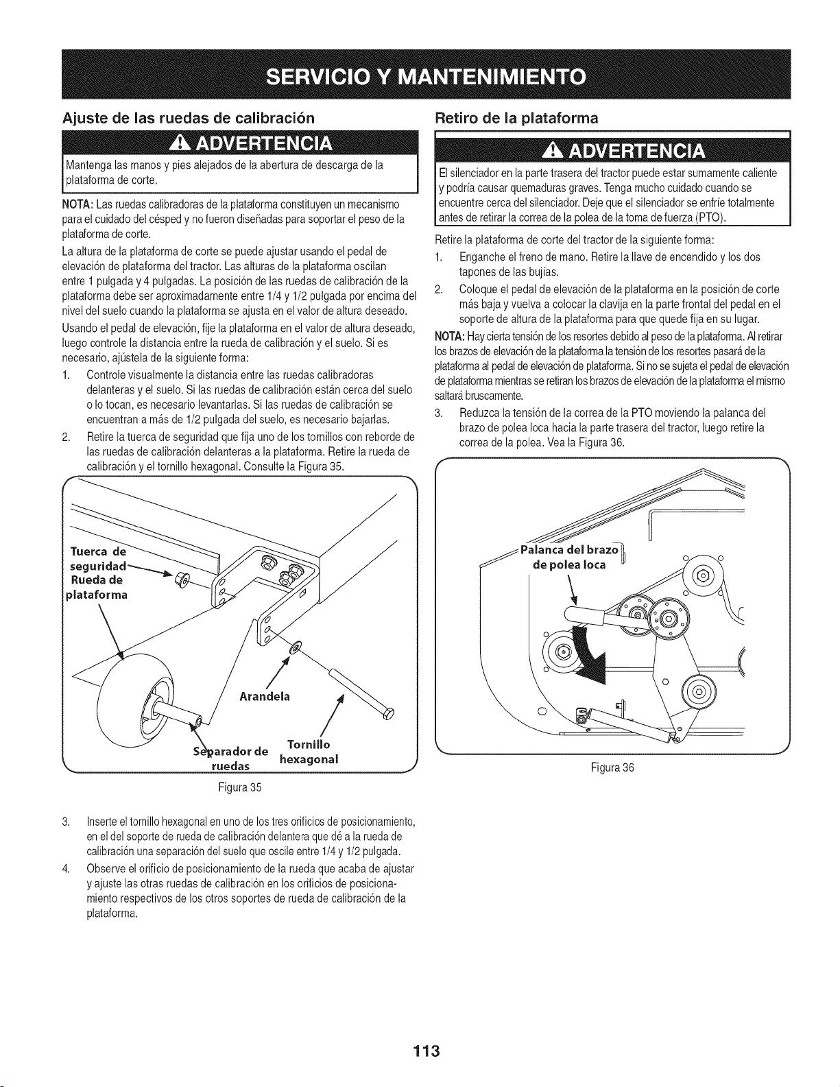
Ajuste de las ruedas de calibraci6n
Mantengalas manosy pies alejadosdela aberturade descargade la
plataformade corte.
NOTA:Las ruedascalibradorasde la plataformaconstituyenun mecanismo
parael cuidadodelcespedy nofuerondise6adasparasoportarel pesode la
plataformade corte.
La altura de la plataformade corte se puedeajustarusandoel pedalde
elevaci6nde plataformadel tractor.Las alturas de la plataformaoscilan
entre1 pulgaday 4 pulgadas.La posici6nde las ruedasde calibraci6nde la
plataformadebe ser aproximadamenteentre 1/4y 1/2 pulgadapor encimadel
niveldel suelocuandola plataformase ajustaen elvalorde altura deseado.
Usandoel pedalde elevaci6n,fije la plataformaen el valorde alturadeseado,
luegocontrolela distanciaentrela ruedadecalibraci6ny el suelo.Si es
necesario,ajQstelade lasiguienteforma:
1. Controlevisualmentela distanciaentrelas ruedascalibradoras
delanterasy el suelo.Si las ruedasde calibraci6nest_n cercadel suelo
o Io tocan,es necesariolevantarlas.Si las ruedasde calibraci6nse
encuentrana m_sde 1/2 pulgadadel suelo,es necesariobajarlas.
2. Retirelatuercade seguridadquefija uno de lostornillos con rebordede
las ruedasde calibraci6ndelanterasa laplataforma.Retirela ruedade
calibraci6ny eltornillo hexagonal.Consultela Figura35.
/
Arandela /
SeXt;paradorde Tornillo
ruedas hexagonal
Retiro de la plataforma
Elsilenciadoren la partetraseradeltractorpuedeestar sumamentecaliente
y podr[acausarquemadurasgraves.Tengamuchocuidadocuandose
Iencuentrecercadelsilenciador.Dejequeel silenciadorse enfr[etotalmente
[antes de retirarla correade lapoleade la tomadefuerza(PTO).
Retirela plataformade corte del tractorde lasiguienteforma:
1. Engancheel frenode mano.Retirela Ilavedeencendidoy los dos
taponesde lasbuj[as.
2. Coloqueel pedal de elevaci6nde la plataformaen la posici6nde corte
m_sbajay vuelvaa colocarla clavijaen la parte frontaldel pedalen el
soportede alturade la plataformaparaque quedefija en su lugar.
NOTA:Hayciertatensi6nde losresortesdebidoalpesode laplataforma.AIretirar
losbrazosde elevaci6ndela plataformala tensi6nde losresortespasar_dela
plataformaalpedaldeelevaci6nde plataforma.Sinosesujetaelpedalde elevaci6n
de plataformamientrasseretiranlosbrazosde elevaci6nde la plataformaelmismo
saltar_bruscamente.
3. Reduzcalatensi6n dela correade la PTOmoviendola palancadel
brazode poleaIocahacia la partetraseradel tractor, luegoretirela
correa dela polea.Vea la Figura36.
Figura 36
Figura 35
3. Inserteeltornillohexagonalen unode los tresorificiosde posicionamiento,
en eldel soportede ruedadecalibraci6ndelanteraqued6 a laruedade
calibraci6nunaseparaci6ndel sueloqueoscileentre1/4y 1/2pulgada.
4. Observeel orificiode posicionamientode laruedaque acabade ajustar
y ajuste lasotras ruedasde calibraci6nen losorificiosde posiciona-
mientorespectivosde losotros soportesde ruedade calibraci6nde la
plataforma.
113
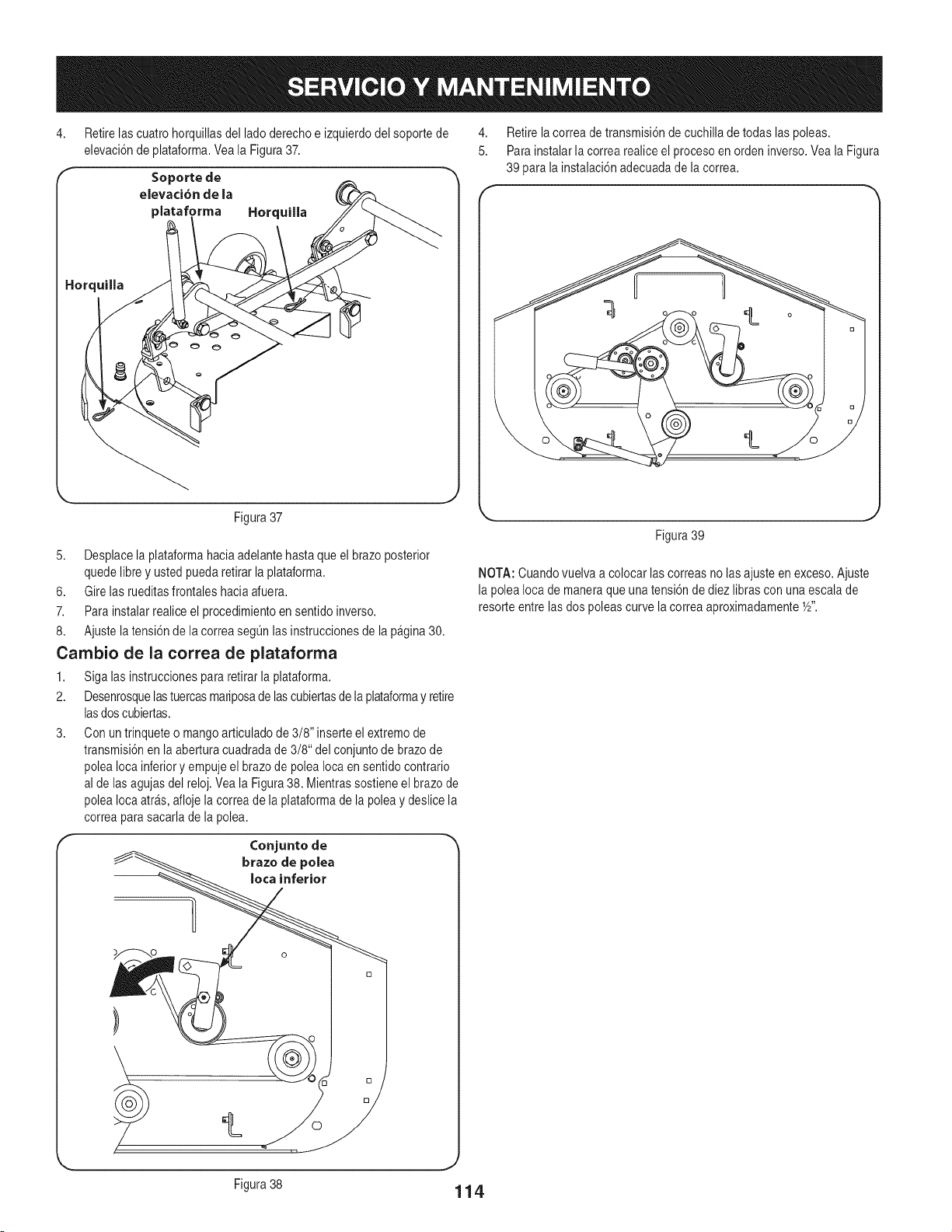
4,
Retirelascuatrohorquillasdel lado derechoe izquierdodel soporte de
elevaci6nde plataforma.Veala Figura37.
Soporte de
elevaci6n de Ja
plataforma Horquilla
Figura37
5. Desplacela plataformahaciaadelantehasta queel brazoposterior
quedelibrey ustedpuedaretirar la plataforma.
6. Gire las rueditasfrontales haciaafuera.
7. Para instalarrealiceel procedimientoen sentido inverso.
8. Ajustela tensi6n de la correasegL]nlasinstruccionesdela pagina30.
Cambio de la correa de plataforma
1. Siga las instruccionespara retirar laplataforma.
2. Desenrosquelastuercasmariposade lascubiertasde laplataformay retire
lasdoscubiertas.
3. Con un trinqueteo mangoarticuladode 3/8" inserteel extremode
transmisi6nen la aberturacuadradade 3/8" del conjuntode brazode
poleaIocainferiory empujeel brazode poleaIocaen sentidocontrario
al delas agujasdel reloj.Veala Figura38. Mientrassostieneel brazode
poleaIocaarras,afloje la correade laplataformadela poleay deslice la
correaparasacarlade la polea.
Conjunto de
brazo de polea
Iota inferior
4,
5.
Retirelacorreade transmisi6nde cuchilladetodas las poleas.
Parainstalarla correa realiceel procesoen ordeninverso.Veala Figura
39 parala instalaci6nadecuadade lacorrea.
!=
Figura39
NOTA: Cuandovuelvaa colocar lascorreasno lasajusteen exceso.Ajuste
la polea Ioca de maneraque unatensi6nde diez librascon unaescalade
1
resorte entrelas dos poleascurve lacorrea aproximadamenteY2".
Figura 38
114
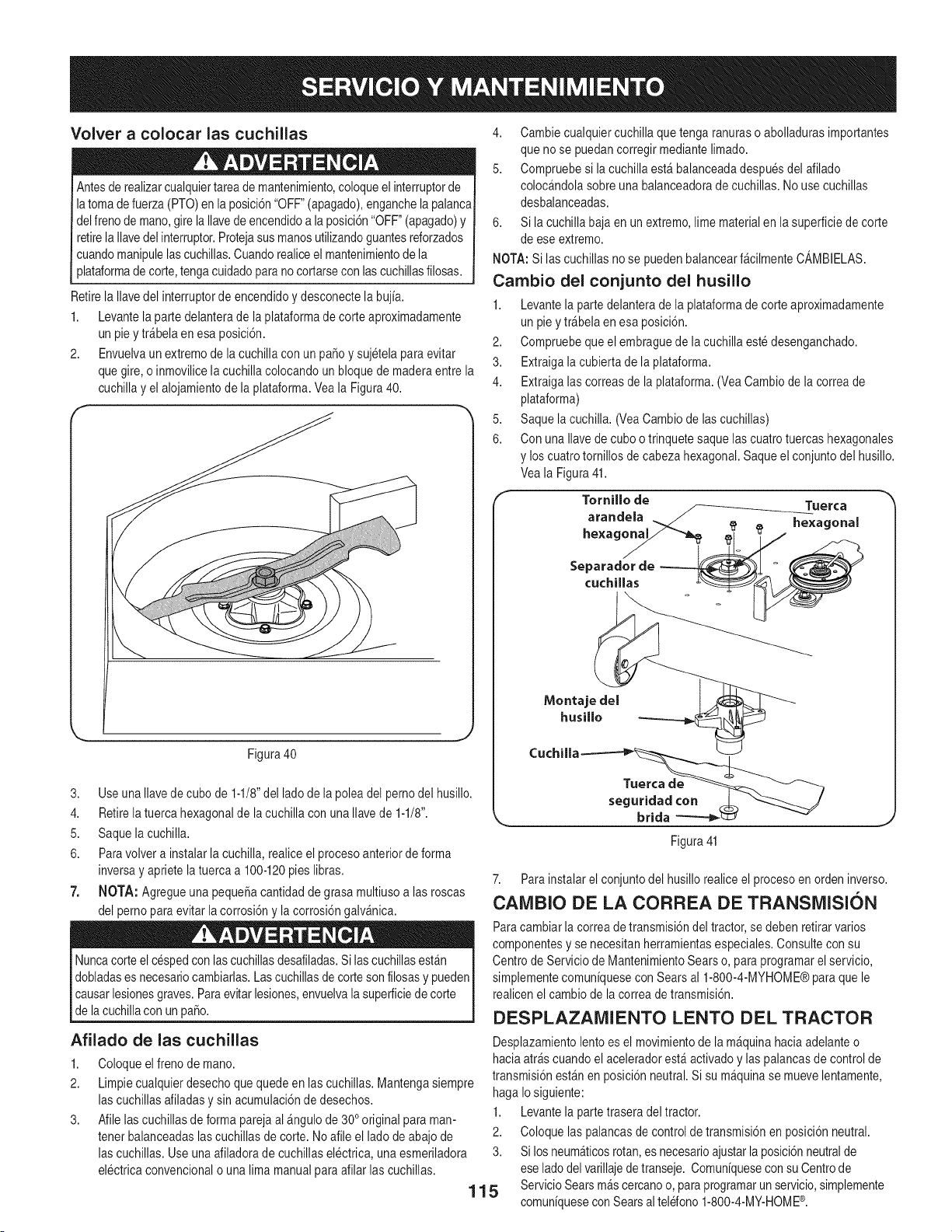
Volver a colocar las cuchillas
Antesde realizarcualquiertareade mantenimiento,coloqueel interruptorde
latoma defuerza(PTO)enla posici6n"OFF"(apagado),enganchelapalanca
delfrenode mano,gire laIlavede encendidoa la posici6n"OFF"(apagado)y
retirela Ilavedelinterruptor.Protejasusmanosutilizandoguantesreforzados
cuandomanipulelascuchillas.Cuandorealiceel mantenimientode la
plataformade corte,tengacuidadoparano cortarseconlascuchillasfilosas.
Retirela Ilavedel interruptorde encendidoy desconectela buj[a.
1. Levantela partedelanterade la plataformade corteaproximadamente
un pie y tr_belaen esa posici6n.
2. Envuelvaunextremodela cuchillacon un pasoy sujetelaparaevitar
quegire, o inmovilicela cuchillacolocandoun bloquede maderaentre la
cuchillay el alojamientode laplataforma.Veala Figura40.
Figura40
3. UseunaIlavede cubode 1-1/8"del ladode lapoleadel pernodel husillo.
4. Retirelatuerca hexagonalde lacuchilla conunaIlavede 1-1/8".
5. Saquelacuchilla.
6. Paravolvera instalarla cuchilla,realiceel procesoanteriordeforma
inversay aprietelatuercaa 100-120pies libras.
7. NOTA: Agregueuna pequeSacantidadde grasamultiusoalas roscas
del pernoparaevitar lacorrosi6ny la corrosi6ngalv_nica.
Nuncacorte elcespedconlas cuchillasdesafiladas.Si lascuchillasest_n
dobladases necesariocambiarlas.Lascuchillasde cortesonfilosasy pueden
causarlesionesgraves.Paraevitarlesiones,envuelvala superficiede corte
de la cuchillacon un paso.
Afilado de las cuchillas
1,
2.
3,
Coloqueel frenode mano.
Limpiecualquierdesechoquequedeen lascuchillas.Mantengasiempre
lascuchillasafiladasy sin acumulaci6nde desechos.
1.
Afile lascuchillasde forma parejaal &ngulode 300original paraman-
tenet balanceadaslascuchillasde corte.Noafile el ladode abajo de 2.
lascuchillas. Useunaafiladorade cuchillaselectrica,una esmeriladora 3.
electricaconvencionalo una lima manualparaafilarlas cuchillas.
115
4. Cambiecualquiercuchillaquetenga ranuras o abolladurasimportantes
que no se puedancorregir mediantelimado.
5. Compruebesi la cuchillaest_ balanceadadespuesdel afilado
colocandolasobreunabalanceadoradecuchillas.No usecuchillas
desbalanceadas.
6. Si la cuchillabajaen un extremo,lime materialen la superficiede corte
de eseextremo.
NOTA:Si lascuchillasno se puedenbalancearf_cilmenteCAMBIELAS.
Cambio del conjunto del husillo
1. Levantela partedelanterade la plataformade corteaproximadamente
un pie ytr_belaen esa posici6n.
2. Compruebequeel embraguedela cuchillaeste desenganchado.
3. Extraigala cubiertade la plataforma.
4. Extraigalas correasde laplataforma.(VeaCambiode lacorrea de
plataforma)
5. Saque la cuchilla.(VeaCambiodelascuchillas)
6. Con una Ilavedecuboo trinquete saquelas cuatrotuercas hexagonales
y los cuatrotornillosde cabezahexagonal.Saqueel conjuntodel husillo.
Veala Figura41.
Tornillo de Tuerca
arandela _//
hexago_ _ _ hexagonal
/
Separador de
cuchillas
Tuerca de
seguridad con
brida
Figura41
7. Parainstalarel conjuntodel husillorealiceel procesoen orden inverso.
CAIVlBIO DE LA CORREA DE TRANSiVlISION
Paracambiarla correadetransmisi6ndel tractor,se debenretirarvarios
componentesy se necesitanherramientasespeciales.Consultecon su
Centro de Serviciode MantenimientoSearso, para programarel servicio,
simplementecomun[quesecon Searsal 1-800-4-MYHOME®para quele
realicenel cambiode lacorreade transmisi6n.
DESPLAZAMIENTO LENTO DEL TRACTOR
Desplazamientolentoes el movimientode la m&quinahaciaadelanteo
haciaatr&scuandoel aceleradorest&activadoy las palancasdecontrol de
transmisi6nest&nen posici6nneutral.Si su m_quinase muevelentamente,
hagaIo siguiente:
Levantela partetraseradel tractor.
Coloque las palancasde controldetransmisi6nen posici6nneutral.
Si losneum&ticosrotan,es necesarioajustarla posici6nneutralde
ese lado delvarillajede transeje. Comun[quesecon su Centrode
ServicioSearsm&scercanoo, paraprogramarun servicio,simplemente
comun[quesecon Searsaltelefono1-800-4-MY-HOME®.
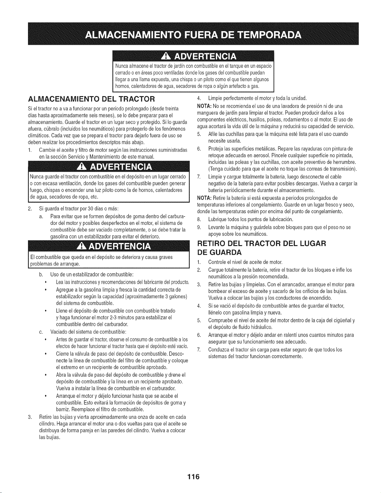
Nuncaalmaceneeltractordejardinconcombustibleeneltanqueenunespacio
cerradooen_.reaspocoventiladasdondelosgasesdelcombustiblepuedan
Ilegaraunallamaexpuesta,unachispaounpilotocomoelquetienenalgunos
hornos,calentadoresdeagua,secadoresderopaoalgOnartefactoagas.
ALMACENAMIENTO DEL TRACTOR
Si eltractor no a va a funcionarpor un periodoprolongado(desdetreinta
aliashastaaproximadamenteseis meses),se Iodebe prepararpara el
almacenamiento.Guardeeltractor en un lugarsecoy protegido.Si Io guarda
afuera,cL]bralo(incluidoslos neum_ticos)para protegerlode los fen6menos
clim_ticos.Carla vezque se preparaeltractor paradejarlofuerade uso se
debenrealizarlosprocedimientosdescriptosm_sabajo.
1. Cambieelaceitey filtro demotorsegQnlasinstruccionessuministradas
en la secci6nServicioy Mantenimientode estemanual.
Nuncaguardeel tractorcon combustibleen el dep6sitoen un lugar cerrado
o con escasaventilaci6n,dondelosgasesdel combustiblepuedengenerar
fuego,chispaso encenderuna luzpilotocomola de hornos,calentadores
de agua, secadoresde ropa,etc.
2,
Si guardaeltractor por 30aliaso m_s:
a. Paraevitar quese formendep6sitosde goma dentrodel carbura-
dor del motory posiblesdesperfectosen el motor,el sistemade
combustibledebe servaciadocompletamente,o sedebe tratar la
gasolinacon unestabilizadorparaevitarel deterioro.
Elcombustibleque quedaen el dep6sitosedeterioray causagraves
problemasde arranque.
3,
b. Usode un estabilizadorde combustible:
Lealasinstruccionesy recomendacionesdelfabricantedel producto.
,, Agreguea la gasolinalimpia y fresca la cantidadcorrectade
estabilizadorsegL]nlacapacidad(aproximadamente3 galones)
del sistemadecombustible.
,, Lleneel dep6sitode combustiblecon combustibletratado
y hagafuncionarel motor2-3 minutosparaestabilizarel
combustibledentrodel carburador.
c. Vaciadodelsistema de combustible:
, Antesde guardarel tractor,observeelconsumode combustiblea los
efectosde hacerfuncionareltractorhastaqueeldep6sitoest_vacio.
,, Cierrela v_lvulade pasodel dep6sitode combustible.Desco-
nectela linea de combustibledel filtrode combustibley coloque
el extremoen un recipientede combustibleaprobado.
,, Abra lav_lvula depasodel dep6sitode combustibleydrene el
dep6sitode combustibley la lineaen un recipienteaprobado.
Vuelvaa instalarla linea de combustibleen el carburador.
,, Arranqueel motory dejelofuncionar hastaquese acabe el
combustible.Estoevitar_ laformaci6nde dep6sitosde gomay
bamiz. Reemplaceel filtrode combustible.
Retirelasbujias y vierta aproximadamenteunaonzade aceiteen cada
cilindro.Hagaarrancarel motorunao dos vueltasparaque el aceitese
distribuyadeforma parejaen las paredesdel cilindro.Vuelvaa colocar
las bujias.
4. Limpieperfectamenteel motorytoda la unidad.
NOTA:Nose recomiendael uso de una lavadorade presi6nni de una
manguerade jardin para limpiarel tractor.PuedenproducirdaSosa los
componenteselectricos, husillos,poleas,rodamientoso al motor.Eluso de
agua acortar&lavida Qtilde la m&quinay reducir_su capacidadde servicio.
5. Afile lascuchillas paraque la m_quinaestelistapara el usocuando
necesiteusarla.
6. Protejalas superficiesmet&licas.Reparelas rayadurascon pinturade
retoqueadecuadaen aerosol.Pincelecualquiersuperficie no pintada,
incluidaslas poleasy lascuchillas,conaceitepreventivode herrumbre.
(Tengacuidadopara que elaceite notoque lascorreasde transmisi6n).
7. Limpiey carguetotalmentela bateria, luegodesconecteel cable
negativodela bateriaparaevitarposiblesdescargas.Vuelvaa cargarla
bateriaperi6dicamenteduranteel almacenamiento.
NOTA:Retirela bateriasi est_expuestaa periodosprolongadosde
temperaturasinferioresal congelamiento.Guardeen unlugarfresco y seco,
dondelas temperaturasesten porencimadel puntode congelamiento.
8. Lubriquetodoslos puntosde lubricaci6n.
9. Levantela m_quinay gu_rdelasobre bloques paraque el pesono se
apoyesobre losneum_ticos.
RETIRO DEL TRACTOR DEL LUGAR
DE GUARDA
1. Controleel niveldeaceitede motor.
2. Carguetotalmentela bateria,retire el tractorde losbloques e infle los
neum_ticosa la presi6nrecomendada.
3. Retirelas bujiasy limpielas.Con el arrancador,arranqueel motorpara
bombearel excesode aceitey sacarlode los orificiosde las bujias.
Vuelvaa colocar lasbujias y losconductoresde encendido.
4. Si se vaci6el dep6sitode combustibleantes de guardarel tractor,
Ilenelocon gasolinalimpia y nueva.
5. Compruebeel nivelde aceitedel motordentro dela caja del cig0eSaly
el dep6sitode fluido hidr_ulico.
6. Arranqueel motory dejeloandaren ralenti unoscuantosminutospara
asegurarquesu funcionamientosea adecuado.
7. Conduzcael tractorsin carga para estarsegurode quetodos los
sistemasdel tractorfuncionancorrectamente.
116
Antesde realizarcualqubrtipode mantenimientoo servbio,desenganchetodos
loscontrobsy detengael motor.Esperea quese detengancompletamente
todaslaspbzas m6vibs.Desconecteelcablede la bujiay p6ngalohacbndo
masacontraelmotorparaevitarqueseenciendaaccidentalmente.Utilice
I sbmpreanteojosdeseguddadduranteelfundonambntoo mbntrasajustao
reparaesteequipo.
En esta seeei6n se analizan problemas menores de servieio. Para ubiear el Centro de Servieio Sears m_s eereano o para programar un servieio,
simplementeeomuniquesecon Sears al tel6fono 1-800-4-MY-HOME_.
El motor no arranca 1. Perilla de toma de fuerza (PTO)/enganche
El motorfunciona de manera
erratba
de cucMla conectada.
2. Noesta colocado elfreno de mano.
3. Se ha desconectadoel cablede bujia.
4. La palancade controldel acebrador no esta
en la posM6n de arranquecorrecta.
5. El tanquede combustibleesta vac[oo el
combustiblese ha echadoa perder.
6. La I[neadel combustibleo elfiltro de combus-
tible estan tapados.
7. La bujiano funcionacorrectamente.
8. Motorahogado.
9. Fusibb(s) quemado(s).
1. La unidadestafuncionandocon el cebador
acfivado.
2. Los canes de bujiaestanflojos.
3. La lineadel combustibleesta tapada o el
combustiblese ha echadoa perder.
4. La venfilaci6nde la tapadel combustibb estA
1. Coloquela perillaen la posici6nde desconexi6n(OFF).
2. Coloqueelfreno de mano.
3. Conecteelcable a la bujia.
4. Muevala palancadel acebrador a la posid6n FAST
(VELOCIDADR,@IDA).
5,
6,
Lleneel tanquecon gasolinalimpiay nueva(de menos
de 30 dias).
Reemplacela lineadel combustible.Comuniquesecon
Searsu otro distribuidorde serviciocalificado.Reemplace
elfiltro de combustible.Vea lasecci6nde Servbio y
Mantenimiento.
7. Limpieo cambiela bujia o ajuste laseparaci6n.
8. Arranqueel motorcon el acebradoren posici6nFAST
(velocidadr@ida).
9. Cambieel fusible.
1. Compruebequeel cebadorel6ctricofuncione.Comuniquese
conSearsu otrodistribuidorde serviciocaliflcado.
2,
3.
4,
Conectey ajuste loscanes de la bujia.
Reemplacela lineadel combustible.Comuniquesecon
Searsu otro distribuidorde serviciocalificado.Lleneel
tanquecon gasolinalimpiay nuevay reemplaceel filtrode
combustible.Veala secci6nde ServMo y Mantenimbnto.
Destapelavenfilaci6no reemplacelatapa si est& daSada.
obstruida.
5. Hayaguao suciedaden el sistemade
combustible.
6. El depuradorde aireesta sucio.
5,
6,
Vacieel tanquedecombustible.Lleneel tanquecon
gasolinalimpiay nueva.Veala secci6nde Servicioy
Mantenimiento.
Limpieo reemplaceel elementode papeldel depurador
de aireo limpieel prefiltrode espuma.
NEED MORE HELP?
YOu[ :[hid/:he answer' _,£d n_oxe e£ ma_agem)/_ffeo_om _ for free!
Find this and all your other product manuals ontine.
Get answers from our team of home experts,
Get a personalized maintenance plan for your home.
find information and tools to help with home projects.
e) managemylife
117

Elmotorrecalienta
1. El nJvelde aceJtedeJmotoresta bajo
2. Flujodeairerestringido
1,
2.
Elmotorvacilaa altas revoluciones 1. Pocaseparaci6nde loselectrodosde la bujia 1.
Elmotorfuncionamal en 1. La bujia de encendidoesta sucia 1.
marchalenta 2. El depuradorde aireest_,sucio 2.
Vibraci6nexcesiva 1. Lascuchillasde corteestanflojaso desbalanceadas1.
2, Lacuchilladecorteest#,da_ada,desafiladao doblada 2.
Cortedesigual 1. La plataformanoesta correctamentenivelada. 1.
2. Cuchilladesafilada. 2.
3. Presi6nde neumaticosdesigual. 3.
Lleneel motorcon la cantidady tipo de aceiteadecuado.
Limpielos recortesdepastoy la suciedadacum@ados
alrededorde lasaletasde refrigeraci6ndel motory del
alojamientodel soplador.
Extraigala bujiay reg@ela separaci6n.
Extraigala bujiay reg@ela separaci6n.
Limpieo reemplaceel ebmento delfiRrodeaire y/o
limpieel prefiltro.
Apriete lacuchillay el husillo. Balanceela cuchilla.
Reemplacelacuchilla.
Hagaun ajustede la plataformade ladoa lado.
Afib o cambie la cuchilla.
Verifiquela presi6nde los cuatroneumaticos.
NEED MORE HELP?
o Find this and at[ your other product manua[s online.
Get answers from our team of home experts.
Get a personatized maintenance p[an for your home.
Find information and toots to he[p with home projects.
@ managemylif'e
_,_e_g_'_t _eyes 1bySea:_s
118

Felicitaciones por haber realizado una adquisici6n inteligente. El producto Craftsman® que ha
adquirido esta diseSado y fabricado para brindar muchos aSos de funcionamiento confiable. Pero
como todos los productos a veces puede requerir de reparaciones. Es en ese momento cuando el
disponer de un Acuerdo de protecci6n para reparaciones le puede ahorrar dinero y problemas.
A continuaci6n se detallan los puntos incluidos en el Acuerdo:
[] Servicio experto prestadopor nuestros 10,000 especialistas en reparacionesprofesionales
[] Servicio ilirnitado sin cargo para las piezas y la mano de obra en todas las reparacionescubiertas
[] Reernplazo del producto hasta 1500 d61aressi no es posible reparar el producto cubierto
[] Descuento de 25% del precio normal del servicio y de las piezas relacionadas con el mismo que no esten cubiertas
por el acuerdo; ademas, 25% del precio normal de laverificaci6n de mantenimientopreventivo
[] Ayuda r_pida pot tel_fono - Io IlamamosResoluci6n RApida- el apoyo telef6nico de un Chamusca al representante.
Piense en nosotros como el manual "de un dueSohablador."
Una vez adquirido el Acuerdo, puede programar el servicio con tan s61orealizar una Ilamadatelef6nica. Puede Ilamaren
cualquier momento del dia o de la noche o programar un servicio en linea.
ElAcuerdo de Protecci6nde Reparaci6nes una compra sin riesgo. Si usted anula por alguna raz6n duranteel periodo de
garantia de producto, proporcionaremos un reembolso Ileno.O, un reembolso prorrateado en cualquier momentodespues
del periodo de garantia de producto expira, iAdquiera hoy su acuerdode protecci6n para reparaciones!
Se aplican determinadas limitaciones y exclusiones. Para obtener informaciTn adicional y precios en los Estados
Unidos Ilame al 1-800-827-6655.
El *Coverage en Canad_ivaria en algunos articulos. Para detalles Ilenos la Ilamada Chamusca Canad_ien 1-800-
361-8885.
Servicio de instalaci6n de Sears
Si desea solicitar la instalaci6n profesionalde Sears de aparatos domesticos, dispositivos paraabrir portones, calentado-
res de agua y otros articulos domesticos importantes, en los Estados Unidos o Canada flame al 1-800-4-MY-HOME®.
119
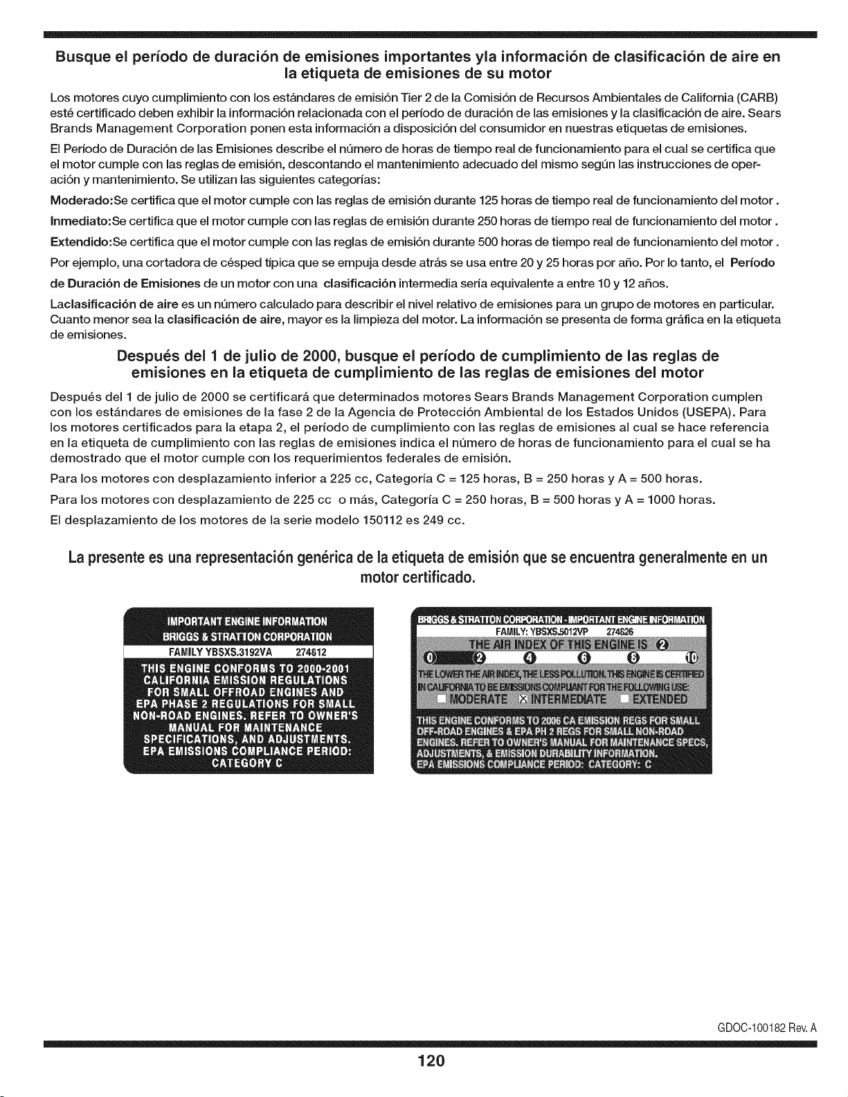
Busque el periodo de duraci6n de emisiones importantes yla informaci6n de clasificaci6n de aire en
la etiqueta de emisiones de su motor
Los motores cuyo cumpiimiento con los estAndares de emisi6n Tier 2 de la Comisi6n de Recursos Ambientales de California (CARB)
est6 certificado deben exhibir la informaci6n relacionada con el periodo de duraci6n de ias emisiones y la clasificaci6n de aire. Sears
Brands Management Corporation ponen esta informaci6n a disposici6n del consumidor en nuestras etiquetas de emisiones.
Ei Periodo de Duraci6n de las Emisiones describe el nQmero de horas de tiempo real de funcionamiento para el cuai se certifica que
el motor cumpie con ias reglas de emisi6n, descontando el mantenimiento adecuado del mismo segQn las instrucciones de oper-
aci6n y mantenimiento. Se utilizan las siguientes categonas:
Moderado:Se certifica que el motor cumpie con las reglas de emisi6n durante 125 horas de tiempo real de funcionamiento del motor.
Inmediato:Se certifica que el motor cumpie con las reglas de emisi6n durante 250 horas de tiempo real de funcionamiento del motor.
Extendido:Se certifica que el motor cumpie con las reglas de emisi6n durante 500 horas de tiempo real de funcionamiento del motor.
Por ejemplo, una cortadora de c6sped tJpica que se empuja desde arras se usa entre 20 y 25 horas por aSo. Por Io tanto, el Periodo
de Duraci6n de Emisiones de un motor con una clasificaci6n intermedia sena equivaiente a entre 10 y 12 aSos.
Laciasificaci6n de aire es un nQmero calculado para describir el nivel relativo de emisiones para un grupo de motores en particular.
Cuanto menor sea la clasificaci6n de aire, mayor es la limpieza del motor. La informaci6n se presenta de forma grAfica en la etiqueta
de emisiones.
Despu_s del 1 de julio de 2000, busque el periodo de cumplimiento de las reglas de
emisiones en la etiqueta de cumplimiento de las reglas de emisiones del motor
Despu6s del 1 de julio de 2000 se certificarA que determinados motores Sears Brands Management Corporation cumplen
con los estAndares de emisiones de la fase 2 de la Agencia de Protecci6n Ambientai de los Estados Unidos (USEPA). Para
los motores certificados para la etapa 2, el periodo de cumplimiento con ias reglas de emisiones al cual se hace referencia
en la etiqueta de cumplimiento con las reglas de emisiones indica el nQmero de horas de funcionamiento para el cual se ha
demostrado que el motor cumple con los requerimientos federales de emisi6n.
Para los motores con desplazamiento inferior a 225 cc, Categoria C = 125 horas, B = 250 horas y A = 500 horas.
Para los motores con desplazamiento de 225 cc o mAs, Categoria C = 250 horas, B = 500 horas y A = 1000 horas.
El desplazamiento de los motores de la serie modelo 150112 es 249 cc.
La presente es una representaci6n gen_rica de la etiqueta de emisi6n que se encuentra generaimente en un
motor certificado.
FAMILYYBSXS.3192VA 274812
GDOC-100182Rev.A
120
(Esta p_.ginase aplica s61oen EE.UU. y Canada.).
Sears Brands Management Corporation, el Consejo de Recursos Ambientales de California (CARB)
y la Agencia de Protecci6n Ambiental de los Estados Unidos (EPA)
Declaraci6n de garantia del sistema de control de emisiones (derechos y obligaciones de la garanfia de defectos del propi=
etario)
LA COBERTURADE LA GARANTJADE CONTROLDEEMISIONESES Y PARALOSMODELOSCERTIFICADOSDELANO 1997Y POSTERIORES,
APLIOABLEA LOSMOTORESCERTIFICADOSCOMPRADOSENCALIFOR- QUESE COMPRENY UTILICENENCUALQUIERPARTEDE LOSESTADOS
NIA EN 1995Y POSTERIORMENTE,QUESE UTILIZANENCALIFORNIA, UNIDOS(Y A PARTIRDEL 1 DE ENERODE2001 EN CANADA).
Declaraci6n de garanfia sobre defectos en el control de emisiones para California y los Estados Unidos
ElConsejode RecursosAmbientalesde California(CARB),la EPA(Agencia
de Protecci6nAmbientalde los EE.UU.)y Searstienenel gusto de explicarla
garantiadel sistemade control de emisionespara motoresdela_o 2000y para
elfuturo con relaci6na motorespeque_ostodo terreno(SORE).En California,
los nuevosmotorespeque_ostodo terrenodebenestar dise_ados,construidos
y equipadosparacumplircon las rigurosasnormasanti-smogdelestado.En
el restode los EstadosUnidos,losmotoresnuevostodoterrenode encendido
porchispacertificadosparael a_o 1997debencumplirest_ndaressimilares
establecidospot la EPA.Sears debegarantizarel sistemade control de emis-
ionesde su motorpara losperiodosde tiempo enumeradosa continuaci6n,
siemprequeno hayaabuso,negligenciao mantenimientoindebidode su
motortodoterrenopeque_o.Su sistemade controlde emisionespuedeincluir
piezastalescomoel carburador,el filtrode aire, elsistemade encendido,el
silenciadoryel conversorcatalitico.Tambienpuedeincluirconectoresy otras
unidadesrelacionadascon lasemisiones.Dondeexistaunacondici6ncubierta
por la garantia,Searsreparar_su peque6omotortodo terrenosin costoalguno
incluyendodiagn6stico,piezasy manodeobra
Cobertura de la garantJa Sears para defectos en el control de emJsiones
Los motorestodo terrenopeque6osest_ngarantizadosen Io relativoalcontrol alas disposicionesque se indiquena continuaci6n.Si una partede su motor
de emisionesparadefectosenpiezasduranteun periodode dos a_os,sujeto cubiertapot lagaranfiaes defectuosa,Sears reparar_o sustituir_dicha parte.
Responsabilidades del propietario en relacibn con la garantia
Comopropietariodel motortodo terrenopeque_o,Ud.es responsablede la
realizaci6ndel mantenimientorequeridoquese incluyeenlas instrucciones
de operaci6ny mantenimiento.Searsrecomiendaquese conserventodoslos
recibosrelativosal mantenimientodesu motortodoterrenopeque_o,pero
no pude denegarla garantiasimplementepor la faltade los mismos,o por su
incumplimientodel mantenimientoprogramatic.Comopropietariodel motor
peque_otodoterrenodebe saberque, sinembargo,Sears lepuedenegar
lacoberturade lagarantiasi su motortodoterrenopeque6oouna piezadel
mismohanfalladodebido a abuso,negligencia,mantenimientoindebidoo
a modificacionesno aprobadas.Ud.es responsablede presentarsu motor
todoterrenopeque6oa un distribuidorde serviciosSearsautorizadotan pronto
comoaparezcaun problema.Las reparacionesde la garantiasinconfiicto
debencompletarseen unplazode tiempo razonable,no superiora 30 dias.Si
tienealguna preguntarespectoa sus derechosy responsabilidadesreferen-
tes a la garantia,debe contactarcon un representantedeserviciosSearsal
1--800--469--4663.La garantiadeemisioneses unagarantiapor defectos.Los
defectosse juzgande acuerdocon elfuncionamientonormalde unmotor.La
garantiano est_relacionadaconunapruebade emisionesen uso.
Disposiciones de la garantJa Sears para defectos en el control de emJsiones
Las siguientesson disposicionesespecificasrelacionadascon la coberturade lagarantia paradefectosenel controlde emisiones.Esun a_adidoa la garantiade
motorSearspara motoresnoreguladosque seencuentraen lasinstruccionesde funcionamientoy mantenimiento.
1. Piezascon garantia
La coberturadeesta garantiase extiendeL]nicamentealas piezas
queaparecena continuaci6n(las partesde lossistemasde control de
emisiones),siempreque dichaspiezasestuvieranya enel motoren el
momentode su compra.
a. Sistemade medici6n de combustible
• Sistema de enriquecimientoparaarranqueen frio
• Carburadory partesinternas
• Bombade combustible
b. Sistemade inducci6nde aire
• Filtrode aire
• Colector de admisi6n
c. Sistemadeencendido
• Bujia(s)de encendido
• Sistema de encendidomagneto
d. Sistemadelcatalizador
• Convertidorcatalitico
• Colector de escape
• Sistema de inyecci6nde aireo v_lvulade impulsos
e. Elementosvariadosusadosenlos sistemasanteriores
• Wlvulas de vacio,sensiblesa temperatura,posici6ny tiempo
e interruptores
• Conectoresy montajes
2. AIcancede la cobertura
Searsgarantizaal poseedorinicialy a los compradoressubsiguientes
quelas piezascon garantianotendr_n defectosen materialesni mano
de obra que provoquenla falla de las mismasduranteun periodode
dos aSosa partirde la fechaen queel motorse entregaa un comprador
particular.
3. Sin cargo
La reparaci6no reemplazodecualquierpartecon garantia se realizar_
sin cargoalguno parael poseedor,incluyendotareasde diagn6sticoque
permitandeterminarsi una partecon garantiaes defectuosa,siempreque
dichodiagn6sticose realiceen un distribuidor de servicios Searsautoriza-
do. Parael serviciode lagarantia de emisiones,contacteal distribuidorde
serviciosSearsautorizadom_scercanoincluidoen las"P_ginasamarillas"
en lascategorias"Motores,gasolina","Motoresdegasolina","Podadoras
de cesped",o similares.
4. Reclamacionesyexclusionesa la cobertura
Las reclamacionesde lagarantia debenenviarsede acuerdocon las
disposicionesde la politica de garantia para motoresSears.La cobertura
de lagarantia excluir_defectosen piezascon garantia queno scan partes
originalesSears,o abuso,negligenciao mantenimientoincorrecto,tal y
como se estableceen lapolitica de garantia para motoresSears.Sears no
es responsablede lasfallas en piezas con garantia provocadaspor el uso
de partesa6adidas,que no scan originaleso quese hayan modificado.
5. Mantenimiento
Cualquierpartecon garantiaque no esteprogramadapara serreem-
plazadacomomantenimientorequerido,o que s61odebainspeccionarse
regularmentealefecto de "inspeccioneo reemplacesegL]nsea necesario",
estar_garantizadacontradefectosduranteel periodode la garantia.Todas
las piezasgarantizadasqueesten programadaspara su reemplazopara
cumplir con los requisitosde mantenimientoestar_ngarantizadass61o
por el periodoanterioral primerreemplazoprogramaticparadicha pieza.
Cualquierpiezade recambioquesea equivalenteenfuncionamientoy
durabilidadpuedeusarse para realizarmantenimientoo reparaciones.El
propietarioes responsablede realizartodoel mantenimientorequerido,tal
y comose define en las instruccionesde funcionamientoy mantenimiento
Sears
6. Coberturaindirecta
Porla presente,la coberturase extiendea la falla de cualquiercomponente
de motorprovocadapot lafalla de unapieza con garantiaque este todavia
en periodode garantia.
En los EstadosUnidosy Canad_hayunalinea de atenci6nde24 horas,1-800-469--4GG3,quecuentacon un menL]con mensajespre-grabadosque contienen
informaci6npara el mantenimientode motores.
DECLARACIONFEDERALy/oDECALIFORNIASOBRE GARANTJAS EN EL CONTROL DE EIVIISIONES
SUS DERECHOS Y OBLIGACIONES EN CUANTO A LA GARANTJA
MTDConsumerGroupInc, laAgencia de Protecci6nMedioambientalde los EstadosUnidos(EPA),y paraaquellosproductoscertificadosparasu ventaen el es-
tadode California,el Departamentode los Recursosdel Aire deCalifornia(CARB)secomplacenen explicarla garanfiaque cubre al sistemade control(ECS)de
emisiones(evaporativasy/o de escape)de su equipoy motor(motorde equipos de exteriores)de encendidopot chispaparatodo terreno,peque_o,de exteriores
del a_o2006 y a_osposterioresEn California,losnuevosmotoresde equipos de exterioresdebenestar dise_ados,construidosy equipadosparacumplircon las
estrictasnormasantipoluci6ndel Estado(en otrosestados,losequipos del a_o 1997y modelosposterioresdebenserestar dise_ados,construidosy equipados
para cumplircon las regulacionesde motoresde encendidopor chispa para todoterrenopeque_osde laAgencia de Protecci6nMedioambientalde los Estados
Unidos,(EPA).MTDConsumerGroupInc. debe garantizarel sistemade control de emisiones(ECS) de su motordeequipos de exteriorespot el periodode
tiempo indicadom_s abajo,siempreycuando no existauso incorrecto,negligenciao mantenimientoinadecuadode dicho motor.
Su ECSpuedeincluir piezastales como el carburador,el sistemade inyecci6nde combustible,el sistemade encendido,el convertidorcatalitico,los dep6sitos
de combustible,laslineas de combustible,lostaponesde combustible,lasv_lvulas, contenedores,filtros, manguerasde vapor,abrazaderas,conectoresyotros
componentesafinesrelacionadosconlasemisiones.
Dondeexista unacondici6ncubiertapor la garantia,MTDConsumerGroupInc. reparar_su motorde equiposde exterioressincosto alguno incluyendoel
diagn6stico,las piezasy la mano de obra.
COBERTURA DE LA GARANTJA DEL FABRICANTE:
Este sistemade control de emisionesse garantizaporel t@minode dos aSos.Si algunapieza relacionadacon lasemisionesde su motorde equiposde
exterioreses defectuosa,MTDCONSUMERGROUPINC.reparar_o sustituir_dicha pieza.
RESPONSABILIDADES DEL PROPIETARIO SEGUN LA GARANTJA:
En su car_cterde propietariodel motorde equipos de exteriores,usted es responsabledel mantenimientorequeridoquese especificaen el manualdel propieta-
rio.MTDConsumerGroupInc le recomiendaque conservetodos losrecibos quecubrenel mantenimientode su motor,no obstanteIo cual MTDConsumerGroup
Inc no podr_denegarel cumplimientode lagarantia Qnicamentepor la faltade los recibos.
Comopropietariodel motorde equiposde exteriores,usteddebe saber queMTDConsumerGroupInc. puededenegarlacoberturade lagarantia si su motoro
unapieza del mismofallan debido a uso incorrecto,negligencia,mantenimientoindebidoo a modificacionesno aprobadas.
Ustedes responsablede presentarsu motoral centrode distribuci6no serviciotecnico de MTDConsumerGroupInc. tan prontocomo aparezcael problema.Las
reparacionescubiertaspor la garantiase debenIlevara caboen un lapso razonableque no excedade 30 dias. Sitiene algunapreguntarespectode lacobertura
de la garantia,p6ngaseen contactoconel Departamentodel ServicioT@nicode MTDConsumerGroupInc. al telefono1-800-800-7310o pot correoelectr6nico
en http://support.mtdproducts.com
COBERTURA DE LA GARANTJA DE EMISIONES GENERALES:
MTDConsumerGroupIncgarantizaal compradorfinal y a cadacompradorsubsiguienteque el motordeequiposde exteriores:est_ dise_ado,construidoy
equipadode modo de cumplir contodas las regulacionesaplicablesy quese encuentralibre de defectosde materialesy de fabricaci6nque pudierencausar la
falla de una piezagarantizadaidentica,en todos los aspectosmaterialesa la piezadescriptaen la solicitudde certificaci6nde MTDConsumerGroupInc.
El periodode garantiacomienzaen la fechade entregadel motoral compradorfinal o en lafecha en que la m_quinase poneen funcionamientopot primeravez.
El periodode garantiaes de dos aSos.
Sujetoa ciertas condicionesyexclusionesquese indicana continuaci6n,lagarantia de las piezasrelacionadascon lasemisioneses la siguiente:
1. Cualquierpiezagarantizadaque noeste programadaparaser reemplazadacomo partedel mantenimientorequeridoen lasinstruccionesescritassuminis-
tradasse garantizaporel periodo de garantiaarriba mencionado.Sila piezafalla duranteel periodo de coberturade lagarantia, la mismaser_ reparada
o reemplazadapor MTDConsumerGroupInc. de acuerdo con el parrafo(4) a continuaci6n.Cualquierpiezareparadao reemplazadasegQnla garanfia se
garantizar_potel resto del periodode garantia.
2. Cualquierpiezagarantizadaqueeste programadasolamenteparainspecci6nregularen las instruccionesescritassuministradassegarantiza potel periodo
de garantia arribamencionado.Cualquierpiezareparadao reemplazadasegQnla garantiase garantizar_pot el restodel periodo.
3. Cualquierpiezagarantizadaqueeste programadapara reemplazosegL]nel mantenimientorequeridode conformidadcon lasinstruccionesescritassuminis-
tradas,se garantizaporel periodode tiempo anteriora laprimerafecha de reemplazoprogramadapara esa pieza.Si la piezafalla antes del primerreemplazo
programatic,la mismaser&reparadao reemplazadapot MTDConsumerGroupInc. de acuerdo con el parrafo(4) a continuaci6n.Cualquierpiezareparadao
reemplazadabajogarantia se garantizar_potel resto del periodoanterioral primerreemplazoprogramaticpuntualparaesa pieza.
4. La reparaci6no el reemplazode cualquierpiezagarantizadade conformidadcon lasdisposicionesde lagarantia queaquise estipulase deben realizarenun
centrode garantiasin costoalguno para el propietario.
5. Noobstantelas disposicionesque aquise estipulan,losservicios o reparacionesbajo garantiase suministrar_nen todos nuestroscentrosde distribuci6nbajo
franquiciademantenimientoparalos motoreso equiposen cuesti6n.
6. El propietariodel motorde equiposde exterioresno deber_pagarel trabajode diagn6sticodirectamenteasociadocon unapiezagarantizadadefectuosaen
relaci6ncon las emisiones,siemprey cuando dichotrabajode diagn6sticose realiceen un centrocubiertopot lagarantia.
7. MTDConsumerGroupInces responsablepot daSoscausadosa otros componentesde motoreso equipos derivadosde lafalla bajo garantiade cualquier
piezagarantizada.
8. Durantelatotalidaddelperiododegarantiadelmotoryequipoparatodoterrenoarribamencionado,MTDConsumerGroupIncmantendr_unsuministro
depiezasbajogarantiasuficienteparasatisfacerlademandaesperadadetalespiezas.
9. Cualquierpiezadereemplazosepodr_usarparaelcumplimientodelmantenimientoolasreparacionesbajogarantiaysesuministrar_nsincargopara
elpropietario.Dichousonoreducir_lasobligacionesdegarantiadeMTDConsumerGroupInc.
10.Nosepodr_nusarpiezasadicionalesnimodificadasquenoestenexentasdeacuerdoconelDepartamentodelosRecursosdelAire(AirResourcesBoard).
Elusodecualquierpiezaadicionalomodificadanoexentaporelcompradorfinalser_causaldeinvalidezdelosreclamosbajogaranfia.MTDConsumer
GroupIncnotendr_responsabilidadpotlagarantiadefallasdepiezasgarantizadasquefuerencausadaspotelusodeunapiezaadicionalnoexenta
omodificada.
PIEZAS GARANTIZADAS:
La reparaci6no el reemplazode cualquierpiezagarantizadaquede otto modo pudieseestar cubiertapor lagarantia podr_set excluidadetal coberturade
garantiasi MTDConsumerGroupIncdemuestraqueel motores objeto de uso incorrecto,negligenciao mantenimientoinadecuado,y que tal usoincorrecto,
negligenciao mantenimientoinadecuadofuecausa directade la necesidadde reparaci6no reemplazode dicha pieza.NoobstanteIo antedicho,cualquierajuste
de un componentecon un dispositivode limitaci6nde ajusteinstaladoen f_brica y quefuncioneadecuadamente,podr_set cubiertopot la garantia.Adem_s,
la coberturabajoesta garantiase extiendesolo a piezasqueestuvieronpresentesen el motory equipotodo terrenoadquiridos.
Est_ncubiertaslas siguientespiezascongaranfia para emisiones(decorresponder):
(1) Sistemademedici6nde combustible
• Sistemade mejorapara inicioen frio (cebadosuave)
• Carburadory piezasinternas(osistemade inyecci6npot combustible)
• Bombade combustible
• Dep6sitode combustible
(2) Sistemade inducci6nde aire
• Purificadordeaire
• Colectordeadmisi6n
(3) Sistemade encendido
• Bujia(s) deencendido
• Sistemade encendidopot magneto
(4) Sistemade encendido
• Convertidorcatalitico
,, SAI (v_lvula Reed)
(5) Componentesvariosutilizadosen el sistemaanterior
• Wlvulas e interruptoresde vacio,temperatura,posici6nsensiblesal tiempo
• Conectoresy montajes
(6) Controlevaporativo
• Manguerade combustible
• Abrazaderasde la mangueradecombustible
• Tap6ndel combustibleatadopot correa
• Cajadecarbono
• Lineas de vapor
GDOC-100223

Riding Equipment
questions or problems?
Satisfaction with your purchase
is our number one concern!
To troubleshoot problems,
get answers to questions, order parts,
or schedule repair service for your
Riding Equipment, call the number below.
Para respuestas a preguntas o problemas,
y ordenar piezas o pedir servicio para la
reparacibn de su equipo, Ilame el nt_mero abajo.
1-800-659-5917
Craftsman Help Line
www.craftsman.com
TM
® Registered Trademark / Trademark of KCD IP, LLC in the United States, or Sears Brands, LLC in other countries
® Marca Registrada / TMMarca de Fabrica de KCD IP, LLC en Estados Unidos, o Sears Brands, LLC in otros paises