Instruction manual Lawn Tractor
Tractor Preparation
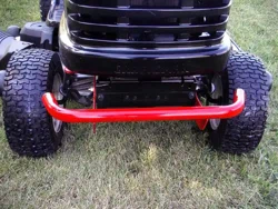
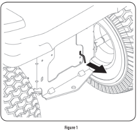
Manually Moving the Tractor
- Engage the transmission bypass rod to move the tractor manually without starting it. The transmission bypass rod is located on the rear of the tractor, on the frame. Engage the bypass rod by pulling out. See Figure 1.
NOTE: If the tractor will not move or does not move freely when pushing check if the bypass lever is fully open or the brake is engaged.
NOTE: The transmission will NOT engage when the hydrostatic bypass rod is pulled out. Return the rod to its normal position prior to operating the tractor. If the tractor will not move when pushing on the forward/reverse pedals, or moves slowly, check to see of the bypass valve is on.
- Disengage the bypass rod by pushing the rod back in after moving the tractor. See Figure 1.
Install Operator’s Seat (If necessary)
To install the seat proceed as follows:
NOTE: The seat is shipped with the seat switch and seat pan attached.
- Cut any straps securing the seat assembly to the tractor. Remove any packing material. NOTE: Be careful not to cut the wiring harness connecting the seat and the seat switch.
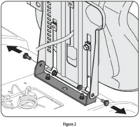
- Remove the two shoulder screws and flange lock nuts in the seat pan as shown in Figure 2.
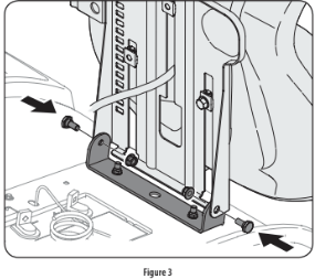
- Rotate the seat into position and secure the seat into place with the previously removed shoulder screws and flange lock nuts. Be careful not to crimp or damage the wire harness while installing the seat. See Figure 3.
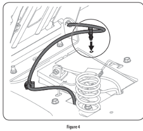
- Using the harness clip attached to the harness, secure the excess wire to the fender by snapping the harness clip in place as shown in Figure 4.
Lower Deck Discharge Chute Deflector
Check the mower deck for a shipping brace that may be holding the chute deflector upward for shipment. If the brace is present, it must be removed before operating the tractor. Holding the chute deflector fully upward, remove the shipping brace. Lower the chute deflector. See Figure 5.

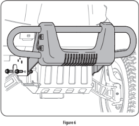
Installing the Front Bumper (If equipped)
The hardware for attaching the front bumper is shipped installed into the bumper.
- Remove the four hex screws from the bumper.
- Position the bumper brackets to the inside of the tractor’s frame and secure it in place with the four hex flange screws. See Figure 6.
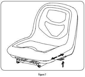
Adjusting the Seat
To adjust the position of the seat, lift the seat adjustment lever up. Slide the seat forward or rearward to the desired position; then release the adjustment lever. Make sure seat is locked into position before operating the tractor. See Figure 7.
Connecting the Battery Cables
For shipping reasons, both battery cables on your equipment may have been left disconnected from the terminals at the factory. To connect the battery cables, proceed as follows:
NOTE: The positive battery terminal is marked Pos. (+). The negative battery terminal is marked Neg. (–).
NOTE: If the positive battery cable is already attached, skip ahead to step 2.
- Remove the plastic cover, if present, from the positive battery terminal and attach the red cable to the positive battery terminal (+) with the bolt and hex nut. See Figure 8.

- Remove the plastic cover, if present, from the negative battery terminal and attach the black cable to the negative battery terminal (–) with the bolt and hex nut. See Figure 8.
- Position the red rubber boot over the positive battery terminal to help protect it from corrosion.
NOTE: If the battery is put into service after the date shown on top/side of battery, charge the battery as instructed in the Service section your Operator’s Manual prior to operating the tractor.
Setting the Deck Wheels
NOTE: The deck wheels are an anti-scalp feature of the deck and are not designed to support the weight of the cutting deck.
Move the tractor on a firm and level surface, preferably pavement, and proceed as follows:
- Check the tire pressure, make sure the pressure is correct and equal on all tires.
- Make sure the deck is level, both front-to-back and side-to-side. See the Maintenance & Adjustments section for deck leveling information and instructions.
- Select the height position of the cutting deck by placing the deck lift lever in the normally desired mowing height setting.
- Check the wheels for contact or excessive clearance with the surface below. The deck wheels should have between 1⁄4” and 1⁄2” clearance above the ground. Proceed as follows to adjust the wheels:
a. Raise the deck lift handle to its highest setting.
b. Remove the front and rear deck wheels by removing the flange lock nuts and shoulder bolts that secure them to the deck. See Figure 9.
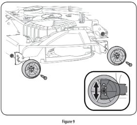
c. Place the deck lift lever in the desired mowing height setting.
d. Reinsert the shoulder bolt (with each deck wheel) into the index hole that leaves approximately 1⁄2-inch between the bottom of the wheel and the pavement. Tighten the flange lock nut and shoulder bolt to between 25-30 ft-lbs using a torque wrench.
NOTE: Refer to Adjusting the Deck in the Maintenance & Adjustments section of this manual for more detailed instructions regarding various deck adjustments.
Gas and Oil
Fuel Recommendations
Use automotive gasoline (unleaded or low leaded to minimize combustion chamber deposits) with a minimum of 87 octane. Gasoline with up to 10% ethanol or 15% MTBE (Methyl Tertiary Butyl Ether) can be used. Never use an oil/gasoline mixture or dirty gasoline. Avoid getting dirt, dust, or water in the fuel tank. DO NOT use E85 gasoline.
- Refuel in a well-ventilated area with the engine stopped. Do not smoke or allow flames or sparks in the area where the engine is refueled or where gasoline is stored.
- Do not overfill the fuel tank. After refueling, make sure the tank cap is closed properly and securely.
- Be careful not to spill fuel when refueling. Spilled fuel or fuel vapor may ignite. If any fuel is spilled, make sure the area is dry before starting the engine.
- Avoid repeated or prolonged contact with skin or breathing of vapor.
Adding Fuel
- Be sure engine is outdoors and in a well-ventilated area.
- Clean area around the fuel fill cap and remove the fuel fill cap.
- Using an approved red GASOLINE container, add fuel slowly, being careful to avoid spilling.
- Fill the tank until the fuel reaches the bottom of the fuel tank neck.
- Replace the fuel cap and tighten securely. Wipe up spilled fuel before starting engine. If fuel is spilled DO NOT start engine. Move riding mower away from area of spillage. Avoid creating any source of ignition until fuel vapors are gone.
OPERATION
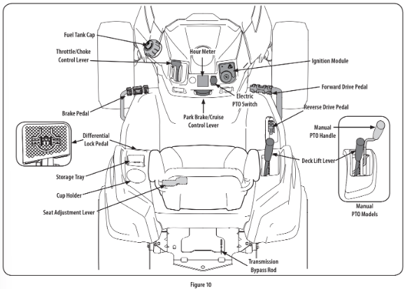
Forward Drive Pedal
The forward drive pedal is located on the right side of the machine, along the running board. Press the forward drive pedal forward to cause the tractor to travel forward. Ground speed is also controlled with the forward drive pedal. The further forward the pedal is pivoted, the faster the tractor will travel. The pedal will return to its original/neutral position when it’s not pressed.
Reverse Drive Pedal
The reverse drive pedal is located on the right side of the tractor along the running board. Ground speed is also controlled with the reverse drive pedal. The further downward the pedal is pivoted, the faster the tractor will travel. The pedal will return to its original/neutral position when it’s not pressed.
Brake Pedal
The brake pedal is located on the left side of the tractor, along the running board. The brake pedal can be used for stopping the tractor or setting the parking brake.
NOTE: The brake pedal must be fully depressed to activate the safety interlock switch when starting the tractor.
Differential Lock Pedal (if equipped)
The differential lock pedal is located on the left of the tractor to the rear of the running board near the seat box. Activating the differential lock increases traction by maintaining equal wheel speed on the rear tires. See the Differential Lock section for more information on using the differential lock.
Seat Adjustment Lever
The seat adjustment lever is located below the left of the seat. The lever allows for adjustment forward or backward of the operator’s seat. Refer to the Assembly & Set-Up section for instructions on adjusting the seat position.
Throttle/Choke Control Lever
- The throttle/choke control lever is located on the left side of the tractor’s dash panel. This lever controls the speed of the engine and, when pushed all the way forward, past the detent position closes the choke for cold starting. When set in a given position, the throttle will maintain a uniform engine speed.
- NOTE: When operating the tractor with the cutting deck engaged, be certain that the throttle/choke control is always in the FAST position.

Change Oil
The LCD will display the letters “CHG”, followed by the letters “OIL”, followed by the letters “SOON”, then finally followed by the meter’s accumulated time. “CHG/OIL/SOON/ TIME” will alternate on the display for 7 minutes after the meter reaches 50 hours. This oil service minder interval will occur every 50 hours. Before the interval expires, change the engine oil as instructed in the Maintenance section of the Engine Operator’s Manual.
Low Oil (If so equipped)
The letters “LO” followed by the letters “OIL”, then followed by the meter’s accumulated time will indicate the tractor is low on oil. When an engine is not running and immediately after the engine is started the oil pressure may be low. This can trigger the “LO” “OIL” text. This is normal. If the low oil indication persists stop the tractor immediately and check the engine oil level as instructed in the Engine Operator’s Manual.
NOTE: The “LOW OIL” function only works if the engine is equipped with an oil pressure switch.
Low Battery
At startup, the battery voltage is briefly displayed then changes to accumulated hours. The letters “LO” will display followed by the letters “BATT” and then followed by the meter’s accumulated time. “LO/BATT/TIME” is displayed on the LCD when the voltage drops below 11.5 volts. When this occurs, the battery is in need of a charge or the engine’s charging system is not generating sufficient amperage. Charge the battery as instructed in the Service section of this manual or have the charging system checked by your local service dealer.
Air Filter Service
The letters “CLN” will display, followed by the letters “AIR”, followed by “FILT”, then followed by the meter’s accumulated time. “CLN/AIR/FILT/TIME” will alternate on the display for 7 minutes after the meter reaches 50 hours. This air filter service minder time interval will be every 50 hours. On intervals that are common with oil service, the oil message will be displayed first followed by the air filter message.
Safety Interlock Switches
This tractor is equipped with a safety interlock system for the protection of the operator. If the interlock system should ever malfunction, do not operate tractor. Contact your authorized service dealer.
- The safety interlock system prevents the engine from cranking or starting unless the parking brake is engaged, and the PTO is in the DISENGAGED (OFF) position.
- The engine will automatically shut off if the operator leaves the seat before engaging the parking brake.
- The PTO clutch will automatically shut off if the operator leaves the tractor’s seat with the PTO in the ENGAGED (ON) position, regardless of whether the parking brake is engaged.
Starting the Engine
NOTE: Refer to the Assembly & Set-up section of this manual for Gasoline and Oil fill-up instructions.
- Insert the tractor key into the ignition switch module.
- Place the PTO in the disengaged (OFF) position.
- Fully engage the tractor’s brake.
- Move the throttle/choke control into the CHOKE
 position. NOTE: If the engine is warmed up, it may not be necessary to choke the engine.
- Turn the ignition key clockwise to the START
 position. After the engine starts, release the key. It will return to the NORMAL MOWING
  position.
- After the engine starts, move the throttle/choke control (if so equipped) down into the FAST
 position or push the choke control (if so equipped) down/in the OFF position.
NOTE: Do NOT leave the choke control on while operating the tractor. Doing so will result in a “rich” fuel mixture and cause the engine to run poorly and can damage the engine.
NOTE: When operating the tractor be certain that the throttle lever is always in the FAST position. Operating with the throttle at less than full throttle may lead to shortened battery life.
Engaging the Parking Brake
NOTE: The parking brake must be set if the operator leaves the seat with the engine running or the engine will automatically shut off.
To set the parking brake:
- Press the brake pedal completely down with your left foot and hold it in that position.
- Press down on the parking brake/cruise control lever and hold it in that position.
- Remove your foot from the brake pedal.
- Release pressure from the parking brake/cruise control lever.
- After completing step 3, the brake pedal should remain in the down position. If it doesn’t, the parking brake is not engaged. Repeat steps 1-4 to engage.
To disengage the parking brake, lightly press the brake pedal.
Setting The Cruise Control
To set the cruise control:
- Slowly press the forward drive pedal with your right foot until the desired speed is achieved.
- Press down on the parking brake/cruise control lever and hold it in that position.
- Remove your foot from the forward drive pedal.
- Release pressure from the parking brake/cruise control lever.
- After completing step 3, the forward drive pedal should remain in the down position and the tractor will maintain the same forward speed. If it doesn’t, the cruise control is not engaged. Repeat steps 1-4 to engage the cruise control.
To disengage the cruise control, lightly press the forward drive pedal or the brake pedal.
NOTE: Cruise control can not be set at the tractor’s fastest ground speed.
If the operator should attempt to do so, the tractor will automatically decelerate to the fastest optimal mowing ground speed.
To change the direction of travel from forward to reverse when cruise control is engaged, press the brake pedal to disengage and bring the tractor to a complete stop. Then slowly press the reverse drive pedal with the ball of your foot to travel in reverse.
Using the Deck Lift Lever
- To raise or lower the cutting deck, move the lift lever to the left, then place it in the notch best suited for your application.
Operating the Headlights
- The lamps are ON whenever the ignition key is rotated out of the STOP
 position. The lamps turn OFF when the ignition key is moved to the STOP position.
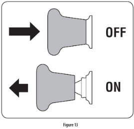
Engaging the PTO (Electric PTO tractors)
Engaging the PTO transfers power to the cutting deck or other (separately available) attachments. To engage the PTO:
- Move the throttle to the FAST position.
- Pull the PTO switch up/out into the engaged (ON) position. See Figure 13.
NOTE: When operating the tractor be certain that the throttle is always in the FAST position. Operating with the throttle at less than full throttle may lead to premature battery wear and a poor quality cut.
- To disengage the PTO, push the PTO switch down/in to the disengaged (OFF) position.
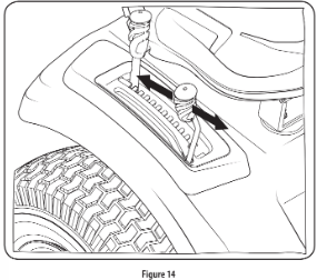
Engaging the PTO (Manual PTO tractors)
Engaging the PTO transfers power to the cutting deck or other (separately available) attachments. To engage the PTO:
- Move the throttle to the FAST position.
- Push the PTO handle forward into the engaged (ON) position. See Figure 14.
NOTE: When operating the tractor be certain that the throttle is always in the FAST position. Operating with the throttle at less than full throttle may lead to premature battery wear and a poor quality cut.
To disengage the PTO, pull the PTO handle rearward into the disengaged (OFF) position.
Mowing
NOTE: Do not engage the mower deck when lowered in grass. Premature wear and possible failure of the belt and PTO clutch will result. Fully raise the deck or move to a non-grassy area before engaging the mower deck.
- Mow up and down slopes, not across.
- Avoid turns when driving on a slope. If a turn must be made, turn down the slope. Turning up a slope greatly increases the chance of a roll over.
- Avoid stopping when driving up a slope. If it is necessary to stop while driving up a slope, start up the slope smoothly and carefully to reduce the possibility of flipping the tractor over backward
- Place the throttle into the FAST position and engage the PTO.
- Lower the mower deck to the desired height setting using the deck lift handle.
- Slowly press the forward drive pedal with your right foot until the desired speed is achieved. NOTE: The speed of the tractor will affect the quality of the mower cut. Mowing at full speed will adversely affect the cut quality. Control the ground speed with forward drive pedal.
- When approaching the other end of the strip, slow down or stop before turning.
- Align the mower with an edge of the mowed strip and overlap approximately 3”.
- Direct the tractor on each subsequent strip to align with a previously cut strip.
- To prevent rutting or grooving of the turf, if possible, change the direction that the strips are mowed by approximately 45° for the next and each subsequent mowing.
Using the Differential Lock (if equipped)
NOTE: The system should only be used when poor traction is encountered. It should be disengaged when traveling on surfaces with adequate traction.
In some instances, the tractor may be driven in slippery or low-traction situations and it may be necessary to activate the differential lock. To use the differential lock proceed as follows.
- Press down on the brake pedal to stop the motion of the tractor.
- Press down on the differential lock pedal to engage the differential lock. NOTE: The differential lock only works while the pedal is pressed.
- Release the brake pedal to drive the tractor forward while differential lock is engaged. NOTE: Engagement may be delayed. The differential lock will engage when different wheel speeds are detected. NOTE: Disengagement may be delayed. The differential lock will disengage when the rear wheel speeds allow it to release.
- To disengage the differential lock, release the differential lock pedal.
SERVICE AND MAINTENANCE
Cleaning the Underside of the Deck
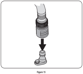
Deck Wash System: Your tractor’s deck is equipped with a water port on its surface as part of its deck wash system. Use the Smart Jet to rinse grass clippings from the deck’s underside and prevent the buildup of corrosive chemicals. Complete the following steps AFTER EACH MOWING:
1. Drive the tractor to a level, clear spot on your lawn, near enough for your garden hose to reach.
2. Disengage the PTO, set the parking brake and stop the engine.
3. Thread the hose coupler (packaged with your tractor’s Operator’s Manual) onto the end of your garden hose.
4. Attach the hose coupler to the water port on your decks surface. See Figure 15.
Note: Make sure that the hose is not routed under the deck and is clear of all moving parts.
5. Turn the water on.
6. While sitting in the operator’s position on the tractor, start the engine and place the throttle lever in the FAST position.
7. Move the tractor’s PTO into the engaged (ON) position.
8. Remain in the operator’s position with the deck engaged for a minimum of two minutes, allowing the underside of the deck to thoroughly rinse.
9. Move the tractor’s PTO into the disengaged (OFF) position.
10. Turn the ignition key to the STOP position to turn the tractor’s engine off.
11. Turn the water off and detach the hose coupler from the water port on your deck’s surface.
12. After cleaning your deck with the Smart Jet system, return to the operator’s position and engage the PTO. Keep the deck running for a minimum of two minutes, allowing the underside of the deck to thoroughly dry.
Cleaning the Tractor
Your tractor should be cleaned after each use and under certain conditions, i.e. dry conditions and/or mulching situations, additional cleaning may be necessary.
One of the best ways to keep your tractor running efficiently and to reduce fire risk is to regularly remove debris buildup from the tractor. Follow the recommendations below and contact your authorized dealer with any questions.
- Allow the machine to cool in an open area before cleaning.
- Do not use water on any part of the tractor except the underside of the cutting deck. Doing so can cause damage to the tractor’s spindle bearings, electrical system and engine, leading to premature failures. The use of compressed air and/or leaf blower will help keep the tractor clean.
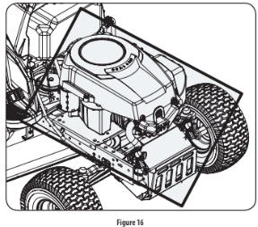
- Clean under the hood. Exhaust manifold, around fuses, all wiring and harnesses, muffler pipe, muffler shield, engine intake screens and cooling fins, etc. See Figure 16.
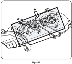
- Clean the top of the mower deck, under the spindle covers and belt area. See Figure 17.
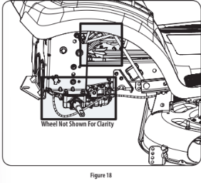
- Clean around and near the transmission, axle and the fan area. See Figure 18.
- Debris can accumulate anywhere on the tractor, especially on horizontal surfaces. Additional cleaning may be necessary when mowing in dry conditions or when mulching.
- Fuel leaks/spills, oil leaks/spills and excess lubrication can also become collection sites for debris. Immediate repair and cleaning up oil or fuel spills can help reduce fire hazards.
- In addition to cleaning the tractor before operating and storing, do not attempt to mow unusually tall grass (10” or higher), dry grass (e.g., pasture) or piles of dry leaves. Dry grass or leaves may contact the engine exhaust and/or build up on the mower deck presenting a potential fire hazard.
Storing the Tractor
- Allow the machine to cool in an open area before storing.
- Do not park the tractor near any flammable materials (wood, cloth or chemicals) or any open flames or other potential source of ignition (furnace, water heater or any other type of heater).
- Remove all combustible materials from the tractor before storing. Empty cargo boxes, grass catchers or containers.
- Always shut off fuel flow when storing or transporting if tractor is equipped with a fuel shutoff.
- Check the fuel system (lines, tank, cap and fittings) frequently for cracks or leaks. Repair and clean as necessary.
Engine
Refer to the Engine Operator’s Manual for all engine maintenance procedures and instructions for checking and adding oil. See the Changing the Engine Oil section below for oil changing procedures and instructions.
NOTE: If the “LOW OIL” text appears immediately after the engine is started the oil pressure may be low. This is normal. If the low oil indication persists stop the tractor immediately and check the engine oil level as instructed in the Engine Operator’s Manual.
NOTE: The “LOW OIL” function only works if the engine is equipped with an oil pressure switch.
Changing the Engine Oil
To complete an oil change, proceed as follows:
1. Run the engine for a short time to warm the engine oil. The oil will flow more freely and carry away more impurities. Use care to avoid burns from hot oil.
2. Locate the oil drain hose on the left side of the engine.
3. Place an appropriate oil collection container with at least a 2.5 quart capacity below the opening of the oil drain tube, to collect the used oil. Remove the oil fill cap/dipstick from the oil fill tube.
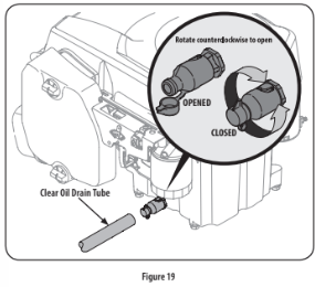
4. Pop open the protective cap on the end of the oil drain valve to expose the drain port.
5. Remove the oil fill cap/dipstick from the oil fill tube.
6. Push the clear oil drain tube (packed with this manual) onto the oil drain port. Route the opposite end of the tube into an appropriate oil collection container with at least a 2.5 quart capacity to collect the used oil.
7. The engine is equipped with a twist-and-pull drain port. Turn the oil drain valve 1⁄4-turn counter-clockwise, then pull outward to begin draining oil. After the oil has finished draining, push the end of the oil drain valve back in and turn 1⁄4-turn clockwise to secure it back in place. Re-cap the end of the oil drain valve to keep debris from entering the drain port.
8. Replace the oil filter, and refill the engine with new oil as instructed in the engine operator’s manual. NOTE: Place an absorbent towel beneath the oil filter to keep oil off the clutch.
9. To refill the oil, re-install the plug at the end of the tube and refer to the engine operator’s manual for refilling instructions, oil type and amount. NOTE : Maintenance, repair, or replacement of the emission control devices and systems which are being done at owner’s expense may be performed by any engine repair establishment or individual. Warranty repairs must be performed by an authorized dealer.
Hydrostatic Transmission
The hydrostatic transmission is sealed at the factory and is maintenance-free. The fluid level cannot be checked and the fluid cannot be changed.
Hydrostatic Neutral Adjustment
If the tractor creeps forward or rearward when neither the forward nor reverse pedal is depressed, contact your authorized dealer to have the neutral setting properly adjusted.
Cleaning the Tractor
Any fuel or oil spilled on the machine should be wiped off promptly. Do NOT allow debris to accumulate around the cooling fins of the engine, the transmission’s cooling fan or on any other part of the machine.
OFF-SEASON STORAGE
PREPARING THE ENGINE
IMPORTANT: Fuel left in the fuel tank during warm weather deterio- rates and will cause serious starting problems.
Engines stored between 30 and 90 days need to be treated with a gasoline stabilizer and engines stored over 90 days need to be drained of fuel to prevent deterioration and gum from forming in fuel system or on essential carburetor parts. If the gasoline in your engine deterio- rates during storage, you may need to have the carburetor, and other fuel system components, serviced or replaced.
To prevent gum deposits from forming inside the engine’s carburetor and causing possible malfunction of the engine, the fuel system must be either completely emptied, or the gasoline must be treated with a stabilizer to prevent deterioration.
1. If using a fuel stabilizer:
a. Read the product manufacturer’s instructions and recom- mendations.
b. Add to clean, fresh gasoline the correct amount of stabilizer for the capacity of the fuel system.
c. Fill the fuel tank with treated fuel and run the engine for 2-3 minutes to get stabilized fuel into the carburetor.
2. If emptying the fuel system:
a. Do not drain fuel when the engine is hot. Allow the engine adequate time to cool. Drain fuel into an approved container outdoors, away from open flame.
b. Drain any large volume of fuel from the tank by disconnect- ing the fuel line from the in-line fuel filter near the engine. See the complete instructions for Draining The Fuel later in this section.
c. Reconnect the fuel line and run the engine until it starts to falter, then use the choke to keep the engine running until all fuel in the carburetor has been exhausted.
d. Disconnect the fuel line and drain any remaining gasoline from the system.
3. Remove the spark plug and pour one (1) ounce of engine oil through the spark plug hole into the cylinder. Crank the engine several times to distribute the oil. Replace the spark plug.
4. Clean debris from around engine, under finger guard, and under, around and behind muffler. Touch up any damaged paint, and coat other areas that may rust with a light film of oil.
5. Store in a clean, dry and well ventilated area away from any ap- pliance that operates with a flame or pilot light, such as a furnace, water heater, or clothes dryer. Also avoid any area with a spark producing electric motor, or where power tools are operated.
6. If possible, also avoid storage areas with high humidity, because that promotes rust and corrosion.
7. Keep the engine level in storage. Tilting can cause fuel or oil leakage.
DRAINING THE FUEL
- Locate the fuel filter, which is located on the left side of the engine, and may be attached to the engine with a tie strap.
- Cut the tie strap, if present, then pinch the in-line clamp on the fuel filter with a pair of pliers, slide the clamp up the fuel line.
- Pull the fuel line free from the filter and place the open end of the line into an approved container to drain the fuel.
PREPARING THE LAWN TRACTOR
- Clean and lubricate the unit thoroughly as described in the Lubrication instructions in the Service and Maintenance section.
- Do not use a pressure washer or garden hose to clean your unit.
- Store mower in a dry, clean area. Do not store next to corrosive materials, such as fertilizer.
Removing From Storage
- Check the oil level as described in the Assembly section of this manual.
- If the fuel was drained during storage preparation, fill the tank with fresh gasoline. If you keep a container of gasoline for refueling, make certain it contains only fresh fuel. Gasoline oxidizes and deteriorates over time, causing hard starting.
- If the cylinder was coated with oil during storage preparation, the engine will smoke briefly at startup. This is normal.
TROUBLESHOOTING
Engine fails to start
1. PTO/Blade Engage knob engaged.
Place knob in disengaged (OFF) position.
2. Parking brake not engaged.
Engage parking brake.
3. Spark plug wire disconnected.
Connect wire to spark plug.
4. Throttle control lever not in correct starting position.
Place Throttle lever to FAST position.
5. Fuel tank empty, or stale fuel.
Fill tank with clean, fresh (less than 30 days old) gas.
6. Blocked fuel line.
Replace fuel line. See a qualified service dealer. Replace fuel filter. See the Service and Maintenance section.
7. Faulty spark plug.
Clean, adjust gap or replace plug.
8. Engine flooded.
Crank engine with throttle in FAST position.
9. Fuse(s) blown.
Replace fuse.
Engine runs erratically
1. Tractor running with Choke activated.
Check that the electric choke is working. See a qualified service dealer.
2. Spark plug wires loose.
Connect and tighten spark plug wires.
3. Blocked fuel line or stale fuel.
Replace fuel line. See a qualified service dealer. Fill tank with clean, fresh gasoline and replace fuel filter. See the Service and Maintenance section.
4. Vent in gas cap plugged.
Clear vent or replace cap if damaged.
5. Water or dirt in fuel system.
Drain fuel tank. Refill with clean, fresh gasoline. See the Service and Maintenance section.
6. Dirty air cleaner.
Clean or replace air cleaner paper element or clean foam pre-cleaner.
Engine overheats
1. Engine oil level low
Fill engine with proper amount and type of oil.
2. Air flow restricted
Clean grass clippings and debris from around the engine’s cooling fins and blower housing.
Engine hesitates at high RPMs
1. Spark plug gap set too close
Remove spark plug and adjust gap.
Engine idles poorly
1. Fouled spark plug
Replace spark plug and adjust gap.
2. Dirty air cleaner
Clean or replace air cleaner element and/or clean pre-cleaner.
Excessive vibration
1. Cutting blades loose or unbalanced
Tighten blade and spindle. Balance blade.
2. Damaged, dull, or bent cutting blade
Replace blade.
Mower will not mulch grass
1. Engine speed too low.
Place Throttle control in FAST (rabbit) position.
2. Wet grass.
Do not mulch when grass is wet.
3. Excessively high grass.
Mow once at a high cutting height, then mow again at desired height or make a narrower cutting swath.
4. Dull blade.
Sharpen or replace blade.
Uneven cut
1. Deck not leveled properly.
Perform side-to-side deck adjustment.
2. Dull blade.
Sharpen or replace blade.
3. Uneven tire pressure.
Check tire pressure in all four tires.