WARNING!
Before using this equipment, read the manual and follow all safety rules and operating instructions. SAVE THESE INSTRUCTIONS.
Form No. 769-19555A
(December 11, 2018)
INSTRUCTION MANUAL | MANUAL DE INSTRUCTIONES
FRONT WHEEL DRIVE MOWER
Model Nos. CMXGMAM1125501
CMXGMAM2703841
CMXGMAM1125502
CMXGMAM1125503
CMXGMAM1125504
CMXGMAM2703842
CMXGMAM7435274
IF YOU HAVE QUESTIONS OR COMMENTS, CONTACT US.
SI TIENE DUDAS O COMENTARIOS, CONTÁCTENOS.
1-888-331-4569 WWW.CRAFTSMAN.COM
NOTE: This Operator’s Manual covers several models. Features may vary by model. Not all features in this manual are applicable to all models and the model depicted may differ
from yours.
TABLE OF CONTENTS
Safety Instructions ............................................... Pages 2-5
Slope Guide ..........................................................Page 6
Unpacking ...........................................................Page 7
Assembly .........................................................Pages 7-9
Adjustments ........................................................Page 10
Operation .......................................................Pages 11-14
Service and Maintenance ........................................Pages 15-17
Off-Season Storage ..................................................Page 18
Troubleshooting ................................................. Page 19-20
Español ...........................................................Page 21

3
SAFETY INSTRUCTIONS
GENERAL OPERATION
• Read this operator’s manual carefully in its entirety before attempting to
assemble this machine. Read, understand, and follow all instructions on the
machine and in the manuals before operation. Keep this manual in a safe
place for future and regular reference and for ordering replacement parts
• Be completely familiar with the controls and the proper use of this machine
before operating it.
• This machine is a precision piece of power equipment, not a plaything.
Therefore, exercise extreme caution at all times. This machine has been
designed to perform one job: to mow grass. Do not use it for any other
purpose.
• Never allow children under 14 years of age to operate this machine. Children
14 and over should read and understand the instructions and safe operation
practices in this manual and on the machine and should be trained and
supervised by an adult.
• Only responsible individuals who are familiar with these rules of safe
operation should be allowed to use this machine.
• Thoroughly inspect the area where the equipment is to be used. Remove all
stones, sticks, wire, bones, toys and other foreign objects, which could be
tripped over or picked up and thrown by the blade. Thrown objects can cause
serious personal injury.
• Plan your mowing pattern to avoid discharge of material toward roads,
sidewalks, bystanders and the like. Also, avoid discharging material against
a wall or obstruction, which may cause discharged material to ricochet back
toward the operator.
• To help avoid blade contact or a thrown object injury, stay in operator zone
behind handles and keep children, bystanders, helpers and pets at least 75
feet from mower while it is in operation. Stop machine if anyone enters area.
• Always wear safety glasses or safety goggles during operation and while
performing an adjustment or repair to protect your eyes. Thrown objects
which ricochet can cause serious injury to the eyes.
• Wear sturdy, rough-soled work shoes and close-fitting slacks and shirts.
Shirts and pants that cover the arms and legs and steel-toed shoes are
recommended. Never operate this machine in bare feet, sandals, slippery or
light-weight (e.g. canvas) shoes.
• Do not put hands or feet near rotating parts or under the cutting deck.
Contact with blade can amputate fingers, hands, toes and feet.
• A missing or damaged discharge cover can cause blade contact or thrown
object injuries.
• Many injuries occur as a result of the mower being pulled over the foot
during a fall caused by slipping or tripping. Do not hold on to the mower if
you are falling: release the handle immediately.
• Never pull the mower back toward you while you are walking. If you must
back the mower away from a wall or obstruction first look down and behind
to avoid tripping and then follow these steps:
a. Step back from mower to fully extend your arms forward.
b. Be sure you are well balanced with sure footing.
c. Pull the mower back slowly, no more than half way toward you.
d. Repeat these steps as needed.
• Do not operate the mower while under the influence of alcohol or drugs.
• Do not engage the self-propelled mechanism on machines so equipped
while starting engine.
• The blade control handle is a safety device. Never attempt to bypass its
operation. Doing so makes the safety device inoperative and may result in
personal injury through contact with the rotating blade. The blade control
handle must operate easily in both directions and automatically return to the
disengaged position when released.
• Never operate the mower in wet grass. Always be sure of your footing. A
slip and fall can cause serious personal injury. If you feel you are losing your
footing, release the blade control handle immediately and the blade will
stop rotating within three seconds.
• Mow only in daylight or good artificial light. Walk, never run.
• Stop the blade when crossing gravel drives, walks or roads.
WARNING
This symbol points out important safety instructions which, if not
followed, could endanger the personal safety and/or property of
yourself and others. Read and follow all instructions in this manual
before attempting to operate this machine. Failure to comply with these
instructions may result in personal injury. When you see this symbol, HEED
ITS WARNING!
WARNING
CALIFORNIA PROPOSITION 65
Engine Exhaust, some of its constituents, and certain vehicle components
contain or emit chemicals known to State of California to cause cancer and
birth defects or other reproductive harm.
DANGER
This machine was built to be operated according to the safe operation
practices in this manual. As with any type of power equipment,
carelessness or error on the part of the operator can result in serious injury.
This machine is capable of amputating fingers, hands, toes and feet and
throwing debris. Failure to observe the following safety instructions could
result in serious injury or death.
WARNING
Your Responsibility—Restrict the use of this power machine to
persons who read, understand and follow the warnings and instructions in
this manual and on the machine.
SAVE THESE INSTRUCTIONS!

4
SAFETY INSTRUCTIONS
• If the equipment should start to vibrate abnormally, stop the engine and
check immediately for the cause. Vibration is generally a warning of trouble.
• Shut the engine off and wait until the blade comes to a complete stop before
removing the grass Bagger or unclogging the chute. The cutting blade
continues to rotate for a few seconds after the blade control is released.
Never place any part of the body in the blade area until you are sure the
blade has stopped rotating.
• Never operate mower without proper trail shield, discharge cover, grass
Bagger, blade control handle or other safety protective devices in place and
working. Never operate mower with damaged safety devices. Failure to do so
can result in personal injury.
• Muffler and engine become hot and can cause a burn. Do not touch.
• Never attempt to make a wheel or cutting height adjustment while the
engine is running.
• Only use parts and accessories made for this machine by the manufacturer.
Failure to do so can result in personal injury.
• When starting engine, pull cord slowly until resistance is felt, then pull
rapidly. Rapid retraction of starter cord (kickback) will pull hand and arm
toward engine faster than you can let go. Broken bones, fractures, bruises or
sprains could result.
• If situations occur which are not covered in this manual, use care and good
judgement.
SLOPE OPERATION
Slopes are a major factor related to slip and fall accidents, which can result in severe
injury. Operation on slopes requires extra caution. The machine is heavy and can
speed up when going downhill. Be prepared to maintain control of the machine.
If you feel uneasy on a slope, do not mow it. For your safety, use the slope gauge
included as part of this manual to measure slopes before operating this machine on
a sloped or hilly area. If the slope is greater than 15 degrees, do not mow it.
Do:
• Mow across the face of slopes; never up and down to avoid loss of control.
• Exercise extreme caution when changing direction on slopes; turn uphill not
down.
• Watch for holes, ruts, rocks, hidden objects, or bumps which can cause you
to slip or trip. Tall grass can hide obstacles.
• Always be sure of your footing. A slip and fall can cause serious personal
injury. If you feel you are losing your balance, release the blade control
handle immediately and the blade will stop rotating within three (3)
seconds.
Do Not:
• Do not mow near drop-offs, ditches or embankments, because you could
lose your footing or balance.
• Do not mow slopes greater than 15 degrees as shown on the slope guide.
• Do not mow on wet grass. Unstable footing could cause slipping.
CHILDREN
Tragic accidents can occur if the operator is not alert to the presence of children.
Children are often attracted to the mower and the mowing activity. They do not
understand the dangers. Never assume that children will remain where you last saw
them.
• Keep children out of the mowing area and under watchful care of a
responsible adult other than the operator.
• Be alert and turn mower off if a child enters the area.
• Before and while moving backwards, look behind and down for small
children.
• Use extreme care when approaching blind corners, doorways, shrubs, trees,
or other objects that may obscure your vision of a child who may run into the
mower.
• Keep children away from hot or running engines. They can suffer burns from
a hot muffler.
• Never allow children under 14 years of age to operate this machine. Children
14 and over should read and understand the instructions and safe operation
practices in this manual and on the machine and be trained and supervised
by an adult.
SERVICE
Safe Handling of Gasoline:
To avoid personal injury or property damage use extreme care in handling
gasoline. Gasoline is extremely flammable and the vapors are explosive.
Serious personal injury can occur when gasoline is spilled on yourself or your
clothes which can ignite. Wash your skin and change clothes immediately.
• Use only an approved gasoline container.
• Never fill containers inside a vehicle or on a truck or trailer bed with a plastic
liner. Always place containers on the ground away from your vehicle before
filling.
• Remove gas-powered equipment from the truck or trailer and refuel it on
the ground. If this is not possible, then refuel such equipment on a trailer
with a portable container, rather than from a gasoline dispenser nozzle.
• Keep the nozzle in contact with the rim of the fuel tank or container opening
at all times until fueling is complete. Do not use a nozzle lock-open device.
• Extinguish all cigarettes, cigars, pipes and other sources
of ignition.
• Never fuel machine indoors because flammable vapors will accumulate in
the area.
• Never remove gas cap or add fuel while engine is hot or running. Allow
engine to cool at least two minutes before refueling.
• Never over-fill fuel tank. To allow for expansion of the fuel, do not fill above
the bottom of the fuel tank neck.
• Replace gasoline cap and tighten securely.
• If gasoline is spilled, wipe it off the engine and equipment. Move machine to
another area. Wait 5 minutes before starting engine.

5
SAFETY INSTRUCTIONS
• Never store the machine or fuel container near an open flame, spark or pilot
light as on a water heater, space heater, furnace, clothes dryer or other gas
appliances.
• To reduce fire hazard, keep machine free of grass, leaves, or other debris
build-up. Clean up oil or fuel spillage and remove any fuel-soaked debris.
• Allow machine to cool at least 5 minutes before storing.
General Service:
• Never run an engine indoors or in a poorly ventilated area. Engine exhaust
contains carbon monoxide, an odorless and deadly gas.
• Before cleaning, repairing, or inspecting, make certain the blade and all
moving parts have stopped. Disconnect the spark plug wire and ground
against the engine to prevent unintended starting.
• Check the blade and engine mounting bolts at frequent intervals for proper
tightness. Also, visually inspect blade for damage (e.g., bent, cracked, worn).
Replace blade with the original equipment manufacture’s (O.E.M.) blade
only. Use of parts which do not meet the original equipment specifications
may lead to improper performance and compromise safety!
• Mower blades are sharp and can cut. Wrap the blade or wear gloves, and use
extra caution when servicing them.
• Keep all nuts, bolts, and screws tight to be sure the equipment is in safe
working condition.
• Never tamper with safety devices. Check their proper operation regularly.
• After striking a foreign object, stop the engine, disconnect the spark plug
wire and ground against the engine. Thoroughly inspect the mower for any
damage. Repair the damage before starting and operating the mower.
• Never attempt to make a wheel or cutting height adjustment while the
engine is running.
• Grass Bagger components, discharge cover, and trail shield are subject to
wear and damage which could expose moving parts or allow objects to be
thrown. For safety protection, frequently check components and replace
immediately with original equipment manufacturer’s (O.E.M.) parts only.
Use of parts which do not meet the original equipment specifications may
lead to improper performance and compromise safety!
• Do not change the engine’s governor setting or over-speed the engine. The
governor controls the maximum safe operating speed of the engine.
• Check fuel line, tank, cap, and fittings frequently for cracks or leaks. Replace
if necessary.
• Do not crank engine with spark plug removed.
• Maintain or replace safety and instruction labels, as necessary.
• Observe proper disposal laws and regulations. Improper disposal of fluids
and materials can harm the environment.
• According to the Consumer Products Safety Commission (CPSC) and the U.S.
Environmental Protection Agency (EPA), this product has an Average Useful
Life of seven (7) years, or 140 hours of operation. At the end of the Average
Useful Life have the machine inspected annually by a qualified service dealer
to ensure that all mechanical and safety systems are working properly and
not worn excessively. Failure to do so can result in accidents, injuries or
death.
DO NOT MODIFY ENGINE
To avoid serious injury or death, do not modify engine in any way. Tampering
with the governor setting can lead to a runaway engine and cause it to
operate at unsafe speeds. Never tamper with factory setting of engine
governor.
NOTICE REGARDING EMISSIONS
Engines which are certified to comply with California and federal EPA
emission regulations for SORE (Small Off Road Equipment) are certified
to operate on regular unleaded gasoline, and may include the following
emission control systems: Engine Modification (EM), Oxidizing Catalyst (OC),
Secondary Air Injection (SAI) and Three Way Catalyst (TWC) if so equipped.
SPARK ARRESTOR
WARNING
This machine is equipped with an internal combustion engine and should
not be used on or near any unimproved forest-covered, brushcovered or
grass-covered land unless the engine’s exhaust system is equipped with a
spark arrestor meeting applicable local or state laws (if any).
If a spark arrestor is used, it should be maintained in effective working order
by the operator. In the State of California the above is required by law (Section
4442 of the California Public Resources Code). Other states may have similar
laws. Federal laws apply on federal lands.
A spark arrestor for the muffler is available through your nearest Parts and
Repair Service Center. For location and purchase information call
1-888-331-4569.
6
SAFETY INSTRUCTIONS
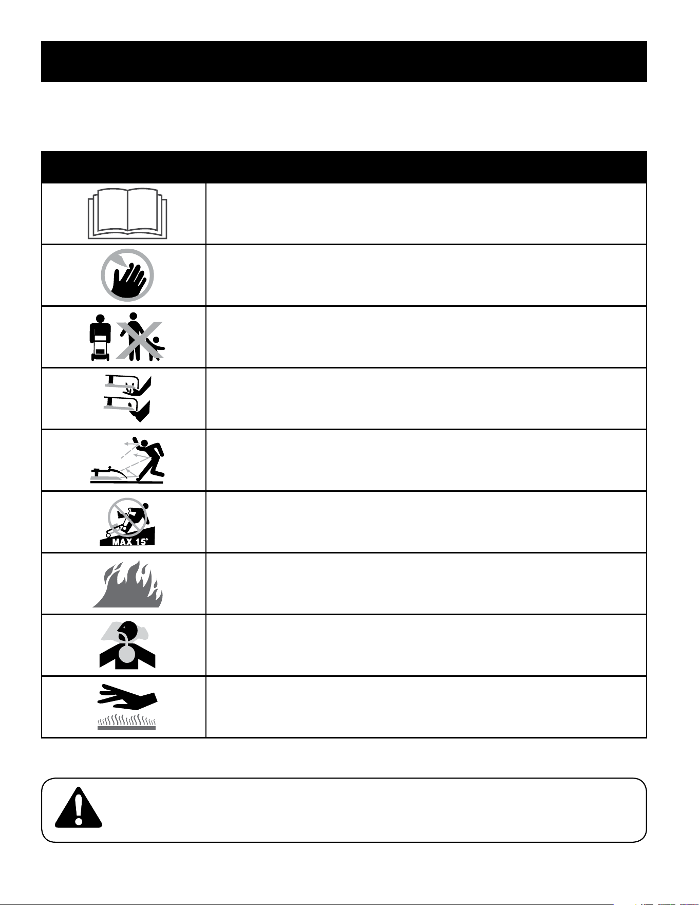
SAFETY SYMBOLS
This page depicts and describes safety symbols that may appear on this product. Read, understand, and follow all instructions on the machine before
attempting to assemble and operate.
Symbol Description
READ THE OPERATOR’S MANUAL(S)
Read, understand, and follow all instructions in the manual(s) before attempting to assemble and
operate
DANGER — ROTATING BLADES
To reduce the risk of injury, keep hands and feet away. Do not operate unless discharge cover or grass
bagger is in its proper place. If damaged, replace immediately.
DANGER — BYSTANDERS
Do not mow when children or others are around.
DANGER — HAND/ FOOT CUT
Keep hands and feet away from rotating parts.
DANGER — THROWN DEBRIS
Remove objects that can be thrown by the blade in any direction. Wear safety glasses.
DANGER — SLOPES
Use extra caution on slopes. The machine is heavy and can speed up when going downhill. Be
prepared to maintain control of the machine. To avoid loss of control, operate across slopes, not up
and down. When turning, turn uphill, not down. Do not operate on slopes greater than 15°.
WARNING—GASOLINE IS FLAMMABLE
Allow the engine to cool at least two minutes before refueling.
WARNING— CARBON MONOXIDE
Never run an engine indoors or in a poorly ventilated area. Engine exhaust contains carbon
monoxide, an odorless and deadly gas.
WARNING— HOT SURFACE
Engine parts, especially the muffler, become extremely hot during operation. Allow engine and
muffler to cool before touching.
WARNING: Your Responsibility—Restrict the use of this power machine to persons who read, understand and follow
the warnings and instructions in this manual and on the machine.
SAVE THESE INSTRUCTIONS!
7
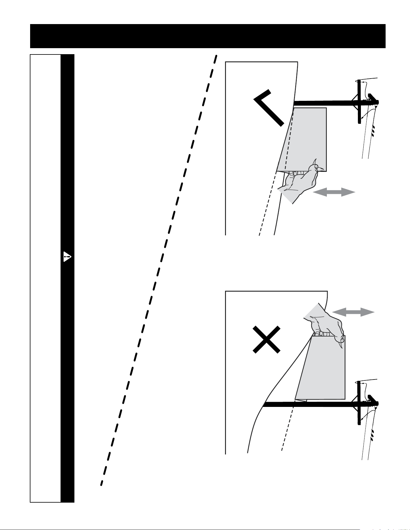
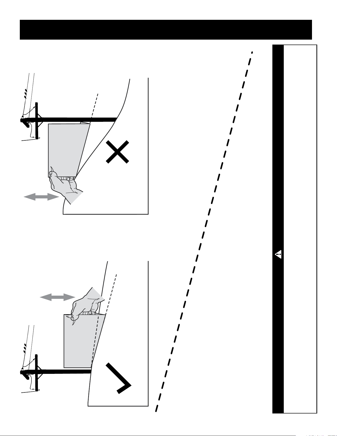
SLOPE GAUGE
(OK) (TOO STEEP)
USE THIS SLOPE GAUGE TO DETERMINE
IF A SLOPE IS TOO STEEP FOR SAFE OPERATION!
To check the slope, proceed as follows:
1. Remove this page and fold along the dashed line.
2. Locate a vertical object on or behind the slope (e.g. a pole, building, fence, tree, etc.)
3. Align either side of the slope gauge with the object (See Figure 1 and Figure 2 ).
4. Adjust gauge up or down until the left corner touches the slope (See Figure 1 and Figure 2).
5. If there is a gap below the gauge, the slope is too steep for safe operation (See Figure 2 above).
15°/25% dashed line
Slope Gauge
Figure 2Figure 1
15°/25% Slope
15°/25%
Slope
WARNING
Slopes are a major factor related to slip and fall accidents which can result in severe injury or death.
The machine is heavy and can speed up when going downhill. Be prepared to maintain control of the machine. To avoid loss of control, operate across
slopes, not up and down. When turning, turn uphill, not down. Do not operate machine on slopes in excess of 15 degrees.
7
ASSEMBLY
IMPORTANT: This unit is shipped without gasoline or oil in the engine. Be certain
to service engine with gasoline and oil as instructed in the Operation section of the
Engine Manual before starting or running your machine.
NOTE: Reference to right and left hand side of the Lawn Mower is observed from the
operating position.
Unpacking
Opening Carton
1. Cut each corner of the carton vertically from top to bottom.
2. Remove all loose parts.
3. Remove loose packing material.
Removing Unit From Carton
1. Lift unit from the rear to detach it from underlying carton material and roll
unit out of carton.
2. Check carton thoroughly for any other loose parts.
Loose Parts In Carton
• Grass Catcher
• Side Discharge Cover
• Engine Oil
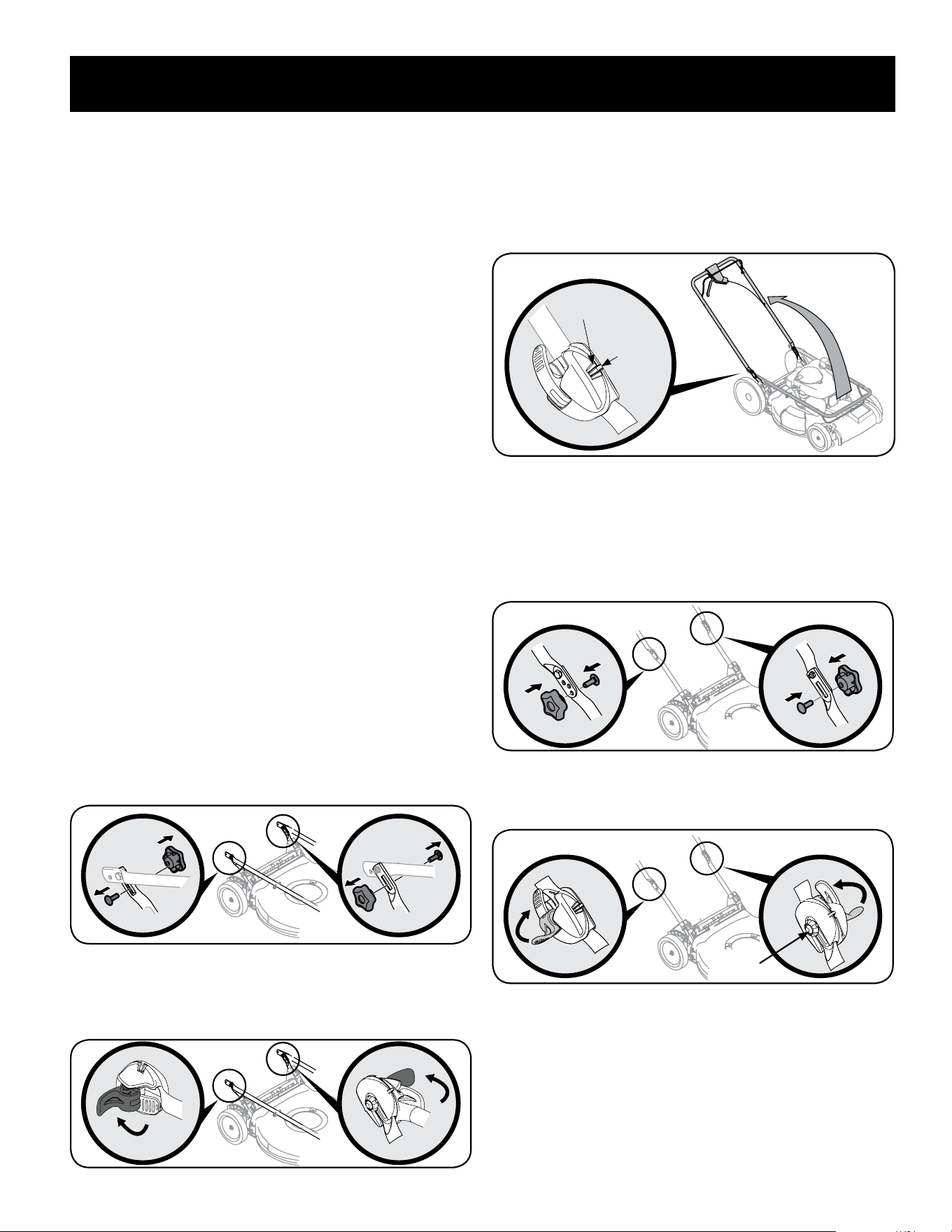
Assembly
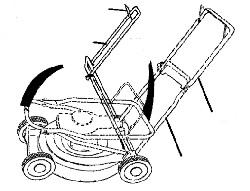
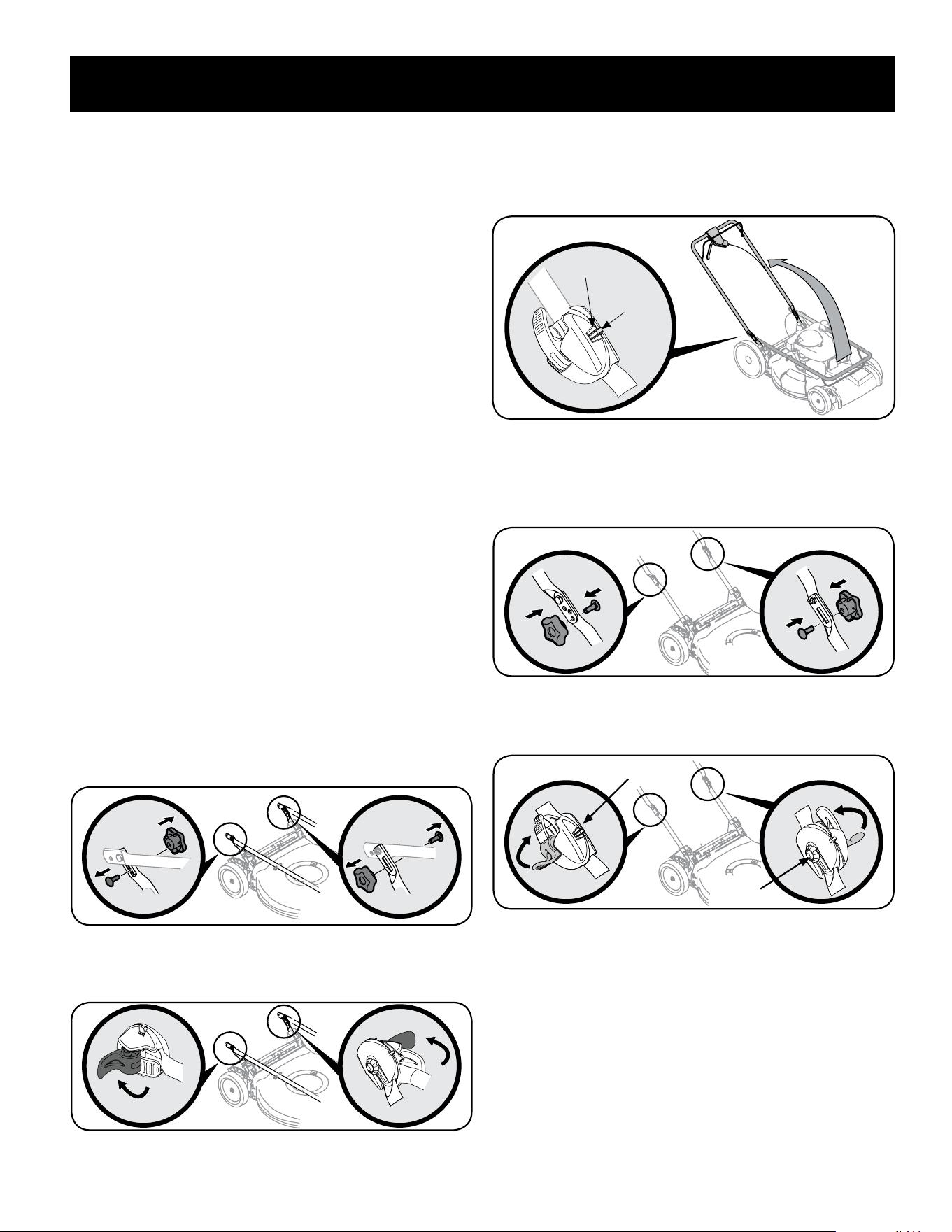
Handle Setup
1. Remove any packing material which may be between upper and lower
handles.
2. Perform one of the following according to handles shown in Figure 1 or
Figure 2:
a. Handles with Knob and Carriage Bolts - Remove knob and carriage
bolts. Do not loosen or remove adjacent hex head screws. See
Figure 1.
Figure 1
b. EZ-Fold Handles - The EZ-Fold handle release levers are shipped in
the unlocked positions. See Figure 2. Proceed to Step 3.
Figure 2
3. While stabilizing mower so it doesn’t move, lift the upper handle up as
shown in Figure 3. Do not crimp cable while lifting the handle up.
NOTE: EZ-Fold handles only - When lifting the upper handle ensure the position
indicator aligns with one of three handle positions. See Figure 3 inset.
Position
Indicator
Handle Positions
b
EZ_Fold Handle Only
Figure 3
4. Perform one of the following to secure the upper handle to the lower handle:
a. Handles with Knob and Carriage Bolts - Reattach knobs and carriage
bolts removed in Step 2a into lower holes of handle. See Figure 4.
Figure 4
b. EZ-Fold Handles - Place the release levers in the locked position. See
Figure 5.
Star Nut
Star Nut
Figure 5
8
ASSEMBLY
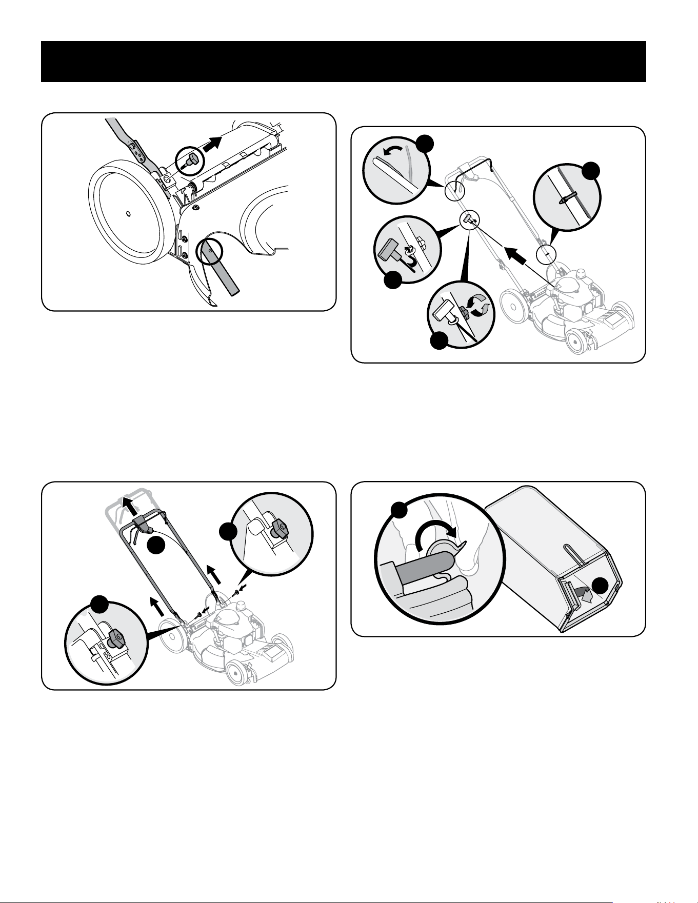
5. Remove T-bolts from the handle brackets as shown in Figure 6.
Figure 6
6. Follow the steps below to complete handle assembly:
a. Pull upward on the handle until holes in lower handle (shown in
Figure 6 deck cutaway) line up with holes in handle bracket.
See Figure 7.
NOTE: When pulling upward on handle, make sure to not pull handle all the
way out.
b. Insert the T-bolts removed in Step 2 through the handle brackets and
lower handle and tighten securely to secure the handle in place. See
Figure 7.
a
b
b
Figure 7
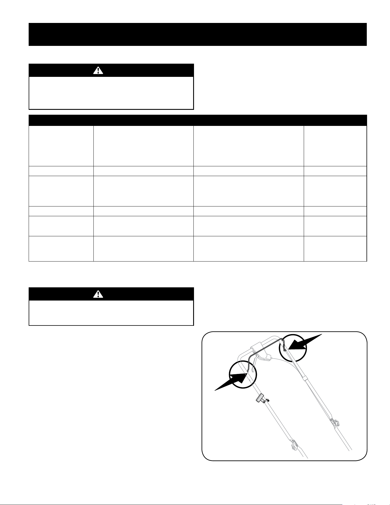
7. The rope guide is attached to the right side of the upper handle. Loosen the
wing knob which secures the rope guide. Refer to Figure 8.
a. Hold blade control against upper handle.
b. Slowly pull starter rope handle from engine and slip starter rope into
the rope guide. See Figure 8.
c. Tighten rope guide wing knob.
d. Use cable ties provided to secure blade control and drive cables to
lower handle as shown in Figure 8.
IMPORTANT: To reduce wear and allow for proper operation, make sure to
leave some slack in the upper portion of the cable(s).
d
a
b
c
Figure 8
Attaching the Grass Catcher
1. Follow steps below to assemble the grass catcher. Make certain bag is turned
right side out before assembling (warning label will be on the outside).
a. Place bag over frame so that its black plastic side is at the bottom.
b. Slip plastic channel of grass bag over hooks on the frame. See Figure 9.
a
b
Figure 9
2. Follow steps below to attach grass catcher:
a. Lift rear discharge door.
b. Place grass catcher into the slots in the handle brackets as shown
in Figure 10. Let go of discharge door so that it rests on the grass
catcher.
To remove grass catcher, lift rear discharge door on the mower. Lift grass catcher up
and off the slots in the handle brackets. Release rear discharge door to allow it to
close rear opening of mower.
9
ASSEMBLY
a
b
b
Figure 10
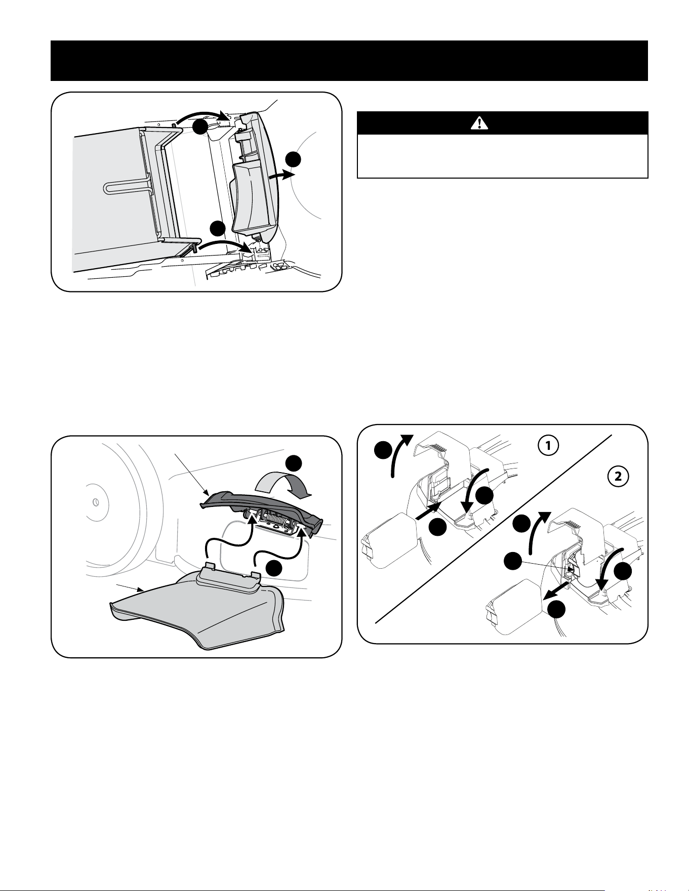
Attaching Side Discharge Cover
Your mower is shipped as a mulcher. To convert to side discharge, make sure grass
catcher is off of the unit and rear discharge door is closed.
1. On the side of the mower, lift the mulch cover. See Figure 11.
2. Slide two hooks of side discharge cover under hinge pin on mulching cover
assembly. Lower mulching cover. Do not remove side mulching cover at any
time, even when you are not mulching.
1
2
Mulch Cover
Side Discharge
Cover
Figure 11
Installing/Removing Battery Pack (if equipped)
WARNING
Read all safety warnings, instructions, and cautionary markings for the
battery pack, charger and product. Failure to follow the warnings and
instructions may result in electric shock, fire and/or serious injury.
NOTE: To ensure maximum performance and life of lithium-ion battery packs,
charge the battery fully before first use.
IMPORTANT: Refer to instructional manual supplied with battery charger for
charging, maintenance and battery disposal instructions.
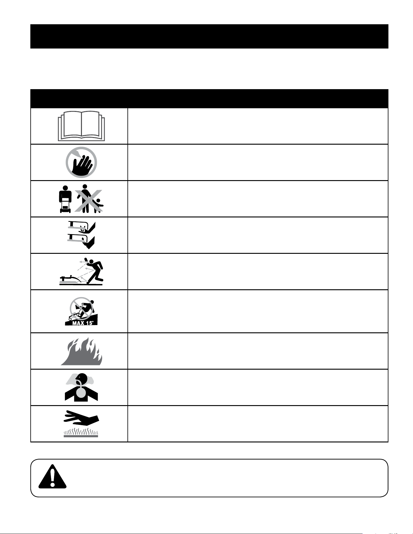
1. To install the battery pack perform the following. See Figure 12:
a. Lift the battery box cover.
b. Insert the battery pack into the battery box. An audible “click” will
be heard when the battery is properly connected.
c. Close the battery box cover.
2. To remove the battery perform the following. See Figure 12:
a. Lift the battery box cover.
b. Press the battery pack release button.
c. Pull the battery pack from the battery box.
d. Close the battery box cover.
b
c
a
d
a
b
c
Figure 12
10
ADJUSTMENTS
Adjustments
Cutting Height
There is a cutting height adjustment lever located above the front and rear right
wheel.
1. Pull the height adjustment lever outward towards wheel (unit will tend to
fall when lever is moved outward). See Figure 13.
2. Move lever to desired position for a change in cutting height. See Figure 13.
3. Release lever towards deck.
IMPORTANT: All wheels must be placed in the same position. For rough or uneven
lawns, move each height adjustment lever to a higher position. This will prevent you
from cutting the grass too close to the ground.
3
2
2
1
3
1
Lower
Lower
Higher
Higher
Figure 13
Handle Pitch (If Equipped)
For convenience of operation, you may adjust the pitch of the handle. Perform one
of the following:
1. Handles with Knobs and Carage Bolts. See Figure 14 -
a. Remove wing nuts and carriage bolts from handle.
b. Position the handle in one of the three positions that is most
comfortable. See Figure 14 inset.
c. Secure into position with wing nuts and carriage bolts removed in
Step 1.
Figure 14
2. EZ-Fold Handles. See Figure 15 -
a. Place the release levers in the unlocked positions.
b. Move the upper handle to align the position indicator with the most
comfortable of the three handle positions.
c. Place the release levers in the locked positions.
a
c
b
Position Indicator
Handle Positions
Figure 15
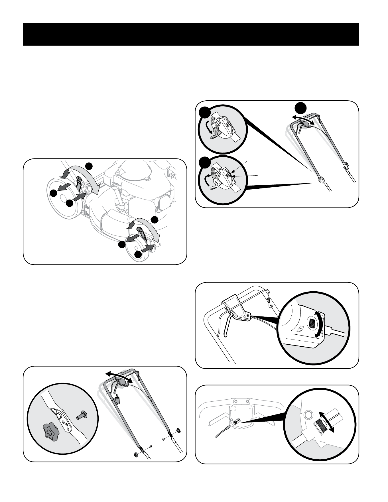
Drive Control (If Equipped)
The adjustment wheel is located in the drive control handle housing and is used
to tighten or loosen the drive belt. You will need to adjust the drive control if the
mower does not propel itself with the drive control engaged or if the mower’s
wheels hesitate with the drive control engaged. If either of these conditions occur,
rotate adjustment wheel clockwise to tighten cable or counterclockwise to loosen
the cable. See Figure 16 or Figure 17.
Tighten
Loosen
Figure 16
Tighten
Loosen
Figure 17
11
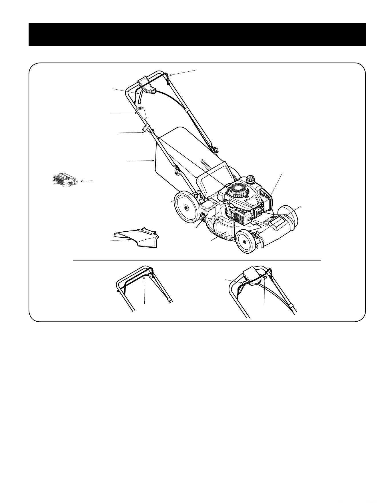
OPERATION
Blade Control
Recoil Starter
Grass Catcher*
Deck Wash*
Cutting Height
Adjustment
Lever
Cutting Height
Adjustment
Lever
Side Discharge
Chute*
Drive Control*
Electric Starter
Push Key*
Mulch Plug*
Battery Charger*
* If Equipped
Drive Control*
Drive
Control*
Drive
Control*
Figure 18
Battery Box

12
OPERATION
Blade Control
The blade control is attached to the upper handle of the mower. Depress and
squeeze it against the upper handle to operate the unit. Release it to stop engine
and blade.
WARNING
This blade control is a safety device. Never attempt to bypass its operation.
Drive Control - Bail or Single Lever (If Equipped)
The drive control is located on top of the upper handle and is used to engage the
drive. Squeeze it against the upper handle to engage the drive; release it to slow
down or stop mower from propelling.
Drive Control - Dual Lever (If Equipped)
The drive controls are located on top of the upper handle and are used to engage
the drive. Squeeze the right, left, or both right and left controls against the upper
handle to engage the drive; release it/them to slow down or stop mower from
propelling.
Electric Starter Push Key (If Equipped)
The electric starter push key is located on the right side of the upper handle. It is
both a removable key and push button and is only provided on electric start models.
Cutting Height Adjustment Lever
One adjustment lever is located on the right rear wheel and one is located on the
right front wheel. Both levers have to be at the same position to ensure a uniform
cut. To adjust the cutting height, refer to the Assembly Section.
Side Discharge Cover (If Equipped)
Your mower is shipped as a mulcher. To discharge the grass clippings to the side
instead, follow the instructions in the Assembly section to attach the side discharge
cover.
WARNING
Keep hands and feet away from the chute area on cutting deck. Refer to
warning label on the unit.
Grass Catcher (If Equipped)
The grass catcher, located at the rear of the mower, is used to bag the grass
clippings for disposal at another site. Once the bag is full, remove it up through the
handles and empty it before any further mowing.
Mulch Cover (If Equipped)
The mulch cover is used for mulching purposes. Instead of collecting the grass
clippings in a grass catcher or using the side discharge chute, some mower models
have the option of recirculating the clippings back to the lawn. This is called
mulching.
Trail Shield (If Equipped)
The trail shield is attached to the rear of the mower and is there to protect the
operator from flying debris. Do not use the mower unless the shield is fully
functional and in place.
Deck Wash (If Equipped)
Your mower’s deck is equipped with a water port on its surface as part of its deck
wash system. Use the deck wash to rinse grass clippings from the deck’s underside.
Recoil Starter
The recoil starter is attached to the right upper handle. Stand behind the unit and
pull the recoil starter rope to start the unit.
Oil Fill Cap/Dipstick
Refer to the Engine Operator’s Manual packed with your mower for detailed oil
filling, checking and changing instructions.
Meets ANSI Safety Standards
Craftsman Lawn Mowers conform to the safety standard of the American National Standards Institute (ANSI).
13
OPERATION
GAS AND OIL FILL-UP
WARNING
Use extreme care when handling gasoline. Gasoline is extremely
flammable and the vapors are explosive. Never fuel the machine indoors or
while the engine is hot or running. Extinguish cigarettes, cigars, pipes and
other sources of ignition.
IMPORTANT: Refer to the separate Engine Operator’s Manual for additional engine
information.
This unit is shipped without gasoline or oil in the engine. Be certain to service
engine with gasoline and oil as instructed before starting or running your lawn
mower.
1. Add provided oil before starting mower for the first time as instructed in the
separate Engine Operator’s Manual.
2. Service the engine with gasoline as instructed in the separate Engine
Operator’s Manual.
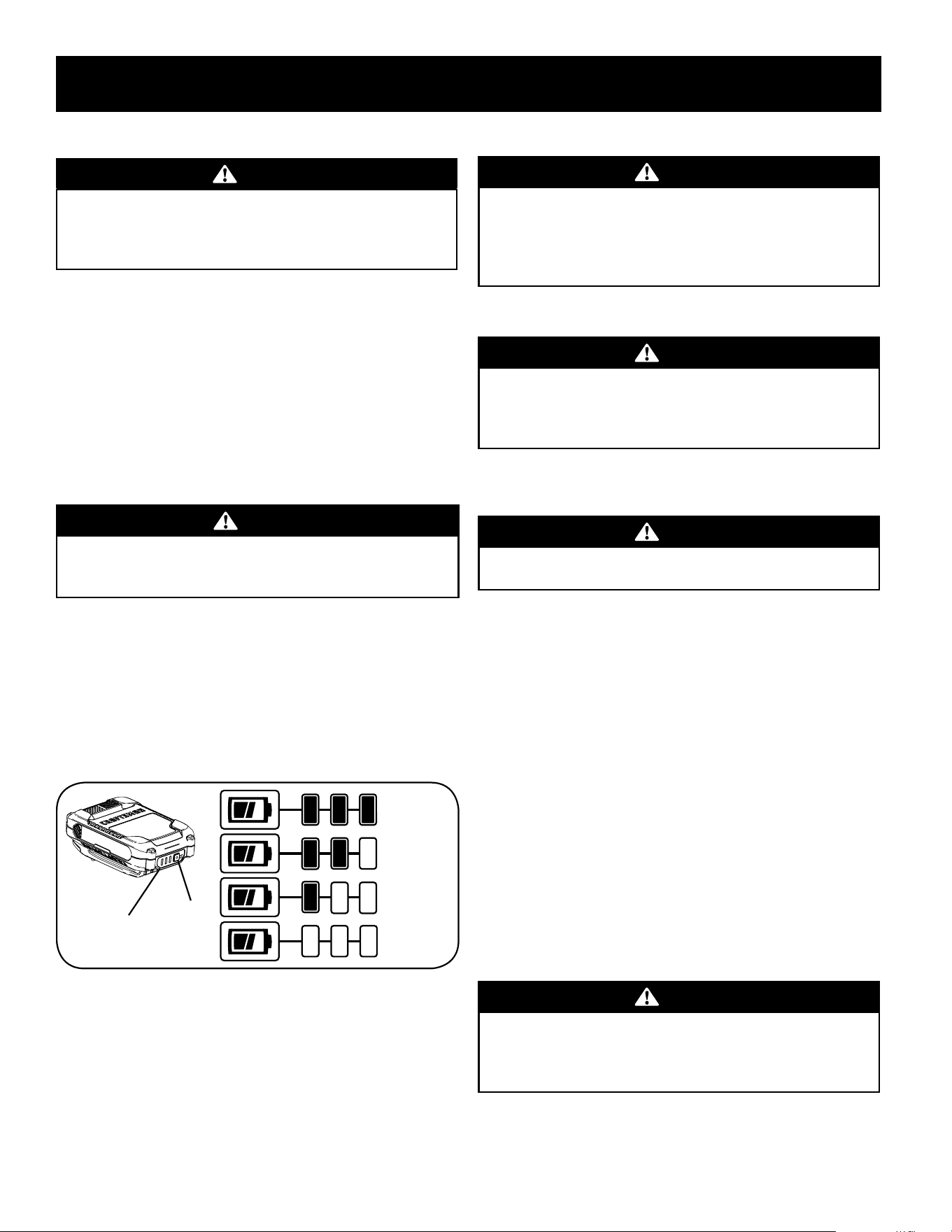
Checking Battery Pack Charge (if equipped)
WARNING
Read all safety warnings, instructions, and cautionary markings for the
battery pack, charger and product. Failure to follow the warnings and
instructions may result in electric shock, fire and/or serious injury.
IMPORTANT: Refer to instructional manual supplied with battery charger for
charging, maintenance and battery disposal instructions.
1. Press the battery gauge button on front of the battery pack to check charge
level. See Figure 19:
• Charged Battery - One to three lights of the battery gauge will light to show
charge level.
• Discharged Battery - If no lights show, charge battery pack. Refer to manual
supplied with battery charger for charging instructions.
Full Charge
No Charge
Battery
Gauge
Battery
Gauge
Button
Figure 19
To Start Engine
WARNING
Be sure no one other than the operator is standing near the lawn mower
while starting engine or operating mower. Never run engine indoors or
in enclosed, poorly ventilated areas. Engine exhaust contains carbon
monoxide, an odorless and deadly gas. Keep hands, feet, hair and loose
clothing away from any moving parts on engine and lawn mower.
Refer to the Engine Operator’s Manual for instructions on starting and stopping the
engine.
WARNING
Keep a firm grip on the starter cord handle to prevent rapid retraction of
starter cord (kickback). Rapid retraction can pull hand and arm toward
engine faster than you can let go, and result in broken bones, fractures,
bruises or sprains.
To Stop Engine
1. Release blade control to stop the engine and blade.
WARNING
Wait for the blade to stop completely before performing any work on the
mower or to remove the grass catcher.
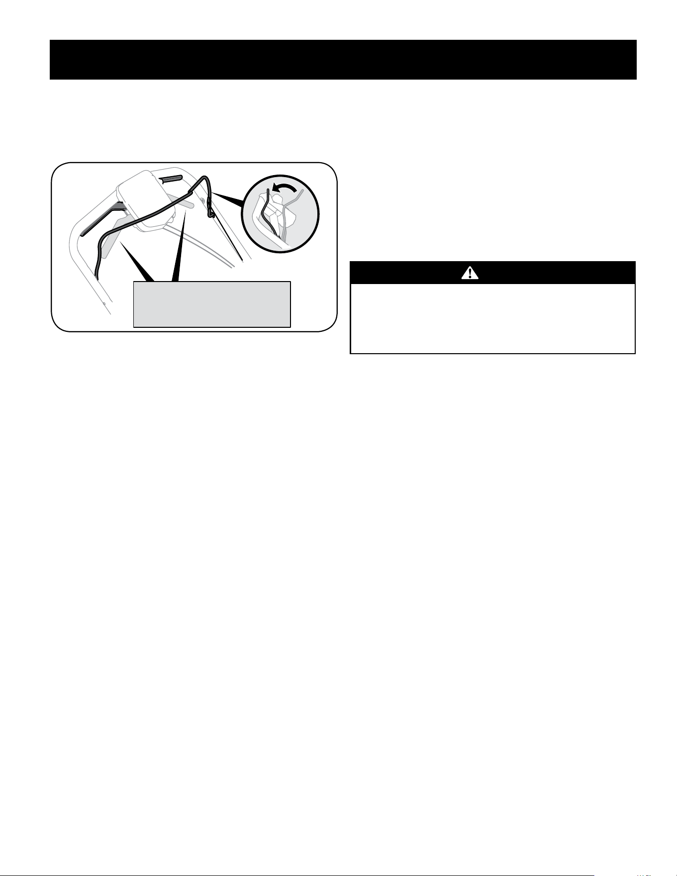
Using Your Lawn Mower
Be sure lawn is clear of stones, sticks, wire, or other objects which could damage
lawn mower or engine. Such objects could be accidently thrown by the mower in
any direction and cause serious personal injury to the operator and others.
1. Perform one of the following:
• Bail and Single Lever Drive Controls - Once the engine is running, squeeze the
drive control against the upper handle to propel mower.
• Dual Lever Drive Controls -
a. Once the engine is running and while continuing to hold the blade
control down, squeeze either (or both) drive controls against the
upper handle to propel mower. See Figure 20.
b. To change speed, move speed control to the desired speed.
NOTE: When selecting a drive speed, use the first speed until you are
comfortable and familiar with the operation of the mower.
IMPORTANT: If you are shifting speeds while the mower is stationary it may
be difficult to shift into first speed under certain conditions. This is easily
remedied by briefly engaging the drive lever.
WARNING
The operation of any lawn mower can result in foreign objects being
thrown into the eyes, which can damage your eyes severely. Always
wear safety glasses while operating the mower, or while performing any
adjustments or repairs on it.
14
OPERATION
NOTE: Your mower is equipped with an advanced internal drive system for ease of
use. When turning or pulling the unit rearward, you may notice higher than normal
resistance in the rear wheels under certain conditions. This is perfectly normal
and can be remedied by allowing the unit to roll forward slightly without the drive
lever(s) engaged before pulling backwards.
Engage the right, the left, or
both the right and left control
levers to propel the mower.
Figure 20
Using as Mulcher
For mulching grass, remove the grass catcher or side discharge chute from the
mower. When you remove the grass catcher from the mower, ensure the rear
mulch plug (if equipped) is installed and allow the rear discharge door to close the
rear opening of mower. When you remove the side discharge chute, the mulching
cover will close. For effective mulching, do not cut wet grass. If the grass has been
allowed to grow in excess of four inches, mulching is not recommended. Use the
grass catcher to bag clippings instead.
Using Grass Catcher (If Equipped)
You can use the grass catcher to collect clippings while you are operating the
mower.
1. Attach grass catcher following instructions in the Assembly section. Grass
clippings will automatically collect in bag as you run mower. Operate mower
until grass bag is full.
2. Stop engine completely by releasing the blade control. Make sure that the
unit has come to a complete stop.
3. Lift discharge door and pull grass bag up and away from the mower to
remove the bag. Dispose of the grass clippings and reinstall the bag when
complete.
WARNING
If you strike a foreign object, stop the engine. Disconnect the spark plug
wire, thoroughly inspect mower for any damage, and repair damage
before restarting and operating. Extensive vibration of mower during
operation is an indication of damage. The unit should be promptly
inspected and repaired.
15
SERVICE AND MAINTENANCE
WARNING
Before performing any type of maintenance/service, disengage all controls
and stop the engine. Wait until all moving parts have come to a complete
stop. Disconnect spark plug wire and ground it against the engine to
prevent unintended starting.
Follow the maintenance schedule given below. This chart describes service
guidelines only. Use the Service Log column to keep track of completed
maintenance tasks. To locate the nearest Service Center or to schedule service, call
the following toll free number:1-888-331-4569.
See the Engine Operator’s manual packed with the mower for detailed instructions
on how to perform many of the following maintenance items.
MAINTENANCE SCHEDULE
Interval Item Service Service Log
Each Use 1. Engine oil level
2. Loose or missing hardware
3. Air cleaner
4. Unit and engine
1. Check
2. Tighten or replace
3. Check
4. Clean
1st Month or 5 hours 1. Engine oil 1. Change
Annually or 25 hours 1. Air cleaner *
2. Control linkages/pivots and wheels
3. Underside of mower deck
1. Clean
2. Lube with light oil
3. Clean
Annually or 50 hours 1. Engine oil 1. Change
Annually 1. Spark plug
2. Air Cleaner
1. Replace
2. Replace
Before Storage 1. Fuel system 1. Run engine until it stops from lack of fuel, or
add stabilizer to a full tank of fresh fuel prior
to storage.
* Clean more often under dusty conditions or when airborne debris is present. Replace air cleaner if very dirty.
WARNING
Always stop engine, allow engine to cool, disconnect spark plug wire, and
ground against engine before performing any type of maintenance on your
machine.
General Recommendations
• Always observe safety rules when performing any maintenance.
• The warranty on this lawn mower does not cover items that have been
subjected to operator abuse or negligence. To receive full value from
warranty, operator must maintain the equipment as
instructed here.
• Changing of engine-governed speed will void engine warranty.
• All adjustments should be checked at least once each season.
• Periodically check all fasteners and make sure these are tight.
Lubrication
Blade Control
Lubricate pivot points on the blade control at least once a season with light oil. This
control must operate freely in both directions. See Figure 21.
Figure 21
16
SERVICE AND MAINTENANCE
Engine Maintenance
Refer to the Engine Operator’s Manual packed with your mower for a detailed
description of all engine-related service specifications.
Clean Engine
• Daily or before every use, clean grass, chaff or accumulated debris from
engine. Keep linkage, spring, and controls clean. Keep area around and
behind muffler free of any combustible debris.
• Keeping engine clean allows air movement around engine.
• Engine parts should be kept clean to reduce the risk of overheating and
ignition of accumulated debris.
CAUTION
Do not use water to clean engine parts. Water could contaminate fuel
system. Use a brush or dry cloth.
Mower Maintenance
Cleaning Deck
Clean underside of the mower deck once a season to prevent build-up of grass
clippings or other debris. Follow steps below for this job.
1. Allow the engine to run until it is out of fuel. Do not attempt to pour fuel
from the engine. Disconnect spark plug wire. Refer to Engine Operator’s
Manual.
2. Tip mower so that it rests on the housing, keeping the muffler side down.
Hold mower firmly.
WARNING
Never tip the mower more than 90º in any direction and do not leave the
mower tipped for any length of time. Oil can drain into the upper part of
the engine causing a starting problem.
3. Scrape and clean the underside of the deck with a suitable tool. Do not spray
with water.
IMPORTANT: Do not use a pressure washer or garden hose to clean your unit.
These may cause damage to bearings, or the engine. The use of water will
result in shortened life and reduce serviceability.
4. Put the mower back on its wheels on the ground.
Deck Wash (If Equipped)
Your mower’s deck is equipped with a water port on its surface as part of its deck
wash system.
Use the deck wash to rinse grass clippings from the deck’s underside and prevent
the buildup of corrosive chemicals. Complete the following steps AFTER EACH
MOWING:
1. Push the mower to a level, clear location on your lawn, near enough for your
garden hose to reach. Remove the grass bag if attached.
CAUTION
Make certain the mower’s discharge chute is directed AWAY from your
house, garage, parked cars, etc.
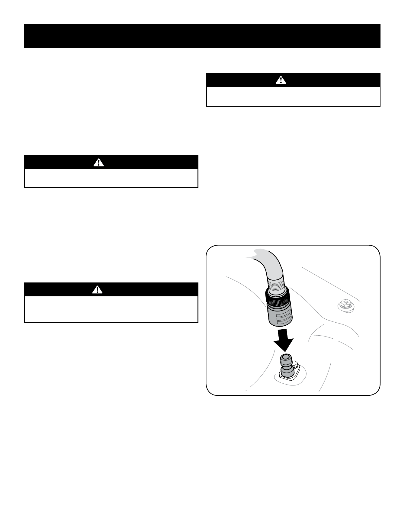
2. Remove the fast attach deck wash nozzle from the mower deck and thread it
onto the end of your garden hose.
3. Attach garden hose with the deck wash nozzle to the water port on your
deck’s surface. See Figure 22.
4. Turn the water ON.
5. Start the engine as described in the Operation section.
6. Run the engine for a minimum of two minutes, allowing the underside of the
cutting deck to thoroughly rinse.
7. Release blade control to stop the engine and blade.
8. Turn the water OFF and detach the deck wash nozzle from the water port on
your deck’s surface.
After cleaning your deck, restart the mower. Keep the engine and blade running
for a minimum of two minutes, allowing the underside of the cutting deck to
thoroughly dry
.
Figure 22
17
SERVICE AND MAINTENANCE
Blade Care
WARNING
When removing the cutting blade for sharpening or replacement, protect
your hands with a pair of heavy gloves or use a heavy rag to hold the blade.
Periodically inspect the blade adapter for cracks, especially if you strike a foreign
object. Replace when necessary. Follow the steps below for blade service.
1. Allow the engine to run until it is out of fuel. Do not attempt to pour fuel
from the engine. Disconnect spark plug wire. Refer to Engine Operator’s
Manual.
2. Turn mower on its side making sure that the air filter and the carburetor are
facing up.
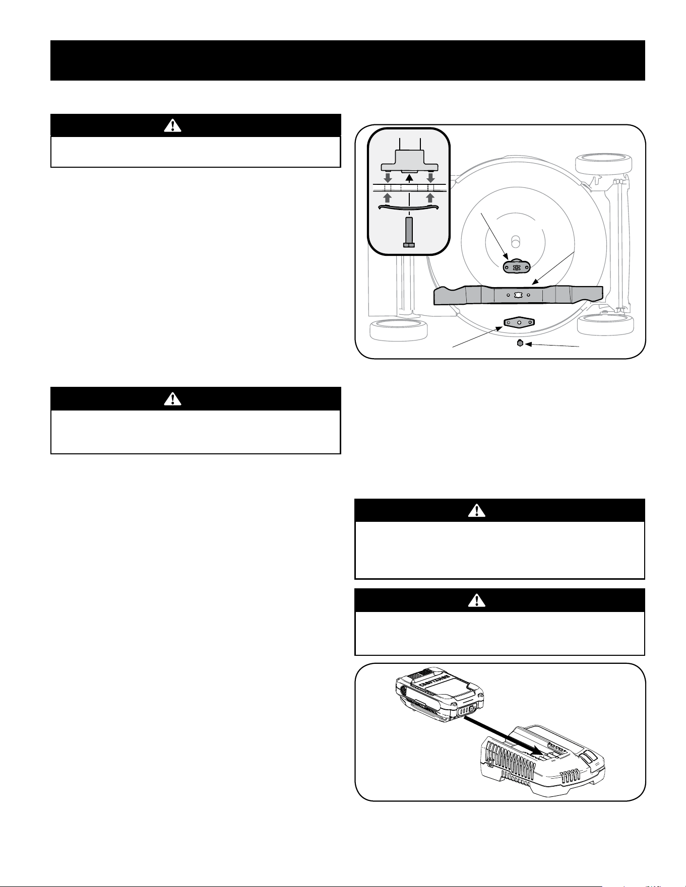
3. Remove the bolt and the blade bell support which hold the blade and the
blade adapter to the engine crankshaft. See Figure 23.
4. Remove blade and adapter from the crankshaft.
5. Remove blade from the adapter for testing balance. Balance the blade on a
round shaft screwdriver to check. Remove metal from the heavy side until
it balances evenly. When sharpening the blade, follow the original angle of
grind. Grind each cutting edge equally to keep the blade balanced.
WARNING
An unbalanced blade will cause excessive vibration when rotating at high
speeds. It may cause damage to mower and could break causing personal
injury.
6. Lubricate the engine crankshaft and the inner surface of the blade adapter
with light oil. Slide the blade adapter onto the engine crankshaft. Place the
blade on the adapter such that the side of the blade marked “Grass Side”
(or with part number) faces the ground when the mower is in the operating
position. Make sure that the blade is aligned and seated on the blade adapter
flanges. See Figure 23 inset.
7. Place blade bell support on the blade. Align notches on the blade bell
support with small holes in blade.
8. Replace hex bolt and tighten hex bolt to torque:
450 in-lb (min.), 600 in-lb (max.).
To ensure safe operation of your mower, periodically check the blade bolt for correct
torque.
Blade
Blade
Adapter
Bolt
Blade Bell Support
Figure 23
Belt Care
NOTE: Several components must be removed in order to change the mower’s self-
propulsion drive belt. See an authorized Service Center to have your belt replaced.
Charging Electric Starter Battery (If Equipped)
IMPORTANT: Refer to instructional manual supplied with battery charger for
charging, maintenance and battery disposal instructions.
WARNING
The battery contains corrosive fluid and toxic material; handle with care
and keep away from children. Do not puncture, disassemble, mutilate or
incinerate the battery. Explosive gases could be vented during charging or
discharging. Use in a well ventilated area, away from sources of ignition.
WARNING
Read all safety warnings, instructions, and cautionary markings for the
battery pack, charger and product. Failure to follow the warnings and
instructions may result in electric shock, fire and/or serious injury.
Figure 24

18
OFF-SEASON STORAGE
WARNING
Never store lawn mower with fuel in tank indoors or in poorly ventilated
areas where fuel fumes may reach an open flame, spark, or pilot light as on
a furnace, water heater, clothes dryer, or gas appliance.
Battery
• The battery must be stored with a full charge. Extended storage of a
discharged battery will reduce life and capacity of the battery. For optimal
battery life, charge the battery once per month while in storage.
• Remove electric start push key and keep in a safe place out of the reach of
children.
Preparing The Engine
For engines stored over 30 days:
• To prevent gum from forming in fuel system or on carburetor parts, run
engine until it stops from lack of fuel or add a gasoline additive to the gas
in the tank. If you use a gas additive, run the engine for several minutes to
circulate the additive through the carburetor.
• An oil change is not required but if you desire to change the oil then change
while the engine is warm.
• Clean engine of surface debris.
Preparing The Lawn Mower
• Clean and lubricate mower thoroughly as described in the lubrication
instructions.
• Do not use a pressure washer or garden hose to clean your unit.
• Coat mower’s cutting blade with chassis grease to prevent rusting.
WARNING
When handling the cutting blade, protect your hands with a pair of heavy
gloves or use a heavy rag to hold the blade.
• Refer to Preparing the Engine for correct engine storage instructions.
• Store mower in a dry, clean area. Do not store next to corrosive materials,
such as fertilizer.
When storing any type of power equipment in a poorly ventilated or metal storage
shed, care should be taken to rust-proof the equipment. Using a light oil or silicone,
coat the equipment, especially cables and all moving parts of your lawn mower
before storage.

19
TROUBLESHOOTING
WARNING
Disconnect the spark plug wire and ground it against the engine to prevent
unintended starting. Before performing any type of maintenance/service,
disengage all controls and stop the engine. Wait until all moving parts
have come to a complete stop. Always wear safety glasses during operation
or while performing any adjustments or repairs.
This section addresses minor service issues. To locate the nearest Service Center or to schedule service, call the following toll free number:
1-888-331-4569.
Problem Cause Remedy
Engine fails to start
1. Blade control disengaged.
2. Spark plug boot disconnected.
3. Fuel tank empty or stale fuel.
4. Engine not primed (If equipped with primer).
5. Faulty spark plug.
6. Engine flooded.
7. Blocked fuel line.
1. Engage blade control.
2. Connect wire to spark boot.
3. Fill tank with clean, fresh gasoline.
4. Prime engine as instructed in the Operation section.
5. Clean, adjust gap, or replace.
6. Wait a few minutes to restart.
7. Contact your Parts & Repair Center to have fuel line cleaned.
Engine fails to start with electric
starter
(Electric Start Units Only)
1. Electric Starter Push Key not fully inserted.
2. Battery not charged.
3. Circuit breaker tripped.
1. Insert key into starter housing until it snaps into place.
2. Charge battery. Refer to Battery Charger Instructional Manual.
3. Debris may be blocking blade operation. Stop engine, remove
Electric Starter Push Key, and disconnect spark plug boot.
Verify grass or other debris is not obstructing the blade.
Carefully clean out debris if necessary. Reattach spark plug
boot and reinsert Electric Starter Push Key. Wait one minute
after tripping for circuit breaker to automatically self-reset
then reattempt start.
Engine runs erratic 1. Spark plug boot loose.
2. Stale fuel.
3. Vent in gas cap plugged.
4. Water or dirt in fuel system.
5. Dirty air cleaner.
6. Blocked fuel line.
1. Connect and tighten spark plug boot.
2. Fill tank with clean, fresh gasoline.
3. Clear vent.
4. Run engine until it stops from lack of fuel. Refill with fresh fuel.
5. Refer to Air Cleaner Maintenance in the Engine Manual.
6. Contact your Parts & Repair Center to have fuel line cleaned.
Engine overheats 1. Engine oil level low.
2. Air flow restricted.
1. Fill crankcase with proper oil.
2. Clean area around and on top of engine.
Occasional skips (hesitates) 1. Spark plug gap too close. 1. Adjust gap. Refer to Spark Plug Maintenance in Engine Manual.

20
TROUBLESHOOTING
Problem Cause Remedy
Idles poorly 1. Spark plug fouled, faulty, or gap too wide.
2. Dirty air cleaner.
1. Reset gap or replace spark plug.
2. Refer to Air Cleaner Maintenance in the Engine Manual.
Excessive vibration 1. Cutting blade loose or unbalanced.
2. Bent cutting blade.
1. Tighten blade and adapter. Balance blade.
2. Replace blade.
Mower will not mulch grass 1. Wet grass.
2. Excessively high grass.
3. Dull blade.
1. Do not mow when grass is wet; wait until later to cut.
2. Mow once at a high cutting height, then mow again at desired
height or make a narrower cutting path.
3. Sharpen or replace blade.
Uneven cut 1. Wheels not positioned correctly.
2. Dull blade.
1. Adjust cutting height lever on right front and right rear wheel to
same position.
2. Sharpen or replace blade.
Mower will not self propel 1. Belt not installed properly.
2. Debris clogging drive operation.
3. Damaged or worn belt.
4. Drive control out of adjustment.
1. Check belt for proper pulley installation and movement.
2. Stop engine, disconnect spark plug boot, and clean out debris.
3. Inspect and, if necessary, see your Parts & Repair Center to have
belt replaced.
4. Adjust drive control. Refer to page 10 in the Assembly & Set-up
section.

INSTRUCTION MANUAL | MANUAL DE INSTRUCTIONES
FRONT WHEEL DRIVE MOWER
Model Nos. CMXGMAM1125501
CMXGMAM2703841
CMXGMAM1125502
CMXGMAM1125503
CMXGMAM1125504
CMXGMAM2703842
CMXGMAM7435274
IF YOU HAVE QUESTIONS OR COMMENTS, CONTACT US.
SI TIENE DUDAS O COMENTARIOS, CONTÁCTENOS.
ÍNDICE
Instrucciones de seguridad ........................22-25
Pendiente de calibre .................................26
Desembalaje .........................................27
Montaje ..........................................27-29
Ajustes ..............................................30
Operación ........................................31-34
Servicio y Mantenimiento .........................35-37
Almacenamiento fuera de temporada ................38
Solución de problemas ............................39-40
1-888-331-4569 WWW.CRAFTSMAN.COM
ADVERTENCIA
Antes de usar este producto, lea este manual y siga todas las reglas de seguridad e instrucciones de funcionamiento.
GUARDE ESTAS INSTRUCCIONES!

22
INSTRUCCIONES DE SEGURIDAD
FUNCIONAMIENTO
• Lea y siga todas las instrucciones contenidas en este manual antes de
intentar ensamblar esta máquina. Lea, comprenda y siga todas las
instrucciones que figuran en la máquina y en el o los manuales antes de
intentar operarla. Familiarícese completamente con los controles y con el
uso apropiado de esta máquina antes de operarla. Guarde este manual en un
lugar seguro para referencias futuras y regulares y para solicitar repuestos.
• Estar completamente familiarizado con los controles y el uso apropiado de
esta máquina antes de operarla.
• Esta máquina es una pieza de equipo de precisión, no un juguete. Por tanto,
tenga la máxima precaución en todo momento. Su unidad ha sido diseñada
para realizar una tarea: cortar el césped. No la utilice con ningún otro
propósito.
• No permita nunca que los niños menores de 14 años operen esta máquina.
Los niños de 14 años y más deben leer y comprender las instrucciones
contenidas en este manual y deben ser capacitados y supervisados por
uno de los padres. Únicamente los individuos responsables que se hayan
familiarizado con estas reglas de seguridad para la operación deberán usar
esta máquina.
• Inspeccione minuciosamente el área en donde utilizará el equipo. Saque
todas las piedras, palos, cables, huesos, juguetes y otros objetos extraños
con los que podría tropezar o que podrían ser arrojados por la cuchilla. Los
objetos arrojados por la máquina pueden producir lesiones graves. Planifique
el patrón en el que va a ir descargando el recorte para evitar que la descarga
de material se realice hacia los caminos, las veredas, los observadores, etc.
Evite además descargar material contra las paredes y obstrucciones que
podrían provocar que el material descargado rebote contra el operador.
• Para ayudar a evitar el contacto con la cuchilla o una lesión por un objeto
arrojado, manténgase en la zona del operador detrás de las manijas y
mantenga a los niños, observadores, ayudantes y mascotas apartados al
menos 75 metros de la podadora mientras está en operación. Detenga la
máquina si alguien entra en la zona.
• Para protegerse los ojos utilice siempre anteojos o antiparras de seguridad
mientras opera la máquina o mientras la ajusta o repara. Los objetos
arrojados que rebotan pueden lesionar gravemente la vista.
• Utilice zapatos de trabajo resistentes, de suela fuerte y pantalones y camisas
ajustados. Se recomienda utilizar camisas y pantalones que cubran los brazos
y las piernas, así como calzado con puntas reforzadas en acero. Nunca opere
esta máquina con los pies desnudos, sandalias, o con zapatos ligeros o con
los que se pueda resbalar (por ejemplo, calzado de lona).
• No ponga las manos o los pies cerca de las piezas rotatorias o en la tolva de
la cortadora. El contacto con las cuchillas puede producir la amputación de
manos y pies.
• Una cubierta de descarga faltante o dañada puede provocar el contacto con
la cuchilla o lesiones por objetos arrojados.
• Muchas lesiones ocurren como resultado de pasar la cortadora sobre los pies
durante una caída provocada por derrapes o tropiezos. No se sostenga de la
podadora si se está cayendo, suelte la manija inmediatamente.
• Nunca tire hacia usted la podadora mientras camina. Si debe retroceder la
podadora para evitar una pared u obstáculo, mire primero abajo y atrás para
evitar tropezarse y luego siga estos pasos:
a. Retroceda de la podadora hasta estirar completamente sus brazos.
b. Asegúrese que está bien equilibrado y bien parado.
c. Tire de la podadora lentamente hacia usted, no más allá de la mitad
de la distancia entre usted y la podadora.
d. Repita estos pasos como se requiera.
• No opere esta máquina estando bajo los efectos del alcohol o de drogas.
• No embrague el mecanismo de autopropulsión en unidades con este equipo
mientras arranca el motor.
• El mecanismo de control de la cuchilla es un dispositivo de seguridad. Nunca
intente desviarse de su funcionamiento. De hacerlo no funcionarían los
dispositivos de seguridad y podrían producirse lesiones personales por el
contacto con las cuchillas giratorias. Las manijas de control de la cuchilla
deben funcionar bien en ambas direcciones y regresar automáticamente a la
posición de desengrane cuando se las suelta.
ADVERTENCIA
La presencia de este símbolo indica que se trata de instrucciones
importantes de seguridad que se deben respetar para evitar poner en
peligro su seguridad personal y/o material y la de otras personas. Lea y siga
todas las instrucciones de este manual antes de poner en funcionamiento
esta máquina. Si no respeta estas instrucciones podría provocar lesiones
personales. Cuando vea este símbolo, ¡preste atención a la advertencia!
ADVERTENCIA
PROPOSICIÓN 65 DE CALIFORNIA
El escape del motor de este producto, algunos de sus componentes y
algunos componentes del vehículo contienen o liberan sustancias químicas
que el estado de California considera que pueden producir cáncer, defectos
de nacimiento u otros problemas reproductivos.
PELIGRO
Esta máquina fue construida para ser operada de acuerdo con las reglas
de seguridad contenidas en este manual. Al igual que con cualquier tipo
de equipo motorizado, un descuido o error por parte del operador puede
producir lesiones graves. Esta máquina es capaz de amputar manos y pies
y de arrojar objetos con gran fuerza. De no respetar las instrucciones de
seguridad siguientes se pueden producir lesiones graves o la muerte.
ADVERTENCIA
Su responsabilidad—Restrinja el uso de esta máquina motorizada
a las personas que lean, comprendan y respeten las advertencias e
instrucciones que aparecen en este manual y en la máquina.
¡GUARDE ESTAS INSTRUCCIONES!

23
INSTRUCCIONES DE SEGURIDAD
• Nunca opere la podadora en césped húmedo. Siempre esté seguro de su
equilibrio. Si tropieza y cae puede lesionarse gravemente. Si siente que
pierde el equilibrio, suelte inmediatamente la manija de control de la
cuchilla y la cuchilla dejará de girar en tres segundos.
• Corte el césped solamente con luz de día o con una buena luz artificial.
Camine, nunca corra.
• Detenga la cuchilla cuando cruce caminos de gravilla, pasos o andadores.
• Si la máquina comenzara a vibrar de manera anormal, detenga el motor,
y busque inmediatamente la causa. La vibración por lo general es una
advertencia de algún problema.
• Apague el motor y espere hasta que la cuchilla se detenga completamente
antes de retirar la guarda para el recorte de césped o desatorar la tolva. La
cuchilla continúa girando por unos cuantos segundos después que el motor
se ha apagado. Nunca coloque ninguna parte del cuerpo en el área de la
cuchilla hasta que esté seguro que la cuchilla ha detenido su movimiento
rotatorio.
• Nunca opere la cortadora sin las guardas apropiadas, cubierta de descarga,
guarda para recorte, manija de control de la cuchilla y otros dispositivos de
seguridad y protección en su lugar y funcionando. Nunca opere la cortadora
si los dispositivos de seguridad están dañados. Si no lo hace, esto puede
tener como resultado lesiones.
• El silenciador y el motor se calientan y pueden producir quemaduras. No los
toque.
• Utilice solamente partes y accesorios fabricados especialmente para esta
máquina, originales del fabricante (OEM). Si no lo hace, esto puede tener
como resultado lesiones personales.
• Para encender el motor, jale de la cuerda lentamente hasta que sienta
resistencia, luego jale rápidamente. El repliegue rápido de la cuerda de
arranque (tensión de retroceso) le jalará la mano y el brazo hacia el motor
más rápido de lo que usted puede soltar. El resultado pueden ser huesos
rotos, fracturas, hematomas o esguinces.
• Si se presentan situaciones que no están previstas en este manual sea
cuidadoso y use el sentido común.
DIENTES
Las pendientes son un factor importante que se relaciona con los accidentes
producidos por derrapes y caídas y que pueden producir lesiones graves. La
operación en pendientes requiere mayor precaución. Si no se siente seguro en una
pendiente, no la pode. Para seguridad, use el medidor de pendientes que se incluye
como parte de este manual para medir la pendiente antes de operar la unidad en
una zona inclinada. Si la pendiente supera los 15 grados, no la pode.
Haga lo siguiente:
• Mueva la podadora a través de las caras de la pendiente, nunca hacia arriba y
abajo para evitar la pérdida de control.
• Tenga mucho cuidado al cambiar la dirección en las pendientes; gire hacia
arriba no hacia abajo.
• Esté atento a los agujeros, raíces, rocas, objetos ocultos o abultamientos que
puedan provocar que se derrape o se tropiece. El césped alto puede ocultar
obstáculos.
• Siempre esté seguro de su equilibrio. Si tropieza y cae puede lesionarse
gravemente. Si siente que pierde el equilibrio, suelte inmediatamente la manija
de control de la cuchilla y la cuchilla dejará de girar en tres (3) segundos.
No haga lo siguiente:
• No corte el césped cerca de pozos, hundimientos, bancos, podría perder el
equilibrio.
• No pode pendientes mayores de 15 grados como lo indica el medidor de
pendientes.
• No pode el césped húmedo. Si no está firmemente parado, puede resbalarse.
NIÑOS
Pueden ocurrir accidentes trágicos si el operador no está atento a la presencia de
niños. Por lo general a los niños les atraen las podadoras y la actividad de podar el
césped. No entienden los riesgos ni los peligros. Nunca dé por sentado que los niños
permanecerán en el mismo lugar donde los vio por última vez.
• Mantenga a los niños fuera del área de trabajo y bajo estricta vigilancia de un
adulto responsable además del operador.
• Esté alerta y apague la podadora si un niño ingresa al área.
• Antes y mientas se está moviendo hacia atrás, mire hacia atrás y cuide que
no haya niños.
• Tenga extrema precaución cuando se aproxime a esquinas ciegas, entradas
de puertas, árboles u otros objetos que puedan obstaculizarle la vista de un
niño que pudiese correr hacia la podadora.
• Mantenga alejados a los niños de los motores en marcha o calientes. Pueden
sufrir quemaduras con un silenciador caliente.
• Nunca permita que niños menores de 14 años operen esta máquina. Los
niños mayores de 14 años deben leer y entender las instrucciones de
operación y reglas de seguridad contenidas en este manual y deben ser
entrenados y supervisados por sus padres.
SERVICIO
Manejo seguro de la gasolina:
Para evitar lesiones personales o daños materiales sea sumamente cuidadoso
al manipular la gasolina. La gasolina es altamente inflamable y los vapores
son explosivos. Se puede lesionar gravemente si derrama gasolina sobre usted
o sobre la ropa ya que se puede encender.
• Utilice sólo recipientes para gasolina autorizados.
• Nunca llene los contenedores en el interior de un vehículo o camión o caja de
camioneta con recubrimientos plásticos. Coloque siempre los recipientes en
el piso y lejos del vehículo antes de llenarlos.
• Retire el equipo a gasolina del camión o remolque y llénelo en el piso. Si esto
no es posible, entonces llene dicho equipo en un remolque con un recipiente
portátil, en vez de desde un dispensador de gasolina.
• Mantenga la boquilla de llenado en contacto con el borde de la entrada del
tanque de gasolina o contenedor en todo momento hasta que esté lleno. No
utilice un dispositivo para abrir/cerrar la boquilla.
• Apague todos los cigarrillos, cigarros, pipas y otras fuentes de combustión.
• Nunca cargue combustible en la máquina en interiores porque Los vapores
inflamables podrían acumularse en el área.
• Nunca saque la tapa del gas ni agregue combustible mientras el motor está
caliente o en marcha. Deje que el motor se enfríe por lo menos dos minutos
antes de volver a cargar combustible.

24
INSTRUCCIONES DE SEGURIDAD
• Nunca recargue el tanque de combustible. Llene el tanque no más de 1
pulgada por debajo de la base del cuello de llenado para dejar espacio para la
expansión del combustible.
• Vuelva a colocar la tapa de la gasolina y ajústela bien.
• Limpie la gasolina derramada sobre el motor y el equipo. Traslade la
máquina a otra zona. Espere 5 minutos antes de encender el motor.
• Nunca almacene la máquina o el recipiente de combustible en unespacio
cerrado donde haya fuego, chispas o aparatos con piloto como por ejemplo,
calentadores de agua, calentadores, hornos, secadores de ropa u otros
aparatos a gas.
• Para reducir el riesgo de incendio mantenga la máquina limpia de pasto,
hojas y de acumulación de otros escombros. Limpie los derrames de aceite o
combustible y saque todos los desechos embebidos con combustible.
• Deje que la máquina se enfríe 5 minutos por lo menos antes de almacenarla.
Funcionamiento general:
• Nunca encienda un motor en espacios cerrados o en una zona con poca
ventilación. El escape del motor contiene monóxido de carbono, un gas
inodoro y letal.
• Antes de limpiar, reparar o inspeccionar la máquina, compruebe que la
cuchilla y todas las partes que se mueven se han detenido. Desconecte el
cable de la bujía y póngalo de manera que haga masa contra el motor para
evitar que se encienda de manera accidental.
• Revise los pernos de montaje de la cuchilla y del motor a intervalos
frecuentes para verificar que estén bien apretados. Inspeccione además
visualmente la cuchilla en busca de daños (abolladuras, desgaste, roturas,
etc.). Reemplace la cuchilla con equipo original del fabricante (OEM)
listado en este manual. La utilización de partes que no cumplan con las
especificaciones de equipos originales podría tener como resultado un
rendimiento incorrecto y además la seguridad podría estar comprometida.
• Las cuchillas de las podadoras son muy afiladas y podrían cortarlo. Envuelva
la cuchilla o utilice guantes y extreme precauciones cuando le de servicio.
• Mantenga todos los pernos, tuercas y tornillos bien ajustados para
asegurarse que la máquina se encuentra en condiciones seguras de
operación.
• Nunca manipule los dispositivos de seguridad de manera imprudente.
Controle periódicamente que funcionen de forma adecuada.
• Después de golpear con algún objeto extraño, detenga el motor, desconecte
el cable de la bujía y conecte el motor a masa. Inspeccione minuciosamente
la máquina para determinar si está dañada. Repare el daño antes de
encenderla y operarla.
• Nunca trate de ajustar una rueda o la altura de corte mientras el motor está
en marcha.
• Los componentes de la tolva para recorte, cubierta de descarga y escudo de
riel, están sujetos a desgaste y daños que podría dejar expuestas partes que
se mueven o permitir que se arrojen objetos. Para proteger su seguridad,
verifique frecuentemente todos los componentes y reemplácelos sólo con
partes de los fabricantes de equipos originales (O.E.M.) listadas en este
manual. La utilización de partes que no cumplan con las especificaciones de
equipos originales podría tener como resultado un rendimiento incorrecto y
además la seguridad podría estar comprometida.
• No cambie la configuración del regulador del motor ni acelere demasiado el
mismo. El regulador controla la velocidad máxima segura de operación del
motor.
• Verifique frecuentemente la línea de combustible, el tanque, el tapón, y los
accesorios buscando rajaduras o pérdidas. Reemplace de ser necesario.
• No dé arranque al motor si no está la bujía de encendido.
• Mantenga o reemplace las etiquetas de seguridad, según sea necesario.
• Observe las leyes y normas aplicables para disponer adecuadamente de los
desechos. La descarga inapropiada de líquidos o materiales puede dañar el
medio ambiente.
• Según la Comisión de Seguridad de Productos para el Consumidor de los
Estados Unidos (CPSC) y la Agencia de Protección Ambiental de los Estados
Unidos (EPA), este producto tiene una vida útil media de siete (7) años,
ó 140 horas de funcionamiento. Al finalizar la vida útil media, adquiera
una máquina nueva o haga inspeccionar anualmente ésta por uno u
otro distribuidor de servicios para cerciorarse de que todos los sistemas
mecánicos y de seguridad funcionan correctamente y no tienen excesivo
desgaste. Si no lo hace, pueden producirse accidentes, lesiones o muerte.
NO MODIFIQUE EL MOTOR
Para evitar lesiones graves o la muerte, no modifique el motor bajo ninguna
circunstancia. Si cambia la configuración del regulador del motor el motor
puede descontrolarse y operar a velocidades inseguras. Nunca cambie la
configuración de fábrica del regulador del motor.
AVISO REFERIDO A EMISIONES
Los motores que están certificados y cumplen con las regulaciones de
emisiones federales EPA y de California para SORE (Equipos pequeños todo
terreno) están certificados para operar con gasolina común sin plomo y
pueden incluir los siguientes sistemas de control de emisiones: Modificación
de motor (EM) y catalizador de tres vías (TWC) si están equipados de esa
manera.
GUARDACHISPAS
ADVERTENCIA
Esta máquina está equipada con un motor de combustión interna y no
debe ser utilizada en o cerca de un terreno agreste cubierto por bosque,
malezas o hierba excepto si el sistema de escape del motor está equipado
con un amortiguador de chispas que cumpla con las leyes locales o
estatales correspondientes, en caso de haberlas.
Si se utiliza un amortiguador de chispas el operador lo debe mantener
en condiciones de uso adecuadas. En el Estado de California las medidas
anteriormente mencionadas son exigidas por ley (Artículo 4442 del Código
de Recursos Públicos de California). Es posible que existan leyes similares en
otros estados. Las leyes federales se aplican en territorios federales.
Puede conseguir el amortiguador de chispas para el silenciador a través de su
distribuidor autorizado de motores o poniéndose en contacto con el centro de
servicio. Para información de ubicación y compra, llamar
1-888-331-4569.
25
INSTRUCCIONES DE SEGURIDAD
SÍMBOLOS DE SEGURIDAD
Esta página representa y describe la seguridad los símbolos que pueden parecer en este producto. Lea, comprenda, y siga todas instrucciones en la máquina
antes procurar para reunir y operar.
Símbolo Descripción
LEA EL MANUAL(S) DEL OPERADOR
Lea, comprenda, y siga todas instrucciones en el manual (manuales) antes procurar para reunir y
operar.
PELIGRO— GIRANDO HOJAS
Para reducir el riesgo de herida, guarde manos y pies lejos. No funcione a menos que la tapa
de descarga o el receptor de hierba estén en su lugar apropiado. De ser dañado, sustituya
inmediatamente.
PELIGRO— ESPECTADORES
No siegue cuando los niños o los otros están alrededor.
PELIGRO— DÉ EL CORTE DE PIE/
Guarde manos y pies lejos de hacer girar partes.
PELIGRO— Escombros Lanzados
Quite objetos que pueden ser lanzados por la lámina en cualquier dirección. Lleve gafas de seguridad.
PELIGRO— Cuestas
Tenga mucho cuidado en las pendientes. La máquina es pesada y puede acelerar cuando va cuesta
abajo. Esté preparado para mantener el control de la máquina. Para evitar la pérdida de control,
operar a través de pendientes, no hacia arriba y hacia abajo. Al girar, girar hacia arriba, no hacia abajo.
No opere en pendientes mayores de 15 °.
ADVERTENCIA DESPIDA
Para reducir el riesgo de incendio mantenga la máquina limpia de pasto, hojas y de acumulación de
otros escombros.
ADVERTENCIA VAPORES TÓXICOS
Nunca encienda un motor en espacios cerrados o en una zona con poca ventilación. El escape del
motor contiene monóxido de carbono, un gas inodoro y letal.
ADVERTENCIA — SUPERFICIE CALIENTE
Las partes del motor, especialmente el silenciador, llega a ser muy caliente durante la operación.
Permita motor y silenciador para ponerse frío antes de tocar.
ADVERTENCIA: Su responsabilidad-Restringir el uso de esta máquina motorizada a las personas que lean, comprendan y
respeten las advertencias e instrucciones de este manual y en la máquina.
GUARDE ESTAS INSTRUCCIONES!
26
PENDIENTE DE CALIBRE
ADVERTENCIA
Las pendientes son un factor importante relacionado con resbalones y caídas de los accidentes que pueden resultar en lesiones o death.The severa
máquina es pesada y puede acelerar cuando se va cuesta abajo. Esté preparado para mantener el control de la máquina. Para evitar la pérdida de
control, operar a través de pendientes, no hacia arriba y hacia abajo. Al girar, girar hacia arriba, no hacia abajo. No utilice la máquina en pendientes
superiores a 15 grados.
(ACEPTAR) (DEMASIADO ESCARPADO)
USO DE ESTE PENDIENTE DE CALIBRE PARA DETERMINAR
SI UNA PENDIENTE ES DEMASIADO ESCARPADO PARA UNA OPERACIÓN SEGURA!
Para comprobar la pendiente, haga lo siguiente:
1. Borrar esta página y doble a lo largo de la línea discontinua.
2. Localizar un objeto vertical sobre o detrás de la pendiente (un poste, un edificio, una valla, un árbol, etc.)
3. Alinee cada lado de pendiente de calibre con el objeto vertical (consultar Figura 1 and Figura 2 ).
4. Ajuste el pendiente de calibre arriba o hacia abajo hasta los toques esquina izquierda el pendiente
(consultar Figura 1 and Figura 2).
5. Si hay un espacio por debajo de la pendiente de calibre, el pendiente es demasiado escarpa por operación
segura (consultar Figura 2 above).
15° línea discontinua
Figura 2Figura 1
15° Pendiente
15° Pendiente
27
MONTAJE
IMPORTANTE: Esta unidad se envía sin gasolina ni aceite en el motor. Antes de
comenzar o correr la máquina cargue el motor con gasolina y aceite como se indica
en la sección de operación de del manual de motor.
NOTA: Las referencias a los lados derecho e izquierdo de la cortadora de césped se
hacen observando la máquina desde la posición de operación.
Desembalaje
Apertura De La Caja De Cartón
1. Corte cada una de las esquinas de la caja verticalmente, de la parte superior
a la base.
2. Saque todas las piezas sueltas.
3. Quite el material de empaque suelto.
Cómo Sacar La Unidad De La Caja
1. Eleve la unidad desde la parte posterior para separarla del material de la caja
que quede debajo y haga rodar la unidad fuera de la caja.
2. Verifique cuidadosamente si en la caja queda alguna parte suelta.
Piezas Sueltas Dentro De La Caja
• Colector de césped
• Tolva de descarga lateral
• Aceite del motor
Montaje
Montaje de la manija
1. Retire el material de empaque que pudiera estar entre las manijas superior
e inferior.
2. Realice uno de los siguientes pasos de acuerdo con las manijas que se
muestran en la Figura 1 o la Figura 2:
a. Manijas con perilla y pernos del carro: Retire la perilla y los pernos
del carro. No afloje o quite los tornillos de cabeza hexagonal
adyacentes. Vea la Figura 1.
Figura 1
b. Manijas EZ-Fold: Las palancas de desenganche de la manija EZ-Fold
se embarcan en posición destrabada. Vea la Figura 2. Siga con el Paso
3.
Figura 2
3. Mientras estabiliza la cortadora para que no se mueva, gire la manija
superior hacia arriba como se muestra en la Figura 3. No doble el cable
mientras levanta la manija.
NOTA: Solo manijas EZ-Fold: Cuando levante la manija superior asegúrese de que el
indicador de posición esté alineado con una de las tres posiciones de la manija. Vea
el recuadro de la Figura 3.
Indicador
de posición
Posiciones
de la manija
Solo manija EZ-Fold
Figura 3
4. Realice uno de los siguientes pasos para sujetar la manija superior a la manija
inferior:
a. Manijas con perilla y pernos del carro: Vuelva a colocar las perillas y
pernos del carro que se retiraron en el Paso 2a dentro de los orificios
inferiores de la manija. Consulte la Figura 4.
Figura 4
b. Manijas EZ-Fold: Coloque las palancas de desenganche en posición
trabada. Vea la Figura 5.
Figura 5
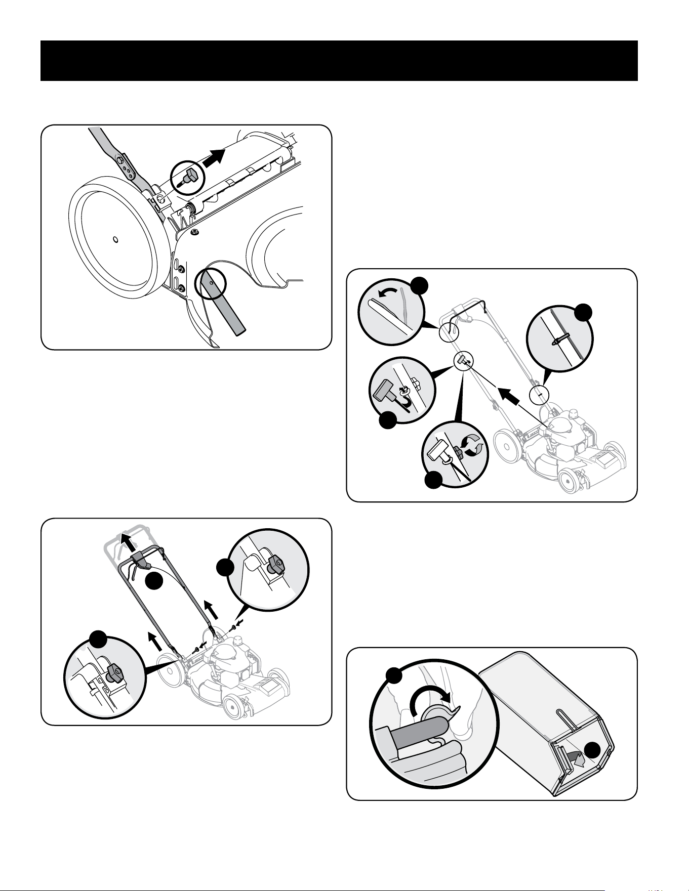
28
MONTAJE
5. Retire la T-pernos de la manija entre corchetes como se muestra en la Figura
3.
Figura 6
6. Siga los siguientes pasos para completar conjunto del mango:
a. Tire hacia arriba en el asa hasta agujeros en la manija (que se
muestra en la Figura 3 corte de la cubierta) se alinean con los
agujeros en el mango soporte. Vea la Figura 4.
NOTA: Al tirar hacia arriba la palanca, asegúrese de que no tire de manejar
todo el camino.
b. Inserte el T-pernos quitó anteriormente a través del mango
corchetes y asa inferior y apriete bien para asegurar el mango en su
lugar. Vea la Figura 4.
a
b
b
Figura 7
7. La guía de la cuerda, que está conectada a la varilla de sostén, se encuentra
sobre el lado derecho de la manija inferior. Vea la Figura 6.
a. Sostenga la manija de control de la cuchilla contra la manija superior.
b. Jale la cuerda de arranque para sacarla del motor. Suelte el control
de la cuchilla.
c. Deslice la cuerda de arranque en la guía.
d. Utilice abrazaderas de cable proporcionados para asegurar el control
de la cuchilla y cables de la unidad a la manija inferior como se
muestra en la Figura 6.
IMPORTANTE: Para reducir el desgaste y permitir un funcionamiento
correcto, asegúrese de dejar un espacio en la parte superior del cable(s).
d
a
b
c
Figura 8
Conexión de la colectora de césped
1. Para ensamblar el colector de césped (de ser necesario), Haga el cierto
bolso es dio vuelta a la derecha el lado antes de reunir (la advertencia de la
etiqueta será por fuera):
a. Coloque la bolsa sobre el marco con el lado negro de plástico en el
fondo.
b. Deslice el canal de plástico sobre los ganchos del marco. Vea la Figura 7.
a
b
Figura 9
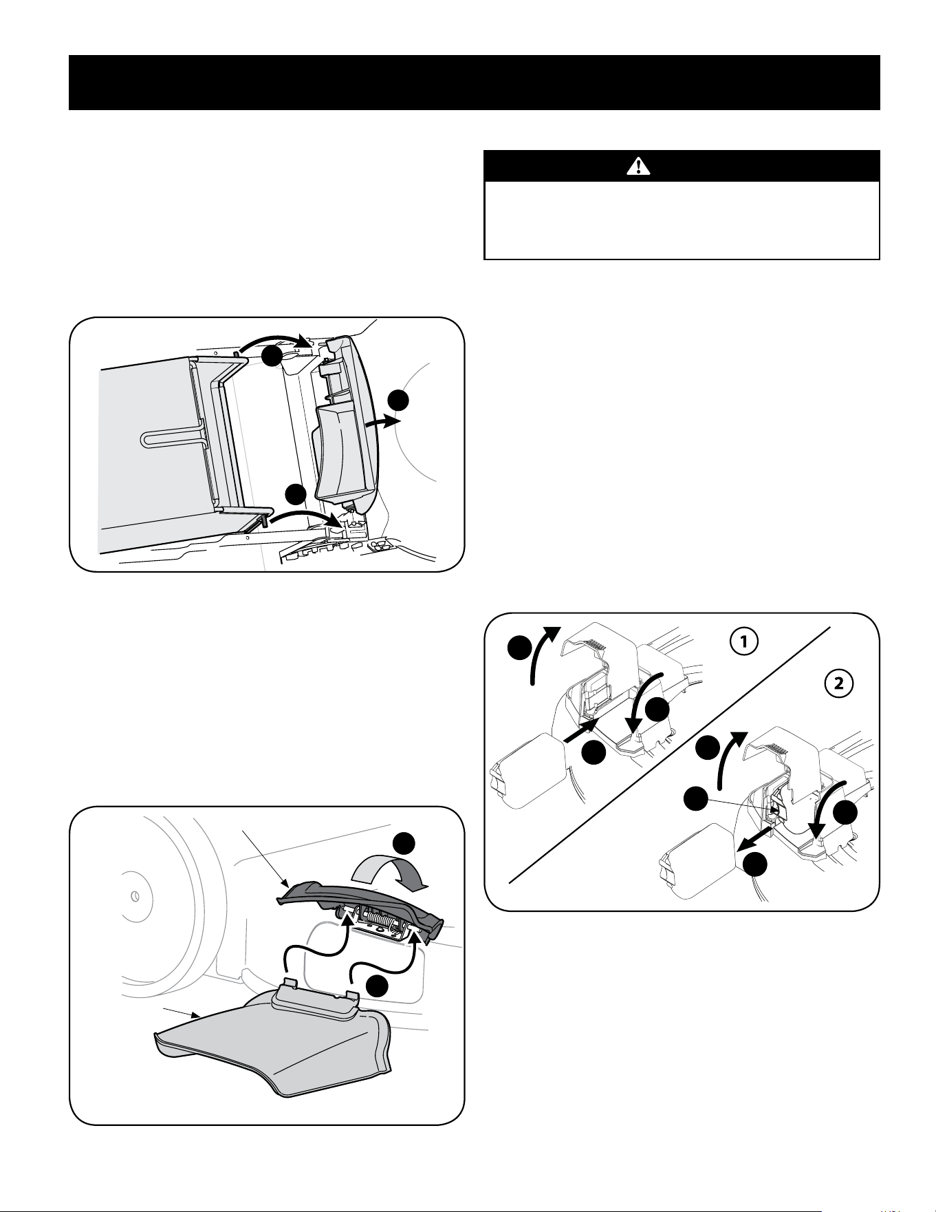
29
MONTAJE
2. Para acoplar el colector de césped:
a. Levante la puerta de descarga posterior.
b. Lugar de colección de césped en las ranuras en el mango entre
corchetes como se muestra en la Figura 8. Suelte la puerta de
descarga de modo que descanse sobre el colector de césped.
Para quitar al receptor de hierba, levante la puerta de descarga trasera en el
cortacésped. Ascensor césped y fuera de las ranuras en el mango entre paréntesis.
El reverso de liberación descarga la puerta para permitir que ello cerrara la apertura
trasera del cortacésped.
a
b
b
Figura 10
Conexión de Canal de Descarga Lateral
Su podadora ha sido enviada como abonadora. Si hace la conversión a descarga
lateral, asegúrese de que el colector de césped esté fuera de la unidad y que la
puerta de descarga trasera esté cerrada.
1. En el costado de la podadora, levante el adaptador para abono. Vea Figura 9.
2. Deslice los dos ganchos del canal de descarga lateral debajo del pasador de
bisagra sobre el montaje del adaptador para abono. Baje el adaptador para
abono. No extraiga la clavija para abono lateral en cualquier momento, aún
cuando no esté abonando.
1
2
Clavija para abono lateral
Canal de Descarga
Lateral
Figura 11
Instalar/Retirar el paquete de baterías (si está incluido)
ADVERTENCIA
Lea todas las advertencias de seguridad, instrucciones y leyendas de
precaución del paquete de baterías, del cargador y del producto. Si no se
siguen las advertencias y las instrucciones se pueden producir descargas
eléctricas, incendio y/o lesiones graves.
NOTA: Para asegurar el máximo rendimiento y duración de los paquetes de baterías
de ion-litio, cargue totalmente la batería antes del primer uso.
IMPORTANTE: Consulte el manual suministrado con el cargador de batería para la
recarga, y las instrucciones de mantenimiento y eliminación.
1. Para instalar el paquete de baterías realice lo siguiente. Vea la Figura 12.
a. Levante la tapa de la caja de baterías.
b. Inserte el paquete de baterías en la caja de baterías. Cuando la
batería quede correctamente conectada se escuchará un “clic”
sonoro.
c. Cierre la tapa de la caja de baterías.
2. Para retirar la batería realice lo siguiente. Vea la Figura 12.
a. Levante la tapa de la caja de baterías.
b. Presione el botón de desenganche del paquete de baterías.
c. Tire del paquete de baterías para retirarlo de la caja de baterías.
d. Cierre la tapa de la caja de baterías.
b
c
a
d
a
b
c
Figura 12
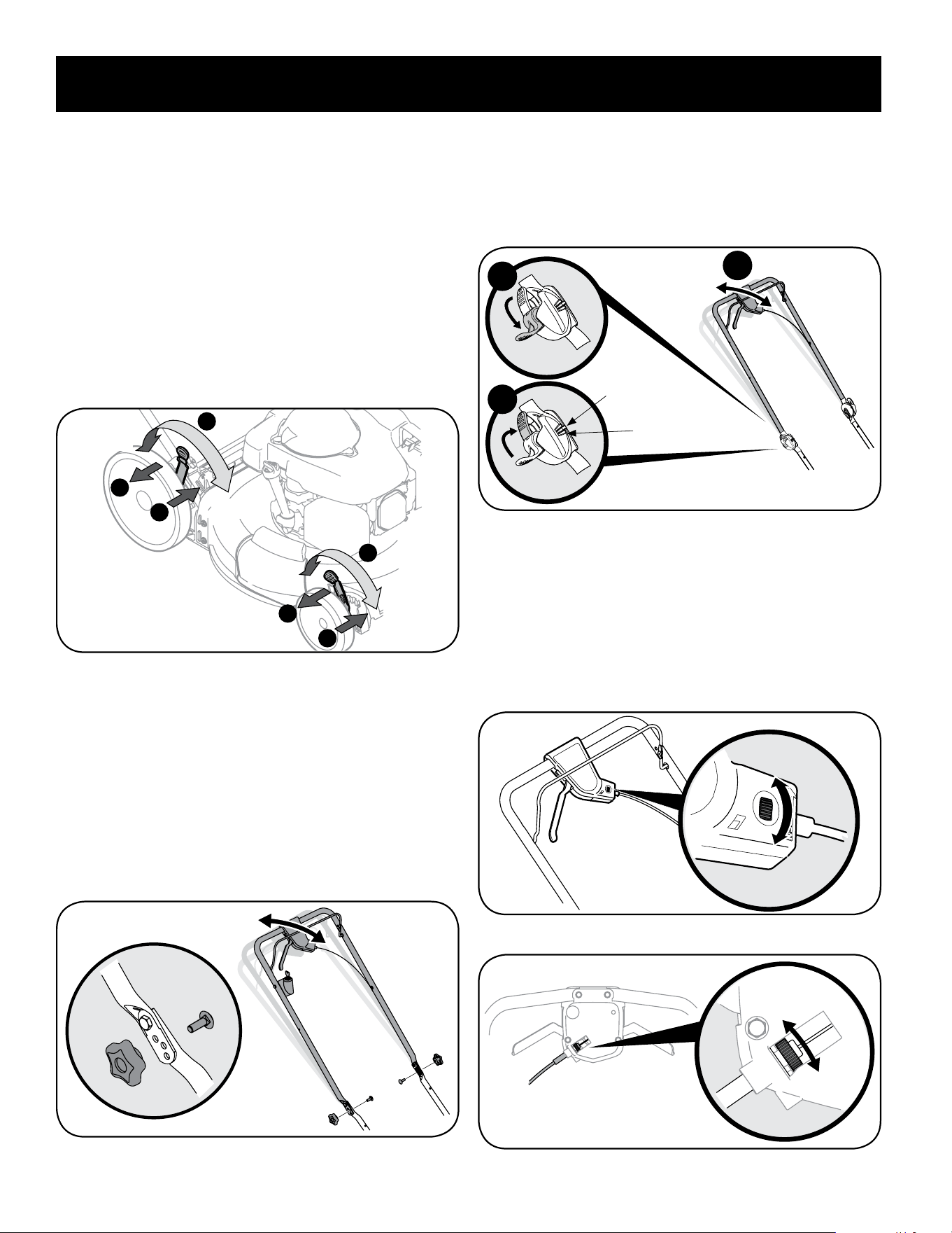
30
AJUSTES
Ajustes
Altura de corte
Hay una palanca de ajuste de altura de corte, situado encima de la rueda delantera
derecha y trasera.
1. Presione la palanca hacia la rueda (unidad tenderá a caer cuando se suelta la
palanca).
2. Muévala a cualquier de las posiciones para la altura de corte deseado. Vea la
Figura 10.
3. Libere la palanca hacia la cubierta de la podadora.
IMPORTANTE: Tanto las ruedas delanteras y traseras deben colocarse en la misma
posición relativa. Cuando el terreno es agreste o irregular cambie la palanca de
ajuste de la altura a una posición más alta. De esta manera se cuida más el césped.
3
2
2
1
3
1
Inferior
Inferior
Superior
Superior
Figura 13
Inclinación de la manija (si está incluido)
Por conveniencia de la operación, puede ajustar la inclinación de la manija de la
siguiente manera:
1. Handles with Knobs and Carage Bolts. See Figure 14 -
a. Quite los tornillos y tuercas de mariposa transporte de manejar. Vea la
Figura 11.
b. Coloque el mango en una de las tres posiciones que se sienta más
cómodo. Vea la Figura 11 inserción.
c. Fije la posición con tuercas y pernos de transporte eliminado antes.
Figura 14
2. Manijas EZ-Fold. Vea la Figura 15.
a. Coloque las palancas de desenganche en posición destrabada.
b. Mueva la manija superior para alinear el indicador de posición en la
posición más cómoda de las tres posiciones de la manija.
c. Coloque las manijas de desenganche en posición trabada.
a
c
b
Indicador de posición
Posiciones de la manija
Figura 15
Control de Transmisión
La rueda de ajuste está ubicada en el alojamiento de la manija de control de
transmisión y se utiliza para ajustar o aflojar la correa de transmisión. Deberá
ajustar el control de transmisión si la podadora no se autopropulsa con el control
de transmisión enganchado o si las ruedas de la podadora vacilan con el control de
transmisión enganchado. Si ocurre alguna de estas condiciones, rote la rueda de
ajuste en sentido de las agujas del reloj para ajustar el cable o en sentido contrario a
las agujas del reloj para aflojar el cable. Vea la Figura 12 o Figura 13.
Ajustar
Aflojar
Figura 16
Ajustar
Aflojar
Figura 17
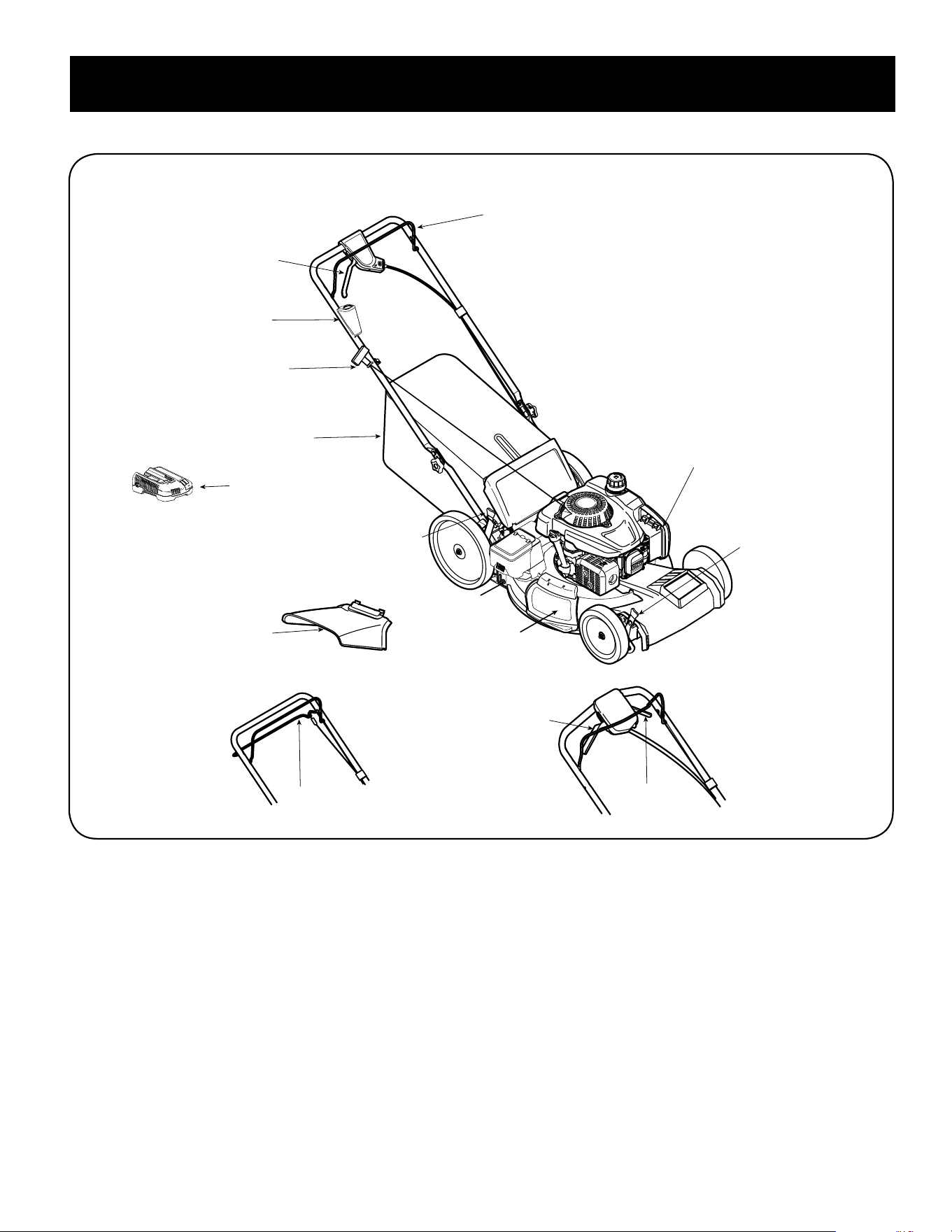
31
OPERACIÓN
Control de la
transmisión*
Control de la
transmisión*
Control de la
transmisión*
Figura 18
Arrancador
de retroceso
Control de
cuchilla
Palanca de
ajuste de altura
de corte
Palanca de
ajuste de altura
de corte
Canal de
Descarga Lateral
Lavado de la
Plataforma*
Control de la
transmisión*
Arranque Eléctrico
Pulsar Tecla*
Clavija para
abono
Compartimento
de la batería*
Colector de
Césped*
Cargador de
batería
* si está incluido

32
OPERACIÓN
Cumple con las normas de seguridad de ANSI
Las cortadoras de césped Craftsman cumplen con las normas de seguridad del Instituto Estadounidense de Normas Nacionales (ANSI).
Control de Cuchilla
El control de la cuchilla está unido a la manija superior. Presione la manija de control
de la cuchilla contra la manija superior para operar la unidad. Suelte la manija de
control de la cuchilla para detener el motor y la cuchilla.
ADVERTENCIA
El control de la cuchilla es un dispositivo de seguridad. Nunca intente
anular su funcionamiento.
Control de la Transmisión - fianza o una sola palancasi
está incluido)
El control de transmisión se encuentra ubicado por debajo de la manija superior
y se utiliza para enganchar la transmisión. Apriételo contra la manija superior
para enganchar la transmisión, libérelo para disminuir la velocidad o detener la
podadora.
Control de la Transmisión - palanca doble (si está
incluido)
Los controles de transmisión se encuentra ubicado por debajo de la manija superior
y s utiliza para enganchar la transmisión. Apriételo la derecha, izquierda o la
derecha y la izquierda los controles contra la manija superior para enganchar la
transmisión, libérelo para disminuir la velocidad o detener la podadora.
Llave-botón de arranque eléctrico (si está incluido)
La llave-botón de arranque eléctrico se encuentra sobre el lado derecho de la manija
superior. Es una llave-botón removible y se provee solo en los modelos de arranque
eléctrico.
Palanca de Ajuste de la Altura de Corte
Una palanca de ajuste se encuentra en la rueda trasera derecha y el otro se
encuentra en la rueda delantera derecha. Los dos palancas tienen que estar en la
misma posición relativa para asegurar un corte uniforme. Para ajustar la altura de
corte, se refieren a la sección de Montaje.
Canal de Descarga Lateral (si está incluido)
Su cortacésped es transportado como un mulcher. Para descargar los recortes
de periódico de hierba al lado en cambio, siga las instrucciones en la sección de
Montaje para atar el canal de descarga lateral.
ADVERTENCIA
Mantenga sus manos y pies alejados del área del canal de la plataforma de
corte. Consulte la etiqueta de advertencias en la unidad.
Lavado de la Plataforma (si está incluido)
La plataforma de su podadora está equipada con un puerto de agua sobre su
superficie como parte del sistema de lavado de la plataforma. Utilice el lavado de
la plataforma para lavar la parte inferior de la plataforma y quitar los recortes de
césped.
Clavija Para Abono (si está incluido)
El adaptador para abono se utiliza únicamente para propósitos de abono. En vez
de recolectar los recortes del césped en un colector de césped o canal de descarga
lateral, algunos modelos de podadora tienen la opción de recircular los recortes en
el césped. Esto se llama abonar.
Escudo de Ruta (si está incluido)
El escudo de ruta se adjunta a la parte trasera de la máquina y está ahí para
proteger al operador de escombros que vuelan. No utilice el cortacésped a menos
que el escudo es totalmente funcional y en su lugar.
Lavado de la Plataforma (si está incluido)
La plataforma de su podadora está equipada con un puerto de agua sobre su
superficie como parte del sistema de lavado de la plataforma. Utilice el lavado de
la plataforma para lavar la parte inferior de la plataforma y quitar los recortes de
césped.
Arrancador de Retroceso
El arrancador de retroceso está unido a la manija superior derecha. Para encender la
unidad colóquese detrás de la misma y tire de la cuerda del arrancador de retroceso.
Tapón de aceite/varilla de medición del nivel de aceite
Consulte el manual del operador del motor embalado con su segadora para el
llenado de aceite detallada, revisar y cambiar las instrucciones.
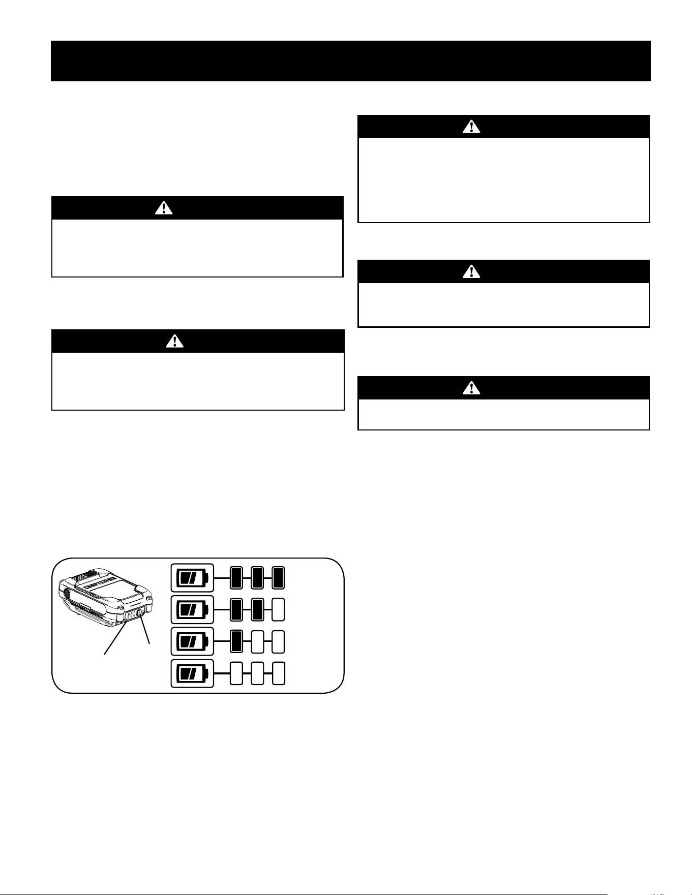
33
OPERACIÓN
Llenado de gasolina y aceite
Consulte en el Manual del operador del motor información adicional sobre el motor.
1. Agregue el aceite provisto antes de arrancar la cortadora de césped la
primera vez.
2. Realice el mantenimiento del motor con gasolina como se indica en el
Manual del operador del motor.
ADVERTENCIA:
La gasolina es altamente inflamable y explosiva y usted puede quemarse
o lesionarse gravemente al reabastecer. Pare el motor y mantenga lejos
el calor, las chispas y las llamas. Reabastezca sólo al aire libre. Limpie
inmediatamente los derrames.
Control de la carga del paquete de baterías (si está
incluido)
WARNING
Lea todas las advertencias de seguridad, instrucciones y leyendas de
precaución del paquete de baterías, del cargador y del producto. Si no se
siguen las advertencias y las instrucciones se pueden producir descargas
eléctricas, incendio y/o lesiones graves.
IMPORTANTE: Consulte el manual suministrado con el cargador de batería para la
recarga, y las instrucciones de mantenimiento y eliminación.
1. Presione el botón del indicador de batería en la parte delantera del paquete
de baterías para controlar el nivel de carga. Vea la Figura 19.
• Batería cargada: Una de las tres luces del indicador de batería se ilumina
para mostrar el nivel de carga.
• Batería descargada: Si no se muestra ninguna luz, cargue el paquete de
baterías. Consulte el manual suministrado con el cargador de batería para
ver las instrucciones de carga.
Carga completa
Sin carga
Indicador de
batería
Botón del
indicador
de batería
Figura 19
Para Encender el Motor
ADVERTENCIA
Asegúrese de que ninguna persona aparte del operador permanezca
cerca de la cortadora mientras arranca el motor u opera la misma. Nunca
encienda el motor en espacios cerrados o en una zona con poca ventilación.
El escape del motor contiene monóxido de carbono, un gas inodoro y letal.
Mantenga las manos, los pies, el cabello y la ropa suelta alejados de las
partes móviles del motor y de la cortadora.
Consulte el Manual del Operador del motor para obtener instrucciones sobre cómo
arrancar y parar el motor.
ADVERTENCIA
De retracción rápida del cordón de arranque (soborno) tirará de mano y el
brazo hacia el motor más rápido de lo que puede dejar ir. Las fracturas de
huesos, fracturas, contusiones o esguinces podría resultar.
Para Detener El Motor
1. Suelte la manija de control de la cuchilla para detener el motor y la cuchilla.
ADVERTENCIA
Espere a que la cuchilla se haya detenido por completo antes de hacer
cualquier trabajo en la cortadora o de retirar el colector de césped.
Uso de la cortadora de césped
Asegúrese de que el césped está libre de piedras, palos, cables u otros objetos
que pudiesen dañar la cortadora o el motor. Dichos objetos pueden ser arrojados
accidentalmente por la cortadora en cualquier dirección y provocar lesiones
personales graves al operador y a otras personas.
1. Realice uno de los siguientes:
• Control de la Transmisión - fianza o una sola palanca - Una vez que el motor
esté funcionando, apriete el control de transmisión contra la manija superior
para propulsar la podadora.
• Control de la Transmisión - palanca doble -
a. Una vez que el motor esté funcionando y sin dejar de mantener el
control de la cuchilla, apriete uno (o ambos en coche) los controles de
la transmisión contra la manija superior para propulsar la podadora.
Vea Figura 17.
b. Para cambiar la velocidad, libere el control de velocidad de
movimiento a la velocidad deseada.
NOTE: Seleccionando una velocidad de paseo, use la primera velocidad hasta
que usted sea cómodo y familiar con la operación del cortacésped.
IMPORTANTE: Si están cambiando las velocidades, mientras que la
cortadora está parado, puede ser difícil de cambiar en la primera velocidad
en determinadas condiciones. Esto es fácil de remediar con una breve
participación de la palanca de accionamiento.
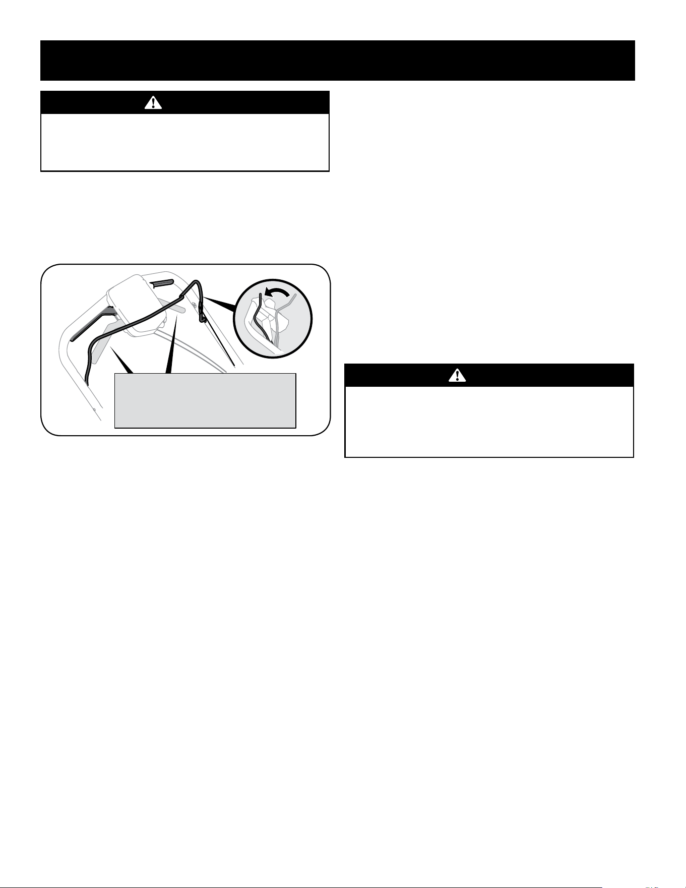
34
OPERACIÓN
ADVERTENCIA
Al operar una cortadora de césped es posible que objetos extraños sean
arrojados a los ojos, lo cual puede dañarlos gravemente. Utilice siempre
gafas de seguridad durante la operación de la cortadora de césped o
mientras la ajusta o repara.
NOTA: La máquina está equipada con un avanzado sistema de tracción interior de
la facilidad de uso y cambios suaves. Al girar o tirar de la unidad hacia atrás, usted
puede notar más alta que la resistencia normal en las ruedas traseras bajo ciertas
condiciones. Esto es perfectamente normal y se puede remediar, al permitir la
unidad para rodar un poco hacia adelante sin la palanca de accionamiento (s) ha
ejercido antes de tirar hacia atrás.lever(s) engaged before pulling backwards.
Involucrar a la derecha, la izquierda
o la derecha y la izquierda el control
de las palancas para impulsar la
podadora.
Figura 20
Uso como Abonadora
Para abonar el césped, quite el colector de césped y el canal de descarga lateral de
la máquina. La puerta de descarga posterior deberá estar cerrada. Para un abono
eficiente, no corte césped húmedo. Si el césped ha crecido más de 10,2 cm. (4
pulg.) no se recomienda el uso de la podadora como abonadora. En ese caso, use el
colector de césped para embolsar los recortes.
Uso del Colector de Césped
Puede utilizar el colector de césped para recoger dichos recortes mientras opera la
podadora.
1. Acople el colector de césped siguiendo las instrucciones en la sección de
Montaje. Los recortes de césped se recolectarán automáticamente en la
bolsa a medida que pase la podadora. Opere la podadora hasta que la bolsa
de recolección esté llena.
2. Detenga el motor por completo soltando la manija de control de la cuchilla.
Compruebe que la unidad se haya detenido por completo.
3. Para deshacerse de los recortes de césped levante la puerta de descarga y
tire de la bolsa de recolección hacia arriba, apartándola de la podadora.
ADVERTENCIA
Si golpea un objeto extraño, detenga el motor. Retire el cable de la bujía,
inspeccione detenidamente la cortadora para ver que no tenga daños, y
repare el daño antes de volver a encender y operar. El exceso de vibración
de la cortadora durante la operación es una indicación de daño. Se debe
inspeccionar y reparar la unidad lo antes posible.
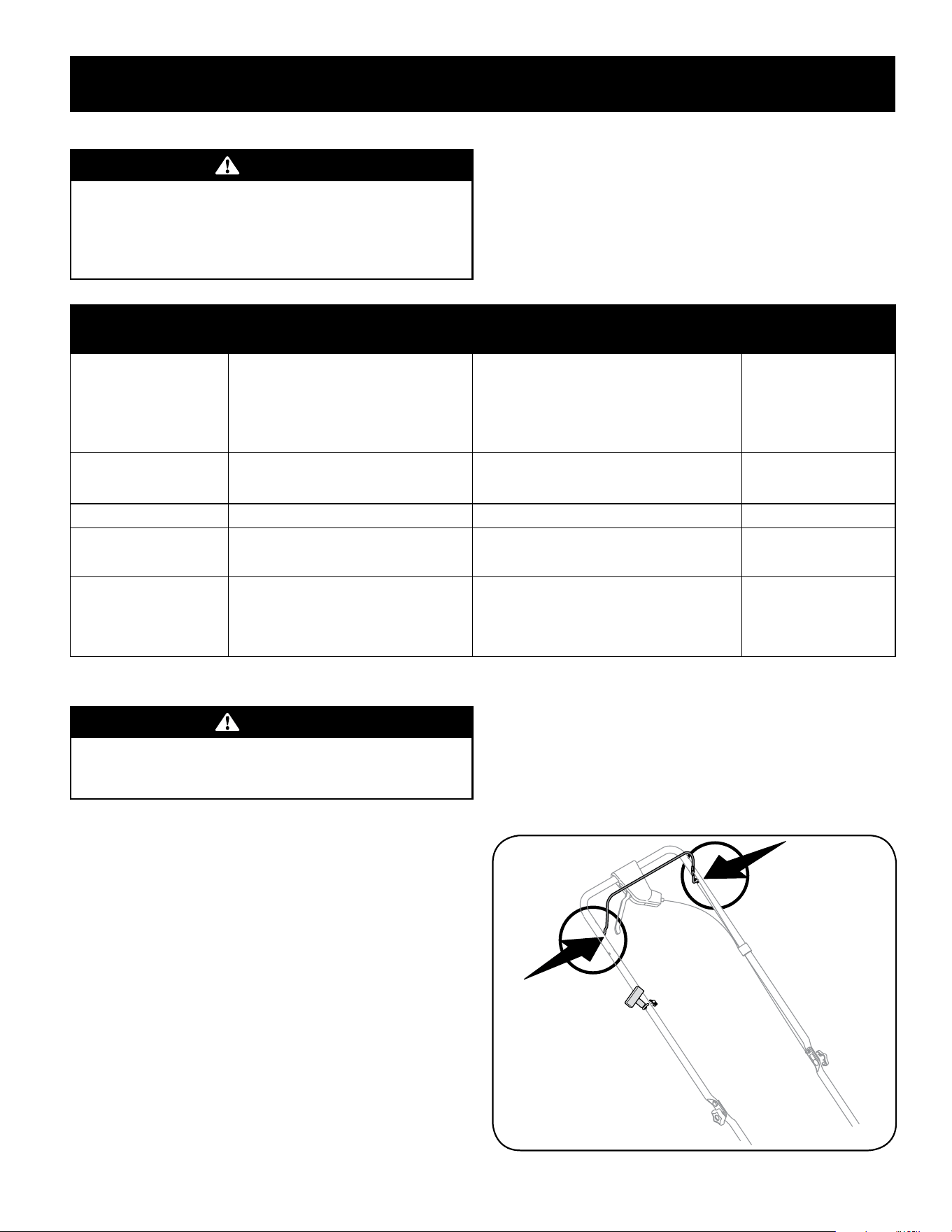
35
SERVICIO Y MANTENIMIENTO
ADVERTENCIA
Antes de realizar cualquier tipo de mantenimiento o servicio, desenganche
todos los controles y detenga el motor. Espere a que se detengan
completamente todas las piezas móviles. Desconecte el cable de la bujía
y póngalo haciendo masa contra el motor para evitar que se encienda
accidentalmente.
Siga el cronograma de mantenimiento que se presenta a continuación. Esta tabla
sólo describe pautas de servicio. Utilice la columna Registro de Servicio para hacer el
seguimiento de las tareas de mantenimiento completadas. Para ubicar el Centro de
Servicio más cercano o para programar un servicio, simplemente comuníquese con
al teléfono 1-888-331-4569.
Consulte el manual del operador del motor embalado con la podadora para
obtener instrucciones detalladas sobre cómo llevar a cabo muchos de los siguientes
elementos de mantenimiento.
PROGRAMA DE MANTENIMIENTO
Intervalo Artículo Servicio Registro
de servicio
Cada uso 1. Nivel de aceite del motor
2. Piezas sueltas o faltantes
3. Depurador de aire
4. Unidad y motor
1. Verificar
2. Ajustar o reemplazar
3. Verificar
4. Limpie
Anualmente o 25 horas 1. Depurador de aire/ Pre-Cleaner *
2. Varillajes/pivotes de control y ruedas
1. Limpiar o reemplazar
2. Lubricar con aceite ligero
Anualmente o 50 horas 1. Silenciador 5. Verificar
Anualmente 1. Bujía de encendido
2. Depurador de aire/ Pre-Cleaner
1. Reemplazar
2. Reemplazar
Antes de almacenar 1. Sistema de combustible 1. Hacer funcionar el motor hasta que se detenga
por falta de combustible o añadir estabilizador
de un tanque lleno de combustible nuevo
antes de su almacenamiento.
* Limpio más a menudo en condiciones polvorientas o cuando los escombros aerotransportados están presentes.
ADVERTENCIA
Detenga siempre el motor, deje que el motor se enfríe, desconecte el cable
de la bujía y haga masa contra el motor antes de realizar cualquier tarea de
mantenimiento a su máquina.
Recomendaciones Generales
• Respete siempre las reglas de seguridad cuando realice tareas de
mantenimiento.
• La garantía de esta cortadora no cubre elementos que han estado sujetos
al mal uso o la negligencia del operador. Para recibir el reembolso total de
la garantía, el operador deberá dar mantenimiento al equipo tal y como se
indica en este manual.
• El cambio de la velocidad controlada del motor invalidará la garantía del
motor.
• Todos los ajustes deben ser verificados por lo menos una vez en cada
estación.
• Revise periódicamente todos los sujetadores y compruebe que estén bien
ajustados.
Lubricación
Control de la cuchilla
Lubrique con aceite ligero los puntos de pivote del control de la cuchilla y la
transmisión al menos una vez cada estación. Estos controles debe funcionar
libremente en ambas direcciones. Vea la Figura 21.
Figura 21
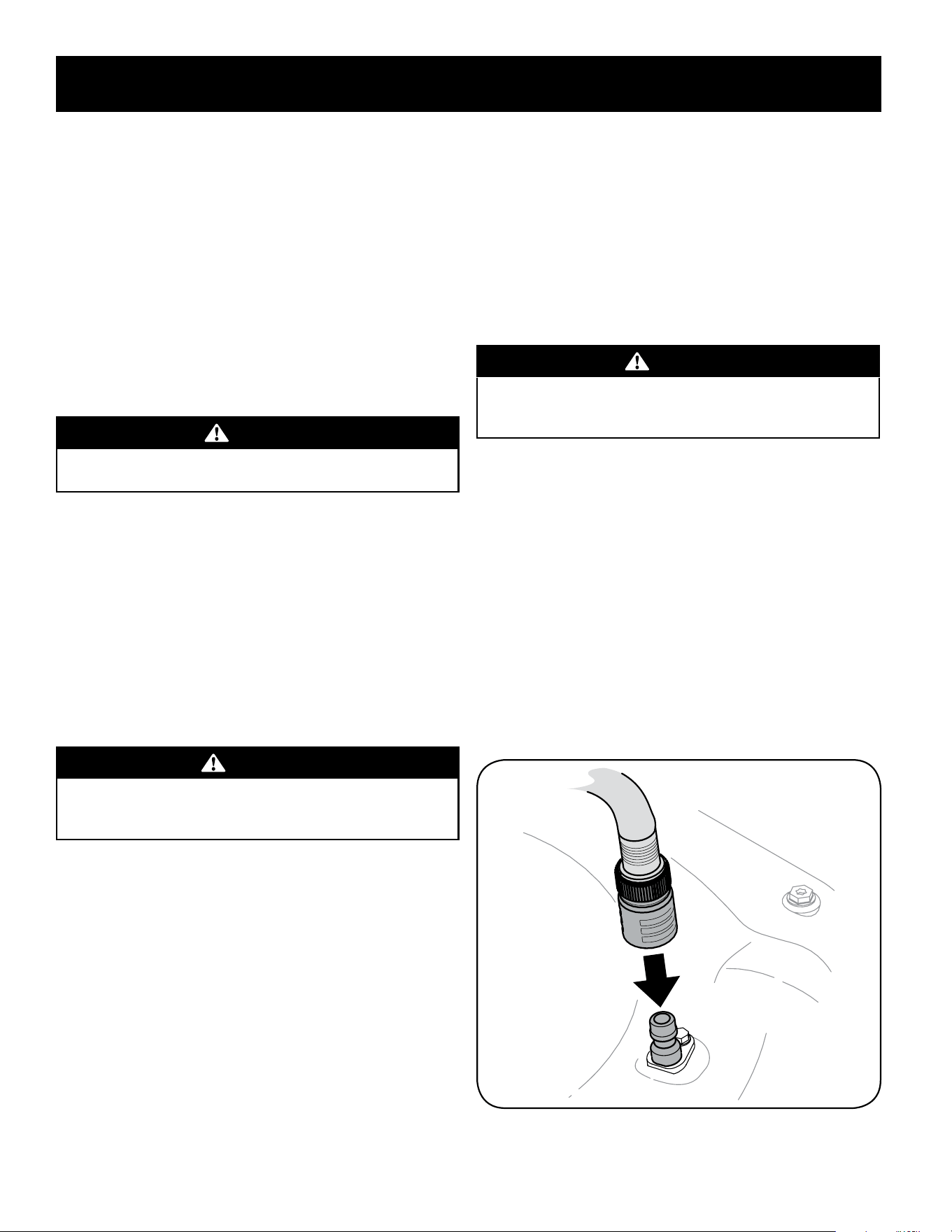
36
SERVICIO Y MANTENIMIENTO
Mantenimiento Del Motor
Consulte el manual del motor entregado con su bordeadora para obtener una
descripción detallada de todas las especificaciones de servicio relacionadas con el
motor.
Limpie el motor
• Diariamente o antes de cada uso, limpie el césped, la grasa o los residuos
acumulados del motor. Mantenga limpios el varillaje, los resortes y los
controles. Mantenga el área que rodea al silenciador y detrás del mismo libre
de cualquier residuo combustible.
• El mantenimiento del motor en condiciones limpias permite el movimiento
de aire alrededor del mismo.
• Las partes del motor se deben mantener limpias para reducir el riesgo de
sobrecalentamiento y combustión de los residuos acumulados.
PRECAUCIÓN
No use agua para limpiar las piezas del motor. El agua puede contaminar el
sistema de combustible. Use un cepillo o un trapo seco.
Mantenimiento de la cortadora
Cuidado de la plataforma
Debe limpiar la parte inferior de la plataforma de la cortadora después de cada uso
para prevenir la acumulación de recortes de césped u otros desechos. Consulte los
siguiente pasos para una limpieza adecuada.
1. Deje el motor en marcha hasta que se acabe el combustible. No intente
verter combustible del motor. Desconecte el cable de la bujía. Consulte el
Manual del operador del motor.
2. Incline la cortadora de manera que quede apoyada sobre la caja. Mantenga
hacia arriba el lateral donde se encuentra el filtro de aire. Sostenga
firmemente la cortadora.
ADVERTENCIA
Nunca incline la cortadora más de 90 grados en ninguna dirección y no deje
la cortadora inclinada. Se puede filtrar aceite dentro de la parte superior
del motor y causar problemas de arranque.
3. Raspe y limpie la parte inferior de la plataforma mediante el uso de una
herramienta adecuada.
NOTA: Quitando estos artículos, la arandela también pueden liberarse de el
cigüeñal. Esté seguro para hacer la nota de la orientación de este artículo
para nueva sesión.
4. Vuelva a colocar la cortadora sobre
sus ruedas en el suelo.
Lavado de la Plataforma (si está incluido)
La plataforma de su podadora está equipada con un puerto de agua sobre su
superficie como parte del sistema de lavado de la plataforma.
Utilice el lavado de la plataforma para lavar la parte inferior de la plataforma y
quitar los recortes de césped e impedir la acumulación de sustancias químicas
corrosivas.
Realice los siguientes pasos DESPUÉS DE CADA CORTE DE CÉSPED:
1. Empuje la podadora a una zona nivelada y despejada del césped, que se
encuentre suficientemente cerca de una canilla de agua al alcance de la
manguera del jardín. Si adjunta, quite la bolsa de césped.
PRECAUCIÓN
Asegúrese de que el canal de descarga de la podadora NO ESTÉ ORIENTADO
en la dirección en que se encuentran la casa, el garaje, los vehículos
estacionados, etc.
2. Enrosque el acople de manguera (embalado con el Manual del Operador de
su tractor) en el extremo de la manguera de jardín.
3. Una el acople de la manguera al puerto de agua que se encuentra en la
superficie de la plataforma. Vea la Figura 22.
4. Abra el suministro de agua.
5. Arranque el motor como se describe en la sección de Operación.
6. Hacer funcionar el motor durante dos minutos como mínimo, permitiendo
que la parte inferior de la plataforma de corte se lave a fondo.
7. Hoja de control de la cuchilla al parar el motor y la cuchilla.
8. Desconecte el agua y retire el acoplador de la manguera desde el puerto de
agua que se encuentra en la superficie de la plataforma.
Después de limpiar la plataforma, reinicie la podadora. Mantenga el motor y la
cuchilla en funcionamiento durante dos minutos por lo menos para permitir que se
seque totalmente el lado inferior de la misma.
Figura 22
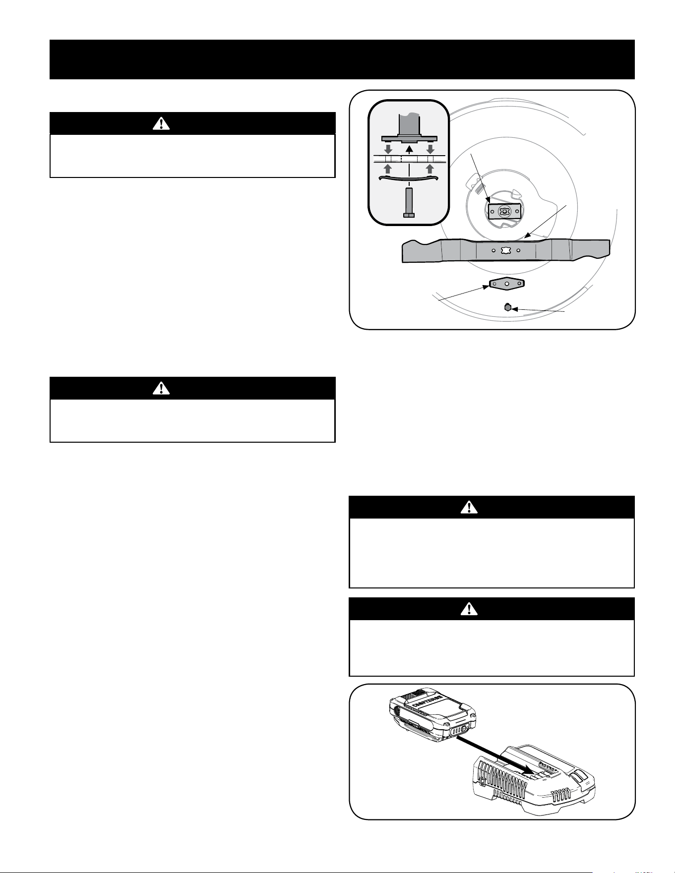
37
SERVICIO Y MANTENIMIENTO
Cuidado de la cuchilla
ADVERTENCIA
Cuando saque la cuchilla de corte para afilarla o reemplazarla, protéjase las
manos usando un par de guantes para trabajo rudo o un trapo grueso para
sostener la cuchilla.
Inspeccione periódicamente el adaptador de la cuchilla en busca de rajaduras,
especialmente cuando golpee un objeto extraño. Realice los reemplazos
que resulten necesarios. Siga los pasos que aparecen debajo para realizar el
mantenimiento de la cuchilla.
1. Desconecte el capuchón del cable de la bujía. Gire la cortadora de césped
sobre el costado y compruebe que el filtro de aire y el carburador queden
mirando hacia arriba.
2. Saque el perno y el soporte de campana de la cuchilla que sostienen la
cuchilla y el adaptador de la misma al cigüeñal del motor. Vea la Figura 23.
3. Saque la cuchilla y el adaptador del cigüeñal.
NOTA: Quitando estos artículos, la arandela también pueden liberarse de el
cigüeñal. Esté seguro para hacer la nota de la orientación de este artículo
para nueva sesión.
ADVERTENCIA
Si la cuchilla está desequilibrada generará vibraciones excesivas cuando
rote a altas velocidades. Puede producir daños a la cortadora de césped y se
puede romper, causando así lesiones personales.
4. Saque la cuchilla del adaptador para comprobar el equilibrio. Balancee la
cuchilla sobre un destornillador de eje redondo para inspeccionarla. Saque
metal del lado pesado hasta que quede bien equilibrada. Cuando afile la
cuchilla, siga el ángulo original de la muela como guía. Afile cada borde de
corte por igual para mantener el balance de la cuchilla.
5. Lubrique el cigüeñal del motor y la superficie interna del adaptador de
la cuchilla con aceite ligero. Deslice el adaptador de la cuchilla sobre el
cigüeñal del motor. Instale la cuchilla en el adaptador con el lado marcado
“Grass Side” (o con el número de parte) hacia el piso cuando la cortadora de
césped está en posición de funcionamiento. Asegúrese que la cuchilla quede
alineada y asentada en las bridas del adaptador. Vea la Figura 23 inserto.
6. Coloque el soporte de campana de la cuchilla en la misma. Alinee las
muescas del soporte de campana de la cuchilla con los orificios pequeños de
la cuchilla.
7. Vuelva a colocar el perno hexagonal y ajústelo según los siguientes valores
de torsión: 450 lb-pulg como mínimo, 600 lb-pulg como máximo.
Para garantizar la operación segura de la cortadora de césped, revise
periódicamente el perno de la cuchilla para determinar si está bien ajustado.
Cuchilla
Adaptador de la
Misma
Perno
Soporte de
Campana de la
Cuchilla
Figura 23
Cuidado de la correa
NOTA: Para cambiar la correa de paseo de la cortadora de césped es necesario extraer
varios componentes. Solicite a un centro autorizado de servicio que realice el reemplazo
de la correa.
Carga de la batería del arrancador eléctrico (si está
equipado)
IMPORTANTE: Consulte el manual suministrado con el cargador de batería para la
recarga, y las instrucciones de mantenimiento y eliminación.
WARNING
La batería contiene fluido corrosivo y material tóxico; manipule con
cuidado y mantenga alejado de los niños. No perfore, desensamble, mutile
o prenda fuego a la batería. Los gases explosivos podrían purgarse durante
la carga o descarga. Utilice en un área bien ventilada, alejada de las fuentes
de ignición.
WARNING
Lea todas las advertencias de seguridad, instrucciones y leyendas de
precaución del paquete de baterías, del cargador y del producto. Si no se
siguen las advertencias y las instrucciones se pueden producir descargas
eléctricas, incendio y/o lesiones graves.
Figura 24

36
ALMACENAMIENTO FUERA DE TEMPORADA
ADVERTENCIA
Nunca almacene la cortadora de césped con combustible en el tanque en
un espacio cerrado o en áreas con poca ventilación, donde los gases del
combustible puedan alcanzar el fuego, chispas o una luz piloto como la que
tienen algunos hornos, calentadores de agua, secadores de ropa o algún
otro dispositivo a gas.
Preparación del Motor
Ya que los motores almacenaron más de 30 días:
• Para impedir a la goma formarse en el sistema de combustible o en partes
de carburador, dirijas el motor hasta que esto se pare a falta del combustible
o añadir un aditivo de gasolina al gas en el tanque. Si usted usa un aditivo
de gas, dirige el motor durante varios minutos para poner en circulación el
aditivo por el carburador.
• No se requiere un cambio de aceite, pero si el deseo de cambiar el aceite a
continuación, cambiar mientras el motor está caliente.
• Limpie el motor de escombros superficiales.
Preparación de la Cortadora de Césped
• Limpie y lubrique la cortadora como se describe en las instrucciones de
lubricación.
• No utilice una lavadora a presión ni una manguera de jardín para limpiar su
unidad.
• Cubra la cuchilla de la cortadora con grasa para chasis para impedir la
oxidación.
ADVERTENCIA
Al manipular la cuchilla de corte, protéjase las manos usando un par de
guantes gruesos o un trapo grueso para sostener la cuchilla.
• Refiérase a la Preparación del Motor para instrucciones de almacenaje de
motor correctas.
• Almacene la unidad en una zona limpia y seca. No la almacene cerca de
materiales corrosivos como por ejemplo fertilizantes.
Cuando almacene cualquier tipo de equipo motorizado en un galpón de depósito
metálico o con poca ventilación, tenga especial cuidado de realizarle un tratamiento
antioxidante al equipo. Use aceite ligero o silicona para recubrir el equipo,
especialmente los cables y partes móviles de su cortadora antes de almacenarla.
Batería
• La batería debe guardarse con una carga completa. El almacenamiento
prolongado de una batería descargada reducirá la vida útil y la capacidad de
la batería. Para la vida óptima de la batería, cargue la batería una vez al mes
durante el almacenamiento.
• Quitar Arranque eléctrico Empuje la llave y mantener en un lugar seguro
fuera del alcance de los niños.

39
SOLUCIÓN DE PROBLEMAS
ADVERTENCIA
Antes de realizar cualquier tipo del mantenimiento/servicio, suelte
todos los mandos y pare el motor. Espere hasta que todas las partes de
movimiento hayan venido a una parada completa. Desconecte el alambre
de bujía y báselo contra el motor para prevenir el comienzo involuntario.
Siempre lleve puestos cristales inastillables durante la operación o
realizando cualquier ajuste o reparaciones.
Esta sección se ocupa de cuestiones de menor importancia del servicio. Para localizar el más cercano Centro de Servicio, o para programar un servicio,
simplemente póngase en contacto con al 1-888-331-4569.
Problema Causa Solución
El motor no arranca
1. Control de la cuchilla desenganchado.
2. Se ha desconectado el capuchón de la bujía.
3. El depósito de combustible está vacío o el combustible
se ha echado a perder.
4. El motor no está cebado. (Si lo tiene)
5. La bujía no funciona correctamente.
6. El motor se desbordó.
7. Línea de combustible bloqueada.
1. Engrane el control de la cuchilla.
2. Conecte el cable al capuchón de la bujía.
3. Llene el tanque con gasolina limpia y nueva.
4. Cebe el motor tal como se explica en la sección de
Funcionamiento.
5. Limpie, ajuste la separación, o cambie la bujía.
6. Esperar unos minutos para reactivarse, pero no cebe.
7. Contacte con su centro de partes y reparaciones.
El motor no arranca con arranque
eléctrico
(Sólo arranque eléctrico unidades)
1. Arranque eléctrico clave Push no insertada
completamente.
2. Batería no está cargada.
3. Disparó el cortacircuitos.
1. Clave en la caja de arranque Inserte hasta que encaje en su lugar.
2. Cargue la batería.
3. Escombros puede estar bloqueando el funcionamiento de
la cuchilla. Pare el motor, retire Arranque eléctrico Key, y
desconecte casquillo de la bujía. Verifique hierba u otros
residuos no obstruya la hoja. Limpiar cuidadosamente los
desechos, si es necesario. Vuelva a colocar casquillo de la bujía y
vuelva a insertar clave.
Espere un minuto después de la desconexión de interruptor de
forma automática auto-reset después volver a intentar iniciar.
El motor funciona de manera
errática
1. El capuchón de la bujía está flojo.
2. El combustible se ha echado a perder.
3. La ventilación de la tapa del combustible está
obstruida.
4. Agua o suciedad en el sistema del combustible.
5. El filtro de aire está sucio.
6. Línea de combustible bloqueada.
1. Conecte y ajuste el capuchón de la bujía.
2. Llene el tanque con gasolina limpia y nueva.
3. Destape la ventilación.
4. Vacíe el tanque de combustible. Cargue combustible nuevo en
el depósito.
5. Consulte la sección Mantenimiento del manual de motor.
6. Contacte con su centro de partes y reparaciones.

40
SOLUCIÓN DE PROBLEMAS
Problema Causa Solución
El motor recalienta 1. El nivel de aceite del motor está bajo.
2. Flujo de aire restringido.
1. Llene el motor con la cantidad y tipo de aceite adecuado.
2. Limpie los residuos de alrededor de las aletas de refrigeración
del motor y del alojamiento del soplador.
El motor vacila a altas revoluciones 1. Poca separación de los electrodos de la bujía. 1. Ajuste la separación. Consulte la sección Mantenimiento del
manual de motor.
El motor funciona mal en marcha
lenta
1. Bujía atorada, averiada o exceso de separación.
2. El filtro de aire está sucio.
1. Limpie, reemplace o reajuste la separación.
2. Consulte la sección Mantenimiento del manual de motor.
Demasiada vibración 1. Cuchilla de corte floja o descentrada.
2. Cuchilla abollada.
1. Apriete la cuchilla y el adaptador Balancee la cuchilla.
2. Cambie la cuchilla.
La cortadora de césped no regresa
el recorte de césped como abono
1. Césped húmedo.
2. Césped demasiado alto.
3. La cuchilla de la cortadora no está afilada.
1. No corte el césped cuando esté mojado, espere hasta que sea
más tarde para hacerlo.
2. Corte una vez a altura de corte elevada, luego vuelva a cortar a la
altura deseada o haga un sendero de corte más angosto.
3. Afile o cambie la cuchilla.
Corte desigual 1. La posición de las ruedas no es correcta.
2. La cuchilla de la cortadora no está afilada.
1. Coloque las cuatro ruedas en la misma posición de altura.
2. Afile o cambie la cuchilla.
La podadora no
avanza por sí misma
1. Correa mal instalada.
2. Hay desechos bloqueando el funcionamiento de la
transmisión.
3. Correa dañada o desgastada.
4. Unidad de control de ajuste.
1. Compruebe la correa para ver si la polea está bien instalada y se
mueve correctamente.
2. Detenga el motor, desconecte el cable de la bujía y limpie los
desechos.
3. Inspeccione y, si es necesario, consulte sus piezas centro de
servico tener cinturón sustituido.
4. Ajuste la unidad de control. (Ver sección de Montaje y
Configuración).
CRAFTSMAN® is a registered trademark of Stanley Black & Decker, Inc., used under license.
CRAFTSMAN® es una marca registrada de Stanley Black & Decker, Inc., utilizada bajo licencia.
© 2018 CRAFTSMAN U.S. & Canada Only
CRAFTSMAN.com