INSTRUCTION MANUAL Lawn Tractor
ASSEMBLY & SET-UP
Contents of Carton
- Lawn Tractor (1)
- Steering Wheel (1) -- Cup Washer (1) & Hex Bolt (1)
- Operator’s Manual (1)
- Ignition Key (2)
- Seat (1)
- Engine Operator’s Manual (1)
- Plastic Oil Drain Sleeve (1) †
- Dash Shroud (1) †
- Fast Start Guide (1)†
- Oil Drain Hose (1) †
- Deck Wash Nozzle (1) †
- Parts/Warranty Document (1)
- Hood Scoop (1) †
- Hose Coupler (1) †
- Product Registration Card (1) †
† — If Equipped
NOTE: This Operator’s Manual covers several models. Features may vary by model. Not all features in this manual are applicable to all models and the model depicted may differ from yours. Refer to Figure 2-1 to match your transmission style; Foot Control CVT (Continuously Variable Transmission) or CVT (Continuously Variable Transmission). or Hydrostatic.
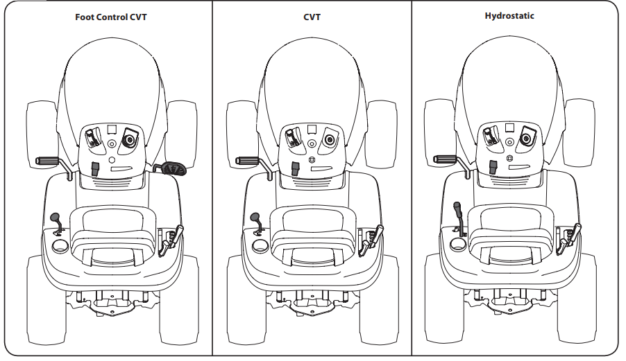
NOTE: This Operator’s Manual covers several models. Features may vary by model. Not all features in this manual are applicable to all models and the model depicted may differ from yours. Refer to Figure 1 to match your transmission style; Foot Control CVT (Continuously Variable Transmission) or CVT (Continuously Variable Transmission).
Tools Required
- Adjustable Wrench or Socket Set
Moving the Tractor Manually
Hydrostatic Models: Hydrostatic models are equipped with a hydrostatic relief valve when it is necessary to move the tractor manually. Activating this valve forces the fluid in the transmission to bypass its normal route, allowing the rear tires to “freewheel.” To engage the hydrostatic relief valve, proceed as follows:
1. Locate the hydrostatic bypass rod in the rear of the tractor
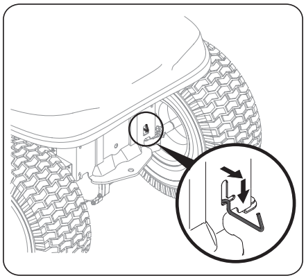
2. Pull the hydrostatic bypass rod outward, then down, to lock it in place
NOTE: The transmission will NOT engage when the hydrostatic bypass rod is pulled out. Return the rod to its normal position prior to operating the tractor.
IMPORTANT: Never attempt to move the tractor manually without first engaging the hydrostatic relief valve. Doing so will result in serious damage to the tractor’s transmission.
STOP! Continue to Controls & Operations section
Foot Control CVT & CVT Models: CVT models can be placed in the NEUTRAL (N)position when it is necessary to move the tractor manually. To move the tractor manually, place the shift lever in the NEUTRAL (N) position.
Connecting the Battery Cables
WARNING - CALIFORNIA PROPOSITION 65 WARNING: Battery posts, terminals, and related accessories contain lead and lead compounds, chemicals known to the State of California to cause cancer and reproductive harm. Wash hands after handling.
CAUTION: When attaching battery cables, always connect the POSITIVE (Red) wire to its terminal first, followed by the NEGATIVE (Black) wire
For shipping reasons, both battery cables on your equipment may have been left disconnected from the terminals at the factory. To connect the battery cables, proceed as follows:
NOTE: The positive battery terminal is marked Pos. (+). The negative battery terminal is marked Neg. (–)
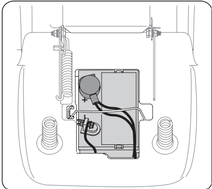
3. Remove the plastic cover, if present, from the positive battery terminal and attach the red cable to the positive battery terminal (+) with the bolt (a) and hex nut (b)
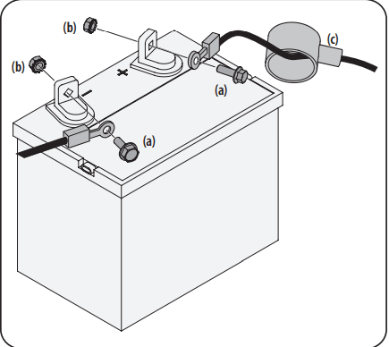
4. Remove the plastic cover, if present, from the negative battery terminal and attach the black cable to the negative battery terminal (–) with the bolt (a) and hex nut (b).
5. Position the red rubber boot (c) over the positive battery terminal to help protect it from corrosion.
NOTE: If the battery is put into service after the date shown on top/side of battery, charge the battery as instructed in the Service section your Operator’s Manual on page 24 prior to operating the tractor.
Shipping Brace Removal
- WARNING: Make sure the tractor’s engine is OFF, remove the ignition key, and set the parking brake before removing the shipping brace. Refer to the Controls & Operations section on page 16 for instructions on how to set the parking brake.
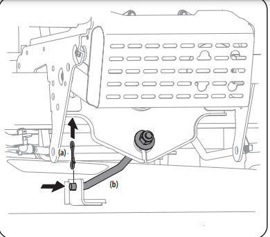
- Check the cutting deck for a shipping brace (a) that may be holding the chute deflector (b) upward for shipment. If the shipping brace (a) is present, it must be removed before operating the tractor. Holding the chute deflector (b) fully upward, remove the shipping brace (a). Lower the chute deflector (b) and discard the shipping brace (a).
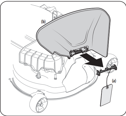
- WARNING: The shipping brace (a) is used for packaging purposes only, it must be removed and discarded before operating your tractor
- WARNING: The cutting deck is capable of throwing objects. Failure to operate the tractor without the chute deflector in the proper operating position could result in serious personal injury and/or property damage.
Attaching the Steering Wheel
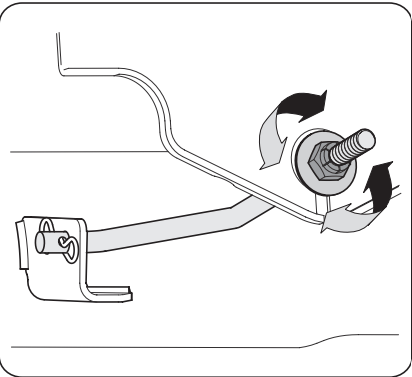
- If the steering wheel (a) for your tractor did not come attached, the hardware for attaching it has been packed within the steering wheel (a), beneath the steering wheel cap (b). Carefully pry OFF the steering wheel cap (b) and remove the cupped washer (c) and hex bolt (d)
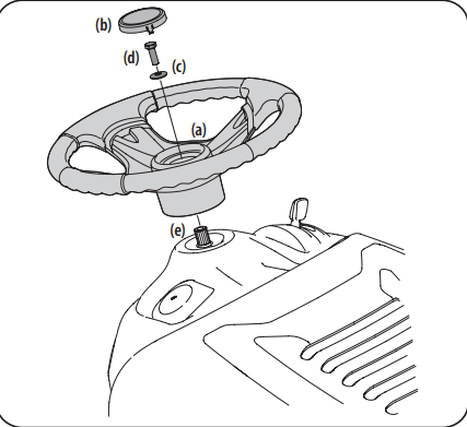
- With the wheels of the tractor pointing straight forward, place the steering wheel (a) over the steering shaft (e).
- Place the cupped washer (c) -- cupped side down -- over the steering wheel (a) and secure with the hex bolt (d).
- Place the steering wheel cap (b) over the center of the steering wheel (a) and push downward until it “clicks” into place.
Attaching the Seat
- If the seat for your tractor was not attached at the factory, refer to the following steps.
- NOTE: For shipping reasons, seats are either fastened to the tractor seat’s pivot bracket with a cable tie, or mounted backward to the pivot bracket. In either case, remove the seat from its shipping position.
1. Remove the seat adjustment knob (a) from the bottom of the seat (b
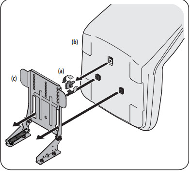
2. Align the seat (b) over the seat pivot bracket (c) as shown in Figure 6 and fit the seat (b) onto the seat pivot bracket (c) inserting the two tabs on the seat (b) bottom into the slots on the seat pivot bracket (c).
3. Slide the seat (b) rearward in the seat pivot bracket (c), lining up the center rear slot in the seat pivot bracket (c) with the remaining hole in the seat (b) base.
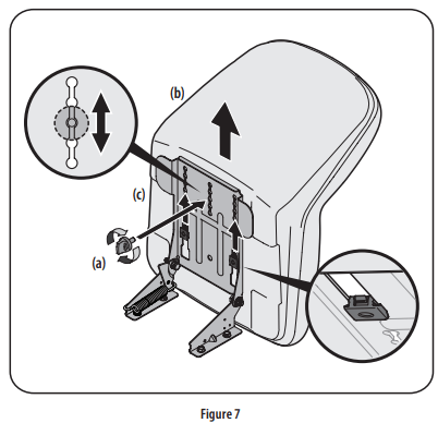
NOTE: Be certain the two seat tabs engage the seat pivot bracket as shown in the bottom right inset of Figure 7.
4. Select the desired position for the seat (b), and secure with the adjustment knob (a) removed in Step 1.
5. To adjust the position of the seat, remove the adjustment knob (a) on the bottom of the seat (b). Slide the seat (b) forward or backward as desired. Reinstall the adjustment knob (a).
Dash Shroud (If Equipped)
1. If the dash shroud (a) was shipped loose, the hardware for attaching the dash shroud (a) is shipped installed in the dash shroud (a). Remove the two bolts (b) from the dash shroud (a)
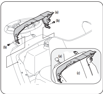
2. Mount the dash shroud (a) and align the mounting holes.
3. Secure the dash shroud (a) to the dash (c) with the bolts (b) removed in Step 1.
Tire Pressure
WARNING: Equal tire pressure should be maintained at all times. Never exceed the maximum inflation pressure shown on the sidewall of the tire.
The recommended operating tire pressure is:
- Approximately 10 psi for the rear tires
- Approximately 14 psi for the front tires
IMPORTANT: Refer to the tire sidewall for exact tire manufacturer’s recommended or maximum psi. Do not overinflate. Uneven tire pressure could cause the cutting deck to mow unevenly.
Gas & Oil Fill-up
- Oil
- IMPORTANT: Your tractor is shipped with motor oil in the engine. However, you MUST check the oil level before operating. Be careful not to overfill. Service and check the engine oil as instructed in the Engine Operator’s Manual. Read the instructions carefully.
- Gasoline: The gasoline tank is located under the hood. Do not overfill. WARNING: Use extreme care when handling gasoline. Gasoline is extremely flammable and the vapors are explosive. Never fuel machine indoors or while the engine is hot or running. Extinguish cigarettes, cigars, pipes, and other sources of ignition. NOTE : Purchase gasoline in small quantities. Do not use gasoline left over from the previous season, to minimize gum deposits in the fuel system.
- This engine is certified to operate on unleaded gasoline. For best results, fill the fuel tank with only clean, fresh, unleaded gasoline with a pump sticker octane rating of 87 or higher.
- Gasohol (up to 10% ethyl alcohol, 90% unleaded gasoline by volume) is an approved fuel. Other gasoline/alcohol blends, such as E85, are not approved.
- Methyl Tertiary Butyl Ether (MTBE) and unleaded gasoline blends (up to a maximum of 15% MTBE by volume) are approved fuels. Other gasoline/ether blends are not approved.
- Fill fuel tank outdoors or in well-ventilated area.
- Never remove gas cap or add fuel while the engine is hot or running. Allow engine to cool at least two minutes before refueling.
- If gasoline is spilled, wipe it off the engine and equipment. Move machine to another area. Wait five minutes before starting the engine.
To Add Gasoline: Refer to Figure 1 and proceed to your applicable model for your gas tank.
Hydrostatic Models
- Turn the engine OFF and let the engine cool at least two minutes before removing the fuel cap. The gasoline tank is located under the hood. Remove the fuel cap by turning it counter-clockwise.
- Fill the fuel tank with gasoline. Use only clean, fresh (no more than 30 days old), unleaded gasoline. Fill tank to the base of the filler neck to allow space for fuel expansion. DO NOT TOP OFF THE TANK WITH FUEL
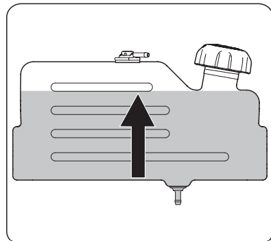
- Reinstall the fuel cap.
STOP! Continue to Setting the Deck Gauge Wheels (If Equipped)
Foot Control CVT Models & CVT Models
1. Turn the engine OFF and let engine cool at least two minutes before removing the fuel cap. The gasoline tank is located under the hood. Remove the fuel cap by turning it counter-clockwise.
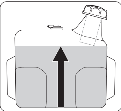
2. Fill the fuel tank with gasoline. Use only clean, fresh (no more than 30 days old), unleaded gasoline. Fill tank to no more than ½” below bottom of filler neck to allow space for fuel expansion.
3. Reinstall the fuel cap. IMPORTANT: Do not overfill the tank. Fill tank to no more than ½” below bottom of filler neck to allow space for fuel expansion. STOP! Continue to Setting the Deck Gauge Wheels (If Equipped)
Setting the Deck Gauge Wheels (If Equipped)
Move the tractor to a firm and level surface, preferably pavement, and proceed as follows:
- Select the height position of the cutting deck by placing the deck lift lever in the normally desired mowing height setting (there are six different cutting height notches on the right fender).
- Check the deck gauge wheels for contact or excessive clearance with the surface below. The deck gauge wheels should have between ¼” and ½” clearance above the ground.
- If the gauge wheels have excessive clearance or contact with the surface, adjust as follows:
- Raise the deck lift handle to its highest setting.
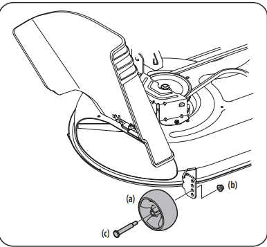
- Remove the front and rear deck gauge wheels (a) by removing the lock nuts (b) and shoulder screws (c) which secure them to the deck
- Place the deck lift lever in the desired mowing height setting.
- Reinsert the shoulder screws (c) into the index hole that leaves approximately ½” between the bottom of the deck gauge wheel (a) and the pavement. Secure in place with the lock nuts (c).
- Refer to Leveling the Deck in the Service section on page 26 of this manual for more detailed instructions regarding various deck adjustments.
Attaching the Hood Scoop (If Necessary/If Equipped)
1. On some tractors, a hood scoop may be included. If the hood scoop was not installed on the hood of your tractor at the factory, refer to the following steps to install the hood scoop:
2. Cut the cable ties securing the hood scoop to the tractor.
3. Remove the four screws pre-installed in the hood scoop and retain for Step 4.
4. Snap the hood scoop into place using the hood as your guide.
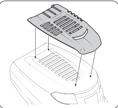
5. Install the hood scoop onto the hood of the tractor and secure from the underside using the four screws removed in Step 2.
OPERATION
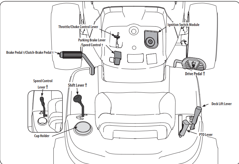
Now that you have set up your riding mower, it’s important to become acquainted with its controls and features.
NOTE: References to LEFT, RIGHT, FRONT, and REAR indicate that position on the riding mower when facing forward while seated in the operator’s seat.
Throttle/Choke Control Lever

- The throttle/choke control lever is located on the left side of the lawn tractor’s dash panel. This lever controls the speed of the engine, as well as the choke when it is pushed all the way forward. When set in a given position, the throttle will maintain a uniform engine speed.
- IMPORTANT: When operating the lawn tractor with the cutting deck engaged, be certain that the throttle/choke control lever is always in the FAST (rabbit) position.
- Moving the throttle/choke control lever all the way forward activates the engine’s choke control. Activating the choke control closes the choke plate on the carburetor and aids in starting the engine.
- Refer to Starting the engine for detailed starting instructions.
Speed Control Lever
Hydrostatic Models
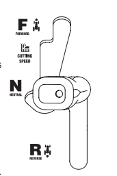
- The speed control lever, located on the left rear fender, controls the ground speed of the lawn tractor as well as the direction of travel.
- To drive forward or in reverse, slowly move the speed control lever to the desired “F” forward or “R” reverse speed.
- To stop, move the speed control lever to the “N” neutral position.
- When mowing, place the speed control lever in the “Cutting Speed” position, or a slower forward speed for the best results.
- NOTE: Do notuse the parking brake pedal to control the ground speed of the lawn tractor. Always use the speed control lever to slow the ground speed of the lawn tractor. Depressing the parking brake pedal with the speed control lever engaged as part of regular operation will result in premature wear of the drive belt.
- IMPORTANT: Do not attempt to change the direction of travel when the lawn tractor is in motion. Serious damage to the lawn tractor’s transmission could result. Always bring the lawn tractor to a complete stop before moving the speed control lever from forward to reverse or vice versa.
CVT

- The speed control lever, located on the lower left side of the lawn tractor’s dash console, allows you to regulate the ground speed of the lawn tractor.
- To use, depress the clutch-brake pedal and move the lever out of the parking brake notch and forward to increase the lawn tractor’s ground speed. When a desired speed has been reached, release the lever into an appropriate notch to maintain that speed.
- To slow the lawn tractor’s ground speed, depress the clutch-brake pedal and move the speed control lever rearward and release it into a notch
Parking Brake Pedal & Lever (If equipped)

- The parking brake pedal is located on the left side running board of the lawn tractor. It is used to set the parking brake and to stop the lawn tractor in sudden situations. The parking brake lever is located on the left side of the lawn tractor’s dash panel.
- To set the parking brake: Fully depress the parking brake pedal. Move the parking brake lever all the way down and into the parking brake position (PARK BRAKE ON) and then release the brake pedal to allow the parking brake to engage.
- To release the parking brake: Depress the brake pedal and the parking brake lever will automatically move out of the parking brake position. In a sudden situation, fully depress the brake pedal to bring the lawn tractor to a stop and then immediately move the speed control lever to the “N” neutral position.
- IMPORTANT: Do not use the parking brake pedal to control the ground speed of the lawn tractor. Doing so will result in premature wear of drive belt. Always use the speed control lever to control the ground speed of the lawn tractor and to stop the lawn tractor under normal circumstances.
- NOTE: The parking brake pedal must be depressed to start the engine. The parking brake must also be set if the operator leaves the seat with the engine running or the engine will automatically shut OFF. Refer to Safety Interlock Switches
Clutch-Brake Pedal (If equipped)
- The clutch-brake pedal is located on the left side of the lawn tractor, along the running board. Depress the clutch-brake pedal part way down when slowing the tractor by changing speeds (Refer to Speed Control Lever). Depress the pedal all the way down to engage the disc brake and bring the tractor to a complete stop.
- NOTE: The pedal must be depressed to start the engine. Refer to Safety Interlock Switches later in this section of this manual.
Shift Lever (CVT & Foot Control CVT Models)
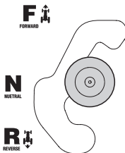
- The shift lever is located on the left side of the fender and has three positions; FORWARD (F), NEUTRAL (N) and REVERSE (R). The brake pedal must be depressed and the lawn tractor must not be in motion when moving the shift lever.
- IMPORTANT: Never force the shift lever. Doing so may result in serious damage to the lawn tractor’s transmission
Drive Pedal (If equipped)
- The drive pedal is located on the right side of the lawn tractor, along the running board. Depress the drive pedal forward and the lawn tractor will move in the direction that the shift lever is engaged in. To cause the lawn tractor to travel forward, while at a complete stop, move the shift lever into the FORWARD (F) position. Gradually step on the drive pedal and the lawn tractor will begin to move forward. To move in REVERSE (R), follow the same procedure only move the shift lever into the REVERSE (R) position.
- The ground speed is controlled with the drive pedal. The further forward that the pedal is pivoted, the faster the lawn tractor will travel. The pedal will return to its original position when it’s not depressed. Refer to Driving the Lawn Tractor for detailed instructions regarding the drive pedal.
- IMPORTANT: Always set the parking brake when leaving the lawn tractor unattended
Headlights
The headlights are located on the front of the lawn tractor.
- On some models, the lamps are ON when the lawn tractor’s engine is running.
- On some models, the lamps are ON whenever the ignition key is moved out of the STOP position.
- On all models, the lamps turn OFF when the ignition key is moved to the STOP position
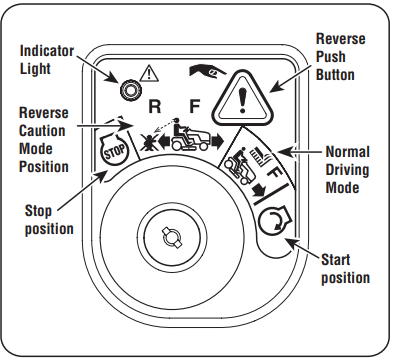
Ignition Switch Module
- To start the engine, insert the key into the ignition switch and turn clockwise to the START position. Release the key into the NORMAL MOWING MODE position once the engine has fired. The headlights will be activated in the NORMAL (and REVERSE CAUTION MODES).
- To stop the engine, turn the key counter-clockwise to the OFF or STOP position
- WARNING: Never leave a running machine unattended. Always disengage PTO, move shift lever into neutral position, set parking brake, stop engine and remove key to prevent unintended starting.
- IMPORTANT: Prior to operating the lawn tractor, refer to both Safety Interlock Switches and Starting The Engine in the Operation section of this manual for detailed instructions regarding the Ignition Switch Module and operating the lawn tractor in REVERSE CAUTION MODE.
Deck Lift Lever
- The deck lift lever is located on the lawn tractor’s right fender. It is used to change the height of the cutting deck. To use, move the lever to the left, then place in the position best suited for your application.
PTO Lever

- The PTO Lever is located on the lawn tractor’s right fender. It is used to engage power to the cutting deck or other optional attachments. To operate, move the lever all the way forward. Moving the lever all the way rearward into the PTO OFF position disengages power to the cutting deck or attachment.
- NOTE: The PTO lever must be in the disengaged (OFF) position when starting the engine
Safety Interlock Switches
This lawn tractor is equipped with a safety interlock system for the protection of the operator. If the interlock system malfunctions, do not operate the lawn tractor. Contact an authorized service dealer.
- The safety interlock system prevents the engine from cranking or starting unless the parking brake is engaged, and the PTO lever is in the disengaged (OFF) position.
- The engine will automatically shut OFF if the operator leaves the seat before engaging the parking brake.
- The engine will automatically shut OFF if the operator leaves the lawn tractor’s seat with the PTO lever in the engaged (ON) position, regardless of whether the parking brake is engaged.
- With the ignition key in the NORMAL DRIVING MODE position, the engine will automatically shut OFF if the PTO lever is moved into the engaged (ON) position with the speed control in REVERSE (R) position.
WARNING: Do not operate the lawn tractor if the interlock system is malfunctioning. This system was designed for your safety and protection.
Reverse Caution Mode
WARNING Use extreme caution while operating the lawn tractor in the REVERSE CAUTION MODE. Always look down and behind before and during lawn tractor backing. Do not operate the lawn tractor when children or others are around. Stop the lawn tractor immediately if someone enters the area.
The REVERSE CAUTION MODE position of the ignition switch module allows the lawn tractor to be operated in reverse with the blades (PTO) engaged.
IMPORTANT: Mowing in the reverse direction is not recommended.
To use the REVERSE CAUTION MODE: IMPORTANT: The operator MUST be seated in the lawn tractor seat.
1. Start the engine as instructed
2. Turn the key from the NORMAL DRIVING MODE (Green) position to the REVERSE CAUTION MODE (Yellow) position of the ignition switch module
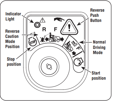
3. Depress the REVERSE PUSH BUTTON (Orange, Triangular Button) at the top, right corner of the ignition switch module. The red indicator light at the top, left corner of the ignition switch module will be ON while activated.
Once activated (indicator light ON), the lawn tractor can be driven in reverse with the cutting blades (PTO) engaged.
5. Always look down and behind before and while backing to make sure no children are around.
6. After resuming forward motion, return the key to the NORMAL DRIVING MODE position. IMPORTANT: The REVERSE CAUTION MODE will remain activated until:
- The key is placed in either the NORMAL DRIVING MODE position or STOP position.
- The operator engages the parking brake by fully depressing the brake pedal and holding it down while moving the parking brake lever into the PARK BRAKE position.
Engaging the Parking Brake
- Fully depress the brake pedal/clutch-brake pedal and hold it down with your foot.
- Move the parking brake lever all the way down and into the ON position.
- Release the brake pedal/clutch-brake pedal to allow the parking brake to engage.
Releasing the Parking Brake: Depress the brake pedal/clutch-brake pedal and move the parking brake lever out of the ON position and into the OFF position.
Setting the Cutting Height
- Select the height position of the cutting deck by placing the deck lift lever in any of the five different cutting height notches on the right side of the fender.
- Adjust the deck wheels, if equipped, so that they are between ¼” and ½” above the ground when the lawn tractor is on a smooth, flat surface such as a driveway.
WARNING: Keep hands and feet away from the discharge opening of the cutting deck
NOTE: On models so equipped, the deck wheels are an anti-scalp feature of the deck and are not designed to support the weight of the cutting deck.
NOTE: Refer to Leveling the Deck for more detailed instructions regarding various deck adjustments.
Starting the Engine
WARNING Do not operate the lawn tractor if the interlock system is malfunctioning. This system was designed for your safety and protection. NOTE: Refer to Gas & Oil fill-up instructions
- Insert the key into the ignition switch.
- Place the PTO lever in the disengaged (PTO OFF) position.
- Engage the lawn tractor’s parking brake (if equipped).
- Activate the choke control.
- Turn the key clockwise to the START position. After the engine starts, release the key. It will return to the PTO ON (or NORMAL DRIVING MODE) position. IMPORTANT: Do NOT hold the key in the START position for longer than 10 seconds at a time. Doing so may cause damage to your engine’s electric starter.
- After the engine starts, deactivate the throttle/choke control lever and place the throttle/choke control lever in the FAST position. NOTE: Do NOT leave the choke control on while operating the lawn tractor. Doing so will result in a “rich” fuel mixture and cause the engine to run poorly.
Stopping the Engine
WARNING: If you strike a foreign object, stop the engine, disconnect the spark plug wire(s) and ground against the engine. Thoroughly inspect the machine for any damage. Repair the damage before restarting and operating.
- If the blades are engaged, place the PTO lever in the disengaged (OFF) position.
- Turn the key counter-clockwise to the STOP position.
- Remove the key from the ignition switch to prevent unintended starting.
Driving the Lawn Tractor
- IMPORTANT: First-time operators should become completely familiar with the lawn tractor’s operation and controls before operating the lawn tractor in higher speed positions.
- WARNING: Always look down and behind before and while traveling in reverse to avoid a back-over accident.
- WARNING: Before leaving the operator’s position, place the PTO lever in the disengaged (PTO OFF) position, place speed control lever in NEUTRAL (N), set parking brake, stop engine and remove key to prevent unintended starting. Depress the parking brake pedal to release the parking brake and let the pedal up.
Hydrostatic
- Move the throttle lever into the FAST (rabbit) position. NOTE: Always operate the lawn tractor with the throttle control lever in the FAST (rabbit) position for the most efficient use of the cutting deck or other (separately available) attachments.
- Depress the parking brake pedal to release the parking brake.
- Slowly move the speed control lever in desired FORWARD (F) or REVERSE (R) position. The further forward or rearward that the lever is moved, the faster the lawn tractor will travel. WARNING: Do NOT attempt to change the direction of travel when the lawn tractor is in motion. Always bring the lawn tractor to a complete stop before moving the speed control lever from forward to reverse or vice versa. Failure to do so could result in serious damage to your lawn tractor’s transmission. IMPORTANT: First-time operators should use slower speeds. Become completely familiar with the lawn tractor’s operation and controls before operating the lawn tractor at higher speed.
- To stop, move the speed control lever to the NEUTRAL (N) position. IMPORTANT: In a sudden situation, fully depress the brake pedal to bring the lawn tractor to a stop and then immediately move the speed control lever to the “N” neutral position.
- Set the parking brake by fully depressing the parking brake pedal and keeping it depressed while placing the parking brake lever in the ON position. Release the parking brake pedal to allow the parking brake to engage.
WARNING: Before leaving the operator’s position for any reason, disengage the blades, place the speed control lever in neutral, engage the parking brake, shut engine OFF and remove the key.
CVT
- Depress the clutch-brake pedal to release the parking brake and let the pedal up.
- Move the throttle lever into the FAST (rabbit) position.
- Place the shift lever in either the FORWARD (F) or REVERSE (R) position. WARNING Do NOT use the shift lever to change the direction of travel when the lawn tractor is in motion. Always use the clutch-brake pedal to bring the lawn tractor to a complete stop before shifting.
- Release the parking brake by depressing the clutch-brake pedal and positioning the speed control lever in desired position. IMPORTANT: First-time operators should use speed positions 1 or 2. Become completely familiar with the lawn tractor’s operation and controls before operating the lawn tractor in higher speed positions.
- Release clutch-brake pedal slowly to put unit into motion.
- The lawn tractor is brought to a stop by depressing the clutch-brake pedal. NOTE: When operating the unit initially, there will be little difference between the highest two speeds until after the belts have seated themselves into the pulleys during the break-in period.
WARNING: Before leaving the operator’s position for any reason, disengage the blades, place the shift lever in neutral, engage the parking brake, shut engine OFF and remove the key.
If unit stalls with speed control in high speed, or if unit will not operate with speed control lever in a low speed position, proceed as follows:
- Place shift lever in NEUTRAL (N).
- Restart engine.
- Place speed control lever in highest speed position.
- Release clutch-brake pedal fully.
- Depress clutch-brake pedal.
- Place speed control lever in desired position.
- Place shift lever in either FORWARD (F) or REVERSE (R), and follow normal operating procedures.
Foot Control CVT
- Depress the brake pedal to release the parking brake and let the pedal up.
- Move the throttle lever into the FAST (rabbit) position.
- Place the shift lever in either the FORWARD (F) or REVERSE (R) position. WARNING Do NOT use the shift lever to change the direction of travel when the lawn tractor is in motion. Always use the clutch-brake pedal to bring the lawn tractor to a complete stop before shifting.
- Gradually begin to apply pressure to the drive pedal. The further down the pedal is pushed, the faster the lawn tractor will travel in the desired direction based on the position of the shift lever.
- The lawn tractor is brought to a stop by releasing the drive pedal and then depressing the brake pedal.
WARNING: Before leaving the operator’s position for any reason, disengage the blades, place the shift lever in NEUTRAL (N), engage the parking brake, shut engine OFF and remove the key
Parking the Lawn Tractor
IMPORTANT: When stopping the lawn tractor for any reason while on a grass surface:
- Place the speed control lever/shift lever in N (neutral),
- Engage the parking brake.
- Shut engine OFF and remove the key. Doing so will minimize the possibility of having your lawn “browned” by hot exhaust from your lawn tractor’s running engine
Driving On Slopes
Refer to the SLOPE GAUGE to help determine slopes where you may operate the lawn tractor safely.
WARNING: Do not mow on inclines with a slope in excess of 15 degrees (a rise of approximately 2-1⁄2 feet every 10 feet). The lawn tractor could overturn and cause serious injury.
- Mow up and down slopes, NEVER across.
- Exercise extreme caution when changing direction on slopes.
- Watch for holes, ruts, bumps, rocks, or other hidden objects. Uneven terrain could overturn the machine. Tall grass can hide obstacles.
- Avoid turns when driving on a slope. If a turn must be made, turn down the slope. Turning up a slope greatly increases the chance of a roll over.
- Avoid stopping when driving up a slope. If it is necessary to stop while driving up a slope, start up smoothly and carefully to reduce the possibility of flipping the lawn tractor over backward.
Engaging the Blades
Engaging the PTO (blade engage) transfers power to the cutting deck. To engage the blades, proceed as follows:
- Move the throttle control lever to the FAST (rabbit) position.
- Grasp the PTO lever and pivot it all the way forward into the engaged (PTO ON) position.
- Keep the throttle lever in the FAST (rabbit) position for the most efficient use of the cutting deck or other optional attachments.
IMPORTANT: Models with REVERSE CAUTION MODE: The engine will automatically shut OFF if the PTO is engaged with the speed control lever in position for reverse travel with the key in the NORMAL DRIVING MODE position.
IMPORTANT: Models without REVERSE CAUTION MODE: The PTO lever must be in the disengaged (PTO OFF) position when starting the engine, when traveling in reverse, and if the operator leaves the seat. Refer to Safety Interlock Switches
Using the Deck Lift Lever
- To raise the cutting deck, move the deck lift lever to the left, then place it in the notch best suited for your application. Refer to Setting the Cutting Height
Mowing
WARNING: To help avoid blade contact or a thrown object injury, keep bystanders, helpers, children and pets at least 75 feet from the machine while it is in operation. Stop machine if anyone enters the area.
The following information will be helpful when using the cutting deck with your lawn tractor:
WARNING: Plan your mowing pattern to avoid discharge of materials toward roads, sidewalks, bystanders and the like. Also, avoid discharging material against a wall or obstruction which may cause discharged material to ricochet back toward the operator.
- Do not mow at high ground speed, especially if a mulch kit or grass collector is installed.
- For best results it is recommended that the first two laps be cut with the discharge thrown towards the center. After the first two laps, reverse the direction to throw the discharge to the outside for the balance of cutting. This will give a better appearance to the lawn.
- Do not cut the grass too short. Short grass invites weed growth and yellows quickly in dry weather.
- Mowing should always be done with the engine at full throttle.
- Under heavier conditions it may be necessary to go back over the cut area a second time to get a clean cut.
- Do NOT attempt to mow heavy brush and weeds and extremely tall grass. Your lawn tractor is designed to mow lawns, NOT clear brush.
- Keep the blades sharp and replace the blades when worn. Refer to Cutting Blades on page 27 for proper blade sharpening instructions.
SERVICE AND MAINTENANCE
MAINTENANCE SCHEDULE
WARNING: Before performing any type of maintenance/service, disengage all controls and stop the engine. Wait until all moving parts have come to a complete stop. Disconnect spark plug wire and ground it against the engine to prevent unintended starting. Always wear safety glasses during operation or while performing any adjustments or repairs.
Follow the maintenance schedule given below. This chart describes service guidelines only. Use the Service Log column to keep track of completed maintenance tasks. To locate the nearest Parts & Repair Service Center or to schedule service
Refer to the Engine Operator’s Manual for the engine maintenance items listed in the table below.
1. Each Use
- Engine Intake Screens & Cooling Fans *
- Check/Clean (See engine manual)
- Exhaust Manifold, Muffler Pipe & Muffler Shields *
- Hood/Dash Panel Louvers *
- Top & Underside of Deck, Under and Around Spindle Covers & Belt Area *
- Around Fuses, Wiring and Wiring Harnesses *
- Around Transmission, Axle and Fans *
2. After First Five Hours
- Engine Oil
- Change (See engine manual)
3. Every 10 Hours
- Hood/Dash air vents
- Battery terminals
- Pedal pivot points
4. Every 25 hours
- Axles and Rims
- Engine Cooling fans
- Air filter’s prefilter*
- Clean (See engine manual)
- Air filter*
- Clean (See engine manual)
5. Every 50 hours
- Belts and pulleys
- Check for damage and wear
- Engine Oil
- Change (See engine manual)
- Oil Filter
- Replace (See engine manual)
- Air Filter
- Clean or change (See engine manual)
- Fuel Filter
- Replace (See engine manual)
6. Every 100 hours
- Hardware
- Spark plug condition/gap
- Check (See engine manual)
7. Before Storage
- Hood/Dash air vents
- Battery terminals
- Pedal pivot points
- Axles and rims
- Engine cooling fans
- Lubrication points
- Blades
- Check/Sharpen/Replace as needed
- Tires
- Front wheels
- Deck
- Deck wheels
- Deck level/pitch
- Deck spindles
- Spark plug condition/gap
- Check (See engine manual)
- Engine Oil
- Change (See engine manual)
- Oil Filter
- Replace (See engine manual)
*-- Perform more often in dry conditions and/or when mulching
Maintenance
WARNING: Before performing any maintenance or repairs, disengage PTO, move shift lever into neutral position, set parking brake, stop engine and remove key to prevent unintended starting.
WARNING: If the engine has been recently run, the engine, muffler and surrounding metal surfaces will be hot and can cause burns to the skin. Exercise caution to avoid burns.
Post-Operation Rider Care
- After each operation of the rider, the following procedures should be implemented to extend the life of your rider and ensure safe operating conditions.
- DANGER: Failure to follow these recommendations may result in serious injury to yourself or others and may cause damage to the rider.
Cleaning the Underside of the Deck - Deck Wash System (If equipped): Some tractors come fitted with a Deck Wash System, which is used to rinse grass clippings from the deck’s underside and prevent the buildup of corrosive chemicals. Other tractors may have a deck wash plug, allowing for a Deck Wash System that can be added at a later time. If this is the case, a hex bolt and washer can be found on your tractor’s deck surface and can be replaced with a water port to be used as part of an optional deck wash system. Use the deck wash system to rinse grass clippings from the deck’s underside and prevent the buildup of corrosive chemicals. Complete the following steps AFTER EACH MOWING:
1. Drive the rider to a level, clear spot on your lawn, near enough for your garden hose to reach. WARNING: Make certain the rider’s discharge chute is directed AWAY from people, your house, garage, parked cars, etc.
2. Disengage the PTO, set the parking brake and stop the engine.
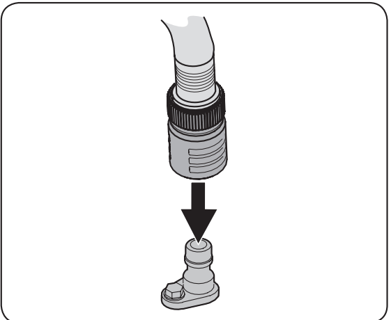
3. Thread the hose coupler (packaged with your rider’s Operator’s Manual) onto the end of your garden hose.
4. Attach the hose coupler to the water port on your decks surface.
Note: Make sure that the hose is not routed under the deck and is clear of all moving parts.
5. Turn the water on.
6. While sitting in the operator’s position on the rider, start the engine and place the throttle lever in the FAST  position.
7. Move the rider’s PTO into the engaged (ON) position. 8. Remain in the operator’s position with the deck engaged for a minimum of two minutes, allowing the underside of the deck to thoroughly rinse.
9. Move the rider’s PTO into the disengaged (OFF) position.
10. Turn the ignition key to the STOP  position to turn the rider’s engine off.
11. Turn the water off and detach the hose coupler from the water port on your deck’s surface. Note: On 50” and 54” decks there are two water ports; one on each side of the deck.
12. After cleaning your deck with the Smart Jet system, return to the operator’s position and engage the PTO. Keep the deck running for a minimum of two minutes, allowing the underside of the deck to thoroughly dry
Cleaning the Rider
WARNING: If the rider has been recently run, the engine, muffler and surrounding metal surfaces will be hot and can cause burns to the skin. Let the engine cool for at least five minutes Exercise caution to avoid burns.
Your rider should be cleaned after each use and under certain conditions, i.e. dry conditions and/or mulching situations, additional cleaning may be necessary.
One of the best ways to keep your rider running efficiently and to reduce fire risk is to regularly remove debris buildup from the rider. Follow the recommendations below and contact your authorized dealer with any questions.
- Allow the machine to cool in an open area before cleaning.
- Do not use water on any part of the rider except the underside of the cutting deck. Doing so can cause damage to the rider’s spindle bearings, electrical system and engine, leading to premature failures. The use of compressed air and/or leaf blower will help keep the rider clean.
- Clean under the hood. Exhaust manifold, around fuses, all wiring and harnesses, muffler pipe, muffler shield, engine intake screens and cooling fins, etc.
- Clean the top of the mower deck, under the spindle covers and belt area
- Clean around and near the transmission, axle and the fan area

- Debris can accumulate anywhere on the rider, especially on horizontal surfaces. Additional cleaning may be necessary when mowing in dry conditions or when mulching.
- Fuel leaks/spills, oil leaks/spills and excess lubrication can also become collections sites for debris. Immediate repair and cleaning up oil or fuel spills can help reduce fire hazards.
- In addition to cleaning the rider before operating and storing, do not attempt to mow unusually tall grass (10” or higher), dry grass (e.g., pasture) or piles of dry leaves. Dry grass or leaves may contact the engine exhaust and/or build up on the mower deck presenting a potential fire hazard.
Engine
Refer to the Engine Operator’s Manual for engine maintenance instructions.
Check engine oil level before each use as instructed in the Engine Operator’s Manual. Follow the instructions carefully.
Changing Engine Oil - Oil Drain Hose Models: WARNING: If the engine has been recently run, the engine, muffler and surrounding metal surfaces will be hot and can cause burns to the skin. Exercise caution to avoid burns. NOTE: The oil filter (if equipped) should be changed at every oil change interval. To complete the oil change, proceed as follows:
- Run the engine for a few minutes to allow the oil in the crankcase to warm. Warm oil will flow more freely and carry away more of the engine sediment which may have settled at the bottom of the crankcase. Use care to avoid burns from hot oil.
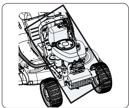
- Open the tractor’s hood and locate the oil drain port on the left side of the engine.
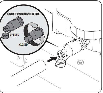
- Open the protective cap on the end of the oil drain valve to expose the drain port.
- Remove the oil fill cap/dipstick from the oil fill tube.
- Push the oil drain hose (provided) onto the oil drain port. Route the opposite end of the hose into an appropriate oil collection container with at least a 2.5 quart capacity, to collect the used oil.
- Slightly push in on the oil drain valve and rotate counter-clockwise to open and allow the flow of oil.
- After the oil has finished draining, push the oil drain valve back in and rotate into the locked position. Re-cap the end of the oil drain valve to keep debris from entering the drain port.
- Replace the oil filter (if equipped) as instructed in the Engine Operator’s Manual.
- Refill the engine with new oil. Refer to the Engine Operator’s Manual for information regarding the proper quantity and viscosity of engine oil.
Oil Drain Sleeve Models
WARNING: If the engine has been recently run, the engine, muffler and surrounding metal surfaces will be hot and can cause burns to the skin. Exercise caution to avoid burns. To complete the oil change, proceed as follows:
- Run the engine for a few minutes to allow the oil in the crankcase to warm. Warm oil will flow more freely and carry away more of the engine sediment which may have settled at the bottom of the crankcase. Use care to avoid burns from hot oil.
- Open the tractor’s hood and locate the oil drain port on the left side of the engine.
- Unscrew the oil fill cap and remove the dipstick from the oil fill tube.
- Snap the small end of oil drain sleeve onto the oil sump
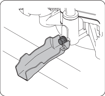
- Remove drain plug and drain oil into a suitable container with a capacity of no less than 64 oz.
- Service oil filter (if equipped) as instructed in the separate Engine Operator’s Manual.
- Perform the previous steps in the opposite order after oil has finished draining.
- Refill the engine with new oil. Refer to the Engine Operator’s Manual for information regarding the proper quantity and viscosity of engine oil.
Lubrication
- WARNING: Before lubricating, repairing, or inspecting, always disengage PTO, move shift lever into neutral position, set parking brake, stop engine and remove key to prevent unintended starting.
- Engine: Lubricate the engine with motor oil as instructed in the Engine Operator’s Manual.
- Pivot Points & Linkage: Lubricate all the pivot points on the drive system, parking brake and deck lift linkage at least once a season with light oil.
- Rear Wheels: The rear wheels should be removed from the axles once a season. Lubricate the axles and the rims with an all-purpose grease before re-installing them.
- Front Axles (Hydrostatic only): Each end of the tractor’s front pivot bar may be equipped with a grease fitting. Lubricate with a grease gun after every 25 hours of tractor operation.
Headlights
Replace headlight bulbs as follows:
- Fully raise the hood of the tractor.
- Unplug the wire harness leads from the headlight socket terminals. Note which wire connects to each terminal before disconnecting.
- Rotate the socket assembly approximately a 1⁄4-turn to align the socket tab with the reflector housing notch; then withdraw the bulb and socket assembly from the reflector housing
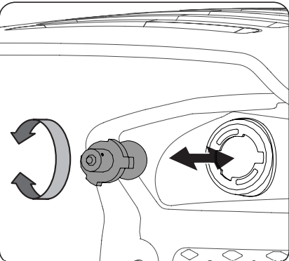
- Push the bulb inward and turn counter-clockwise to remove from the socket.
- Align a locking post of the bulb base with the notch in the socket, then push the bulb inward and turn clockwise to lock.
- Align the socket tab with the notch of the reflector housing; then push the socket inward and turn as necessary to lock the socket in the housing.
- Connect the wire harness leads to the appropriate socket terminals.
Cleaning the Engine
- Any fuel or oil spilled on the machine should be wiped off promptly. Do NOT allow debris to accumulate around the cooling fins of the engine or on any other part of the machine.
- IMPORTANT: The use of a pressure washer to clean your tractor is NOT recommended. It may cause damage to electrical components, spindles, pulleys, bearings or the engine.
Battery
WARNING: CALIFORNIA PROPOSITION 65 WARNING! Battery posts, terminals, and related accessories contain lead and lead compounds, chemicals known to the State of California to cause cancer and reproductive harm. Wash hands after handling.
CAUTION: If removing the battery, disconnect the NEGATIVE (Black) wire from its terminal first, followed by the POSITIVE (Red) wire. When re-installing the battery, always connect the POSITIVE (Red) wire to its terminal first, followed by the NEGATIVE (Black) wire.
The battery is sealed and is maintenance-free. Acid levels cannot be checked.
- Always keep the battery cables and terminals clean and free of corrosive build-up.
- After cleaning the battery and terminals, apply a light coat of petroleum jelly or grease to both terminals.
- Always keep the rubber boot positioned over the positive terminal to prevent shorting.
IMPORTANT: Be certain that the wires are connected to the correct terminals; reversing them could change the polarity and result in damage to your engine’s alternating system.
Cleaning Battery: Clean the battery by removing it from the tractor and washing with a baking soda and water solution. If necessary, clean the battery terminals with a wire brush to remove deposits. Coat terminals and exposed wiring with a light coat of petroleum jelly or grease to both terminals prevent corrosion.
Battery Failures - Some common causes for battery failure are:
- Incorrect initial activation
- Overcharging
- Freezing
- Undercharging
- Corroded connections
NOTE: These failures are NOT covered by your tractor’s warranty.
Charging
- WARNING: Batteries emit an explosive gas while charging. Charge the battery in a well ventilated area and keep away from an open flame or pilot light as on a water heater, space heater, furnace, clothes dryer or other gas appliances.
- CAUTION: When charging your tractor’s battery, use only a charger designed for 12V leadacid batteries. Read your battery charger’s Owner’s Manual prior to charging your tractor’s battery. Always follow its instructions and heed its warnings.
- If your tractor has not been put into use for an extended period of time, charge the battery as follows: Set your battery charger to deliver a max of 10A. If your battery charger is automatic, charge the battery until the charger indicates that charging is complete. If the charger is not automatic, charge for a minimum of eight hours.
Jump Starting
WARNING: Never jump start a damaged or frozen battery. Be certain the vehicles do not touch, and ignitions are OFF. Do not allow cable clamps to touch.
IMPORTANT: Never jump start your lawn tractor’s battery with the battery of a running vehicle.
- Connect positive (+) cable to positive post (+) of your lawn tractor’s discharged battery.
- Connect the other end of the cable to the (positive +) post of the jumper battery.
- Connect the second cable (negative –) to the other post of the jumper battery.
- Make the final connection on the engine block of the tractor, away from the battery. Attach to a unpainted part to ensure a good connection. CAUTION If the jumper battery is installed on a vehicle (i.e. car, truck), do NOT start the vehicle’s engine when jump starting your lawn tractor.
- Start the tractor as instructed
- Set the tractor’s parking brake before removing the jumper cables, in reverse order of connection.
WARNING: Failure to properly jump start the battery could cause a spark, and the gas in either battery could explode.
Removing the Battery: To remove the battery, pull outward and then up on the battery hold-down bracket.
Fuse
- One 20A fuse is installed in your tractor’s wiring harness to protect the tractor’s electrical system from damage caused by excessive amperage.
- If the electrical system does not function, or your tractor’s engine will not crank, check that the fuse has not blown. It can be found at the rear of the unit, underneath the fender located by the battery.
- WARNING: Always use a fuse with the same amperage capacity for replacement.
Leveling the Deck
NOTE: Check the tractor’s tire pressure before performing any deck leveling adjustments. Refer to Tires for more information regarding tire pressure.
Front-to- Rear: The front of the cutting deck is supported by a stabilizer bar that can be adjusted to level the deck from front to rear. The front of the deck should be between ¼” and 3⁄8” lower than the rear of the deck. Adjust if necessary as follows:
- With the tractor parked on a firm, level surface, place the lever for lifting the platform on the second to the top notch (second highest position) and rotate the blade as close to the discharge channel that is parallel to the tractor.
- Measure the distance from the front of the blade tip to the ground and the rear of the blade tip to the ground. The first measurement taken should be between ¼” and 3⁄8” less than the second measurement. Determine the approximate distance necessary for proper adjustment and proceed, if necessary, to the next step
- Locate the jam nut and lock nut on the front side of the stabilizer bracket.
- After loosening the jam nut:
- Tighten the lock nut to raise the front of the deck;
- Loosen the lock nut to lower the front of the deck.
- Retighten the jam nut loosened earlier when proper adjustment is achieved.
Side-to-Side: If the cutting deck appears to be mowing unevenly, a side-to-side adjustment can be performed. Adjust if necessary as follows:
- With the tractor parked on a firm, level surface, place the deck lift lever in the second notch from the top (second highest position) and rotate both blades so that they are perpendicular with the tractor.
- Measure the distance from the outside of the left blade tip to the ground and the distance from the outside of the right blade tip to the ground. Both measurements taken should be equal. If they’re not, proceed to the next step
- Loosen, but do NOT remove, the hex cap screw (a) on the left deck hanger bracket
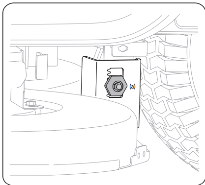
- Balance the deck by using a wrench to turn the adjustment gear (found immediately behind the hex cap screw just loosened) clockwise/up or counter-clockwise/down. The deck is properly balanced when both blade tip measurements taken earlier are equal.
- Retighten the hex cap screw (a) on the left deck hanger bracket when proper adjustment is achieved
Seat Adjustment
- Refer to Attaching the Seat for seat adjustment instructions.
Parking Brake Adjustment
- WARNING: Never attempt to adjust the brakes while the engine is running. Always disengage PTO, move shift lever into neutral position, stop engine and remove key to prevent unintended starting.
- If the tractor does not come to a complete stop when the brake pedal is completely depressed, or if the tractor’s rear wheels can roll with the parking brake applied, the brake is in need of adjustment. See an authorized service dealer to have your brakes properly adjusted.
Cutting Deck Removal: To remove the cutting deck, proceed as follows:
- Place the PTO lever in the disengaged (OFF) position and engage the parking brake.
- Lower the deck by moving the deck lift lever into the bottom notch on the right fender.
- Remove the belt-keeper rod (a), from around the tractor’s engine pulley, by removing the self-tapping screw (b) that secures it.
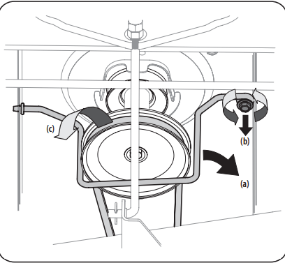 NOTE: Make a note what hole the other end of the belt-keeper rod is inserted in for reinstallation purposes.
- Remove the belt (c) from around the tractor’s engine pulley and idler pulley(s).
- Looking at the cutting deck from the left side of the tractor, locate the bow-tie pin (a) that secures the deck support rod (b) on the rear left side of the deck. . Remove the bow-tie pin (a) that secures the deck support rod (b), and carefully remove the deck support from the deck lift arm.
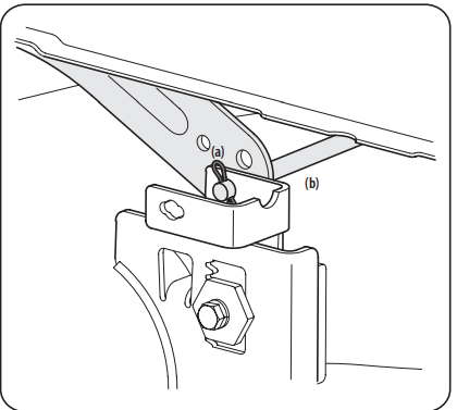
- Repeat step 5 on the tractor’s right side
- Move the deck lift lever into the top notch on the right fender to raise the deck lift arms up and out of the way.
- Remove the bow-tie pin (a) securing the deck stabilizer rod (b) to the deck. Slide the deck lift rod from the mounting weldment on the deck as seen
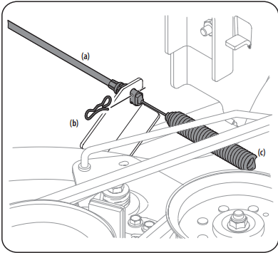
- Carefully remove the PTO cable (a) from the rear of the cutting deck by removing the bow-tie clip (b) which secures it. Remove the spring (c) from the deck idler bracket.
- Gently slide the cutting deck (from the left side) out from underneath the tractor.
Cutting Deck Installation
- To install the deck, reverse the Deck Removal instructions
Tires
WARNING Never exceed the maximum inflation pressure shown on the sidewall of the tire.
The recommended operating tire pressure is:
- Approximately 10 psi for the rear tires
- Approximately 14 psi for the front tires
IMPORTANT: Refer to the tire sidewall for exact tire manufacturer’s recommended or maximum psi. Do not overinflate. Uneven tire pressure could cause the cutting deck to mow unevenly.
Cutting Blades
WARNING: Shut the engine OFF and remove the key before removing the cutting blade(s) for sharpening or replacement. Protect your hands by using heavy gloves when grasping the blade.
WARNING: Periodically inspect the blade spindles for cracks or damage, especially if you strike a foreign object. Replace immediately if damaged. The blades may be removed as follows:
- Remove the deck from beneath the tractor, (refer to Cutting Deck Removal) then gently flip the deck over to expose its underside.
- Place a block of wood between the center deck housing baffle and the cutting blade to act as a stabilizer.
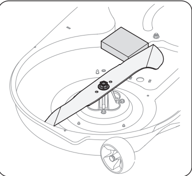
- Remove the hex flange nut that secures the blade to the spindle assembly.
- To properly sharpen the cutting blades, remove equal amounts of metal from both ends of the blades along the cutting edges, parallel to the trailing edge, at a 25° to 30° angle. IMPORTANT: If the cutting edge of the blade has already been sharpened to within 1-5⁄8” from the edge, or if any metal separation is present, replace the blades with new ones
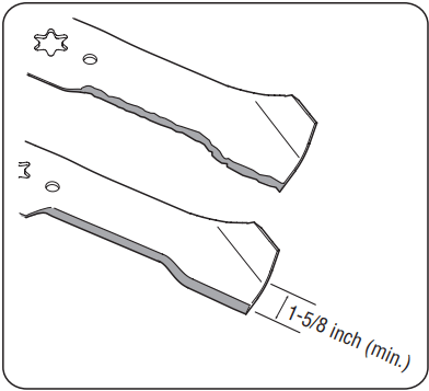
CAUTION: If the cutting edge of the blade has previously been sharpened, or if any metal separation is present, replace the blades with new ones.
WARNING: A poorly balanced blade will cause excessive vibration, may cause damage to the tractor and/or result in personal injury.
Test the blade’s balance using a blade balancer. Grind metal from the heavy side until it balances evenly.
NOTE: When replacing the blade, be sure to install the blade with the side of the blade marked ‘‘Bottom’’ (or with a part number stamped in it) facing the ground when the mower is in the operating position.
CAUTION: Use a torque wrench to tighten the blade spindle hex flange nut to between 70 ft-lbs and 90 ft-lbs.
Changing the Deck Belt
WARNING: Be sure to shut the engine OFF, remove the key, disconnect the spark plug wire(s) and ground against the engine to prevent unintended starting before removing the belt.
WARNING: All belts on your lawn tractor are subject to wear and should be replaced if any signs of wear are present.
IMPORTANT: The V-belt found on your tractor are specially designed to engage and disengage safely. A substitute (non-OEM) V-belt can be dangerous by not disengaging completely. For a proper working machine, use factory approved belts. To change or replace the deck belt on your tractor, proceed as follows:
- Remove the deck. Refer to Cutting Deck Removal
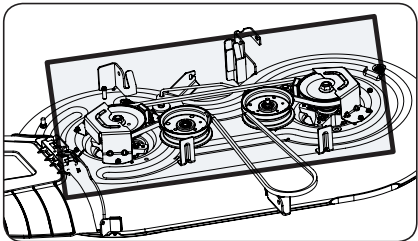
- Remove the belt covers (a) by removing the hex washer screws (b) that fasten them to the deck.
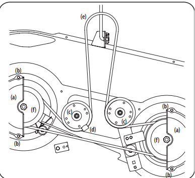
- It may also be necessary to loosen the hex nut on the left idler pulley (c) to get the belt off the pulley and around the belt guard (d).
- arefully remove the deck belt (e) from around the two spindle pulleys (f) and the two deck idler pulleys (c).
- To place the new belt, begin by routing the belt around the two spindle pulleys (f). Route the belt around the two deck idler pulleys (c). Retighten the left idler pulley hex nut loosened in step 3. Remount the belt covers removed (a) in Step 2.
- Re-install the deck, making sure the belt remains routed around the pulleys as instructed.
- Pull the right side of the belt, and place the narrow V side of the belt into the PTO pulley
OFF-SEASON STORAGE
WARNING: Never store lawn tractor with fuel in tank indoors or in poorly ventilated areas where fuel fumes may reach an open flame, spark, or pilot light as on a furnace, water heater, clothes dryer, or gas appliance.
Preparing the Engine
IMPORTANT: Fuel left in the fuel tank during warm weather deteriorates and will cause serious starting problems.
To prevent gum deposits from forming inside the engine’s carburetor and causing possible malfunction of the engine, the fuel system must be either completely emptied, or the gasoline must be treated with a stabilizer to prevent deterioration.
1. If using a fuel stabilizer:
- Read the product manufacturer’s instructions and recommendations.
- Add to clean, fresh gasoline the correct amount of stabilizer for the capacity of the fuel system.
- Fill the fuel tank with treated fuel and run the engine for 2-3 minutes to get stabilized fuel into the carburetor.
2. If emptying the fuel system:
- Do not drain fuel when the engine is hot. Allow the engine adequate time to cool. Drain fuel into an approved container outdoors, away from open flame.
- Drain any large volume of fuel from the tank by disconnecting the fuel line from the in-line fuel filter near the engine. See the complete instructions for Draining The Fuel later in this section. WARNING: Gasoline is extremely flammable and can be explosive under certain conditions. Drain gasoline before storing the equipment for extended periods. Drain fuel only into an approved container outdoors, away from an open flame. Allow engine to cool. Extinguish cigarettes, cigars, pipes, and other sources of ignition prior to draining fuel. Store gasoline in an approved container in safe location.
- Reconnect the fuel line and run the engine until it starts to falter, then use the choke to keep the engine running until all fuel in the carburetor has been exhausted.
- Disconnect the fuel line and drain any remaining gasoline from the system. WARNING: Gasoline is a toxic substance. Dispose of gasoline properly. Contact your local authorities for approved disposal methods.
3. Remove the spark plug and pour one (1) ounce of engine oil through the spark plug hole into the cylinder. Crank the engine several times to distribute the oil. Replace the spark plug.
Draining the Fuel
- Locate the fuel filter, which is located on the left side of the engine, and may be attached to the engine with a tie strap.
- Cut the tie strap, if present, then pinch the in-line clamp on the fuel filter with a pair of pliers, slide the clamp up the fuel line.
- Pull the fuel line free from the filter and place the open end of the line into an approved container to drain the fuel.
Preparing the Lawn Tractor
- Clean and lubricate tractor thoroughly as described in the lubrication instructions.
- Do not use a pressure washer or garden hose to clean your unit.
- Store the mower in a dry, clean area. Do not store next to corrosive materials, such as fertilizer.
TROUBLESHOOTING
WARNING: Before performing any type of maintenance/service, disengage all controls and stop the engine. Wait until all moving parts have come to a complete stop. Disconnect spark plug wire and ground it against the engine to prevent unintended starting. Always wear safety glasses during operation or while performing any adjustments or repairs.
This section addresses minor service issues. To locate the nearest authorized Service Center or to schedule service
1. Engine fails to start
- PTO/Blade Engage lever engaged.
- Place lever in disengaged (OFF) position.
- Parking brake not engaged.
- Spark plug wire(s) disconnected.
- Connect wire(s) to spark plug(s).
- Throttle/Choke control lever not in correct starting position.
- Place Throttle/Choke lever into the FAST position.
- Choke not activated
- Move the Throttle/Choke lever into the Choke position.
- Fuel tank empty, or stale fuel.
- Fill tank with clean, fresh (less than 30 days old) gas.
- Blocked fuel line.
- Replace the fuel line and replace fuel filter.
- Faulty spark plug(s).
- Clean, adjust gap or replace plug(s).
- Engine flooded.
- Crank engine with throttle in FAST position.
- Blown Fuse(s)
- Replace Fuse(s) See “Fuse” in Service and Maintenance section
2. Engine runs erratically
- Unit running with CHOKE activated.
- Spark plug wire(s) loose.
- Connect spark plug wire(s).
- Blocked fuel line or stale fuel.
- Replace the fuel line; fill tank with clean, fresh gasoline and replace fuel filter.
- Vent in gas cap plugged.
- Clear vent or replace cap if damaged.
- Water or dirt in fuel system.
- Drain fuel tank. Refill with clean, fresh gasoline.
- Dirty air cleaner.
- Replace air cleaner paper element or clean foam pre-cleaner, if equipped.
3. Engine overheats
- Engine oil level low.
- Fill crankcase with proper amount and weight of oil.
- Air flow restricted.
- Clean grass clippings and debris from around the engine’s cooling fins and housing
4. Engine hesitates at high RPM
- Spark plug gap too close.
- Remove spark plug and reset the gap.
5. Engine idles rough
- Spark plug fouled, faulty or gap too wide.
- Replace spark plug. Set plug gap.
- Dirty air cleaner.
- Replace air cleaner element and/or clean precleaner
6. Excessive vibration
- Cutting blade loose or unbalanced.
- Tighten blade and spindle.
- Damaged or bent cutting blade.
7. Mower will not mulch grass
- Engine speed too low.
- Place throttle in FAST (rabbit) position.
- Wet grass.
- Do not mulch when grass is wet.
- Excessively high grass.
- Mow once at a high cutting height, then mow again at desired height or make a narrower cutting swath.
- Dull blade.
8. Uneven cut
- Deck not leveled properly.
- Perform side-to-side deck adjustment.
- Dull blade.
- Sharpen or replace blade.
- Uneven tire pressure.
- Check tire pressure in all four tires.