Note: This Operator’s Manual covers several models. Tractor features may vary by model. Not all features in this manual are applicable to all tractor models and the tractor depicted may differ from yours.
Note: All references in this manual to the left or right side and front or back of the tractor are from the operating position only. Exceptions, if any, will be specified. Note: Some components may come already assembled. If they are already assembled, skip ahead to the next step.
Contents of Crate
Tractor
Steering Pedestal Cap
Discharge Chute Assembly
Hardware Pack
Product Registration Card
Operator’s Manual
Rear Hitch Plate
Mulch Plug
Battery Charger
Steering wheel/ Shaft Assembly
Seat Assembly
Seat Assembly
Front Bumper
Battery Charger Manual
Contents of Hardware Pack
Before beginning installation, remove all the contents from the crate and all the hardware from the pack to make sure everything is present. Hardware is listed below.
The tractor can be moved as long as the parking brake is not set. Do not tow the tractor. The tractor can be pushed slowly.
Installing the Steering Wheel Assembly
If the steering wheel assembly for your tractor did not come already installed, follow the steps below:
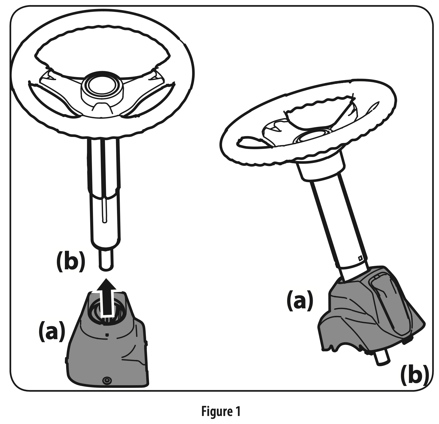
Slide the pedestal cap (a) onto the steering shaft (b) so that when the steering shaft (b) is installed on the tractor, the pedestal cap (a) will be upright as shown in Figure 1.
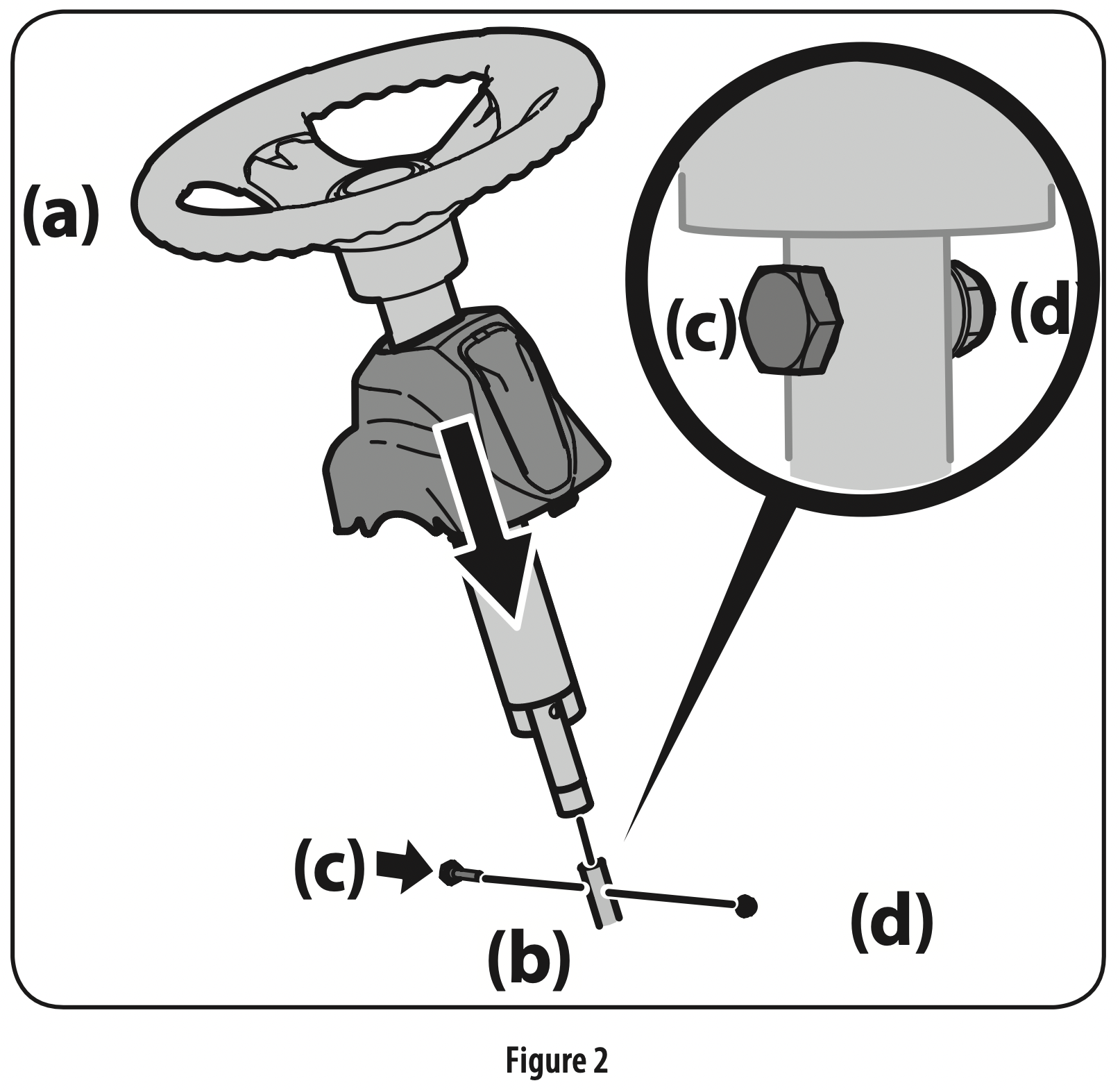
Remove the shoulder bolt (c) and lock nut (d) from the steering shaft and retain for later steps. See Figure 2.
Position the steering wheel assembly over the lower steering shaft on the tractor. Align the steering wheel so that its largest opening faces forward when the tractor wheels are straight.
Lower the steering wheel assembly (a) onto the lower steering shaft (b) and secure with the shoulder bolt (c) and lock nut (d)previously removed. See Figure 2.
Tighten the shoulder bolt and lock nut using a 9/16” wrench or socket and 7/16”wrench or socket.
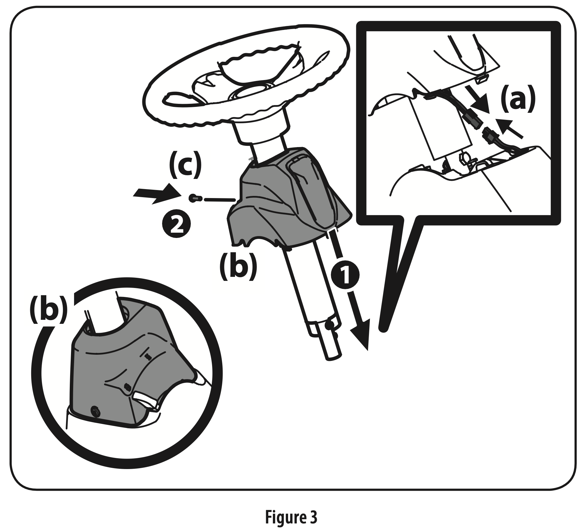
Remove the pedestal cap mount screw factory installed and located on the tractor’s steering console. Retain the screw for later instructions. See Figure 3.
Connect the headlight wire terminals (a). Slide the pedestal cap (b) down onto the tractor and slightly rotate to the right to clip into place. Secure the pedestal cap (b) with the screw (c) previously removed. See Figure 3.
Attaching the Seat
If the seat for your tractor was not attached at the factory, follow the applicable instructions below to attach it.
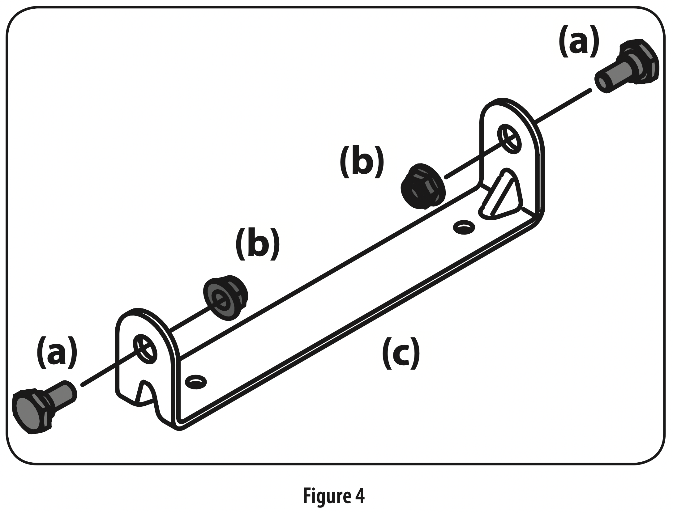
Remove the shoulder bolts (a) and lock nuts (b) from the seat mounting bracket (c) included in your hardware pack. See Figure 4.
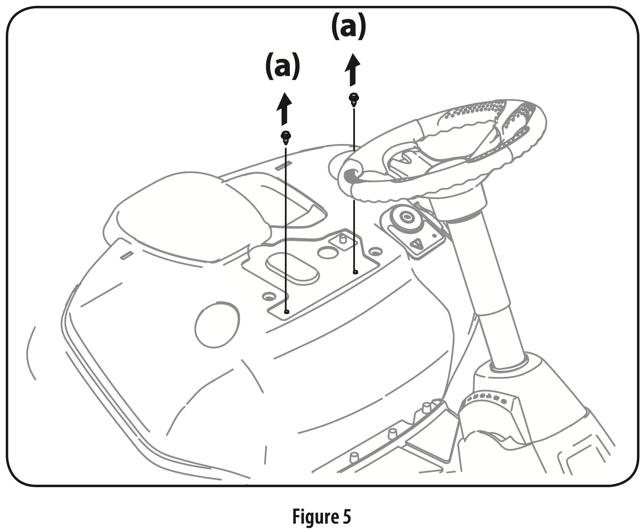
Remove the two self-tapping bolts (a) factory installed on the tractor. See Figure 5.
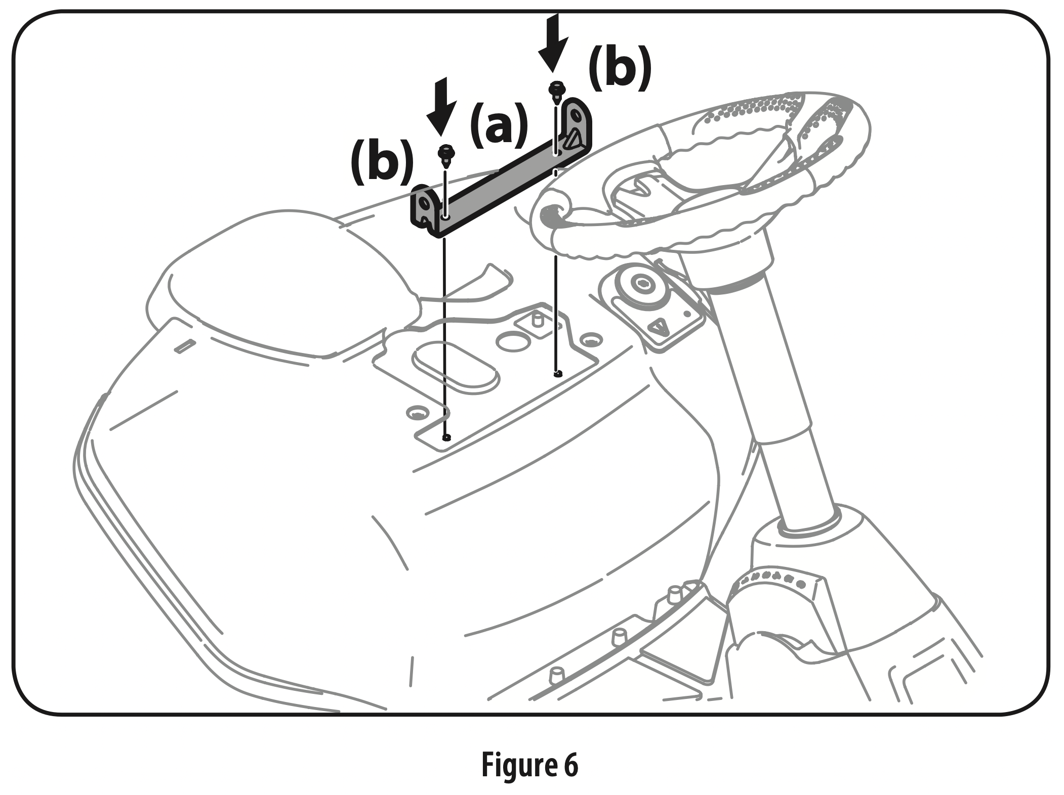
Align the seat bracket (a) in place over the holes from where the self-tapping bolts (b) were removed, as shown in Figure 6.
Using a 1/4” drive ratchet with a 3/8” socket, secure the seat bracket (a) with the self-tapping bolts (b) removed in step 2. See Figure 6. CAUTION: Do not use any type of power tool (e.g. impact gun or electric drill with nut driver attached) when tightening the self-tapping bolts to attach the seat bracket.
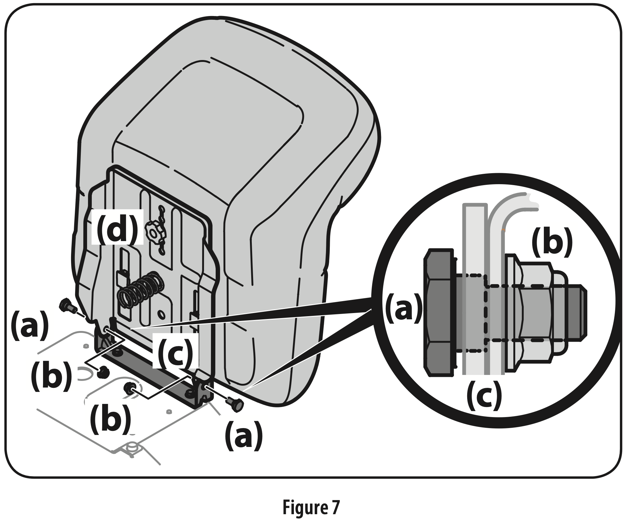
Position the seat assembly over the seat mounting bracket, aligning the holes provided. See Figure 7.
Install the two shoulder bolts (a) and lock nuts (b) removed from the seat mounting bracket (c) in Step 1. See Figure 7. Note: Make sure that the bolt’s shoulder is completely recessed into the seat bracket when securing the lock nut.
To adjust the position of the seat, loosen the adjustment knob (d) on the bottom of the seat. Slide the seat forward or backward as desired. Securely retighten the adjustment knob. Refer to Figure 7. Installing the Deck Chute WARNING: Never operate this tractor without either the mulch plug or deck chute installed.
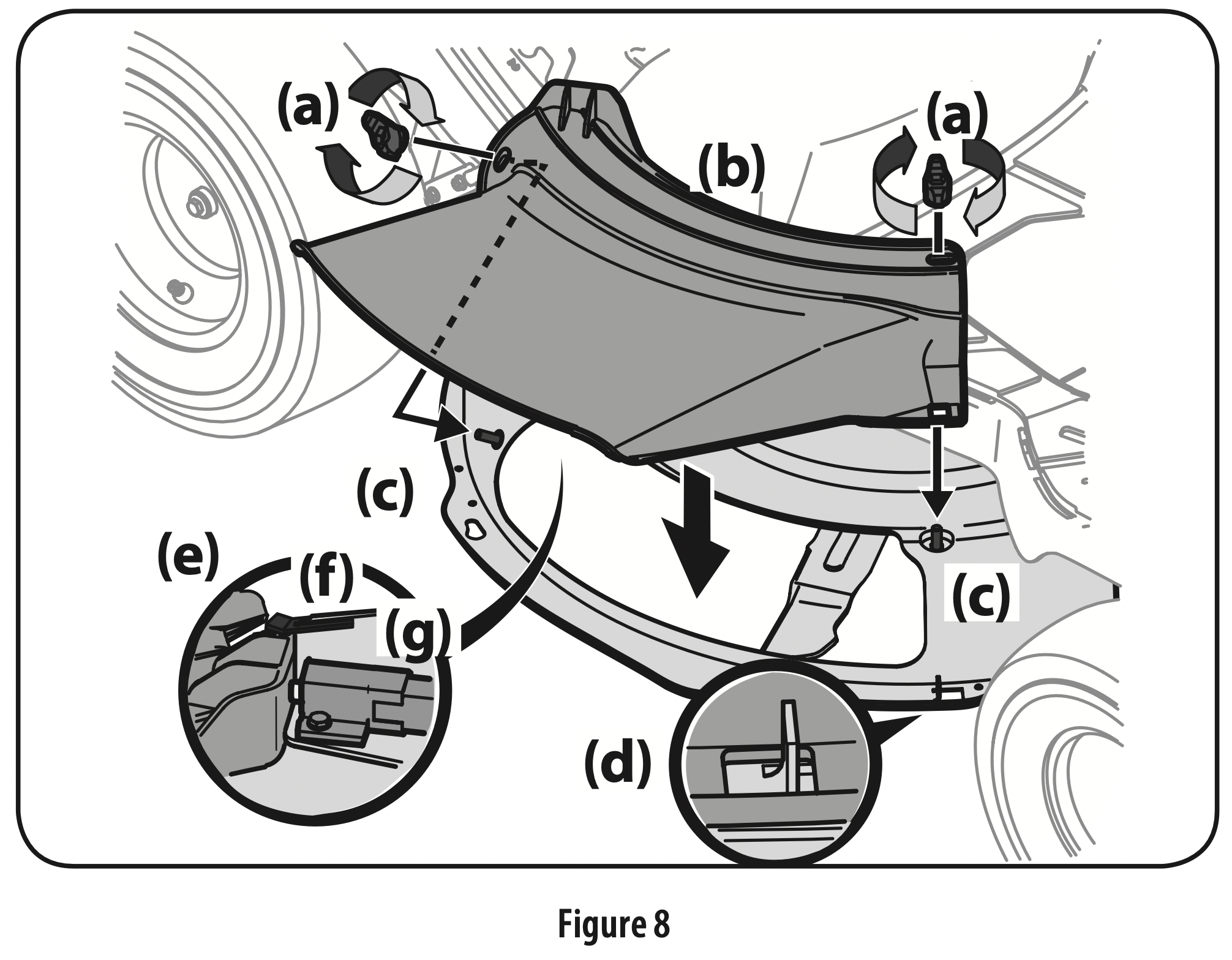
Remove the wing knobs (a) installed on the mowing deck and retain for later installation. See Figure 8.
Install the deck chute (b) into the deck discharge opening on the deck. The rear of the chute should be under the tab (f) on the rear deck bracket (g). The studs (c) on the deck surface will fit through the holes on the upper portion of the deck chute. The small tab (d) on the deck lip area will fit through the square cutout on the lower portion of the deck chute. See Figure 8. Important: Make certain that the upper-rear portion of deck chute (b) is depressing the safety switch (e) located on the deck surface and under the tab (f) on the rear deck bracket (g). The blade(s) will not start without the deck chute (b) properly in place.
Secure the deck chute (b) by tightening the wing knobs (a) removed in step 1. See Figure 8.
Installing the Mulch Plug (If equipped)
WARNING: Never operate this tractor without either the mulch plug or deck chute installed.
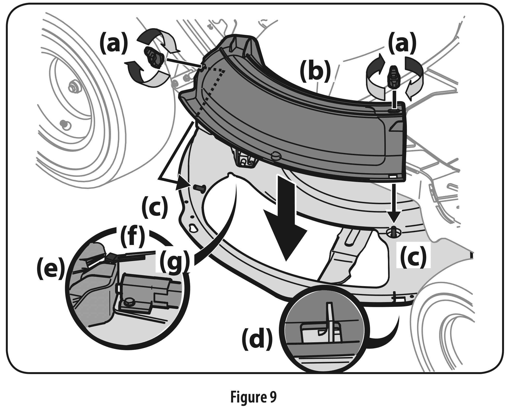
Remove the wing knobs (a) installed on the mowing deck and retain for later installation. See Figure 9.
Install the mulch plug (b) into the deck discharge opening on the deck. The rear of the mulch plug (b) should be under the tab (f) on the rear deck bracket (g). The studs (c) on the deck surface will fit through the holes on the upper portion of the mulch plug (b). The small tab (d) on the deck lip area will fit through the square cutout on the lower portion of the mulch plug (b). See Figure 9. Important: Make certain that the upper-rear portion of mulch plug (b) is depressing the safety switch (e) located on the deck surface and under the tab (f) on the rear deck bracket (g). The blade(s) will not start without the mulch plug (b) properly in place.
Secure the mulch plug (b) by tightening the wing knobs (a) removed in step 1.
Installing the Bumper (If equipped)
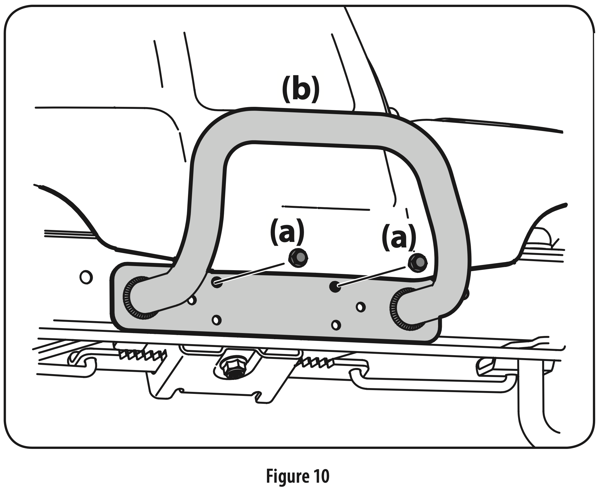
Remove the two screws (a) as shown in Figure 10.
Position the bumper (b) over the mounting holes and secure using the screws (a) removed in Step 1. See Figure 10.
Tire Pressure
WARNING: Equal tire pressure should be maintained at all times. Never exceed the maximum inflation pressure shown on the sidewall of the tire.
The recommended operating tire pressure is:
10 psi for the rear tires
14 psi for the front tires
Important: Refer to the tire sidewall for exact rating of the tire or maximum psi. Do not overinflate. Uneven tire pressure could cause the cutting deck to mow unevenly.
Charging the Batteries
WARNING: California Proposition 65
This product contains a chemical known to the State of California to cause cancer and reproductive harm. Wash hands after handling.
WARNING: The batteries contain corrosive fluid and toxic material — HANDLE WITH CARE. Keep away from children. Do not puncture, disassemble, mutilate, or incinerate. Explosive gases could be vented during charging or discharging. Charge in a well ventilated area, away from sources of ignition.
WARNING: Recharge only with the charger provided with this tractor. A charger that is not suitable for this machine may damage the batteries or create the risk of fire.
WARNING: Do not charge or operate the tractor in the rain or in wet conditions.
Rechargeable batteries degrade with time and use. The batteries may eventually need to be replaced. To have the batteries replaced, contact your authorized service dealer.
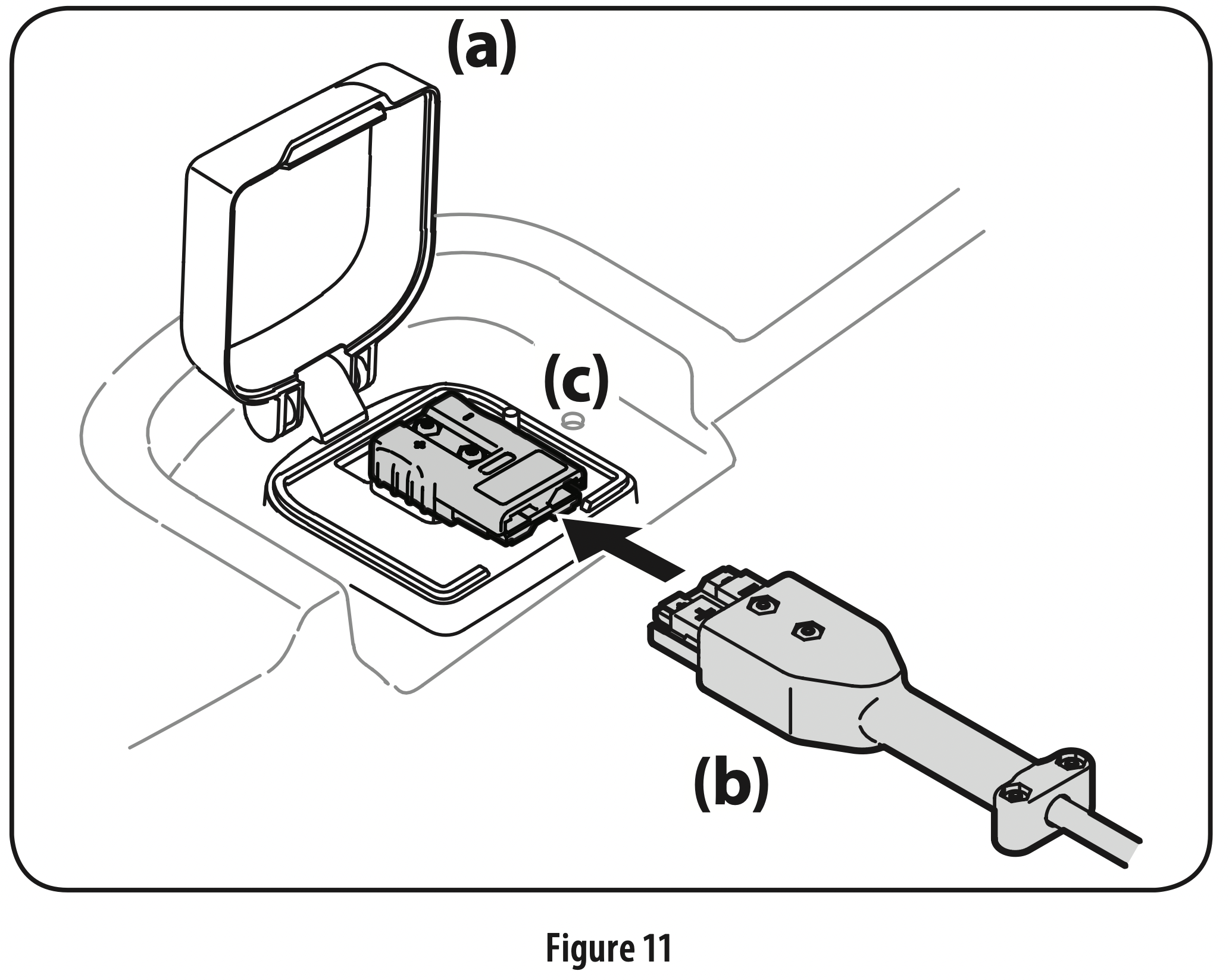
Lift the charge port door (a), located on the rear body panel of the tractor. See Figure 11.
Insert the charging cord (b) into the charge port (c). Plug charger cord (b) into wall outlet. See Figure 11. Note: It will take approximately 4 hours to fully charge the batteries. Note: The Vehicle Control Module (VCM) LED’s will blink continuously when charging and the LCD display will display percentage of charge. The battery is completely charged when all green lights are illuminated and the LCD displays 100%. Refer to the Operator’s Manual for more charging tips. Note: When the charging cord is plugged into the tractor and not yet plugged into the wall, the LED’s will illuminate continuously until the cord is plugged into the wall.
If at any time you get a charger fault when charging your battery, follow these procedures: a. Turn the power key off. b. Unplug the charger from the tractor. c. Unplug the charger from the power source. d. Plug the charger back into the power source. e. Plug the charger back into the tractor. f. It the problem persists contact qualified service personnel.
Battery Charging Tips
Use only the battery charger provided with this tractor.
The batteries should be fully charged before the initial use.
Never charge a frozen battery.
It is recommended that the tractor be charged once every month during off-season storage.
Always disconnect battery charger (or extension cord, if used) from the electrical outlet first, then disconnect battery charger from the charging port.
It is recommended that the batteries be fully charged after each use. Storing batteries in a discharged state could reduce future performance.
It will take approximately 4 hours to fully charge the batteries. Leaving the batteries connected to the charger for more than 4 hours will not damage the batteries.
The batteries do not develop a memory and do not need to be fully discharged before recharging.
OPERATION
Note: This Operator’s Manual covers several models. Tractor features may vary by model. Not all features in this manual are applicable to all tractor models and the tractor depicted may differ from yours.
Note: References to LEFT, RIGHT, FRONT, and REAR indicate that position on the tractor when facing forward while seated in the operator’s seat.
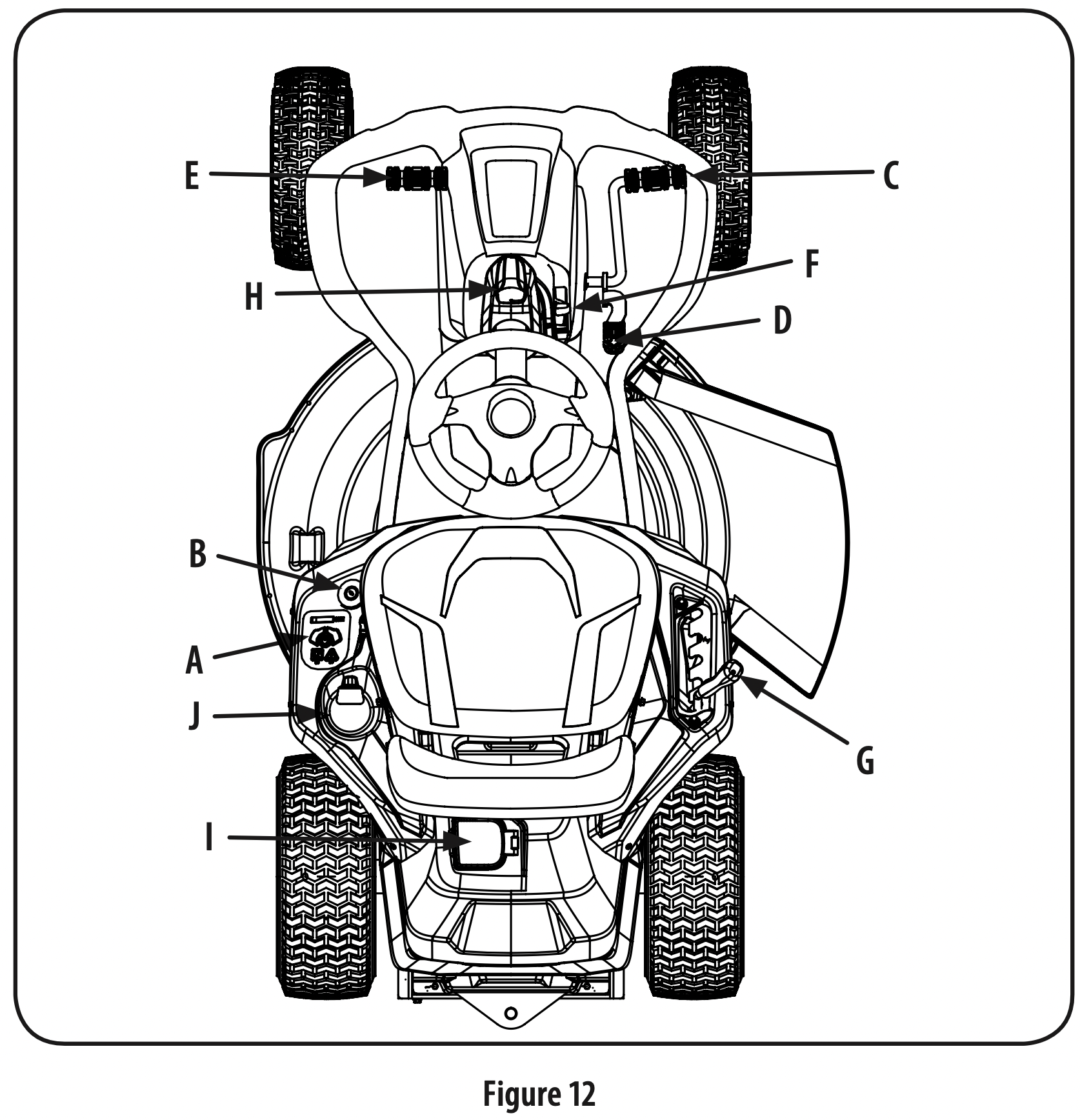
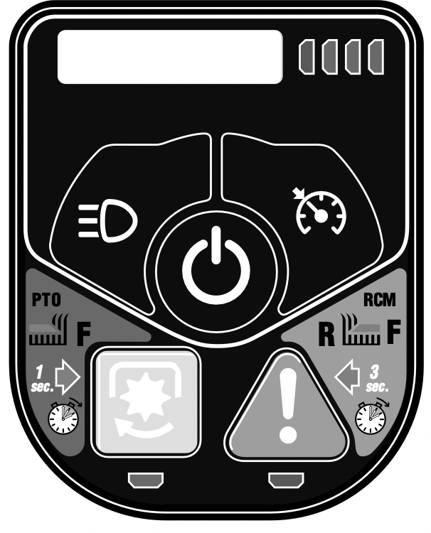
Vehicle Control Module (VCM) (A)
WARNING: Never leave a running machine unattended. Always disengage PTO, set parking brake, stop tractor and remove power key to prevent unintended starting.
The vehicle control module (VCM) is located on the left fender of the tractor seated in the operator’s position.
The VCM is the location of several control buttons for your tractor. The VCM inludes the START/STOP button, PTO (blades ON/OFF) button , Reverse Caution Mode (RCM) button, Headlight button, Cruise Control button, LCD Screen and the Battery Level Indicator.
CAUTION: Prior to operating the tractor, refer to both Safety Interlock Switches and Starting The Tractor in the Operation section of this manual for detailed instructions regarding the VCM and operating the tractor in REVERSE CAUTION MODE.
Start/Stop Button
Located on the VCM, the start/stop button is used to start and stop the tractor.
PTO (Blades ON/OFF) Button
Located on the VCM, the PTO button is used to engage the blades. To operate, press the PTO button for one second. The green indicator light below the PTO button is illuminated when there is power to the cutting deck and the LCD Screen displays “CUT DECK ON.” Pressing the PTO button again will disengage power to the cutting deck. The green indicator light is not illuminated when there is no power to the cutting deck.
Reverse Caution Mode (RCM) Button
CAUTION: Prior to operating the tractor, refer to the Operation section of this manual for detailed instructions regarding operating the tractor in REVERSE CAUTION MODE.
Located on the VCM, the RCM button allows the tractor to be operated in reverse with the blade(s) engaged. To activate the RCM, press the RCM button down for three seconds. When activated, the red indicator light is illuminated. To de-activate the RCM, press the RCM button again. When the RCM is not activated, the red indicator light is not illuminated. Refer to the Operation section of this manual for more information on operating the tractor in the reverse caution mode.
Note: Mowing in reverse is not recommended.
WARNING: Use extreme caution while operating the tractor in the REVERSE CAUTION MODE. Always look down and behind before and while backing. Do not operate the tractor when children or others are around. Stop the tractor immediately if someone enters the area.
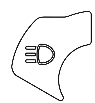
Headlight Button
Located on the VCM, the headlight button is used to turn the headlights on or off.
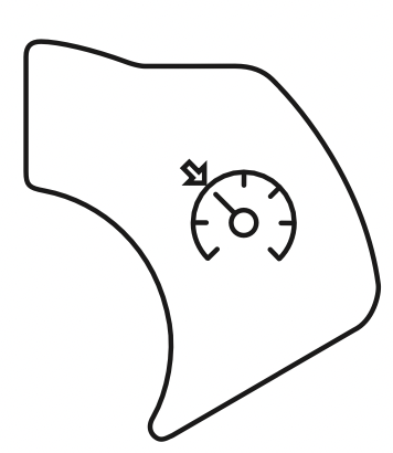
Cruise Control Button
Located on the VCM, pressing the cruise control button while the tractor is in motion allows the tractor to remain at a constant ground speed without applying pressure to the forward drive pedal, the LCD Screen displays “CRUISE ON” when the cruise control is activated. The cruise control can be disengaged by pressing either the cruise control button, the brake pedal or the drive pedal. Refer to the Operation section of this manual for detailed instructions regarding the cruise control feature.
Note: Cruise control will not engage at the tractor’s fastest ground speed. If the operator should attempt to do so, the tractor will automatically decelerate to the fastest optimal mowing ground speed.
Note: Cruise control will not engage in reverse.
Key Switch (B)
The key switch is located on the left fender and sends power to the VCM when the switch is in the ON (I) position. The tractor cannot be started unless the key switch is in the ON (I) position. Turning the switch to the OFF (O) position turns the tractor off and stops the flow of power to the VCM.
Note: Before your tractor can be started, the safety label covering the key switch must be removed. This label is in place to prevent unintended starting when the tractor is on display. Peel off the label to access the key switch.
Forward Drive Pedal (C)
The forward drive pedal is located on the right side of the steering column, along the running board. Press the forward drive pedal forward to cause the tractor to travel forward. Ground speed is also controlled with the forward drive pedal. The further forward the pedal is pressed, the faster the tractor will travel. The pedal will return to its original/neutral position when it is released.
Reverse Drive Pedal (D)
The reverse drive pedal is located on the right side of the steering column along the running board. Ground speed is also controlled with the reverse drive pedal. The further rearward the pedal is pressed, the faster the tractor will travel. The pedal will return to its original/neutral position when it is released.
Brake Pedal (E)
The brake pedal is located on the left side of the steering column, along the running board. Depress the pedal all the way down to engage the disc brake and bring the tractor to a complete stop.
Note: The brake pedal must be completely depressed to start the tractor. Refer to Safety Interlock Switches for more information.
Parking Brake Lever (F)
To set the parking brake, fully depress the brake pedal. Move the parking brake lever all the way back and into the parking brake position. Release the brake pedal to allow the parking brake to engage.
To release the parking brake, depress the brake pedal and move the parking brake lever forward and out of the parking brake position. Release the brake pedal.
Deck Lift Lever (G)
Located on your tractor’s right fender, the deck lift lever is used to change the height of the cutting deck (5 positions). To use, move the lever to the left, then place in the notch best suited for your application. The lowest position is “1” and the highest position is “5” Position “1” is approximately a 1” cutting height, Position “5” is approximately a 4” cutting height and the change in height is approximately 3/4” between each position.
Headlight (H)
The headlight is ON whenever the key switch is ON and the headlight button is pressed. To turn the headlight OFF, press the headlight button again.
Charging Port (I)
The charging port for the tractor is located on the rear of the tractor. To access the charging port, lift up on the charging port cover.
Cup Holder (J)
The cup holder is located to the left of the operator’s seat.
Operation
WARNING
Avoid Serious Injury or Death Know location and function of all controls.
Remove objects which could be thrown by the blade(s).
Go up and down slopes, not across.
Use extra caution on slopes. Do not mow or drive on slopes greater than 12°/21%. Avoid sudden turns. Use low speed.
Always engage the parking brake when turning the key switch off on an incline.
Do not operate machine where it could tip or slip.
If machine stops going uphill, stop blade(s) and back down slowly. Before leaving operator’s position, disengage blade(s), engage parking brake, shut off and remove key.
Be sure blade(s) and power are off before placing hands or feet near blade(s).
Keep safety devices (guards, shields, switches, etc.) in place and working.
Keep bystanders away.
Allow machine to cool before storing.
Keep machine free of debris.
Read Operator’s Manual
Safety Interlock Switches
This tractor is equipped with a safety interlock system for the protection of the operator. If the interlock system should ever malfunction, do not operate the tractor. Contact an authorized service dealer.
The safety interlock system prevents the tractor from operating the tractor unless the operator is in the seat with the brake pedal fully depressed or the parking brake set and the drive pedal in the NEUTRAL position..
The tractor will not operate with the charger cord plugged into the charging port and/or the charging port cover open or removed.
The tractor will not operate unless the discharge chute, mulch plug or bagger chute is in place and properly installed.
The tractor will automatically shut off the blade(s) and drive motors if the operator leaves the seat.
Note: To restart the tractor, follow the proper starting procedures.
WARNING: Do not operate the tractor if the safety interlock system is malfunctioning. This system was designed for your safety and protection.
Engaging the Parking Brake
Fully depress the brake pedal and hold it down with your foot.
Move the parking brake lever back into the parking brake position.
Release the brake pedal to allow the parking brake to engage.
Releasing the Parking Brake
Depress the brake pedal and move the parking brake lever forward out of the parking brake position.
Setting the Cutting Height
Select the height position of the cutting deck by placing the deck lift lever in any of the five (5) different cutting height notches on the right side of the fender.
WARNING: Keep hands and feet away from the discharge opening of the cutting deck.
Refer to Leveling the Deck in the Service & Maintenance section of this manual for more detailed instructions regarding deck adjustment.
Starting the Tractor
WARNING: Do not operate the tractor if the interlock system is malfunctioning. This system was designed for your safety and protection.
Unplug the charging cord (if necessary). If the cord is still plugged in a reminder will display on the VCM when the key switch is turned on.
Sit in the operator’s seat. A reminder will display on the VCM if the operator is not in the seat when the key switch is turned on.
Insert the power key into the key switch.
Fully depress the brake pedal or set the parking brake. If the brake is not engaged a reminder will display on the VCM when the key switch is turned on.
Turn the power key clockwise to the ON (I)position.
Press the start/stop button down for two seconds (two beeps).
Stopping the Tractor
WARNING: If you strike a foreign object, stop the tractor, turn the power key to OFF and remove. Thoroughly inspect the machine for any damage. Repair the damage before restarting and operating.
If the blade is engaged, press the PTO button to disengage the PTO.
Press the start/stop button for one second (one beep) or turn the power key counter-clockwise to the OFF (O) position.
Remove the key from the key switch to prevent unintended starting.
Driving the Tractor
WARNING: Avoid sudden starts, excessive speed and sudden stops.
WARNING: Do not leave the seat of the tractor without first pressing the PTO button to turn off the blade(s), depressing the brake pedal and engaging the parking brake. If leaving the tractor unattended, also turn the power key to the OFF position and remove the power key.
WARNING: Always look down and behind before and while backing up to avoid a back-over accident.
To travel FORWARD, slowly press the forward drive pedal to travel FORWARD until the desired speed is reached.
To travel in REVERSE, slowly press the reverse drive pedal until the desired speed is reached.
The tractor is brought to a stop by releasing the forward or reverse drive pedal and/or depressing the brake pedal.
WARNING: Before leaving the operator’s position for any reason, disengage the blade(s), engage the parking brake, turn the key switch to OFF position and remove the power key.
Reverse Caution Mode (RCM)
The REVERSE CAUTION MODE button allows the tractor to be operated in reverse with the blade(s) (PTO) engaged.
Note: Mowing in reverse is not recommended.
WARNING: Use extreme caution while operating the tractor in the REVERSE CAUTION MODE. Always look down and behind before and while backing. Do not operate the tractor when children or others are around. Stop the tractor immediately if someone enters the area.
To use the REVERSE CAUTION MODE:
Note: The operator MUST be seated in the tractor seat.
Start the tractor as previously instructed.
Press and hold the RCM button down for three seconds until the red indicator light illuminates. The red indicator will remain on as long as the REVERSE CAUTION MODE is on.
Once activated (indicator light ON), the tractor can be driven in reverse with the cutting blade(s) (PTO) engaged.
Always look down and behind before and while backing to make sure no children are around. After resuming forward motion, press the RCM button to return to normal mowing operation.
The REVERSE CAUTION MODE will remain activate until:
The RCM button is pressed or
The operator leaves the seat.
Driving on Slopes
WARNING: Refer to the SLOPE GAUGE in the Important Safe Operation Practices section to help determine slopes where you may operate the tractor safely.
Mow up and down slopes, NEVER across.
Exercise extreme caution when changing direction on slopes.
Watch for holes, ruts, bumps, rocks, or other hidden objects. Uneven terrain could overturn the tractor. Tall grass can hide obstacles.
Avoid turns when driving on a slope. If a turn must be made, turn down the slope. Turning up a slope increases the chance of a roll-over.
Avoid stopping when driving up a slope. If it is necessary to stop while driving up a slope, start up slowly and carefully to reduce the possibility of flipping the tractor over backward.
Engaging the PTO
Engaging the PTO transfers power to the cutting deck. To engage the blade(s), proceed as follows:
Press the PTO button for one second. When activated the green indicator light under the PTO button is illuminated.
Mulching (If equipped)
Mulching is a process of recirculating grass clippings repeatedly beneath the cutting deck. The ultra-fine clippings are then forced back into the lawn where they act as a natural fertilizer. Refer to the Assembly & Set-up section of this manual for instructions on how to install the mulch kit (if equipped).
Using the Deck Lift Lever
To raise the cutting deck, move the deck lift lever to the left, then place it in the notch best suited for your application. Refer to Setting the Cutting Height in this section.
Mowing
WARNING: To help avoid blade contact or a thrown object injury, keep bystanders, helpers, children and pets at least 75 feet from the machine while it is in operation. Stop machine if anyone enters the area.
WARNING: Plan your mowing pattern to avoid discharge of materials toward roads, sidewalks, bystanders and the like. Also, avoid discharging material against a wall or obstruction which may cause discharged material to ricochet back toward the operator.
The following information will be helpful when using the cutting deck with your tractor:
Do not mow or drive at high ground speed, especially if a mulch kit or grass collector is installed.
For best results it is recommended that the first two laps be cut clockwise with the discharge facing towards the center of your lawn. After the first two laps, reverse the direction to discharge to the outside for the balance of cutting. This will give a better appearance to the lawn.
Do not cut the grass too short. Short grass invites weed growth and yellows quickly in dry weather.
Under heavier conditions it may be necessary to go back over the cut area a second time to get a clean cut.
Do NOT attempt to mow heavy brush and weeds and extremely tall grass. Your tractor is designed to mow lawns, NOT clear brush.
Keep the blade sharp and replace the blade when worn. Refer to Cutting Blade in the Service section of this manual for proper blade sharpening instructions.
SERVICE AND MAINTENANCE
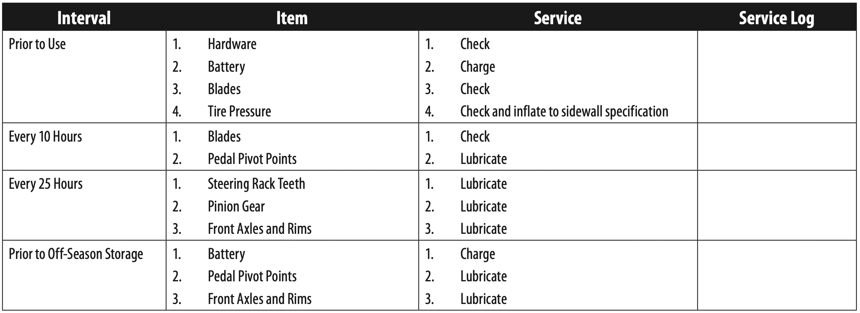
MAINTENANCE SCHEDULE
WARNING: Before inspecting, cleaning or servicing the machine, power off the tractor and remove the key from the key switch.
† Clean more often under dusty conditions or when airborne debris is present.
Note: This Operator’s Manual covers several models. Tractor features may vary by model. Not all features in this manual are applicable to all tractor models and the tractor depicted may differ from yours.
DANGER: The electrical components on this tractor are not serviceable. Please contact an authorized service dealer for any service needs.
DANGER: Have your tractor serviced by qualified service personnel using only identical replacement parts. This will ensure that the safety of the tractor is maintained.
Post-Operation Tractor Care
After each operation of the tractor, the following procedures should be implemented to extend the life of your tractor and ensure safe operating conditions.
DANGER: Failure to follow these recommendations may result in serious injury to yourself or others and may cause damage to the tractor.
Cleaning the Underside of the Deck
WARNING: To prevent serious injury, do not use water to clean the tractor, battery or battery charger. Do not use strong detergents. Household cleaners that contain aromatic oils such as pine and lemon, and solvents such as kerosene, can damage plastic.
The underside of tractor deck should be cleaned after each use as grass clippings, leaves, dirt and other debris will accumulate. This accumulation of grass clippings, etc., is undesirable as it will promote rust and corrosion.
Remove any buildup of grass and leaves on or around the motor (DO NOT USE WATER). Wipe the tractor clean with a dry cloth.
If debris is allowed to build up on the underside of the machine, tilt the tractor forward or on its side and clean with a suitable tool.
Important: Do not use a pressure washer or garden hose to clean your tractor. These may cause damage to electric components or the electric motor. The use of water will result in shortened life and reduce serviceability.
Cleaning the Tractor
WARNING: If the tractor has been recently run, metal surfaces will be hot and can cause burns to the skin. Let the tractor cool for at least five minutes. Exercise caution to avoid burns.
Your tractor should be cleaned after each use and under certain conditions, i.e. dry conditions and/or mulching situations, additional cleaning may be necessary.
One of the best ways to keep your tractor running efficiently and to reduce fire risk is to regularly remove debris buildup from the tractor. Follow the recommendations below and contact your authorized dealer with any questions.
Allow the machine to cool in an open area before cleaning.
Do not use water on any part of the tractor. Doing so can cause damage to the tractor’s electrical components and motor. The use of compressed air and/or leaf blower or a brush, damp sponge or rag will help keep the tractor clean.
Clean around fuses, all wiring and harnesses, etc.
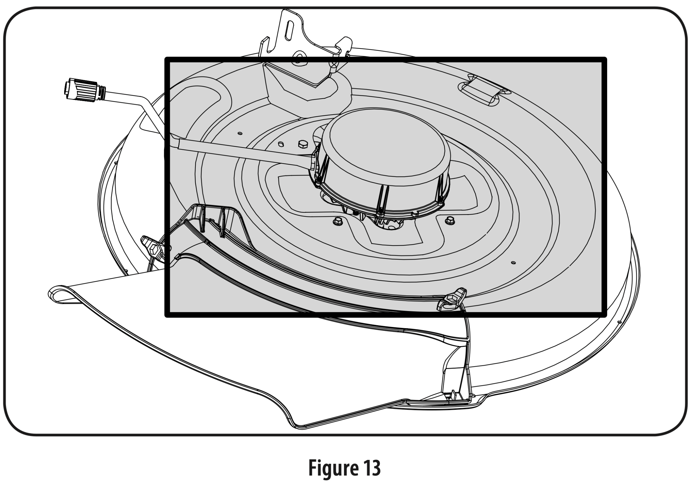
Clean the top of the tractor deck. See Figure 13.
Clean around and near the transmission, axle and the fan area. See Figure 14.
Debris can accumulate anywhere on the tractor, especially on horizontal surfaces. Additional cleaning may be necessary when mowing in dry conditions or when mulching.
Excess lubrication can become collection sites for debris. Immediate repair and cleaning up excess lubrication can help reduce fire hazards.
In addition to cleaning the tractor before operating and storing, do not attempt to mow unusually tall grass (10” or higher), dry grass (e.g., pasture) or piles of dry leaves. Dry grass or leaves may build up on the tractor deck presenting a potential fire hazard.
Storing the Tractor
Allow the machine to cool in an open area before storing.
Do not park the tractor near any flammable materials (wood, cloth or chemicals) or any open flames or other potential source of ignition (furnace, water heater or any other type of heater).
Remove all combustible materials from the tractor before storing. Empty cargo boxes, grass catchers or containers.
Fully charge the batteries and recharge the batteries every 30 days when in storage.
Removing The Tractor From Storage
Fully charge the batteries and inflate the tires to the recommended pressures.
Drive the tractor without a load to make certain all the tractor systems are functioning properly.
Maintenance
WARNING: Before performing any maintenance or repairs,disengage blade(s) PTO, set parking brake, turn key switch to OFF position and remove power key to prevent unintended starting.
Lubrication
Pivot Points & Linkage: Lubricate all the pivot points on the drive system, parking brake and lift linkage at least once a season with light oil.
Rear Wheels: The rear wheels should be removed from the axles once a season. Lubricate the axles and the rims well with an all-purpose grease before re-installing them.
Front Axles: Clean around and near the transmission, axle and the fan area. See Figure 14.
Each end of the tractor’s front pivot bar may be equipped with a grease fitting. Lubricate with a grease gun after every 25 hours of tractor operation.
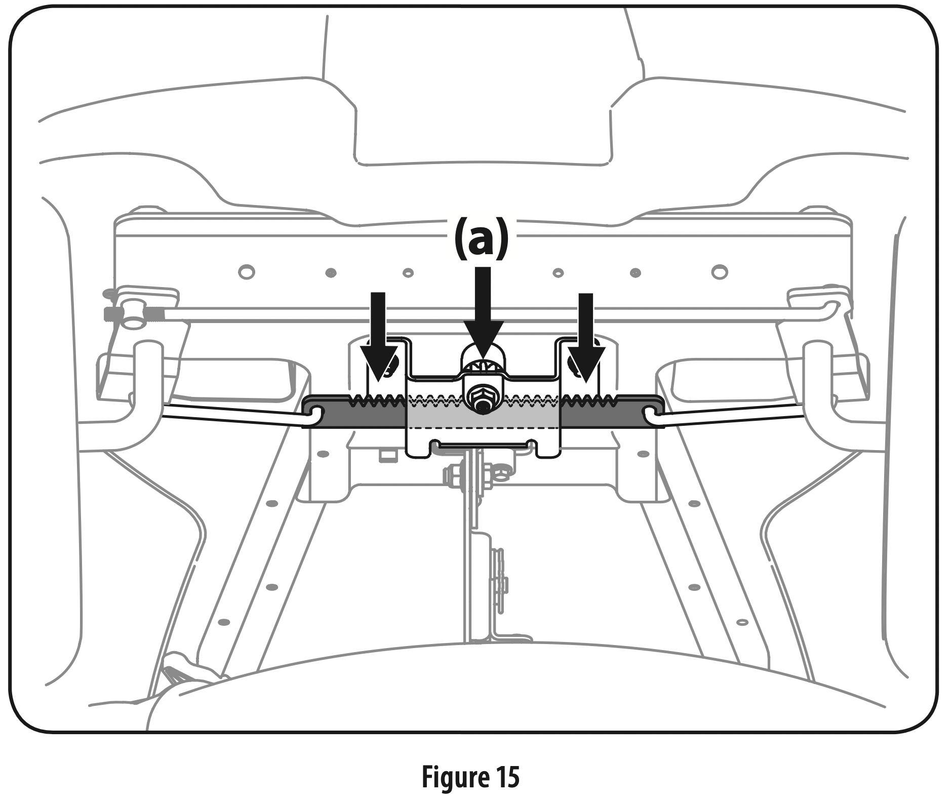
Lubricate Rack & Pinion: Once per season, or every 25 hours of operation, it will be necessary to lubricate the steering rack teeth and pinion gear (a) located under the front of the tractor. Using standard automotive grease, apply grease to the front side of the steering rack teeth and pinion gear (a), as indicated in Figure 15.
Battery Storage
The batteries should be stored with a full charge. Discharged batteries can freeze faster than charged batteries in cold temperatures.
The batteries should be fully charged once every month. Note: It will take approximately 4 hours to fully charge the batteries. Leaving the batteries connected to the charger for more than 4 hours will not damage the batteries, but when the charging is complete the charger should be disconnected.
Batteries should not be kept in a discharged state. Permanent damage to the batteries can occur.
Fully recharge the batteries before returning to service.
Charging the Batteries
WARNING: The batteries contain corrosive fluid and toxic material — HANDLE WITH CARE. Keep away from children. Do not puncture, disassemble, mutilate, or incinerate. Explosive gases could be vented during charging or discharging. Charge in a well ventilated area, away from sources of ignition.
WARNING: Recharge only with the charger provided with this tractor. A charger that is not suitable for this machine may damage the batteries or create the risk of fire.
WARNING: Do not charge or operate the tractor in the rain or in wet conditions.
Note: Rechargeable batteries degrade with time and use. The batteries may eventually need to be replaced. To have the batteries replaced, contact your authorized Service Dealer.
Note: Replace batteries if battery capacity drops below 50% of initial capacity
Note: Using old or faulty batteries could cause a system fault that results in loss of power
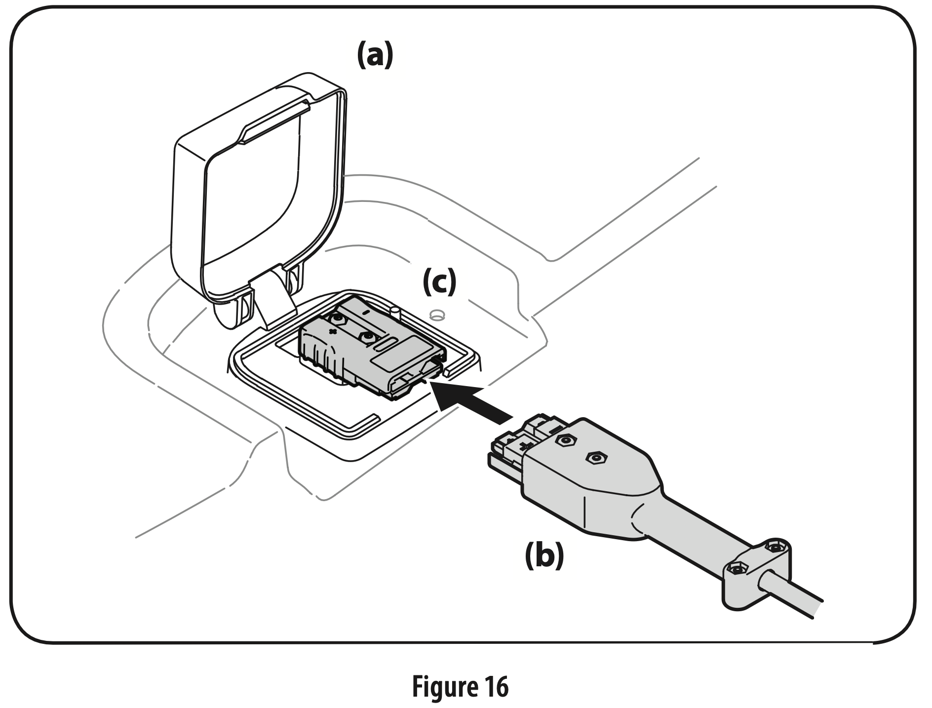
Lift the charge port door (a), located on the rear body panel of the tractor.
Insert the charging cord (b) into the charge port (c). Plug charger cord (b) into wall outlet. See Figure 16. Note: It will take approximately 4 hours to fully charge the batteries. Note: The Vehicle Control Module (VCM) LED’s will blink continuously when charging and the LCD display will display percentage of charge. The battery is completely charged when all green lights are illuminated and the LCD displays 100%. Refer to the Operator’s Manual for more charging tips. Note: When the charging cord is plugged into the tractor and not yet plugged into the wall, the LED’s will illuminate continuously until the cord is plugged into the wall.
If at any time you get a charger fault when charging your battery, follow these procedures: Turn the power key off. Unplug the charger from the tractor. Unplug the charger from the power source. Plug the charger back into the power source. Plug the charger back into the tractor. It the problem persists contact qualified service personnel.
Battery Charging Tips
Use only the battery charger provided with this tractor.
The batteries should be fully charged before the initial use.
Never charge a frozen battery.
It is recommended that the tractor be charged once every month during off-season storage.
Always disconnect battery charger (or extension cord, if used) from the electrical outlet first, then disconnect battery charger from the charging port.
It is recommended that the batteries be fully charged after each use. Storing batteries in a discharged state could reduce future performance.
It will take approximately 4 hours to fully charge the batteries. Leaving the batteries connected to the charger for more than 4 hours will not damage the batteries.
The batteries do not develop a memory and do not need to be fully discharged before recharging.
Fuses
CAUTION: For continued protection against risk of injury or electric shock, do not replace blown fuses please call qualified service personnel.
Adjustments
WARNING: Never attempt to make any adjustments while the key switch is ON, except where specified in the Operator’s Manual.
Seat
Refer to the Set-Up & Assembly section of this manual for seat adjustment instructions.
Parking Brake
WARNING: Never attempt to adjust the brakes while the tractor is running. Always disengage blade(s) PTO, set parking brake, turn key switch to OFF position and remove power key to prevent unintended starting.
If the tractor does not come to a complete stop when the brake pedal is completely depressed, or if the tractor’s rear wheels can roll with the parking brake applied, the brake is in need of adjustment. See an authorized service dealer to have your brakes properly adjusted.
Deck
Note: Check the tractor’s tire pressure before performing any deck leveling adjustments. Refer to Tires in the Assembly section for more information regarding tire pressure.
Front-to-Rear Levelling
It is possible to adjust the pitch of the cutting deck. The front of the deck should be between 0” (level) and 1/4” lower than the rear of the deck. Adjust if necessary as follows:
With the tractor parked on a firm, level surface, place the deck lift lever in the middle position and rotate the blade so that it is aligned with the front and rear of the tractor.
Measure the distance from the front of the blade tip to the ground and the rear of the blade tip to the ground. The first measurement taken should be between 0” (level) and 1/4” less than the second measurement. Determine the approximate distance necessary for proper adjustment and proceed, if necessary, to the next step.
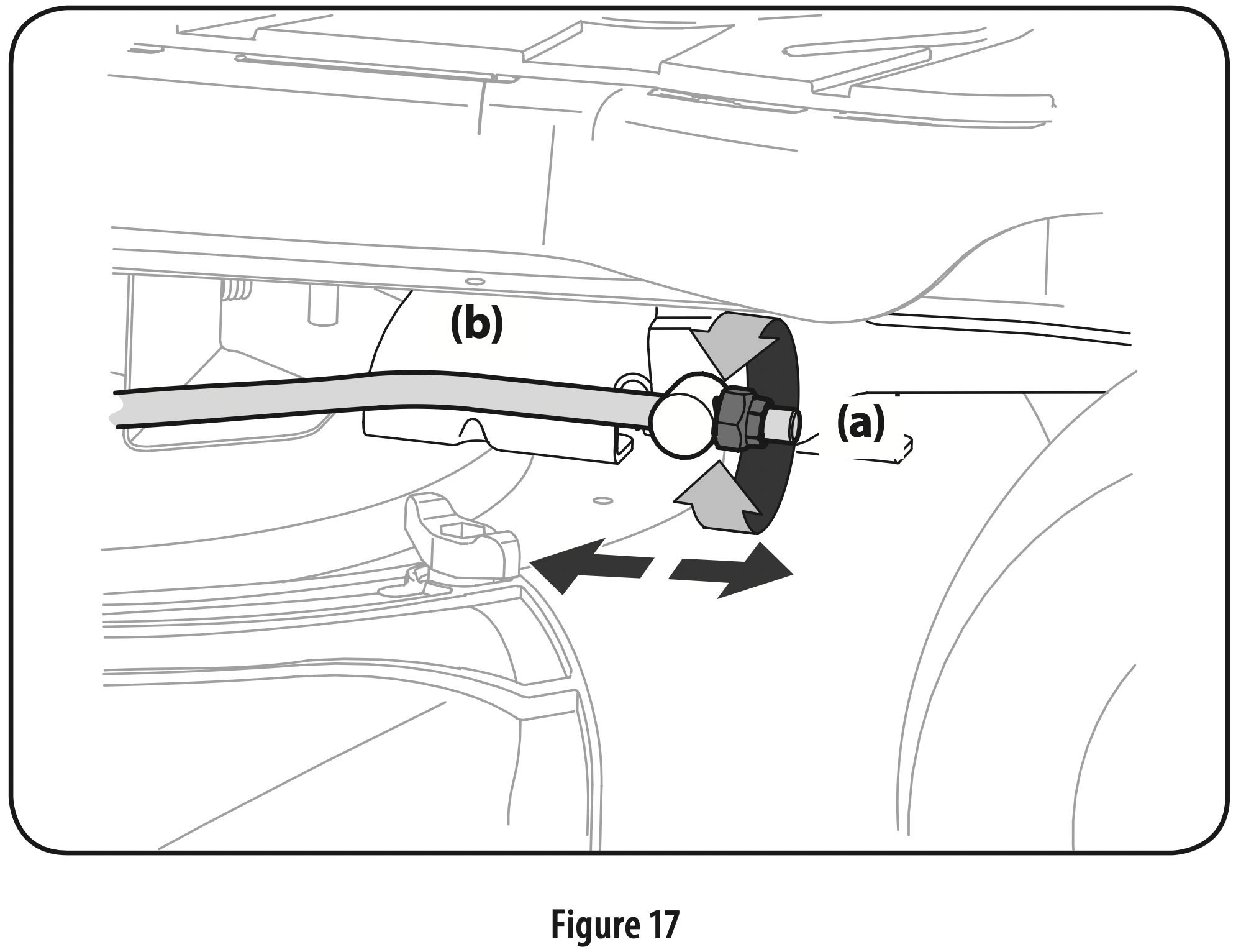
Locate the flange lock nut (a) on the front end of the PTO lift rod (b). See Figure 17. a. Tighten the fla nge lock nut (a) to raise the front of the deck. b. Loosen the flange lock nut (a) to lower the front of the deck.
Tires
Refer to the Assembly & Set-Up section for more information regarding tire pressure.
Service
Cutting Deck Removal
To remove the cutting deck, proceed as follows:
Remove power key and engage the parking brake.
Lower the deck by moving the deck lift lever into the lowest (#1) position on the right fender.
Remove the bow-tie cotter pin (a) and flat washer (b) from the deck lift assembly, and retain for reinstallation later. See Figure 18.
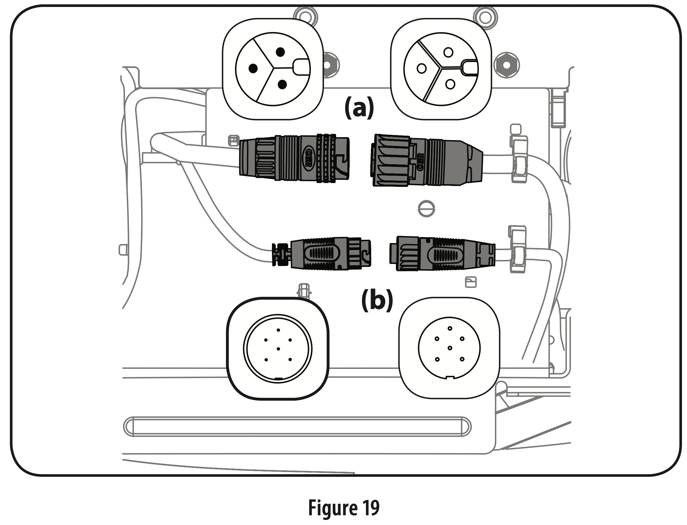
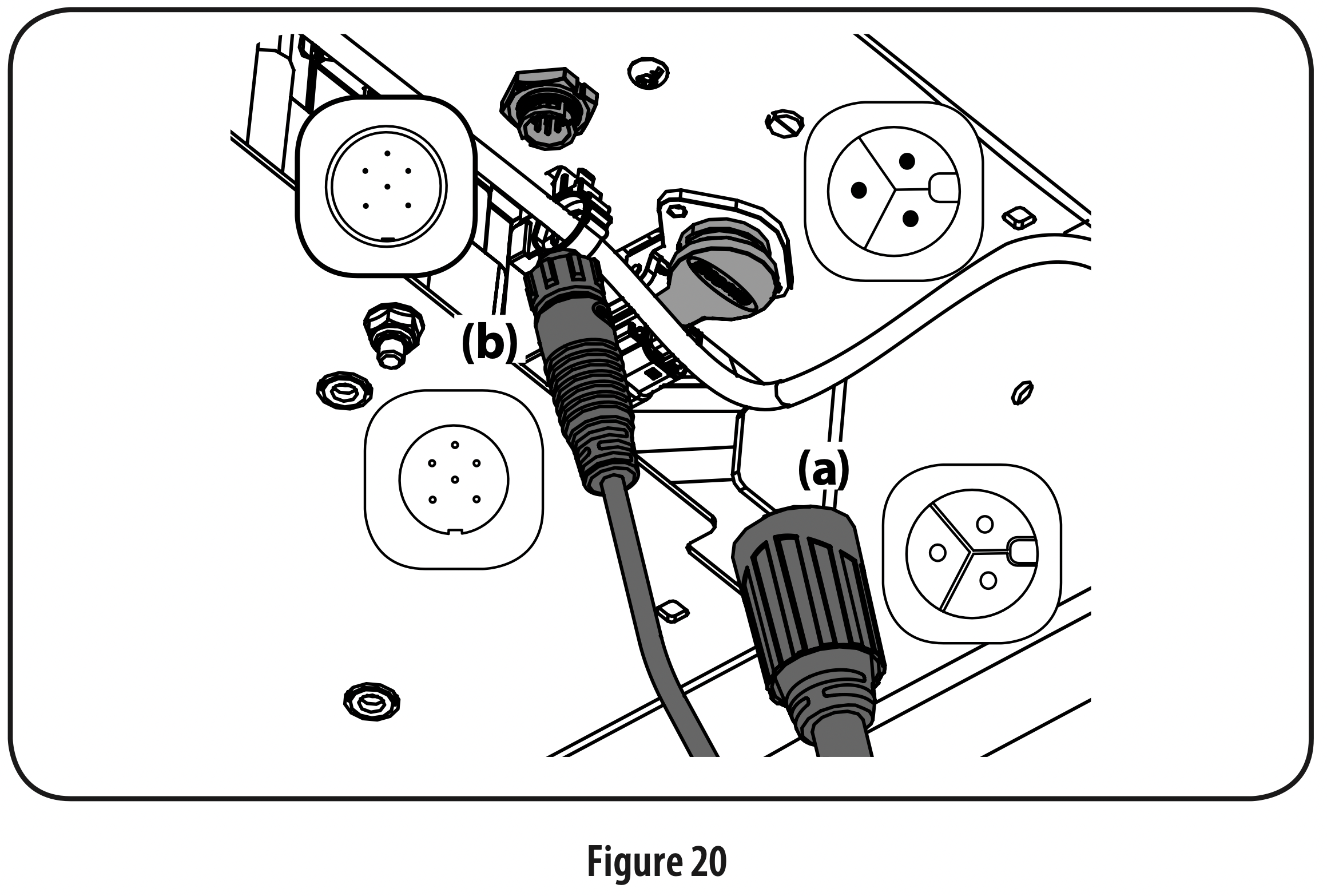
Disconnect the deck motor(s) from the adapters on the underside of the tractor. Rotate the collar on the larger connector (a) counterclockwise and carefully pull apart. Repeat the procedure with the smaller connector (b). Note: Your mower may have one of two different deck motor connector setups. If your mower has horizontally positioned connectors, see Figure 19. If your mower has vertically positioned connectors, see Figure 20. Note: Always disconnect the larger connector first.
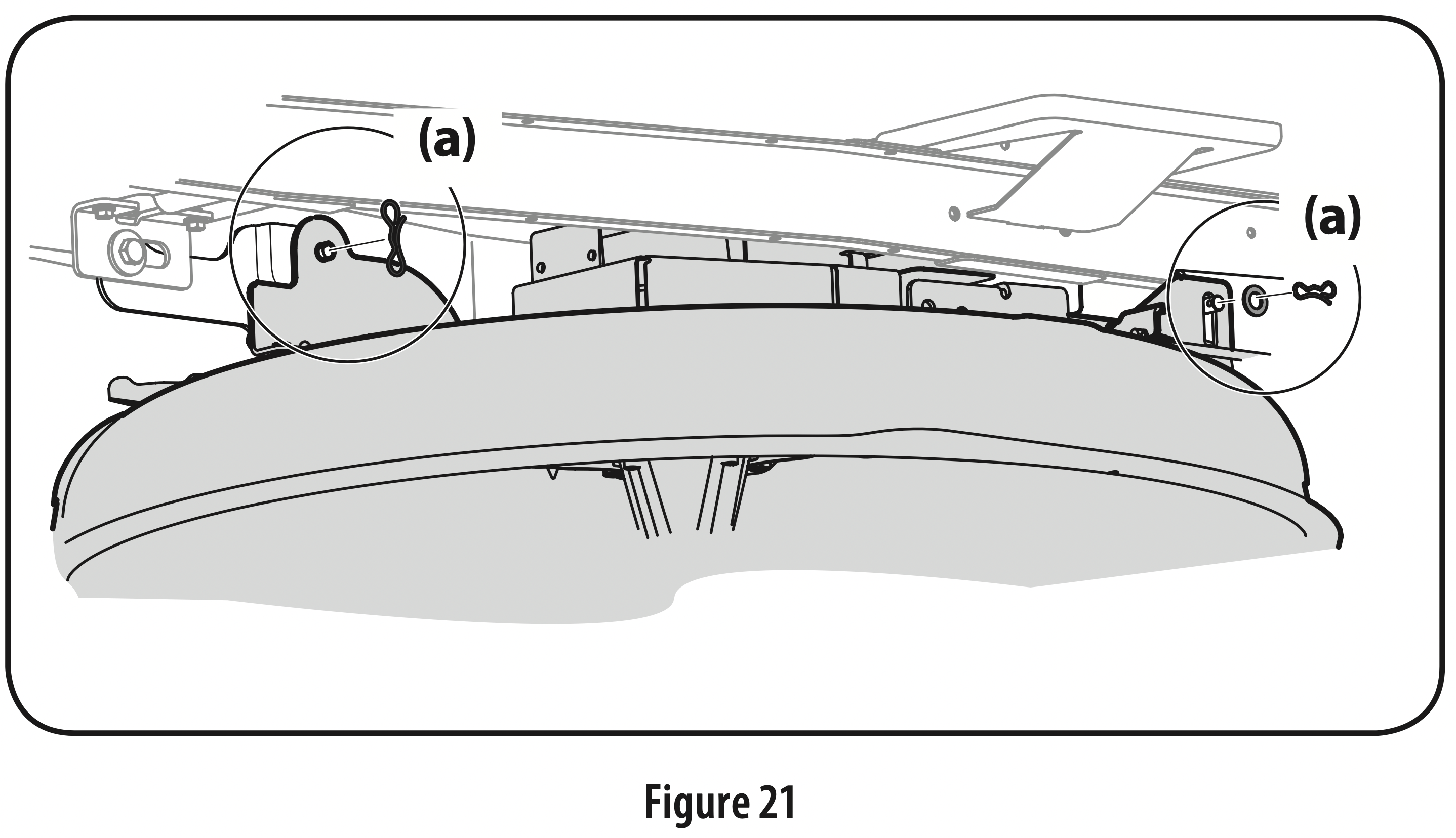
Remove the remaining bow-tie cotter pins (a) securing the deck to the tractor, as shown in Figure 21.
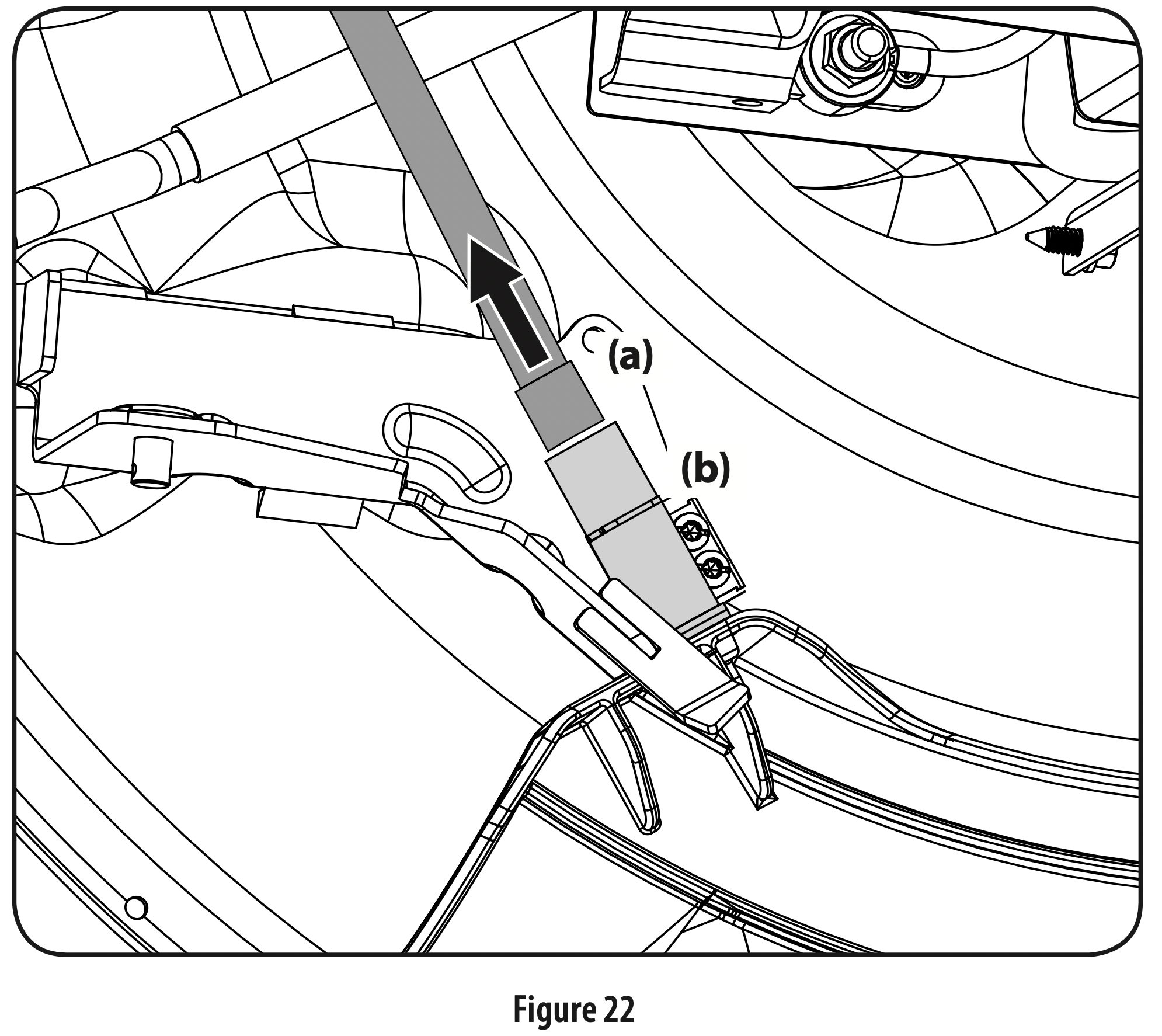
Unplug the wire connector (a) from the safety switch (b) at the rear of the chute opening. See Figure 22.
Move the deck lift lever into the highest (#5) position on the right fender to raise the deck lift arms up and out of the way.
Gently slide the cutting deck (from the left side) out from underneath the tractor.
Cutting Deck Installation
Raise the deck lift lever into the highest (#5) position on the right fender to move the deck lift arms out of the way.
Gently slide the cutting deck (from the left side) back under the tractor.
Plug the wire connector (a) into the safety switch (b) at the rear of the chute opening. See Figure 22. Note: Be sure to securely reconnect the wire connector to the safety switch in Figure 22, you tractor will not start or operate without the safety switch properly connected.
Lower the deck lift lever to the lowest (#1) position.
Secure the deck to the deck lift arms using two bow-tie cotter pins. See Figure 21. Note: The bow-tie cotter pins (a) should be installed from the top down.
Reconnect the deck motors on the underside of the tractor. Always connect the larger connector first and then the smaller connector. See Figure 19. Note: When reconnecting the deck motors, you must be sure that the connections are secure.
Blade(s)
WARNING: Shut the tractor off, engage parking brake and remove power key before removing the cutting blade(s) for sharpening or replacement. Protect your hands by using heavy gloves when grasping the blade.
WARNING: Periodically inspect the blade(s) and/or spindle for cracks or damage, especially after you’ve struck a foreign object. Do not operate the machine until damaged components are replaced.
CAUTION: If the cutting edge of the blade(s) has previously been sharpened, or if any metal separation is present, replace the blade(s).
The blade(s) may be removed as follows.
Note: It may be easier to change the blade(s) by first removing the deck from beneath the tractor, (refer to Cutting Deck Removal earlier in this section) then gently flip the deck over to expose its underside. It is possible to change the blade(s), however, with the deck still attached to the tractor. If attempting to change the blade(s) with the deck still installed on the tractor, first move the deck lift lever to its highest (#5) position.
Remove the mulch plug, deck chute or bagging chute, if equipped, exposing the deck chute opening.
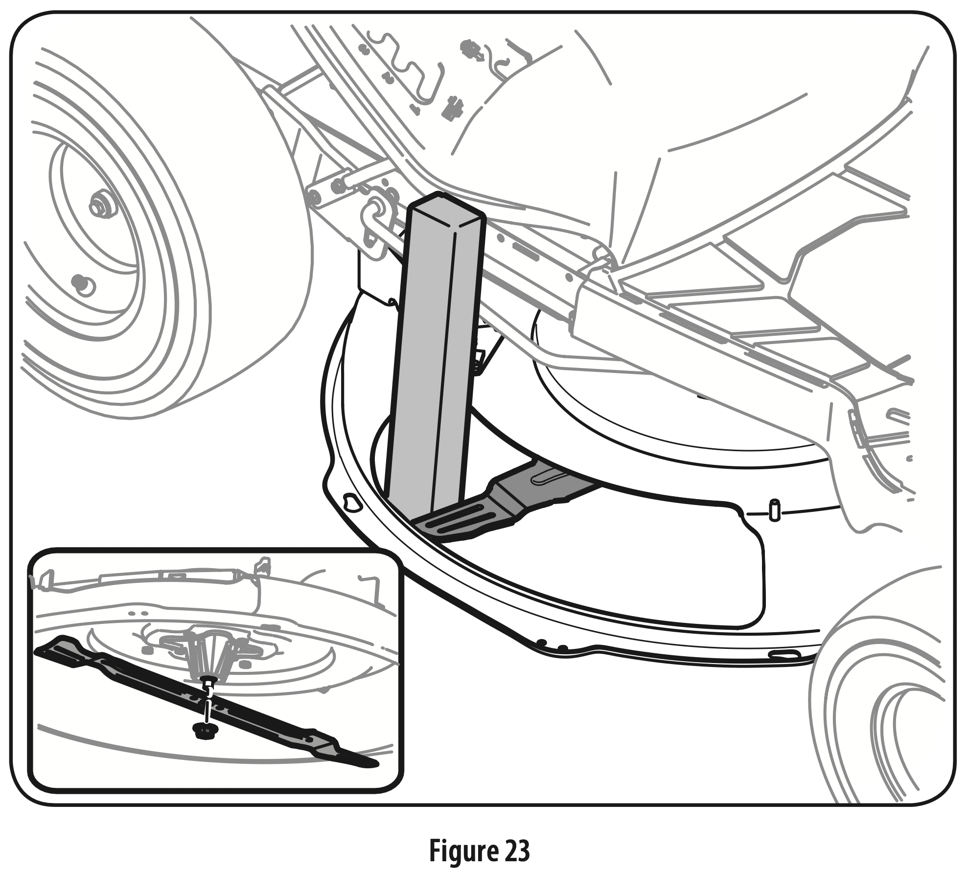
Using a block of wood or 2 x 4, insert it into the deck opening and rotate the blade around until it wedges the wood between the deck opening and the cutting blade, as shown in Figure 23.
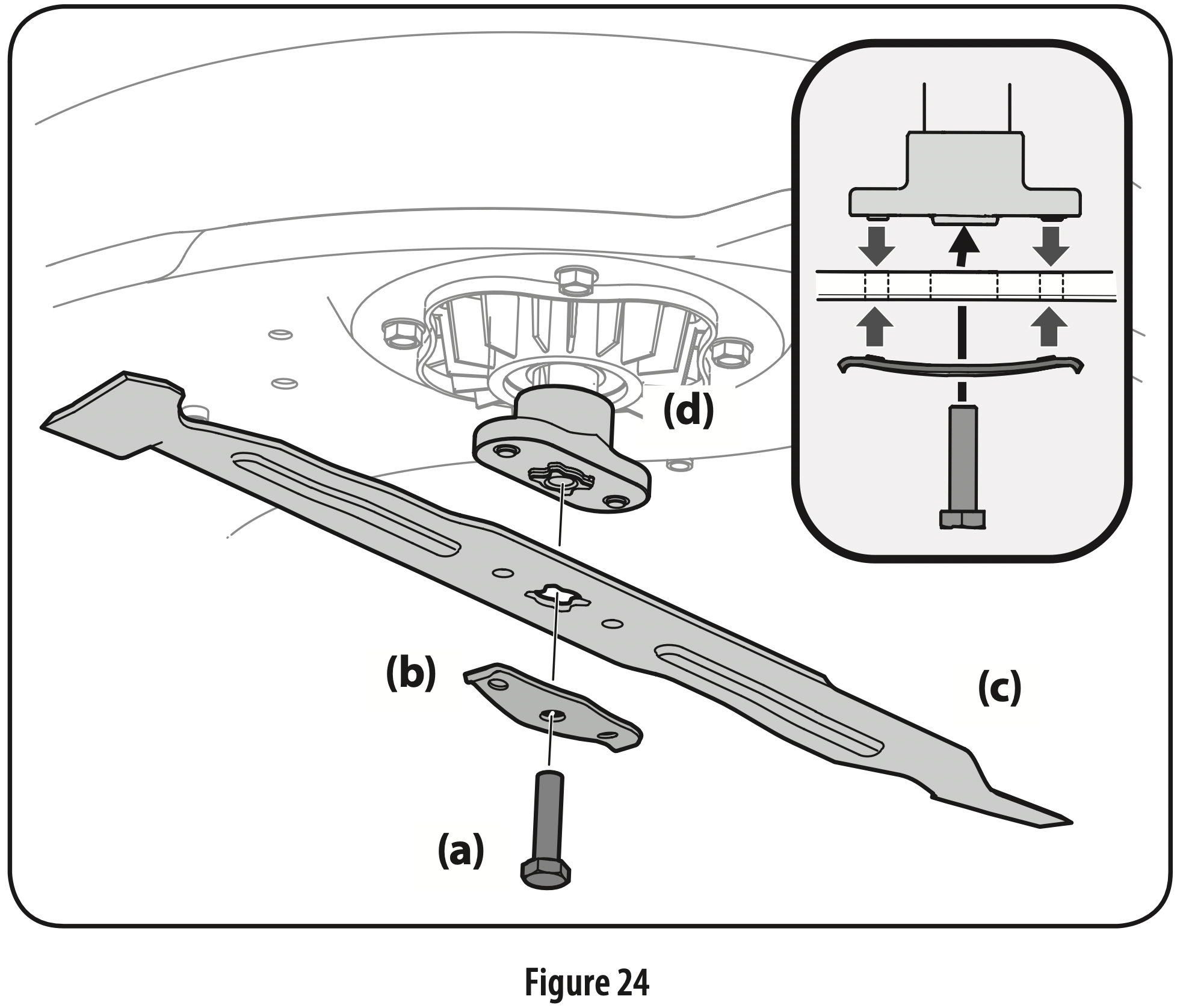
Remove the hex screw (a) and the blade bell support (b) which holds the blade (c) and the blade adapter (d) to the deck motor. See Figure 24.
Remove blade (c) and adapter (d) from the deck motor spindle See Figure 24.
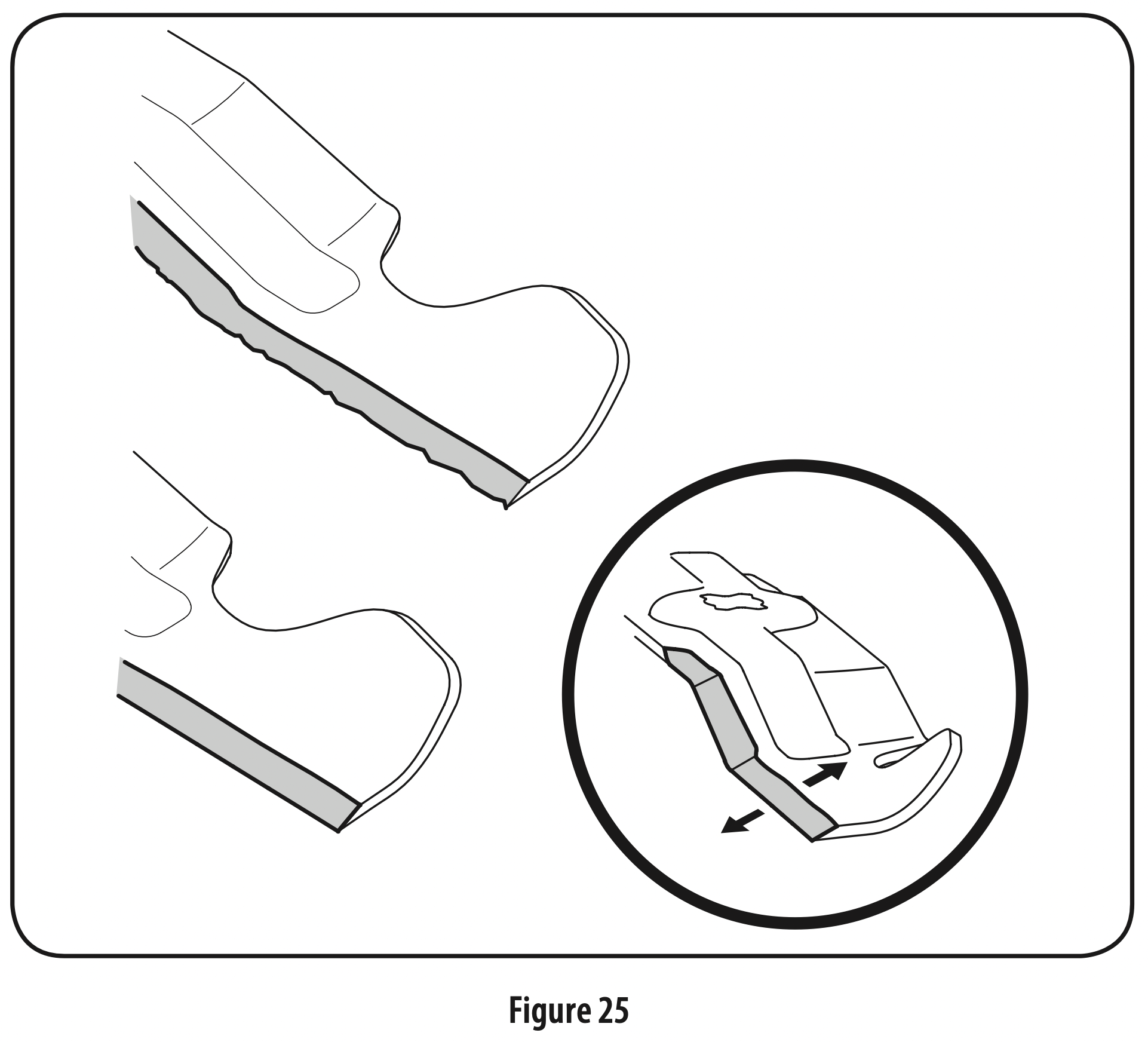
To properly sharpen the cutting blade, remove equal amounts of metal from both ends of the blade along the cutting edges, parallel to the trailing edge, at a 25°- to 30° angle. Always grind each cutting blade edge equally to maintain proper blade balance. See Figure 25.
Test the blade’s balance using a blade balancer. Grind metal from the heavy side until it balances evenly.
WARNING: A poorly balanced blade will cause excessive vibration, may damage the tractor and/or result in personal injury.
Note: When replacing the blade, be sure to install the blade with the side of the blade marked ‘‘Bottom’’ (or with a part number stamped in it) facing the ground when the tractor is in the operating position.
CAUTION: Use a torque wrench to tighten the hex bolt to between 450-600 in-lbs.
Battery Disposal
Disposing of Damaged or Worn-Out Batteries
WARNING: The following toxic and corrosive material is used in this battery: LITHIUM-ION, a toxic material.
WARNING: To prevent contamination of the environment, contact your local waste disposal agency for specific instructions before disposing of damaged or worn-out lithium-ion batteries. Take batteries to a local recycling and/or disposal center, certified for lithium-ion battery disposal.
WARNING: Do not use broken or cracked batteries, even if there is no leakage. Replace damaged or worn-out batteries with new batteries. DO NOT ATTEMPT TO REPAIR BATTERIES! Repair attempts may result in severe personal injury, due to explosion or electrical shock.
To avoid personal injury and damage to the environment:
Do not attempt to remove or destroy any of the battery components. Do not open or mutilate the battery. If a leak develops, released electrolytes are corrosive and toxic. Do not get the solution in your eyes or on your skin, and do not swallow it.
Do not dispose of the battery in the regular household trash.
Do not dispose of the battery in a fire. The cell may explode.
Do not dispose of the battery where it will become part of any waste landfill or municipal solid waste stream.
Cover the battery terminals with heavy-duty adhesive tape.
Dispose of the battery according to local, state and federal regulations.
Dispose of the battery promptly.
Troubleshooting
Excessive Vibration
1. Blade loose or unbalanced
Tighten cutting blade and deck spindle
2. Cutting blade damaged, unbalanced or bent.
Replace the blade
Uneven Cut
1. Deck not properly leveled
Perform front-to-rear deck adjustment
2. Cutting blade dull or damaged
Sharpen or replace cutting blade
3. Uneven tire pressure
Check and correct tire pressure in all four tires
Tractor will not mulch grass
1. Wet grass
Do not mulch when grass is wet
2. Excessively high grass
Mow once at a high cutting height, then mow again at desired height or make a narrower cutting swath
3. Dull blade
Sharpen or replace blade
Tractor stopped or will not start
1. Electrical system fault
Shut off and restart tractor
If problem persists, contact an authorized service dealer
The blades do not rotate /blades stopped
1. Overload
Allow deck motor(s) to cool/raise deck height
2. Low battery
Return home, plug into charger
The blade(s) stopped when traveling in reverse
1. Blade(s) stopped
Restart blade(s) (PTO)
Make sure Reverse Caution Mode is activated
Reduced Speed
1. Low battery
Charge battery as instructed in the battery charger manual
2. Overload
Raise deck
LCD Screen Messages
Brake Switch Fault: The deck and drive shut off. Power off and restart tractor. If problem persists contact qualified service personnel.
Accelerator Pedal Sensor Fault: The deck and drive shut off. Power off and restart tractor. If problem persists contact qualified service personnel.
Seat Switch Fault: The deck and drive shut off. Power off tractor, sit in seat and restart tractor. If problem persists contact qualified service personnel.
Cutting Deck Overload: The deck and drive shut off. Power off the tractor, clean under the deck as instructed in the Post-Operation Tractor Care section and restart the tractor. Raise the deck and/or cut at a slower pace. If problem persists contact qualified service personnel.
Drive Motor Over Current Fault: The deck and drive shut off. Power off, let the tractor cool and restart tractor. If problem persists contact qualified service personnel.
Drive Motor Control Fault: The deck and drive shut off. Power off and restart tractor. If problem persists contact qualified service personnel.
Self Test Fault: The deck and drive shut off. Power off and restart tractor. If problem persists contact qualified service personnel.
Electrical Faults: The deck and drive shut off. Power off and restart tractor. If problem persists contact qualified service personnel.
Battery Temperature Low: Move the tractor to a warm location and allow the battery to warm. If problem persists contact qualified service personnel.
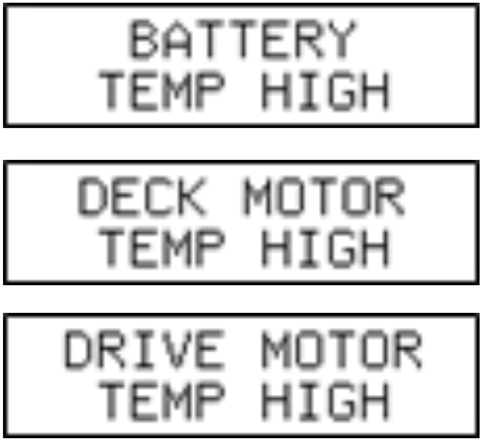
High Temperature Faults: Power off, let the tractor cool and restart tractor. If problem persists contact qualified service personnel.
Charge Port Door is Open: The tractor will come to a stop and shut off. Close the charge port door and restart tractor. If problem persists contact qualified service personnel.
Low Battery Warning: The battery is low and should be charged as soon as possible.
Sharpen Blade Warning: When this warning is displayed, the blades should be checked and sharpened.
Check Tire Pressure Warning: When this warning is displayed check and adjust the tire pressure.
Recommendation would be twice a season season. You should clean the underside of the deck on occasion. It does not need to be cleaned any more than if this were a standard riding mower.
#4 Does this Craftsman E150 need to be plugged in when not in use or just when charging it?
The mower is to be plugged in while charging.
#5 Could this mower be stored under a carport instead of garage or shed?
It can be stored under a carport but we suggest covering it.
To install the mulch plug: 1. Remove the wing knobs installed on the mowing deck and retain for later installation. 2. Install the mulch plug into the deck discharge opening on the deck. The rear of the mulch plug should be under the tab on the rear deck bracket. The studs on the deck surface will fit through the holes on the upper portion of the mulch plug. The small tab on the deck lip area will fit through the square cutout on the lower portion of the mulch plug. Important: Make certain that the upper-rear portion of mulch plug is depressing the safety switch located on the deck surface and under the tab on the rear deck bracket. The blade will not start without the mulch plug properly in place. 3. Secure the mulch plug by tightening the wing knobs removed in step 1.
Recommended for Terrain Type = Flat with obstacles
#8 How well does this mower go up mild slopes in a yard?
All of our residential wheeled power equipment is designed and approved to safely operate on slopes up to a maximum of 15 degrees of incline. A mower will safely handle slopes when starting at the bottom of the slope and mowing side-to side, rather than up and down. When turning to go back the other way, we recommend turning uphill by keeping the uphill lever generally fixed while using the downhill lever to execute the turn.