OPERATOR’S MANUAL Zero-Turn Tractor Lapbar Drive Control Levers
Operation
Note: This Operator’s Manual covers several models. Tractor features may vary by model. Not all features in this manual are applicable to all tractor models and the tractor depicted may differ from yours.
Note: References to LEFT, RIGHT, FRONT, and REAR indicate that position on the tractor when facing forward while seated in the operator’s seat.
1 Lapbar Drive Control Levers
The RH (Right Hand) and LH (Left Hand) lapbar drive control levers are located on each side of the
operator’s seat. The hinged levers pivot outward to permit the operator to sit in the seat, or dismount. To start the tractors engine, the lapbar drive control levers must be fully out and in park position. When the lapbar drive control levers are fully outward, the parking brake is engaged.
2 Deck Height Index
If equipped with a deck lift handle:
Each height index notch corresponds to approximately a 1⁄2” (12.7mm) change in deck height. See 3 in Figure 15.
If equipped with a deck lift pedal and knob:
Each rotation represents a ⁄” (6.35 mm) change in deck height. Positions range from 1” (2.5 cm) to 4-1⁄2 ”
(11.4 cm) at the highest point. See 4a and 4b in Figure 15.
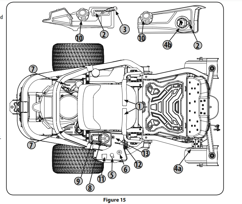
3 Deck Lift Handle (If Equipped)
The deck lift handle is used to raise and lower the mower deck. To lower the deck, pull the deck lift handle to the right out of the index notch and push downward. To raise the deck, pull upward. Ensure handle is fully positioned into the height index notch when the desired height is attained.
4a Deck Lift Pedal (If Equipped)
The deck lift pedal is located on the front, right corner of the platform. The pedal is used in conjunction with the deck lift knob (if equipped) to raise and lower the mowing deck. Push forward on the deck lift pedal, rotate the deck lift knob to the desired height and release the deck lift pedal.
4b Deck Lift Knob (If Equipped)
The deck lift knob is used in conjunction with the deck lift pedal (if equipped) to raise and lower the mowing deck. Push forward on the deck lift pedal, rotate the deck lift knob to the desired height and release the deck lift pedal.
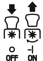
5 Power Take-Off (PTO)
Electric PTO (If equipped)
The PTO switch operates the electric PTO clutch mounted on the bottom of the engine crankshaft. Pull the switch knob upward to engage the PTO clutch, or push the knob downward to disengage the clutch. The PTO switch must be in the “OFF” position when starting the engine.
6 Ignition Switch

The ignition switch has three positions:
STOP  — The engine and electrical system is turned off.
RUN  — The riding mower electrical system is energized.
START  — The starter motor will turn over the engine. Release the key immediately when the engine starts.
Note: To prevent accidental starting and/or battery discharge, remove key from the ignition switch when tractor is not in use.
7 Transmission Bypass Rods
The transmission bypass rods (one for each RH and LH transmission) are located on the rear of the tractor, next to the engine.When engaged, the two rods open a bypass within the hydrostatic transmissions, which allows the tractor to be pushed short distances by hand. Refer to the Assembly section for additional instructions.

8 Cup Holder
The cup holder is located on the top of the console.
9 Storage Tray
The storage tray is located to the rear of the console.
10 Fuel Tank Cap
Turn the fill cap at least two clicks counter clockwise and pull upward to remove. The fuel cap is tethered to the tractor to prevent its loss. Do not attempt to remove the cap from the tractor. Fill tank to ½ ” (12.7 mm)below the bottom of the filler neck, allowing some space in the tank for fuel expansion. Do not overfill the tank.
Push the cap downward on the fuel tank fill neck and turn at least two clicks clockwise to tighten. Always re-install the fuel cap tightly onto the fuel tank after removing.

11 Hour Meter & LCD Service Minder (If equipped)
The LCD service minder will remind the operator of maintenance intervals for changing the engine oil, air filter service, low engine and low battery warnings. When the key is rotated out of the STOP position but is not in the START position, the LCD service minder & hour meter will briefly display the battery voltage, followed by the tractor’s accumulated hours.
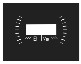
Note: When the ignition key is out of the STOP position the hourglass  symbol is illuminated/blinks to indicate it is recording the hours of tractor operation, regardless of whether the engine has been started.
Change Oil
The LCD screen will alternate the letters “CHG”, followed by “OIL”, followed by “SOON”, followed by the meter’s accumulated time. “CHG/OIL/SOON/TIME” will alternate on the display for 7 minutes after the meter reaches 50 hours. This oil service minder interval will occur every 50 hours. Before the interval expires, change the engine oil as instructed in the Engine Operator’s Manual
Low Oil
Note: The low oil pressure function only works if the engine is equipped with an oil pressure switch.
The LCD screen will alternate the letters “LO” followed by “OIL”, followed by the meter’s accumulated time, which indicates the engine has low oil pressure. This is common when starting an engine. The indicator will remain active until the engine sufficiently builds pressure after starting. If it remains on with the engine at full speed and after a few minutes of operation, stop the tractor immediately and check the engine oil level and add as instructed in the Engine Operator’s Manual. If the oil level is correct and the indicator persists, contact an authorized service dealer.
Low Battery
At startup, the battery voltage will briefly display, then changes to accumulated hours. The letters “LO” followed by the letters “BATT” will display, followed by the meter’s accumulated time. “LO/BATT/TIME” is displayed on the LCD when the voltage drops below 11.5 volts. When this occurs, the battery is in need of a charge or the engine’s charging system is not generating sufficient amperage. Charge the battery as instructed in the Product Care section of this manual or have the charging system checked by your local service dealer.
Air Filter Service
The LCD screen will display the letters “CLN” followed by the letters “AIR”, followed by “FILT”, followed by the meter’s accumulated time. “CLN/AIR/FILT/TIME” will alternate on the display for 7 minutes after the meter reaches 25 hours. This air filter service minder time interval will be every 25 hours. On intervals that are common with oil service, the oil message will be displayed first followed by the air filter message.
12 Throttle/Choke Control Lever or Throttle Control Lever
Note: When set in a given position, a uniform engine speed will be maintained.
Throttle Control Lever (If equipped)
Push the throttle control lever forward to increase the engine speed. The tractor is designed to operate with the throttle control lever at full throttle (FAST) when the tractor is being driven and the tractor deck is engaged. Pull the throttle control lever rearward to decrease the engine speed.

Throttle/Choke Control Lever (If equipped) Push the throttle/choke control lever forward to increase the engine speed. The tractor is designed to operate with the throttle/choke control lever at full throttle (FAST) when the tractor is being driven and the mower deck is engaged. Pull the throttle/choke control lever rearward to decrease the engine speed. When starting the engine, push the control lever fully forward into the “CHOKE” position. After starting and warming the engine, move the control handle rearward until you feel it move past the choke detent. Throttle is not meant to control unit speed, throttle should remain in high speed while operating blades.

13 Choke Control (If equipped)
The choke control determines the position of the engine choke. Pull the knob out to choke the engine; push the knob in to open the choke.

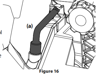
Multi-Tool (If equipped)
The multi-tool (a) is located on the front of the right console. The multi-tool (a) can be used as a deck lift lockout, to remove the footpan bolt, adjust the height of the lapbar drive control levers, drive control lever stop adjustment and can be used as a removal tool with the ½ ” socket end. See the Product Care section for more information on multi-tool (a) usage. See Figure 16.
Headlights (Not shown/If equipped)
The headlights are located on the front of the frame. The headlights are ON whenever the ignition key is rotated out of the STOP position and OFF when the ignition key is moved to the STOP position.
Seat Adjustment Lever (Not shown/If equipped)
The seat adjustment lever is located under the seat. The seat adjustment lever allows for adjustment forward or backward of the operator’s seat. Refer to the Assembly & Set-Up section for instructions on adjusting the seat position.
Note: If your tractor is not equipped with a seat adjustment lever, it can be adjusted using the knobs on the underside of the seat. Refer to the Assembly & Set-Up section for instruction on adjusting the seat.
Operation
Before Operating Your Tractor
• Before operation, refer to Maintenance Schedule chart located in this manual for regularly scheduled service items.
• This engine is certified to operate only on clean, fresh, unleaded gasoline. Fill only with clean, fresh, unleaded gasoline with a pump sticker octane rating of 87 or higher.
• Do not use gasoline left over from the previous season, to minimize gum deposits in the fuel system.
• Gasohol (up to 10% ethyl alcohol, 90% unleaded gasoline by volume) is an approved fuel. Other gasoline/alcohol blends are not approved.
• Methyl Tertiary Butyl Ether (MTBE) and unleaded gasoline blends (up to a maximum of 15% MTBE by volume) are approved fuels. Other gasoline/ether blends are not approved.
Safety Interlock System

This tractor is equipped with a safety interlock system for the protection of the operator. If the interlock system should ever malfunction, do not operate the tractor. Contact an authorized service dealer.
• The safety interlock system prevents the engine from cranking or starting unless the parking brake is engaged, and the PTO lever is in the DISENGAGED (OFF) position.
• The engine will automatically shut OFF if the operator leaves the seat before engaging the parking brake.
• The engine will automatically shut OFF if the operator leaves the tractor’s seat with the PTO switch in the ENGAGED (ON) position, regardless of whether the parking brake is engaged.
Checking the Safety Interlock Circuits
Periodically check the safety interlock circuits to ensure they are working properly. If a safety circuit is not working as designed, contact you Service dealer to have the tractor inspected. DO NOT operate the tractor if any safety circuit is not functioning properly. To check the safety circuits, proceed as follows:
1. Pull the PTO upward to the ENGAGED (ON) position. Momentarily turn the ignition switch to the START position; the engine should not crank.
2. With the tractor running move both lapbar drive control levers fully inward in the neutral position; then lift upward from the operator’s seat. The engine should stop.
3. With both lapbar drive control levers fully outward in the parking brake engaged position, engage the PTO. Lift upward from the operator’s seat; the engine should stop.
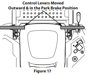
Starting the Engine

1. Operator should be sitting in the tractor seat with the lapbar drive control levers fully out and in the park position. See Figure 17. Refer to Practice Operation for further instructions.
2. Make certain the PTO is in the “OFF” position. Move the choke control or throttle/choke control into the full choke position. Move the throttle control to midway between its slow and fast positions on models with a separate choke control.
Note: If the engine is warmed up, it may not be necessary to choke the engine.
3. Turn the key clockwise to the START position. After the engine starts, release the key. It will return to the RUN position.

4. As the engine warms up, gradually pull the throttle/choke control lever rearward past the choke detent position or slowly disengage the choke on models with a separate choke. Do not use the choke position to enrich the fuel mixture, except as necessary to start the engine.
5. Allow the engine to run for a few minutes at mid-throttle before putting the engine under load.
6. Observe the hour meter/indicator panel. If the battery indicator light or oil pressure light come on, immediately stop the engine. Have the tractor inspected by your authorized service dealer.
Cold Weather Starting
When starting the engine at temperatures near or below freezing, ensure the correct viscosity motor oil is used in the engine and the battery is fully charged.
Start the engine as follows:
1. Be sure the battery is in good condition. A warm battery has much more starting capacity than a cold battery.
2. Use fresh winter grade fuel. Winter grade gasoline has higher volatility to improve starting. Do not use gasoline left over from summer.
3. Follow the previous instruction for Starting the Engine.
Using Jumper Cables To Start Engine

If the battery charge is not sufficient to crank the engine, recharge the battery. If a battery charger is unavailable and the tractor must be started, the aid of a booster battery will be necessary. Connect the booster battery as follows:
1. Connect the end of one cable to the disabled tractor battery’s positive terminal; then connect the other end of that cable to the booster battery’s positive terminal.
2. Connect one end of the other cable to the booster battery’s negative terminal; then connect the other end of that cable to the frame of the disabled tractor, as far from the battery as possible.
3. Start the disabled tractor following the normal starting instructions previously provided; then disconnect the jumper cables in the exact reverse order of their connection.
4. Have the tractor’s electrical system checked and repaired as soon as possible to eliminate the need for jump starting.
Stopping the Engine
1. Disengage the PTO.
2. Move the RH and LH lapbar drive control levers fully outward into the Park Brake engaged position.
3. Move the throttle control to midway between the slow and fast positions.
4. Turn the key to the STOP position and remove the key from the ignition module.
Note: Always remove the key from the ignition module to prevent accidental starting or battery discharge if the equipment is left unattended.
Practice Operation (Initial Use)
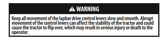
Operating a zero-turn tractor is not like operating a conventional type riding tractor. Although and because a zero turn tractor is more maneuverable, getting used to operating the lapbar drive control levers takes some practice.
It is strongly recommended that you locate a reasonably large, level and open “practice area” where there are no obstructions, pedestrians, or animals. You should practice operating the tractor for a minimum of 30 minutes.
Carefully move (or have moved) the tractor to the practice area. When performing the practice session, the PTO should not be engaged. While practicing, operate the tractor at approximately 1⁄2-3⁄4 throttle and at less than full speed in both forward and reverse. Carefully practice maneuvering the tractor using the instructions in the following section “Driving the Tractor.” Practice until you are confident that you can safely operate the tractor.
Driving the Tractor
1. Adjust the operator’s seat to the most comfortable position that allows you to operate the controls. See seat adjustment in the Assembly & Set-Up section.
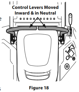
2. Move the RH and LH lapbar drive control levers inward in the neutral position which also disengages the parking brake. Refer to Figure 18.
Note: Lapbar drive control levers must be moved fully inward before pushing forward or backward to ensure brakes are fully disengaged. Parking the tractor on uneven terrain or a hill may cause the brakes to bind and not release fully. In this case the tractor will not drive when the lapbar drive control levers are moved. If this happens, move the lapbar drive control lever in the opposite direction slightly to take the load off the brakes and allow them to release fully.
Note: If the lap bar drive control levers are not even in the neutral position, refer to Maintenance & Adjustments for instructions to adjust the lapbar drive control levers so that they are even
3. Move the throttle to the full throttle position.

4. To drive the tractor, firmly grasp the respective lapbar drive control levers with your right and left hands and continue with Driving the Tractor Forward in the next section.
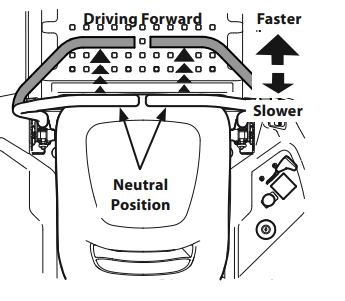
Driving the Tractor Forward
1. Slowly and evenly move both lapbar drive control levers forward. The tractor will start to move forward. See Figure 19.
2. As the lapbar drive control levers are pushed farther forward the speed of the tractor will increase.
3. To slow the tractor move the drive controls lever rearward to attain the desired speed, or move the lapbar drive control levers to the neutral position to stop the tractor.
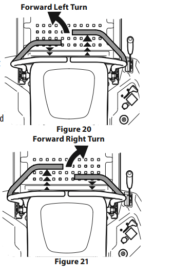
Turning the Tractor While Driving Forward

To turn the tractor while driving forward, move the lapbar drive control levers as necessary so that one drive control lever is rearward of the other. The tractor will turn in the direction of the rearward drive control lever.
1. To turn to the left, move the left drive control lever rearward of the right drive control lever. See Figure 20.
2. To turn to the right, move the right drive control lever rearward of the left lever. See Figure 21.
3. The greater the distance between the two levers, the sharper the tractor will turn.
4. To execute a “pivot turn,” move the turn side drive control lever to the neutral position, while moving the other control lever forward.
Note: Making a “pivot turn” on grass will greatly increase the potential for defacement of the turf
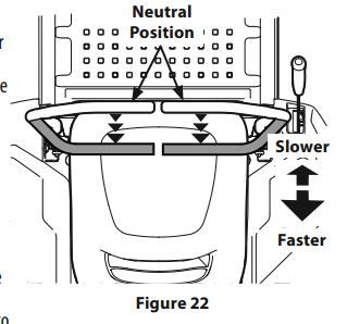
Driving the Tractor In Reverse

1. Slowly and evenly move both lapbar drive control levers rearward. The tractor will start to move in the reverse direction. See Figure 22 .
2. As the lapbar drive control levers are pushed farther rearward the speed of the tractor will increase.
3. To slow the tractor move the lapbar drive control levers forward to attain the desired speed, or move the lapbar drive control levers to the neutral position to stop the tractor.
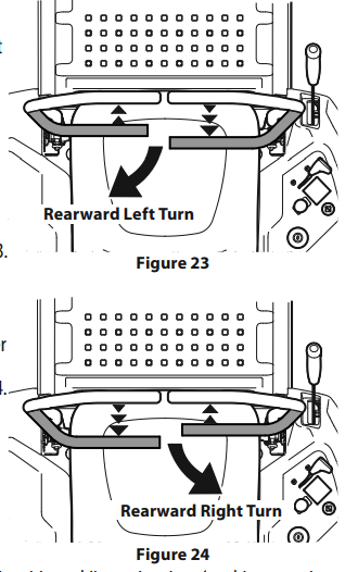
Turning While Driving Rearward
To turn the tractor while driving rearward, move the lapbar drive control levers as necessary so that one drive control lever is forward of the other. The tractor will turn in the direction of the forward lapbar drive control lever.
1. To turn to the left while traveling in reverse, move the left drive control lever forward of the right drive control lever. See Figure 23.
2. To turn to the right while traveling in reverse, move the right drive control lever forward of the left drive control lever. See Figure 24. The greater the distance between the two lapbar drive control levers, the sharper the tractor will turn.
3. To execute a “pivot turn,” move the turn side drive control lever to the neutral position, while moving the other drive control lever rearward.
Note: Making a “pivot turn” on grass will greatly increase the potential for defacement of the turf.
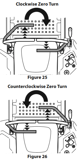
Executing a Zero Turn
1. Stop the forward or reverse motion of the tractor by moving the two lapbar drive control levers to neutral.
2. To turn clockwise, move the left lapbar drive control lever forward while simultaneously moving the right lapbar drive control lever rearward. See Figure 25.
3. To turn counterclockwise, move the lapbar right drive control lever forward while simultaneously moving the left lapbar drive control lever rearward. See Figure 26.
Stopping the Tractor
1. Move both lapbar drive control levers to the neutral position to stop the motion of the tractor.
2. Push the PTO downward to the OFF position.
3. Use the deck lift knob/handle to raise the deck to its highest position.
4. If dismounting the tractor, move the lapbar drive control levers fully outward in the neutral position which also engages the parking brake, move the throttle to the FAST position, turn the key to STOP  and remove the from the ignition module.

Engaging the PTO
Engaging the PTO transfers power to the cutting deck or other (separately available) attachments. To engage the PTO:
1. Move the throttle to the FAST  position.
2. Pull the PTO switch up/out into the ENGAGED (ON) position.
Note: When operating the tractor be certain that the throttle is always in the FAST  position. Operating with the throttle at less than full throttle may lead to premature battery wear and a poor quality cut.
3. To disengage the PTO, push the PTO switch down/in to the DISENGAGED (OFF) position.
Mowing
Note: Do not engage the mower deck when lowered in grass. Premature wear and possible failure of the ‘V” belt and PTO clutch will result. Fully raise the deck or move to a non grassy area before engaging the mower deck.
• Mow across slopes, not up and down. If mowing a slope, start at bottom and work upward to ensure turns are made uphill.
• Do not mow at high ground speed, especially if a mulch kit or grass collector is installed.
• Do not cut the grass too short. Short grass is prone to weed growth and yellows quickly in dry weather.
• Always operate the tractor with the throttle in the FAST position while mowing.
• On the first pass pick a point on the opposite side of the area to be mowed. Follow the point to maintain a straight line
• Engage the PTO and move the throttle control or throttle/choke control to the FAST position.
• Lower the mower deck to the desired height setting.
• For best results it is recommended that the first two laps be cut with the discharge thrown towards the center. After the first two laps, reverse the direction to throw the discharge to the outside for the balance of cutting. This will give a better appearance to the lawn.
• Slowly and evenly push the RH and LH lapbar drive control levers forward to move the tractor forward, and keep the tractor headed directly toward the alignment point.
Note: The speed of the tractor will affect the quality of the mower cut. Mowing at full speed will adversely affect the cut quality. Control the ground speed with the lapbar drive control levers.
• Your tractor is designed to cut normal residential grass of a height no more than 10” (25cm). Do not attempt to mow through unusually tall, dry grass (e.g., pasture) or piles of dry leaves. Dry grass or leaves may contact the engine exhaust and/or build up on the tractor.
• Do NOT attempt to mow heavy brush and weeds or extremely tall grass. Your tractor is designed to mow lawns, NOT clear brush.
• Keep the blades sharp and replace the blades when worn.
• When approaching the other end of the strip, slow down or stop before turning. A U-turn is recommended unless a pivot or zero turn is required.
• Align the mower with an edge of the mowed strip and overlap approximately 3” (7.6 cm). • Direct the tractor on each subsequent strip to align with a previously cut strip.
• To prevent rutting or grooving of the turf, if possible, change the direction that the strips are mowed by approximately 45° for the next and each subsequent mowing.
When stopping the tractor for any reason while on a grass surface, always:
• Move the RH and LH lapbar drive control levers fully outward into the Park Brake engaged position.
• Shut engine off and remove the key.
• Doing so will minimize the possibility of having your lawn ‘‘browned’’ by hot exhaust from your tractor’s running engine.
SERVICE AND MAINTENANCE
MAINTENANCE SCHEDULE
WARNING Before performing any type of maintenance/service, disengage all controls and stop the engine. Wait until all moving parts have come to a complete stop. Disconnect spark plug wire and ground it against the engine to prevent unintended starting. Always wear safety glasses during operation or while performing any adjustments or repairs.
Follow the maintenance schedule given below. This chart describes service guidelines only. Use the Service Log column to keep track of completed maintenance tasks.
Refer to the Engine Operator’s Manual for engine maintenance items listed in the table below.
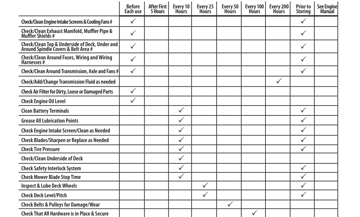
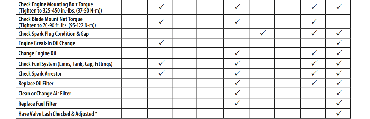
* -- Have this item performed by an authorized service dealer
#-- Perform more often in dry conditions and/or when mulching
Note: This Operator’s Manual covers several models. Tractor features may vary by model. Not all features in this manual are applicable to all tractor models and the tractor depicted may differ from yours.
Post-Operation Tractor Care
After each operation of the tractor, to ensure safe operating conditions refer to Maintenance Schedule chart in this manual for proper tractor care.

Cleaning the Underside of the Deck
Deck Wash System
Your tractor’s deck is equipped with a water port on its surface as part of its deck wash system. Use the deck wash system to rinse grass clippings from the deck’s underside and prevent the buildup of corrosive chemicals. Complete the following steps AFTER EACH MOWING:
1. Attach the nozzle adapter to a standard garden hose connected to a water supply.
2. Move the tractor to an area within reach of the hose where the dispersal of wet grass clippings is acceptable. Disengage the PTO, engage the parking brake and stop the engine.
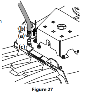
3. Pull back the lock collar (a) of the nozzle adapter (b) and push the nozzle adapter onto the deck wash nozzle (c). Release the lock collar to lock the nozzle adapter on the deck wash nozzle. See Figure 27.
4. Turn on the water supply.
5. From the tractor operator’s seat, start the engine and engage the PTO. Allow to run as needed. Disengage the PTO and stop the engine.
6. Turn off the water supply.
7. Pull back the lock collar of the nozzle adapter to disconnect the nozzle adapter from the deck wash nozzle.
Cleaning the Tractor

Your tractor should be cleaned after each use and under certain conditions, i.e. dry conditions and/or mulching situations, additional cleaning may be necessary.
One of the best ways to keep your tractor running efficiently and to reduce fire risk is to regularly remove debris buildup from the tractor. Follow the recommendations below and contact your authorized dealer with any questions.
• Allow the machine to cool for at leasr five minutes in an open area before cleaning.
Note: Using a pressure washer or garden hose is not recommended for cleaning your tractor other than to clean the underside of the deck. It may cause damage to electrical components, spindles, pulleys, bearings or the engine. The use of water will result in shortened life and reduce serviceability.
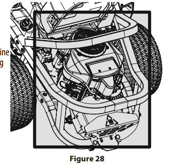
• Keep both sides of transmission cooling slots, exhaust manifold, around fuses, all wiring and harnesses, muffler pipe, muffler shield, engine intake screens and cooling fins, etc clear of grass clippings and leaves. See Figure 28.
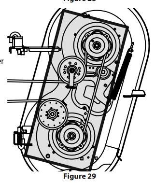
• Clean the top of the mower deck, under the spindle covers and belt area. See Figure 29.
• Clean around and near the transmission, axle and the fan area. See 30.
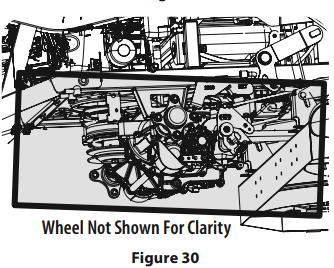
• Debris can accumulate anywhere on the tractor, especially on horizontal surfaces. Additional cleaning may be necessary when mowing in dry conditions or when mulching.
• Fuel leaks/spills, oil leaks/spills and excess lubrication can also become collections sites for debris. Immediate repair and cleaning up oil or fuel spills can help reduce fire hazards.
• In addition to cleaning the tractor before operating and storing, do not attempt to mow unusually tall grass (10” (25.4 cm) or higher), dry grass (e.g., pasture) or piles of dry leaves. Dry grass or leaves may contact the engine exhaust and/or build up on the mower deck presenting a potential fire hazard.
Storing the Tractor
• Allow the machine to cool in an open area for at least five minutes before storing.
• Do not park the tractor near any flammable materials (wood, cloth or chemicals) or any open flames or other potential source of ignition (furnace, water heater or any other type of heater).
• Remove all combustible materials from the tractor before storing. Empty cargo boxes, grass catchers or containers. • Always shut off fuel flow when storing or transporting if tractor is equipped with a fuel shutoff.
• Check the fuel system (lines, tank, cap and fittings) per the maintenance schedule for cracks or leaks. Repair and clean as necessary.
Maintenance Removing the Floor Panel (If equipped)

On some models, the floor panel can be removed for maintenance, service and cleaning. To remove the floor panel: 1.
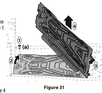
1. Using the multi-tool (if equipped) or a 1/2” socket, remove the hex screw (a) that secures the floor panel in place. See 1 in Figure 31.1.
2. Carefully lift the rear of the floor panel. See 2 in Figure 31.
3. Slide the floor panel rearward to free the front of the floor panel. See 3 in Figure 31.
4. Lift it off the tractor. See 4 in Figure 31.
5. To place the floor panel back on the tractor, carefully put the floor panel back in place and reinstall the hex screw removed in step 1. 1. Using the multi-tool (if equipped) or a 1/2” socket, remove the hex screw (a) that secures the floor panel in place. See 1 in Figure 31.1. Torque to 108-132 in-lbs (12-15 N-m).
Engine

Refer to the Engine Operator’s Manual for all engine maintenance procedures and instructions.
Note : Maintenance, repair, or replacement of the emission control devices and systems which are being done at owner’s expense may be performed by any engine repair establishment or individual. Warranty repairs must be performed by an authorized dealer.
Changing the Engine Oil

Note: The oil filter should be changed at every oil change interval. To complete an oil change, proceed as follows:
1. Locate the oil drain hose (a) on the side of the engine.
2. Place an appropriate oil collection container with at least a 2.5 quart (2.37 liter) capacity below the opening of the oil drain hose, to collect the used oil. Remove the oil fill cap/dipstick (b) from the oil fill tube.
3. While holding the free end of the oil drain hose over the oil collection container, unscrew the square head hose plug (c) from the end of the oil drain hose. See Figure 32. Drain the engine oil into the collection container.
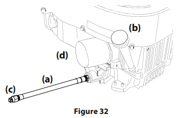
4. After draining the oil, wipe any residual oil from the oil drain hose. Thread the square head hose plug into the oil drain hose fitting and tighten the square head hose plug to 16 ft.-lbs. (22 N-m).
5. Remove the oil filter (d) and drain into the collection container.
6. Replace the oil filter (d), and refill the engine with new oil as instructed in the Engine Operator’s Manual. Note: Place an absorbent towel beneath the oil filter to keep oil off the clutch.
Note: Observe proper disposal laws and regulations for gas, oil, etc. to protect the environment.
Note: Maintenance, repair, or replacement of the emission control devices and systems which are being done at owner’s expense may be performed by any engine repair establishment or individual. Warranty repairs must be performed by an authorized dealer.
Lubrication

• Using a quality lubricating oil, lubricate all lubrication points. Refer to maintenance schedule chart located in this manual for proper service intervals.
Spark Arrestor Maintenance (If Equipped)
Spark arrestor assemblies must be inspected and cleaned periodically (see the service interval chart in this manual). Visually inspect the screen for tears, broken wires or loose welds. Replace the spark arrestor assembly if any of these conditions exist. If the screen is in good condition, clean the screen by brushing away loose dirt or carbon particles.
Tires
Keep the tires inflated to the recommended pressures. Improper inflation will shorten the tire service life. See the tire side wall for proper inflation pressures. Refer to maintenance schedule chart located in this manual for proper service intervals. Observe the following guidelines:
• Do not inflate a tire above the maximum pressure shown on the sidewall of the tire.
• Do not reinflate a tire that has been run flat or seriously under inflated. Have it inspected and serviced by a qualified tire mechanic.
Hydrostatic Transmission
Your zero turn tractor is equipped with two hydrostatic pumps/transaxles. Some models are equipped with a transmission oil expansion reservoir. Under normal operating conditions, the oil level in the expansion reservoirs does not need to be checked and no additional oil is needed.
Checking & Adding Transmission Oil

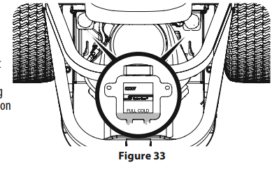
1. Clean the reservoir cap and the area around the cap to prevent debris from contaminating the transmission oil. See Figure 33.
2. Turn the reservoir cap counter-clockwise to remove, then check the oil level in the reservoir. Oil should be visible at the bottom of the cup, but the oil level must NOT be above the “FULL COLD” line. See Figure 33. DO NOT FILL THE RESERVOIR.
3. If necessary to add oil because of some type of leakage, use a quality 20W50 motor oil and add only enough oil to bring the level to the “FULL COLD” line. Reinstall the cap and fully tighten. Note: Prior to the initial operation of the tractor, the oil level in the reservoir may be slightly higher than the maximum due to air in the oil lines. Operation of the tractor will eventually purge the air from the lines and the oil level will settle to the maximum.
4. Repeat the process for the other transmission.
Changing the Transmission Oil & Filter (If Equipped)
Note: Refer to maintenance schedule chart located in this manual for proper service intervals. To change the transmission oil:
1. Remove the cap from the transmission oil expansion reservoir. See Figure 33.
2. Remove the three filter guard screws (a) and the filter guard (b). Clean any loose debris from around the filter (c). See Figure 34.
3. Place and oil drain pan with an eight quart (7.6 liter) capacity below the filter.
4. Remove the filter.
5. When the oil finishes draining, wipe the filter base and apply a thin coat of fresh oil on the filter base.
6. Re-install the filter guard.
7. Remove the top port plug (d) from the transaxles to allow the transaxles to vent during filling. See Figure 34.
8. Using a high-quality 20W50 motor oil, slowly fill the transaxles until oil appears at the top port on the transaxles.
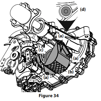
9. Re-install the top port plugs. Torque to 180 in-lbs (20.3 N-m). and continue to fill until the “FULL COLD” line is reached.
10. Replace the reservoir cap and fully tighten.
11. Repeat the process for the other transmission.
12. When replacing the transmission oil, a “purging” procedure should be performed to remove air form the system. The procedure should be performed with the rear wheels off the ground or in an area free of bystanders or objects. To perform the purging procedure:
a. Disengage the brake and open the bypass valve and start the tractor.
b. Move the tractor in forward and reverse 5-6 times.
c. Check the oil level and add as necessary.
d. Repeat steps a-c until the transaxles operate at normal noise levels and normal speeds.
Off-Season Storage
If your tractor is not going to be operated for an extended period of time (thirty days or more), the tractor should be prepared for storage. Store the tractor in a dry and protected location. If stored outside, cover the tractor (including the tires) to protect it from the elements. The procedures outlined below should be performed whenever the tractor is placed in storage.
1. Change the engine oil and filter following the instructions provided in this manual as well as the engine manual packed with this tractor.

2. If storing the tractor for 30 days or more:
a. To prevent gum deposits from forming inside the engine’s carburetor and causing possible malfunction of the engine, the fuel system must be either completely emptied, or the gasoline must be treated with a stabilizer to prevent deterioration.
b. Using a fuel stabilizer for storage between 30 and 90 days:
• Read the product manufacturer’s instructions and recommendations.
• Add to clean, fresh gasoline the correct amount of stabilizer for the capacity (approximately 3 gallons) of the fuel system.
• Fill the fuel tank with treated fuel and run the engine for 2-3 minutes to get stabilized fuel into the carburetor.
• Fuel left in the fuel tank deteriorates and will cause serious starting problems.
c. Emptying the fuel system for storage of more than 90 days:
• Prior to putting the tractor in storage, monitor fuelconsumption with the goal of running the fuel tank empty.
• Run the engine until it begins to stall. Use the choke to keep the engine running until all fuel in the carburetor has been exhausted.
• Referring to the engine manual, drain the fuel from the carburetor bowl.
3. Clean the engine and the entire tractor thoroughly.
Note: Using a pressure washer or garden hose is not recommended for cleaning your tractor other than to clean the underside of the deck. It may cause damage to electrical components, spindles, pulleys, bearings or the engine. The use of water will result in shortened life and reduce serviceability.
4. Fully charge the battery, then disconnect the negative cable at the battery to prevent possible discharge. Recharge the battery periodically when in storage.
Note: Remove the battery if exposed to prolonged periods of sub-freezing temperatures. Store in a cool, dry location where temperatures are above freezing.
5. Lubricate all lubrication points.
Removing The Tractor From Storage
1. Check the engine oil.
2. Fully charge the battery and inflate the tires to the recommended pressure. See tire side wall for proper tire inflation pressure.
3. Fill the fuel tank with clean, fresh gasoline.
4. Start the engine and allow to idle for a few minutes to ensure engine is operating properly.
5. Drive the tractor without a load to make certain all the tractor systems are functioning properly.
Adjustments
Deck Leveling
If the cutting deck appears to be mowing unevenly, leveling adjustments can be performed.

Leveling the Deck (Side-to-Side)
1. Place the deck lift handle or deck lift knob in a middle mowing position and rotate both outside blades so that they are perpendicular with the tractor.
2. Measure the distance from the outside of the left blade tip to the ground and the distance from the outside of the right blade tip to the ground. Both measurements taken should be equal. If they’re not, proceed to the next step.
3. Locate the adjustment bolts (a) on the left and right side of the deck. See 3. Locate the adjustment bolts (a) on the left and right side of the deck. See 3. Locate the adjustment bolts (a) on the left and right side of the deck. See Figure 35.5.
4. Loosen, but do not remove, the jam nuts (b) on the adjustment bolt. Adjust either the right or left adjustment bolt up or down as necessary until the side-to-side heights are equal. See 3. Locate the adjustment bolts (a) on the left and right side of the deck. See 3. Locate the adjustment bolts (a) on the left and right side of the deck. See Figure 35.
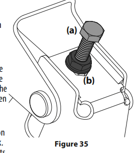
Note: Continue to check the front-to-back leveling as you make the side-toside adjustment as the side-to-side adjustment can affect the front-to-back level. If necessary, adjust front-to-back as instructed previously.
5. When proper adjustment is achieved, re-tighten the jam nuts (b). Tighten to 57 ft-lbs (77.3 N-m). Leveling the Deck (Pitch/Front-to-Rear) The front of the deck should be between 1⁄16-1⁄4” (2-6 mm) lower than the rear of the deck. Adjust if necessary as follows:
1. Park the tractor on a firm, level surface and place the deck lift handle or deck lift knob in a middle position.
2. Rotate the blade nearest the discharge chute so that it is parallel with the tractor.
3. Measure the distance from the front of the blade tip to the ground and the rear of the blade tip to the ground. The first measurement taken should be between 1⁄16-1⁄4” (2-6 mm) less than the second measurement.
4. Determine the approximate distance necessary for proper adjustment and proceed, if necessary.
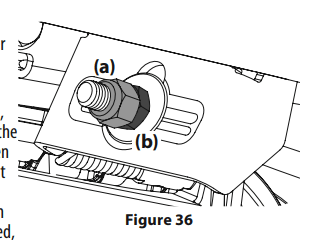
5. To raise the front of the deck, remove the end cap, loosen the outer jam nut (a) then tighten (thread inward) the inner nut (b) against the front hanger bracket. See Figure 36. When proper adjustment is achieved, re-tighten the outer jam nut (a) and replace the end cap.
6. To lower the front of the deck, remove the end cap, loosen the outer jam nut (a) then loosen (thread outward) the inner nut (b), away from the front hanger bracket. See Figure 36. When proper adjustment is achieved, re-tighten the outer jam nut (a) to 57 ft-lbs. (77.28 N-m)and replace the end cap
Adjusting the Deck Wheels

Note: The deck wheels are an anti-scalp feature of the deck and are not designed to support the weight of the cutting deck. The deck wheels should be approximately 1⁄2-1⁄4” (6.35-12.7 mm)above the ground when the deck is set in the desired height setting. To adjust the deck wheels see the Assembly & Set-Up section for instructions
Lapbar Drive Control Lever Stop Adjustment
When the lapbar drive control levers are both fully extended forward to the full-speed position and the tractor drifts left or right, the lapbar drive control lever stop adjustment can be adjusted to sync the wheel speeds. To perform the adjustment, proceed as follows:
1. Identify the side that the tractor is drifting to and adjust the opposite lapbar drive control lever. If the tractor drifts right, adjust the left lapbar drive control lever down (decrease speed) and vice versa.
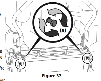
2. Locate the lapbar drive control lever stop adjustment bolts (a) on the front of the seat frame. See 2. Locate the lapbar drive control lever stop adjustment bolts (a) on the front of the seat frame. See Figure 37.
Note: The multi-tool (if equipped) can be used to make this adjustment.
3. To decrease the forward speed, turn the lapbar drive control lever stop adjustment bolts (a)clockwise. To increase the forward speed, turn the lapbar drive control lever stop adjustment bolts (a) counter-clockwise. Turn the lapbar drive control lever stop adjustment bolts (a) in the necessary direction 1⁄4-turn at a time. After turning the lapbar drive control lever stop adjustment bolts (a), check the adjustment by driving the tractor.
4. Continue the adjustment until the wheel speeds are in sync and the tractor drives straight with the drive control levers fully extended forward in the full-speed position.
Note: Make sure the bolts extend through the nuts on the frame to engage the locking feature.
Service
Electrical System
A fuse is installed to protect the tractor’s electrical system from damage caused by excessive amperage. Always use the same capacity fuse for replacement. If the electrical system does not function, check for a blown fuse. If you have a recurring problem with blown fuses, have the tractor’s electrical system checked by your authorized service dealer.
Relays and Switches
There are several safety switches in the electrical system. If a function of the safety interlock system described earlier is not functioning properly, have the electrical system checked by your authorized service dealer.
Parking Brake Adjustment
If the tractor does not come to a complete stop when the control levers are moved fully outward engaging the parking brake, or if the tractor’s rear wheels can roll with the parking brake engaged (and the hydrostatic relief valve open), the brake is in need of adjustment. See your authorized service dealer to have the brake adjusted.
Deck Removal
Remove the tractor deck from the tractor as follows:
1. Move the tractor to a level surface, disengage the PTO, stop the engine, place the RH and LH drive control levers fully outward into the park brake engaged position.
2. There are two methods for removing the belt, to remove the belt by releasing belt tension go on to step 3, to remove the belt by rolling the belt off the PTO pulley skip ahead to step 4.

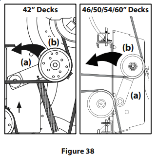
3. Releasing belt tension with the idler pulley:
a. Using the deck lift handle or the deck lift pedal and knob, raise the deck to the position that provides the most horizontal run of the belt between the deck idler pulleys and the PTO pulley on the bottom of the engine.
b. Working from the middle of the tractor, pivot the idler bracket (a) and movable idler pulley (b) rearward just far enough to lift the belt up and over the spindle pulley. See Figure 38.
c. From beneath the rear of the tractor, slide the belt off of the PTO pulley on the bottom of the engine.
d. Lower the deck into the lowest mowing position.
e. Skip ahead to step 5.
4. Rolling the belt off the PTO pulley:
a. Raise the deck to the position that provides the most horizontal run of the belt between the deck idler pulleys and the PTO pulley on the bottom of the engine.
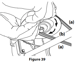
b. Sitting behind the tractor facing forward, reach beneath the tractor to grasp the belt at the front of the PTO pulley.
c. Pull the left side of the belt rearward and downward while manually turning the PTO pulley to the right until the belt rides out onto the edge of the lower sheave of the pulley.
Note: If pulling the right side of the belt, turn the pulley left.
d. While still holding the PTO belt (a) downward, continue turning the PTO pulley (b) until the PTO belt (a) is rolled off the PTO pulley (b). Refer to Figure 39.
e. Lower the deck into the lowest mowing position. f. Move on to step 5.

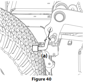
5. On tractors equipped with the deck lift knob, use the deck lift pedal and deck lift knob to place the deck in the lowest position and use the multitool (a) to lock the deck lift components in place as shown in Figure 40. On tractors with a deck lift handle, lower the deck into the lowest position.
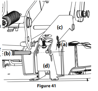
a. Remove the two bow-tie pins (a) from the clevis pins (b) that secure the lift link brackets (c) to the rear deck lift brackets (d) on the deck. Remove the clevis pins (b). See Figure 41.
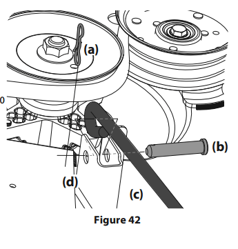
b. Remove the third bow-tie pin (a) from the clevis pin (b) that secures the front deck control rod (c) to the front deck lift bracket (d). Remove the clevis pin (b). See Figure 42.
c. Carefully manuever the deck out from beneath the tractor.
Deck Installation
Install the deck on the tractor as follows:
1. Carefully manuever the the deck under the tractor from the right side, lining up the deck hanger brackets and the deck lift arms on deck lift rod/deck release pin tractors and align the lift link brackets and front deck control rod with the deck lift brackets on three-pin tractors.
2. Once the deck is under the tractor, move the deck to the lowest mowing position.
Note: To line the brackets up properly, it may be necessary to place a small block of wood under each side of the deck.
3. Re-install the applicable hardware for your tractor.
4. Make certain the ‘V’ belt is in the spindle pulleys on the deck; then route the belt rearward beneath the tractor frame, above the transmission tube(s), to the PTO pulley on the bottom of the engine.
5. Raise the deck to the position that provides the most horizontal run of the belt between the deck idler pulleys and the PTO pulley on the bottom of the engine.
6. Make certain the belt is in the spindle pulleys of the deck, and that the backside of the belt is against both the fixed and movable idler pulleys.
7. Sitting behind the tractor, facing forward, make certain the belt is not twisted; then reach beneath the tractor to grasp the belt and pull it toward the PTO pulley.

8. Pull the right side of the PTO belt rearward and place the narrow V-side of the PTO belt into the PTO pulley. See Figure 39.
9. While holding the PTO belt and PTO pulley together, rotate the PTO pulley to the left (See Figure 39). Continue holding and rotating the PTO pulley and PTO belt until the PTO belt is fully rolled into the PTO pulley.
Note: Before using the tractor double-check the belt routing to make sure that the belt has been routed properly
Replacing the Belt
1. Remove the deck from beneath the tractor, (refer to Deck Removal).
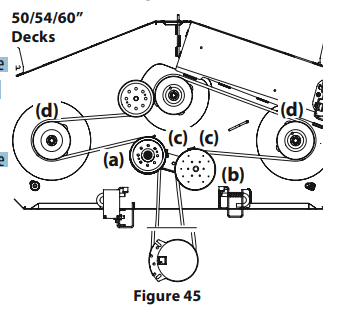
2. Loosen, but do not remove the hardware on the right (a) and left idler pulley (b). Refer to Figure 43 for 42” decks, Figure 44 for 46” decks and Figure 45 for 50”, 54” and 60” decks.
Note: Take note of the position of the belt guards (c) to ensure they are properly re-installed.
Note: On some decks it may be necessary to remove the spindle covers to remove and/ or install the new belt. To remove the spindle covers, remove the screws securing them to the deck.
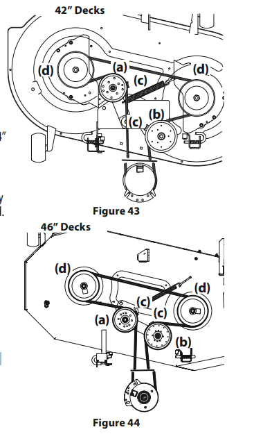
3. Carefully remove the belt from around the idler pulleys (a & b) and the spindle pulleys (d).
4. Install the new belt pulleys as shown and reinstall the belt covers.
5. Place the belt around the idler pulleys removed in step 3 with the “V” side facing in. Once in place, reinstall all the hardware and tighten the flange lock nut to secure the assembly.
6. Route the belt as shown and then reinstall the deck (refer to Deck Installation)
Tractor Blade Care
The cutting blades must be kept sharp at all times. Sharpen the cutting edges of the blades evenly so that the blades remain balanced and the same angle of sharpness is maintained.
If the cutting edge of a blade has already been sharpened many times, or if any metal separation is present, it is recommended that new blades be installed. New blades are available at your authorized dealer. The blades may be removed as follows.
1. Remove the deck from beneath the tractor, (refer to Deck Removal) then gently flip the deck over to expose its underside.
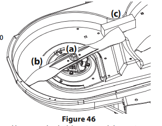
2. Use a 15⁄16” wrench to hold the hex nut on top of the spindle assembly when loosening the hex nut (a) securing the blade (b). A block of wood (c) may be placed between the deck housing and the cutting edge of the blade (b) to help in breaking loose the hex nut (a) securing the blade. See Figure 46.
3. When reinstalling the blades, be sure they are installed so that the wings are pointing upward toward the top of the deck.
4. Tighten the hex nuts (a) to 70-90 ft. lbs. (95-122 N-m).
5. Reinstall the deck (refer to Deck Installation).
Changing the Transmission
Drive Belt Several components must be removed and special tools used in order to change the tractor’s transmission drive belt. See your authorized service dealer to have the transmission drive belt replaced.
Tractor Creeping
Creeping is the slight forward or backward movement of the tractor when the throttle is on and the speed control levers are in the neutral position. If your tractor creeps, see an authorized service dealer.
TROUBLESHOOTING
[image]
This section addresses minor service issues. To locate the nearest authorized service center consult the separate supplement sheet for contact information.
Engine Fails to start
1. PTO/Blade Engage knob engaged.
- Place knob in disengaged (OFF) position.
2. Parking brake not engaged.
3. Spark plug wire disconnected.
- Connect wire to spark plug
4. Throttle control lever not in correct starting position.
- Place Throttle lever to FAST position
5. Fuel tank empty, or stale fuel.
- Fill tank with clean, fresh (less than 30 days old) gas.
6. Blocked fuel line or fuel filter.
- Replace fuel line. See a Sears or other qualified service dealer. Replace fuel filter. See the Service and Maintenance section.
7. Faulty spark plug.
- Clean, adjust gap or replace plug.
8. Engine flooded.
- Crank engine with throttle in FAST position.
9. Fuse(s) blown.
Engine runs erratically
1. Riding mower running with Choke activated.
- Check that the electric choke is working. See a Sears or other qualified service dealer.
2. Spark plug wire loose.
- Connect and tighten spark plug wire.
3. Blocked fuel line or stale fuel.
- Replace fuel line. See a Sears or other qualified service dealer. Fill tank with clean, fresh gasoline and replace fuel filter. See the Service and Maintenance section.
4. Vent in gas cap plugged.
- Clear vent or replace cap if damaged.
5. Water or dirt in fuel system.
- Drain fuel tank. Refill with clean, fresh gasoline. See the Service and Maintenance section.
6. Dirty air cleaner.
- Clean or replace air cleaner paper element or clean foam pre-cleaner.
Engine overheats
1. Engine oil level low
- Fill engine with proper amount and type of oil.
2. Air flow restricted
- Clean grass clippings and debris from around the engine’s cooling fins and blower housing.
Engine hesitates at high RPMs
1. Spark plug gap set too close
- Remove spark plug and adjust gap
Engine idles poorly
1. Fouled spark plug
- Replace spark plug and adjust gap
2. Dirty air cleaner
- Clean or replace air cleaner element and/or clean pre-cleaner
Excessive vibration
1. Cutting blades loose or unbalanced
- Tighten blade and spindle. Balance blade.
2. Damaged, dull, or bent cutting blade
Uneven cut
1. Deck not leveled properly.
- Perform side-to-side deck adjustment.
2. Dull blade.
- Sharpen or replace blade.
3. Uneven tire pressure.
- Check tire pressure in all four tires.