

CRAFTSMAN® is a registered trademark of Stanley Black & Decker, Inc., used under license.
CRAFTSMAN® es una marca registrada de Stanley Black & Decker, Inc., utilizada bajo licencia.
© 2018 CRAFTSMAN U.S. & Canada Only
CRAFTSMAN.com
Form No. 769-16810A
(November 27, 2018)
INSTRUCTION MANUAL | MANUAL DE INSTRUCTIONES
R100 Series
LAWN TRACTOR/TRACTOR CORTACÉSPED
Model Nos. CMXGRAM1130035
CMXGRAM1130040
CMXGRAM1222292
CMXGRAM7368327
IF YOU HAVE QUESTIONS OR COMMENTS, CONTACT US.
SI TIENE DUDAS O COMENTARIOS, CONTÁCTENOS.
1-888-331-4569 WWW.CRAFTSMAN.COM

2
TABLE OF CONTENTS
MODEL NUMBERPRODUCT SPECIFICATIONS
Safe Operation Practices .........................Page 3
Assembly ........................................Page 9
Operation ......................................Page 13
Service and Maintenance ........................Page 19
Off-Season Storage ..............................Page 31
Troubleshooting ............................... Page 32
Español ........................................ Page 33
Warranty Statement ...............Separate Supplement
Engine Series: See Separate Engine Manual
Engine Oil Type: See Separate Engine Manual
Engine Oil Capacity: See Separate Engine Manual
Fuel: Unleaded Gasoline
Model Number ________________________________
Serial Number _________________________________
Date of Purchase _______________________________
Record the model number, serial number,
and date of purchase above.
WARNING
Before using this equipment, read the manual and follow all safety rules and operating instructions. SAVE THESE INSTRUCTIONS!
NOTE: This Operator’s Manual covers several models. Features may vary by model. Not all features in this manual are applicable to all models and the model depicted may differ
from yours.

3
SAFETY INSTRUCTIONS
GENERAL OPERATION
• Read, understand, and follow all instructions on the machine and in the
manual(s) before attempting to assemble and operate. Keep this manual in
a safe place for future and regular reference and for ordering replacement
parts.
• Be familiar with all controls and their proper operation. Know how to stop
the machine and disengage them quickly.
• Never allow children under 14 years old to operate this machine. Children 14
years old and over should read and understand the operation instructions
and safety rules in this manual and should be trained and supervised by a
parent.
• Never allow adults to operate this machine without proper instruction.
• To help avoid blade contact or a thrown object injury, keep bystanders,
helpers, children and pets at least 75 feet from the machine while it is in
operation. Stop machine if anyone enters the area.
• Thoroughly inspect the area where the equipment is to be used. Remove
all stones, sticks, wire, bones, toys, and other foreign objects which could
be picked up and thrown by the blade(s). Thrown objects can cause serious
personal injury.
• Plan your mowing pattern to avoid discharge of material toward roads,
sidewalks, bystanders and the like. Also, avoid discharging material against
a wall or obstruction which may cause discharged material to ricochet back
toward the operator.
• Always wear safety glasses or safety goggles during operation and while
performing an adjustment or repair to protect your eyes. Thrown objects
which ricochet can cause serious injury to the eyes.
• Wear sturdy, rough-soled work shoes and close-fitting slacks and shirts.
Loose fitting clothes and jewelry can be caught in movable parts. Never
operate this machine in bare feet or sandals.
• Be aware of the mower and attachment discharge direction and do not point
it at anyone. Do not operate the mower without the discharge cover or entire
grass catcher in its proper place.
• Do not put hands or feet near rotating parts or under the cutting deck.
Contact with the blade(s) can amputate hands and feet.
• A missing or damaged discharge cover can cause blade contact or thrown
object injuries.
• Stop the blade(s) when crossing gravel drives, walks, or roads and while not
cutting grass.
• Watch for traffic when operating near or crossing roadways. This machine is
not intended for use on any public roadway.
• Do not operate the machine while under the influence of alcohol or drugs.
• Mow only in daylight or good artificial light.
• Never carry passengers.
• Disengage blade(s) before shifting into reverse. Back up slowly. Always look
down and behind before and while backing to avoid a back-over accident.
• Slow down before turning. Operate the machine smoothly. Avoid erratic
operation and excessive speed.
• Disengage blade(s), set parking brake, stop engine and wait until the
blade(s) come to a complete stop before removing grass catcher, emptying
grass, unclogging chute, removing any grass or debris, or making any
adjustments.
• Never leave a running machine unattended. Always turn off blade(s), set
parking brake, stop engine and remove key before dismounting.
• Use extra care when loading or unloading the machine into a trailer or truck.
This machine should not be driven up or down ramp(s), because the machine
could tip over, causing serious personal injury. The machine must be pushed
manually on ramp(s) to load or unload properly.
• Muffler and engine become hot and can cause a burn. Do not touch.
WARNING
This symbol points out important safety instructions which, if not
followed, could endanger the personal safety and/or property of
yourself and others. Read and follow all instructions in this manual
before attempting to operate this machine. Failure to comply with these
instructions may result in personal injury. When you see this symbol, HEED
ITS WARNING!
WARNING
CALIFORNIA PROPOSITION 65
Engine Exhaust, some of its constituents, and certain vehicle components
contain or emit chemicals known to State of California to cause cancer and
birth defects or other reproductive harm.
Battery posts, terminals, and related accessories contain lead and lead
compounds, chemicals known to the State of California to cause cancer and
reproductive harm. Wash hands after handling.
DANGER
This machine was built to be operated according to the safe operation
practices in this manual. As with any type of power equipment,
carelessness or error on the part of the operator can result in serious injury.
This machine is capable of amputating fingers, hands, toes and feet and
throwing debris. Failure to observe the following safety instructions could
result in serious injury or death.
WARNING
Your Responsibility—Restrict the use of this power machine to
persons who read, understand and follow the warnings and instructions in
this manual and on the machine.
SAVE THESE INSTRUCTIONS!

4
SAFETY INSTRUCTIONS
• Check overhead clearances carefully before driving under low hanging tree
branches, wires, door openings etc., where the operator may be struck or
pulled from the machine, which could result in serious injury.
• Disengage all attachment clutches and depress the brake pedal completely
before attempting to start engine.
• Your machine is designed to cut normal residential grass of a height no more
than 12”. Do not attempt to mow through unusually tall, dry grass (e.g.,
pasture) or piles of dry leaves. Dry grass or leaves may contact the engine
exhaust and/or build up on the mower deck presenting a potential fire
hazard.
• Use only accessories and attachments approved for this machine by the
machine manufacturer. Read, understand and follow all instructions
provided with the approved accessory or attachment. For a list of approved
accessories and attachments, call 1-888-331-4569.
• Data indicates that operators, age 60 years and above, are involved in a
large percentage of riding mower-related injuries. These operators should
evaluate their ability to operate the riding mower safely enough to protect
themselves and others from serious injury.
• If situations occur which are not covered in this manual, use care and good
judgment.
SLOPE OPERATION
Slopes are a major factor related to loss of control and tip-over accidents which can result in severe
injury or death. All slopes require extra caution. If you cannot back up the slope or if you feel uneasy on
it, do not mow it.
For your safety, use the Slope Guide included as part of this manual to measure slopes before operating
this machine on a sloped or hilly area. If the slope is greater than 12 degrees as shown on the Slope
Guide, do not operate this machine on that area or serious injury could result.
Do:
• Mow up and down slopes, not across. Exercise extreme caution when
changing direction on slopes.
• Watch for holes, ruts, bumps, rocks, or other hidden objects. Uneven terrain
could overturn the machine. Tall grass can hide obstacles.
• Use slow speed. Choose a low enough speed setting so that you will not have
to stop or shift while on the slope. Tires may lose traction on slopes even
though the brakes are functioning properly. Always keep machine in gear
when going down slopes to take advantage of engine braking action.
• Follow the manufacturer’s recommendations for wheel weights or
counterweights to improve stability.
• Use extra care with grass catchers or other attachments. These can change
the stability of the machine.
• Keep all movement on the slopes slow and gradual. Do not make sudden
changes in speed or direction. Rapid engagement or braking could cause
the front of the machine to lift and rapidly flip over backwards which could
cause serious injury.
• Avoid starting or stopping on a slope. If tires lose traction, disengage the
blade(s) and proceed slowly straight down the slope.
Do Not:
• Do not turn on slopes unless necessary; then, turn slowly and gradually
downhill, if possible.
• Do not mow near drop-offs, ditches or embankments. The mower could
suddenly turn over if a wheel is over the edge of a cliff, ditch, or if an edge
caves in.
• Do not try to stabilize the machine by putting your foot on the ground.
• Do not use a grass catcher on steep slopes.
• Do not mow on wet grass. Reduced traction could cause sliding.
• Do not attempt to coast downhill. Over-speeding may cause the operator to
lose control of the machine resulting in serious injury or death.
• Do not tow heavy pull behind attachments (e.g. loaded dump cart, lawn
roller, etc.) on slopes greater than 5 degrees. When going down hill, the
extra weight tends to push the tractor and may cause you to loose control
(e.g. tractor may speed up, braking and steering ability are reduced,
attachment may jack-knife and cause tractor to overturn).
CHILDREN
Tragic accidents can occur if the operator is not alert to the presence of children. Children are often
attracted to the machine and the mowing activity. They do not understand the dangers. Never assume
that children will remain where you last saw them.
• Keep children out of the mowing area and in watchful care of a responsible
adult other than the operator.
• Be alert and turn machine off if a child enters the area.
• Before and while backing, look behind and down for small children.
• Never carry children, even with the blade(s) shut off. They may fall off and be
seriously injured or interfere with safe machine operation.
• Use extreme care when approaching blind corners, doorways, shrubs, trees
or other objects that may block your vision of a child who may run into the
machine.
• To avoid back-over accidents, always disengage the cutting blade(s) before
shifting into Reverse. If equipped, the “Reverse Caution Mode” (blades
operate while machine rides in reverse) should not be used when children or
others are around.
• Keep children away from hot or running engines. They can suffer burns from
a hot muffler.
• Remove key when machine is unattended to prevent unauthorized
operation.
Never allow children under 14 years of age to operate this machine. Children 14 and over should read
and understand the instructions and safe operation practices in this manual and on the machine and
should be trained and supervised by an adult.
TOWING
• Tow only with a machine that has a hitch designed for towing. Do not attach
towed equipment except at the hitch point.
• Follow the manufacturers recommendation for weight limits for towed
equipment and towing on slopes.
• Never allow children or others in or on towed equipment.
• On slopes, the weight of the towed equipment may cause loss of traction and
loss of control.

5
SAFETY INSTRUCTIONS
• Always use extra caution when towing with a machine capable of making
tight turns (e.g. “zero-turn” ride-on mower). Make wide turns to avoid
jack-knifing.
• Travel slowly and allow extra distance to stop.
• Do not coast downhill.
SERVICE
Safe Handling of Gasoline:
To avoid personal injury or property damage use extreme care in handling
gasoline. Gasoline is extremely flammable and the vapors are explosive.
Serious personal injury can occur when gasoline is spilled on yourself or your
clothes which can ignite. Wash your skin and change clothes immediately.
• Use only an approved gasoline container.
• Never fill containers inside a vehicle or on a truck or trailer bed with a plastic
liner. Always place containers on the ground away from your vehicle before
filling.
• When practical, remove gas-powered equipment from the truck or
trailer and refuel it on the ground. If this is not possible, then refuel such
equipment on a trailer with a portable container, rather than from a gasoline
dispenser nozzle.
• Keep the nozzle in contact with the rim of the fuel tank or container opening
at all times until fueling is complete. Do not use a nozzle lock-open device.
• Extinguish all cigarettes, cigars, pipes and other sources of ignition.
• Never fuel machine indoors.
• Never remove gas cap or add fuel while the engine is hot or running. Allow
engine to cool at least two minutes before refueling.
• Never over fill fuel tank. Fill tank to no more than ½ inch below bottom of
filler neck to allow space for fuel expansion.
• Replace gasoline cap and tighten securely.
• If gasoline is spilled, wipe it off the engine and equipment. Move machine to
another area. Wait 5 minutes before starting the engine.
• To reduce fire hazards, keep machine free of grass, leaves, or other debris
build-up. Clean up oil or fuel spillage and remove any fuel soaked debris.
• Never store the machine or fuel container inside where there is an open
flame, spark or pilot light as on a water heater, space heater, furnace, clothes
dryer or other gas appliances.
• Allow a machine to cool at least five minutes before storing.
General Service
• Never run an engine indoors or in a poorly ventilated area. Engine exhaust
contains carbon monoxide, an odorless, and deadly gas.
• Before cleaning, repairing, or inspecting, make certain the blade(s) and all
moving parts have stopped. Disconnect the spark plug wire and ground against
the engine to prevent unintended starting.
• Periodically check to make sure the blades come to complete stop within
approximately (5) five seconds after operating the blade disengagement
control. If the blades do not stop within the this time frame, your machine
should be serviced professionally by a qualified service dealer.
• Check brake operation frequently as it is subjected to wear during normal
operation. Adjust and service as required.
• Check the blade(s) and engine mounting bolts at frequent intervals for
proper tightness. Also, visually inspect blade(s) for damage (e.g., excessive
wear, bent, cracked). Replace the blade(s) with the original equipment
manufacturer’s (O.E.M.) blade(s) only, listed in this manual. Use of parts
which do not meet the original equipment specifications may lead to
improper performance and compromise safety!
• Mower blades are sharp. Wrap the blade or wear gloves, and use extra
caution when servicing them.
• Keep all nuts, bolts, and screws tight to be sure the equipment is in safe
working condition.
• Never tamper with the safety interlock system or other safety devices. Check
their proper operation regularly.
• After striking a foreign object, stop the engine, disconnect the spark plug
wire(s) and ground against the engine. Thoroughly inspect the machine for
any damage. Repair the damage before starting and operating.
• Never attempt to make adjustments or repairs to the machine while the
engine is running.
• Grass catcher components and the discharge cover are subject to wear
and damage which could expose moving parts or allow objects to be
thrown. For safety protection, frequently check components and replace
immediately with original equipment manufacturer’s (O.E.M.) parts only,
listed in this manual. Use of parts which do not meet the original equipment
specifications may lead to improper performance and compromise safety!
• Do not change the engine governor settings or over-speed the engine. The
governor controls the maximum safe operating speed of the engine.
• Maintain or replace safety and instruction labels, as necessary.
• Observe proper disposal laws and regulations for gas, oil, etc. to protect the
environment.
• According to the Consumer Products Safety Commission (CPSC) and the U.S.
Environmental Protection Agency (EPA), this product has an Average Useful
Life of seven (7) years, or 270 hours of operation. At the end of the Average
Useful Life, buy a new machine or have the machine inspected annually by
a qualified service dealer to ensure that all mechanical and safety systems
are working properly and not worn excessively. Failure to do so can result in
accidents, injuries or death.
DO NOT MODIFY ENGINE
To avoid serious injury or death, do not modify engine in any way. Tampering
with the governor setting can lead to a runaway engine and cause it to
operate at unsafe speeds. Never tamper with factory setting of engine
governor.

6
SAFETY INSTRUCTIONS
SPARK ARRESTOR
WARNING
This machine is equipped with an internal combustion engine and should
not be used on or near any unimproved forest-covered, brush-covered or
grass-covered land unless the engine’s exhaust system is equipped with a
spark arrestor meeting applicable local or state laws (if any).
If a spark arrestor is used, it should be maintained in effective working order
by the operator. In the State of California the above is required by law (Section
4442 of the California Public Resources Code). Other states may have similar
laws. Federal laws apply on federal lands.
A spark arrestor for the muffler is available through your nearest qualified
service dealer.
For location and purchase information, call 1-888-331-4569.
NOTICE REGARDING EMISSIONS
Engines which are certified to comply with California and federal EPA
emission regulations for SORE (Small Off Road Equipment) are certified
to operate on regular unleaded gasoline, and may include the following
emission control systems: Engine Modification (EM), Oxidizing Catalyst (OC),
Secondary Air Injection (SAI) and Three Way Catalyst (TWC) if so equipped.
SAFETY SYMBOLS
This page depicts and describes safety symbols that may appear on this product. Read, understand, and follow all instructions on the machine before
attempting to assemble and operate.
Symbol Description
READ THE OPERATOR’S MANUAL(S)
Read, understand, and follow all instructions in the manual(s) before attempting to assemble and
operate
DANGER— ROTATING BLADES
Never carry passengers. Never carry children, even with the blades off.
DANGER— ROTATING BLADES
To avoid a back-over accident, keep children away from the machine while it is in operation.
WARNING— ROTATING BLADES
Do not put hands or feet near rotating parts or under the cutting deck. Contact with the blade(s) can
amputate hands and feet.
DANGER— ROTATING BLADES
Always look down and behind before and while backing to avoid a back-over accident.
WARNING—THROWN OBJECTS
This machine may pick up and throw and objects which can cause serious personal injury.
WARNING—THROWN OBJECTS
This machine may pick up and throw and objects which can cause serious personal injury.

7
SAFETY INSTRUCTIONS
Symbol Description
BYSTANDERS
Keep bystanders, helpers, children and pets at least 75 feet from the machine while it is in operation.
WARNING— SLOPE OPERATION
Do not operate this machine on a slope greater than 12 degrees.
WARNING— HOT SURFACE
Engine parts, especially the muffler, become extremely hot during operation. Allow engine and
muffler to cool before touching.
DANGER — ROTATING BLADES
To reduce the risk of injury, keep hands and feet away. Do not operate unless discharge cover or grass
catcher is in its proper place. If damaged, replace immediately.
WARNING— CARBON MONOXIDE
Never run an engine indoors or in a poorly ventilated area. Engine exhaust contains carbon
monoxide, an odorless and deadly gas.
DANGER— ROTATING BLADES
Do not step on the cutting deck.
WARNING: Your Responsibility—Restrict the use of this power machine to persons who read, understand and follow
the warnings and instructions in this manual and on the machine.
SAVE THESE INSTRUCTIONS!
8
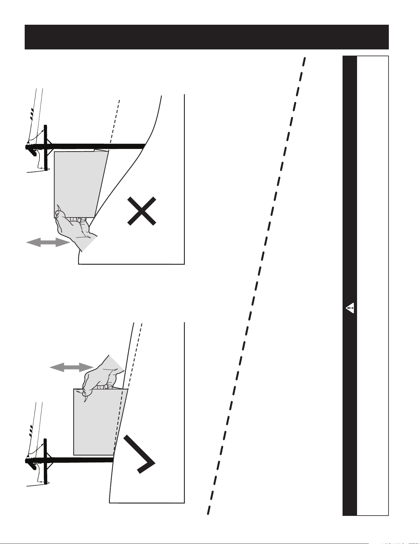
SLOPE GAUGE
(OK) (TOO STEEP)
USE THIS SLOPE GAUGE TO DETERMINE
IF A SLOPE IS TOO STEEP FOR SAFE OPERATION!
To check the slope, proceed as follows:
1. Remove this page and fold along the dashed line.
2. Locate a vertical object on or behind the slope (e.g. a pole, building, fence, tree, etc.)
3. Align either side of the slope gauge with the object (See Figure 1 and Figure 2 ).
4. Adjust gauge up or down until the left corner touches the slope (See Figure 1 and Figure 2).
5. If there is a gap below the gauge, the slope is too steep for safe operation (See Figure 2 above).
12° dashed line
Figure 2Figure 1
12° Slope
12° Slope
WARNING
Slopes are a major factor related to tip-over and roll-over accidents which can result in severe injury or death. Do not operate machine
on slopes in excess of 12 degrees. All slopes require extra caution. If you cannot back up the slope or if you feel uneasy on it, do not
mow it. Always mow up and down the face of slopes, never mow across the face of slopes.
Contents of Hardware Pack
Before beginning installation, remove all the contents from the crate and all the
hardware from the pack to make sure everything is present. Hardware is listed
below. Part numbers are shown in parentheses.
• Hitch Plate
• Seat Mounting Bracket (with two shoulder bolts & lock nuts installed)
Recommended Tools for Assembly
• 3/8” Wrench (or socket) • 9/16” Socket
• 1/2” Wrench (or socket) • 7/16” wrench
• 5/8” Wrench (or socket) • Phillips Screw Driver
• 1/4” Drive Ratchet
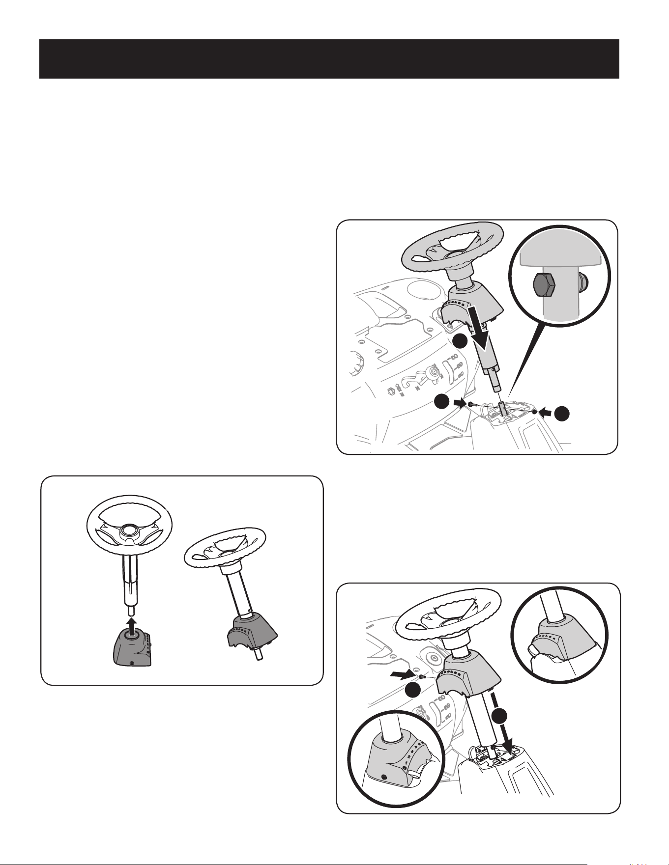
Installing The Steering Wheel Assembly
If the steering wheel assembly for your tractor did not come already installed,
follow the steps below:
1. Slide the pedestal cap onto the steering shaft so that when the steering
shaft is installed on the tractor, the pedestal cap will be upright as shown in
Figure 1.
Figure 1
2. Remove the shoulder bolt and lock nut from the steering shaft on the tractor
and retain for later steps.
3. With the steering wheel assembly upright and positioned over the lower
steering shaft on the tractor, align the steering wheel so that with the
tractor wheels straight, the large opening on the steering wheel is facing
forward.
Contents of Crate
• One Riding Mower • One Seat Assembly • One Discharge Chute Assembly
• One Steering Wheel/Shaft Assembly • One Rear Engine Cover • One Hardware Pack
• One Rear Hitch Plate • One Oil Drain Sleeve
• One Riding Mower Operator’s Manual • One Steering Pedestal Cap
4. Lower the steering wheel assembly onto the lower steering shaft (1) and
secure with bolt and lock nut (2) previously removed. See Figure 2.
1
2
2
Figure 2
5. Tighten the shoulder bolt and lock nut using a 9/16” wrench and
7/16”wrench or socket.
6. Remove the pedestal cap mount screw factory installed and located on the
tractor’s steering console. Retain the screw for later instructions.
7. Slide the Pedestal cap down onto the tractor (1) and slightly rotate to the
right to clip into place. Secure the pedestal with the screw (2) previously
removed. See Figure 3.
1
2
Figure 3
9
ASSEMBLY
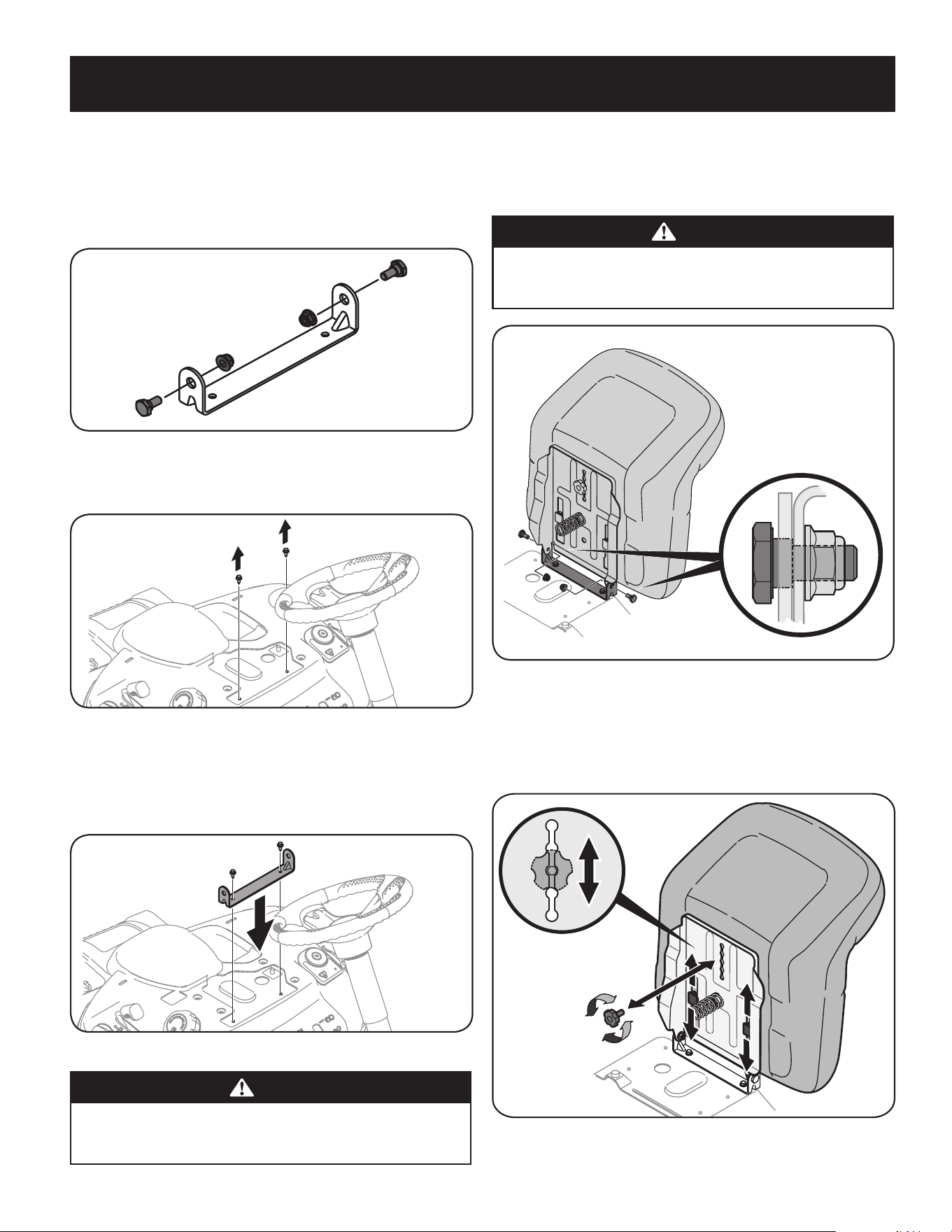
Attaching The Seat
If the seat for your tractor was not attached at the factory, follow the applicable
instructions below to attach it.
1. Remove the shoulder bolts and lock nuts from the seat mounting bracket
included in your hardware pack. See Figure 4.
Figure 4
2. Remove the two self-tapping screws factory installed on the tractor. See
Figure 5.
Figure 5
3. Align the seat bracket in place over the holes from where the self-tapping
screws were removed, as shown in Figure 6.
4. Using a 1/4-inch drive ratchet with a 3/8” socket, secure the seat bracket with
the self-tapping screws removed in Step 2. See Figure 6.
Figure 6
CAUTION
Do not use any type of power tool (e.g. impact gun or electric drill with nut
driver attached) when tightening the self-tapping bolts to attach the seat
bracket.
5. Position the seat assembly over the seat mounting bracket, aligning the
holes provided.
6. Install the two shoulder bolts and lock nuts removed from the seat mounting
bracket in Step 1. See Figure 7.
CAUTION
Do not use any type of power tool (e.g. impact gun or electric drill with nut
driver attached) when tightening the self-tapping bolts to attach the seat
bracket.
Figure 7
Seat Adjustment
1. To adjust the position of the seat, remove the adjustment knob on the
bottom of the seat. Slide the seat forward or backward as desired. Reinstall
the adjustment knob. Refer to Figure 8.
Figure 8
10
ASSEMBLY
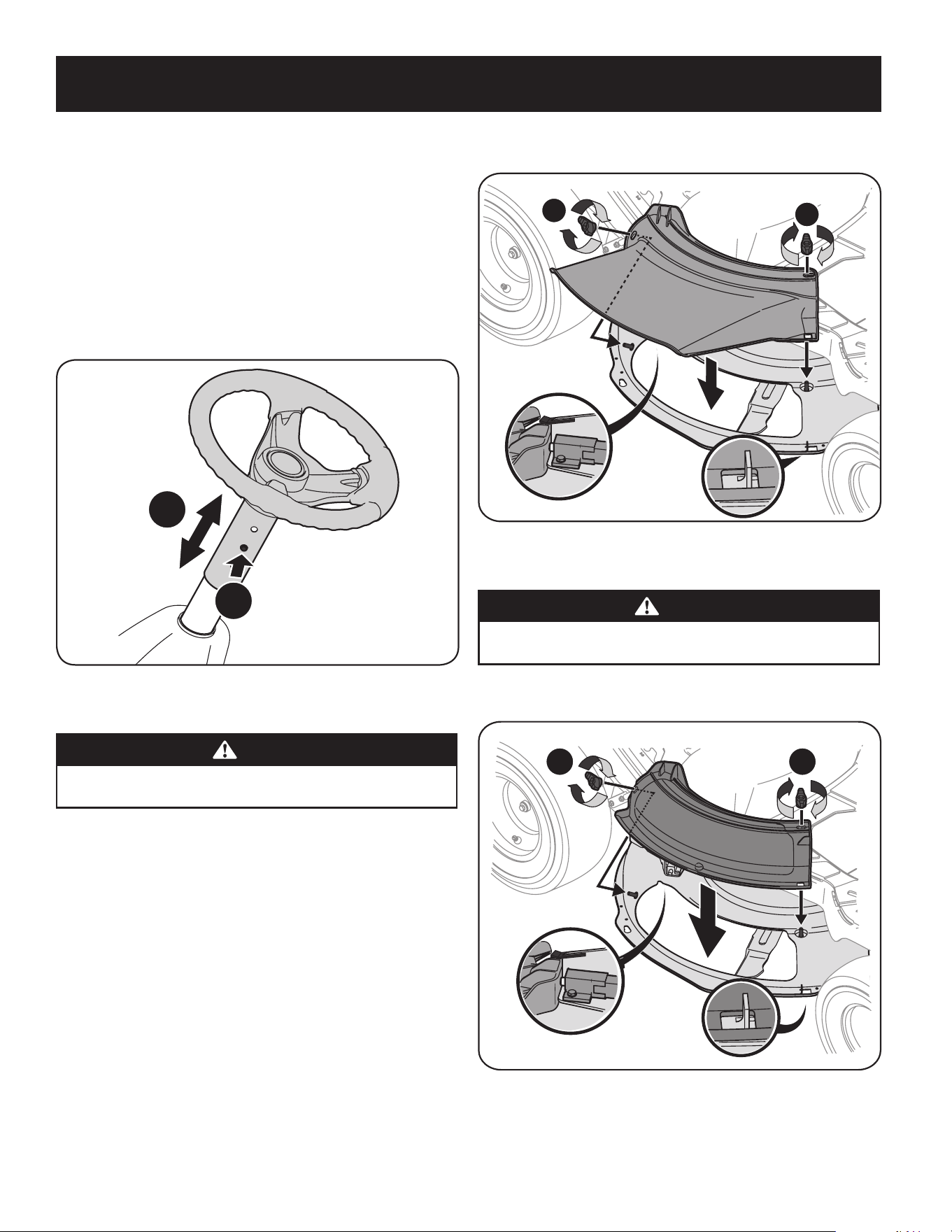
Steering wheel height adjustment
To adjust the height of the steering wheel, this unit is equipped with a telescoping
steering column. To adjust the height of the steering wheel:
1. Sit in the operator’s seat and place your hands on the steering wheel.
2. Push the button (a) on the steering column and raise or lower the steering
wheel (b) to the desired position. See Figure 9.
Note: Once the desired position is achieved, lift up and down on the steering wheel
to make sure it locks into place and the button (a) on the steering column releases
into a locked position. Do not operate this unit unless the steering column is in a
locked position.
a
b
Figure 9
Installing The Deck Chute
WARNING
NEVER operate this tractor without either the mulch plug or deck chute
installed.
1. Remove the wing knobs installed on the mowing deck and retain for later
installation.
2. Install the deck chute into the deck discharge opening on the deck. The rear
of the chute should be under the tab on the rear deck bracket. See inset in
Figure 10. The studs on the deck surface will fit through the holes on the
upper portion of the deck chute. The small tab on the deck lip area will fit
through the square cutout on the lower portion of the deck chute. See inset
of Figure 10.
Note: Make certain that the upper-rear portion of deck chute is depressing
the safety switch located on the deck surface and under the tab on the rear
deck bracket. The engine will not start without the deck chute properly in
place.
3. Secure the deck chute by tightening the wing knobs removed earlier. See
Figure 10.
1
2
Figure 10
Installing the Mulch Plug
WARNING
NEVER operate this tractor without either the mulch plug or deck chute
installed.
1. Remove the wing knobs installed on the mowing deck and retain for later
installation. See Figure 11.
1
2
Figure 11
11
ASSEMBLY
2. Install the mulch plug into the deck discharge opening on the deck. The rear
of the mulch plug should be under the tab on the rear deck bracket. The
studs on the deck surface will fit through the holes on the upper portion of
the mulch plug. The small tab on the deck lip area will fit through the square
cutout on the lower portion of the mulch plug. See Figure 11.
Note: Make certain that the upper-rear portion of mulch plug is depressing
the safety switch located on the deck surface and under the tab on the rear
deck bracket. The engine will not start without the mulch plug properly in
place.
3. Secure the mulch plug by tightening the wing knobs removed in step 1.
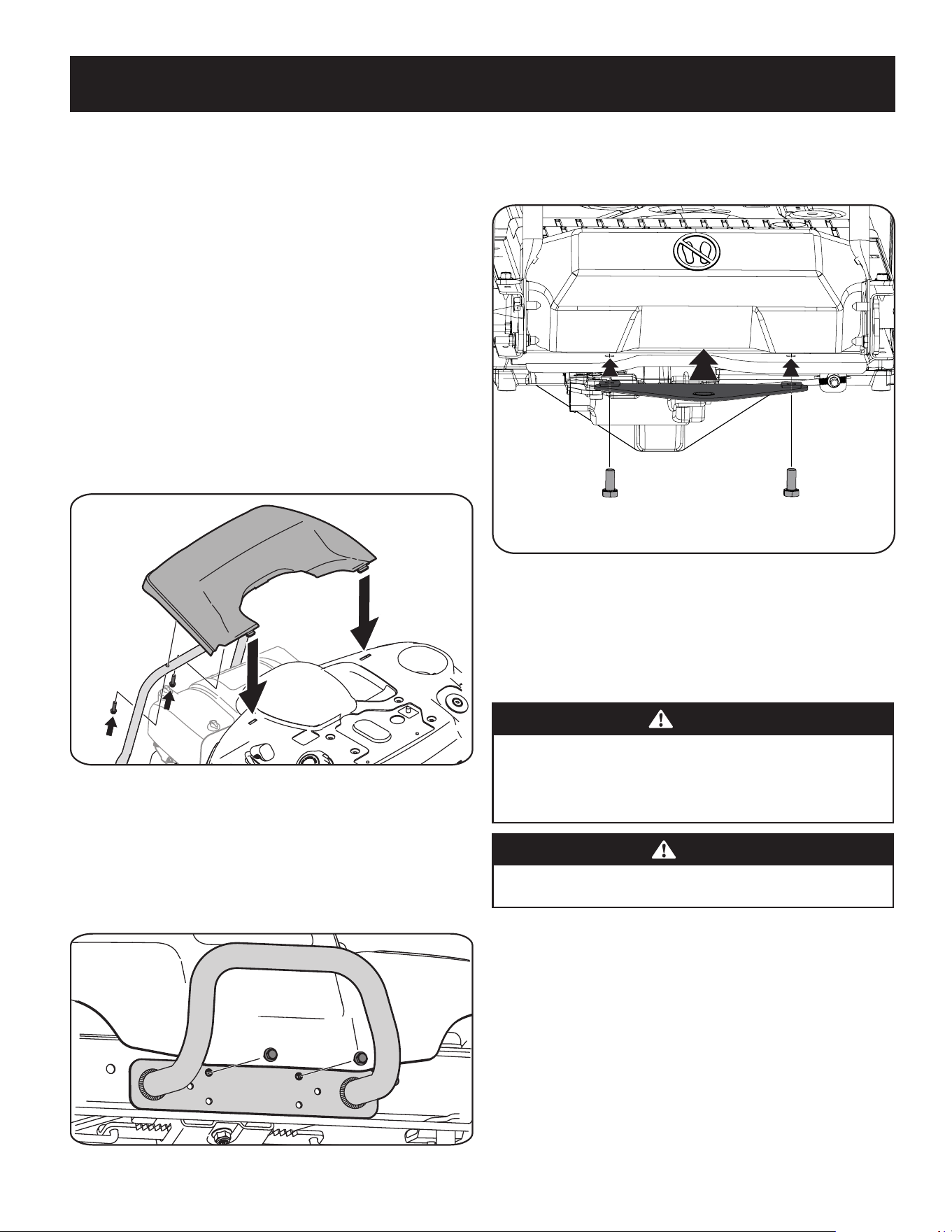
Install The Rear Engine Cover
1. Remove the two factory installed hex screws located on the rear engine
cover mounting bracket. Retain the screws for later instructions. See
Figure 12.
2. Install the rear engine cover by positioning it in place as shown in Figure 12.
Tip the engine cover forward to fit it into the slots provided, then rotate it
backwards to align the mounting holes.
Figure 12
3. Secure the cover with the two hex screws previously removed. Do not to
over-tighten.
Installing the Bumper
1. Remove the two screws as shown in Figure 13.
2. Position the bumper over the mounting holes and secure using the hardware
removed in Step 1, as shown in Figure 13.
Figure 13
Installing the Hitch Plate
1. Slide the hitch plate in between the frame and the rear cover on your rider.
See Figure 14.
Figure 14
2. When the holes in the hitch plate and the frame are aligned, install the two
hex screws from the manual bag up through the frame and into the hitch
plate. See Figure 14.
3. Securely tighten the hitch plate.
Connecting the Battery Cables
WARNING
CALIFORNIA PROPOSITION 65
Battery posts, terminals, and related accessories contain lead and lead
compounds, chemicals known to the State of California to cause cancer and
reproductive harm. Wash hands after handling.
CAUTION
When attaching battery cables, always connect the POSITIVE (Red) wire to
its terminal first, followed by the NEGATIVE (Black) wire.
For shipping reasons, both battery cables on your equipment may have been left
disconnected from the terminals at the factory. To connect the battery cables,
proceed as follows:
NOTE: The positive battery terminal is marked Pos. (+). The negative battery
terminal is marked Neg. (–).
1. Remove the factory installed hex bolts and hex nuts located on the end of
the wiring harness. Retain the hardware for later instructions.
2. Remove the plastic cover, if present, from the positive battery terminal and
attach the red cable to the positive battery terminal (+) with one of the hex
bolt and hex nuts, using a 7/16 inch wrench and socket wrench. See Figure 11.
12
ASSEMBLY

3. Remove the plastic cover, if present, from the negative battery terminal
and attach the black cable to the negative battery terminal (–) with the
remaining hex bolt and hex nut, using a 7/16 inch wrench and socket
wrench. See Figure 15.
4. Position the red rubber boot over the positive battery terminal to help
protect it from corrosion.
NOTE: If the battery is put into service after the date shown on top/side of battery,
charge the battery as instructed in the Maintenance section of this Operator’s
Manual prior to operating the tractor.
Figure 15
Gas & Oil
NOTE: The engine is shipped without gasoline and with motor oil in the engine.
However, you MUST check the oil level before operating. Be careful not to overfill.
Running the engine with insufficient oil can cause serious engine damage and void
the engine warranty.
WARNING
Always keep hands and feet clear of equipment moving parts. Do not use a
pressurized starting fluid. Vapors are flammable.
Oil Recommendations
Before starting engine, check oil level, capacity is 1700 ml/57.5 fl. oz. Refer to
viscosity chart in Figure 3-1 for oil recommendations. Do not over-fill. Use a
4-stroke, or an equivalent high detergent, premium quality motor oil certified
to meet or exceed U.S. automobile manufacturer’s requirements for service
classification of a minimum level SJ (higher letter ratings are acceptable such as SL
and SM grades). Motor oil will display this designation on the container.
SAE 10W-30 is recommended for general, all temperature use. If single viscosity oil
is used, select the appropriate viscosity for the average temperature in your area
from the chart below.
CAUTION
Do not use non-detergent oil or 2-stroke engine oil. It could shorten the
engine’s service life.
NOTE: A 5w30 synthetic oil may be used to improve start ability for cold weather
(temperatures below 40 F).
-30º -20º -10º 0º
0º 15º 30º 50º 70º 85º 105º
10º 20º 30º 40º
-20º
(ºC)
(ºF)
5W-30
30
10W-30
Synthetic 5W-30
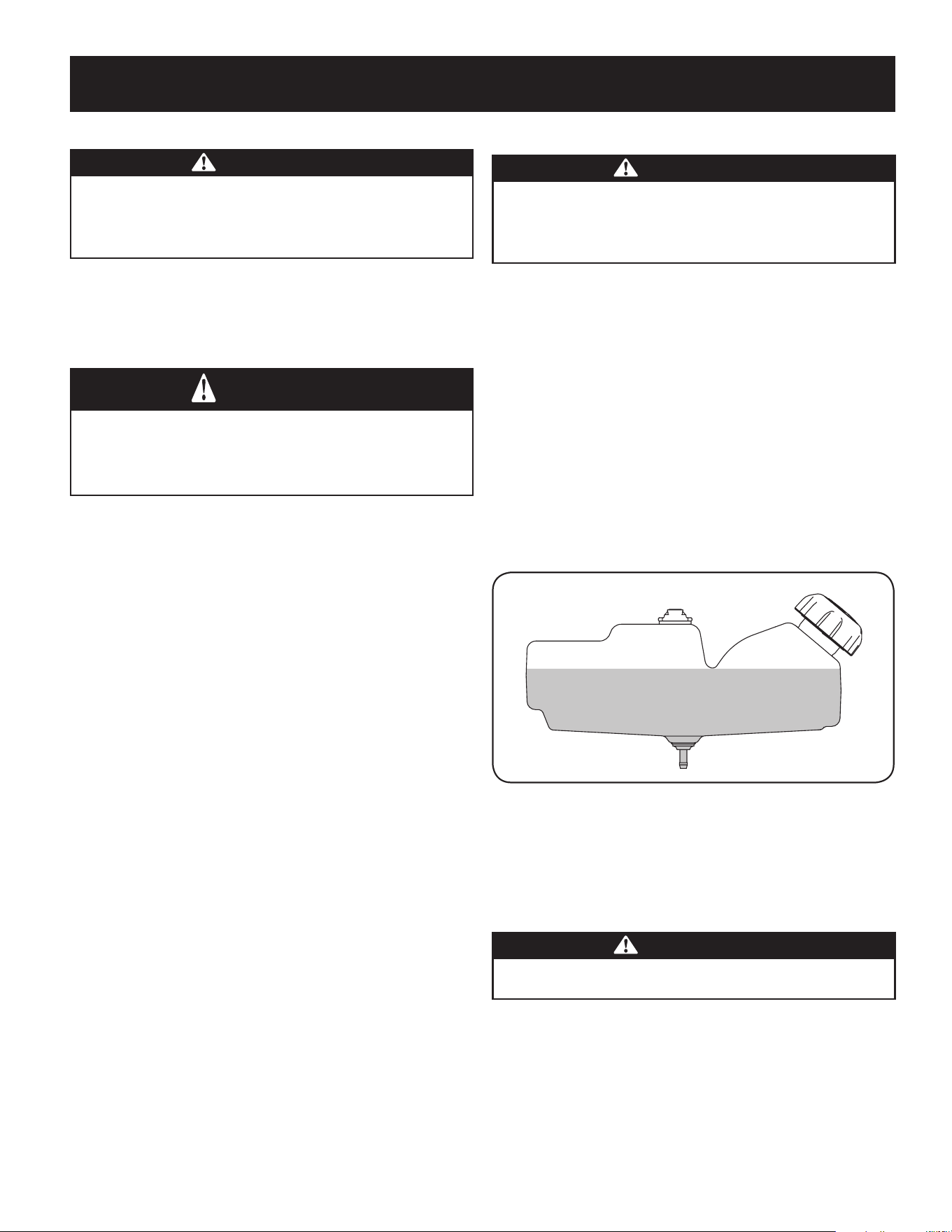
Checking The Oil Level
NOTE: Be sure to check the oil while on a level surface with the engine stopped.
1. Remove the oil filler cap/dipstick and wipe the dipstick clean.
2. Insert the dipstick into the oil filler neck. Turn the dipstick 1/4 turn into the
locked position to fully seat. See Figure 16.
3. Remove dipstick to check the oil level.
4. If the level is low, slowly add oil until the reading is at the upper level on the
dipstick. See Figure 16 inset.
5. Reinsert the dipstick and turn to locked position before starting the engine.
Upper
Level
Oil Fill
Cap/Dipstick
Figure 16
NOTE: Do not overfill. Overfilling with oil may cause smoking, hard starting,
spark plug fouling, or oil saturation of air cleaner.
13
ASSEMBLY
Fuel Requirements
CAUTION
Operating the engine with E85 fuel, an oil/gasoline mixture, dirty gasoline,
or gasoline over 30 days old without fuel stabilizing additive may result
in damage to your engine’s carburetor. Subsequent damage would not be
covered under the Craftsman warranty.
Use automotive gasoline (unleaded or low leaded to minimize combustion chamber
deposits) with a minimum of 87 octane. Gasoline with up to 10% ethanol or 15%
MTBE (Methyl Tertiary Butyl Ether) can be used. Never use an oil/gasoline mixture
or dirty gasoline. Avoid getting dirt, dust, or water in the fuel tank. DO NOT use E85
gasoline.
WARNING
Use extreme care when handling gasoline. Gasoline is extremely flammable
and the vapors are explosive. Never fuel machine indoors or while the
engine is hot or running. Extinguish cigarettes, cigars, pipes, and other
sources of ignition.
NOTE : Purchase gasoline in small quantities. Do not use gasoline left over from the
previous season, to minimize gum deposits in the fuel system.
• This engine is certified to operate on unleaded gasoline. For best results, fill
the fuel tank with only clean, fresh, unleaded gasoline with a pump sticker
octane rating of 87 or higher.
• Gasohol (up to 10% ethyl alcohol, 90% unleaded gasoline by volume) is an
approved fuel. Other gasoline/alcohol blends, such as E85, are not approved.
• Methyl Tertiary Butyl Ether (MTBE) and unleaded gasoline blends (up to a
maximum of 15% MTBE by volume) are approved fuels. Other gasoline/ether
blends are not approved.
• Fill fuel tank outdoors or in well-ventilated area.
• Do not overfill fuel tank. Fill tank to no more than 1/2 inch below bottom of
filler neck to allow space for fuel expansion.
• Never remove gas cap or add fuel while the engine is hot or running. Allow
engine to cool at least two minutes before refueling.
• If gasoline is spilled, wipe it off the engine and equipment. Move machine to
another area. Wait 5 minutes before starting the engine.
To Add Gasoline
NOTE: The tractor is fitted with a tethered, ratcheting fuel cap. STOP filling the tank
once the fuel is seen inside the filler neck. This ensures that a proper expansion
volume is created, otherwise the fuel can overflow creating a hazardous situation.
Do NOT top off the fuel tank.
• Refuel in a well-ventilated area with the engine stopped. Do not smoke or
allow flames or sparks in the area where the engine is refueled or where
gasoline is stored.
• Do not overfill the fuel tank. After refueling, make sure the tank cap is closed
properly and securely.
• Be careful not to spill fuel when refueling. Spilled fuel or fuel vapor may
ignite. If any fuel is spilled, make sure the area is dry before starting the
engine.
• Avoid repeated or prolonged contact with skin or breathing of vapor.
Adding Fuel
WARNING
An adult should fuel this engine. NEVER allow children to refuel its engine.
Gasoline (fuel) vapors are highly flammable and can explode. Fuel vapors
can spread and be ignited by a spark or flame many feet away from engine.
To prevent injury or death from fuel fires, follow these instructions:
• DO NOT use leaded fuel.
• Fuel must be fresh and clean. NEVER use fuel left over from last season or
stored for long periods.
• NEVER mix oil with fuel.
• DO NOT use fuel containing Methanol (Wood Alcohol)
NOTE: Before refueling, allow engine to cool two minutes.
1. Turn the engine off and let engine cool at least 2 minutes before removing
the fuel cap. The gasoline tank is located under the seat. The fuel cap is
tethered to the tractor to prevent its loss. Do not attempt to remove the cap
from the tractor.
2. Clean around fuel fill before removing cap to fuel.
3. Fill tank until fuel reaches 1⁄2 inch below the bottom of the filler neck to
allow space for fuel expansion. Be careful not to overfill. See Figure 17.
Figure 17
4. Replace the gasoline cap and tighten securely. Wipe up spilled fuel before
starting engine. If fuel is spilled DO NOT start engine. Move machine away
from area of spillage. Avoid creating any source of ignition until fuel vapors
are gone.
Tire Pressure
WARNING
Equal tire pressure should be maintained at all times. Never exceed the
maximum inflation pressure shown on the sidewall of the tire.
The recommended operating tire pressure is:
• Approximately 10 psi for the rear tires
• Approximately 14 psi for the front tires
IMPORTANT: Refer to the tire sidewall for exact tire manufacturer’s recommended
or maximum psi. Do not overinflate. Uneven tire pressure could cause the cutting
deck to mow unevenly.
14
ASSEMBLY
15
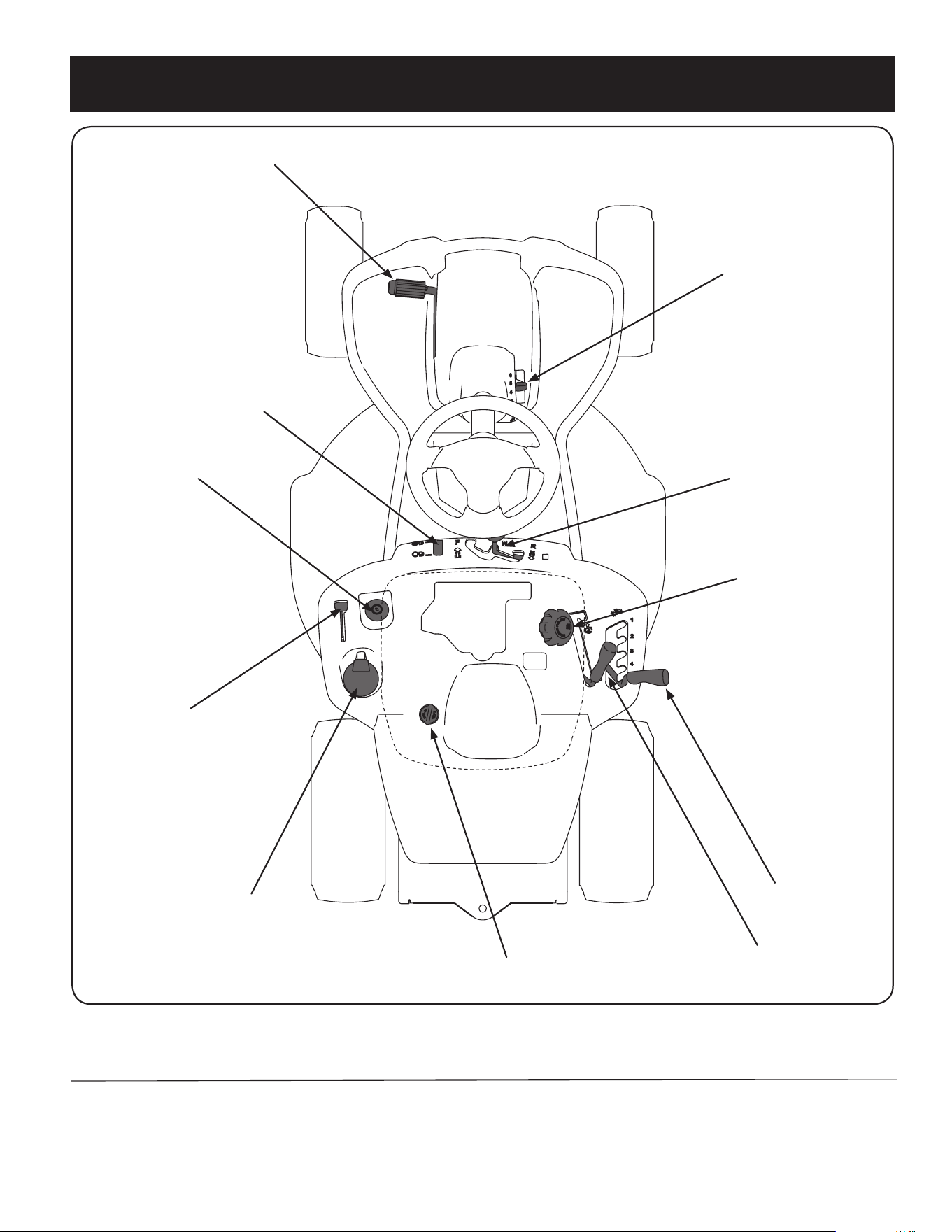
OPERATION
Clutch/Brake Pedal
Speed Control & Parking
Brake Lever
Shift Lever
Cup Holder
Throttle/Choke Lever
Ignition Switch
Deck Lift Lever
PTO (Blade Engage) Lever
Oil Fill Cap
Fuel Fill Cap
Fuel Level Indicator
Figure 17
NOTE: Any reference in this manual to the RIGHT or LEFT side of the tractor is observed from operator’s seat position facing forward towards the front of tractor.
Meets ANSI Safety Standards
Craftsman Tractors conform to the safety standard of the American National Standards Institute (ANSI).
16
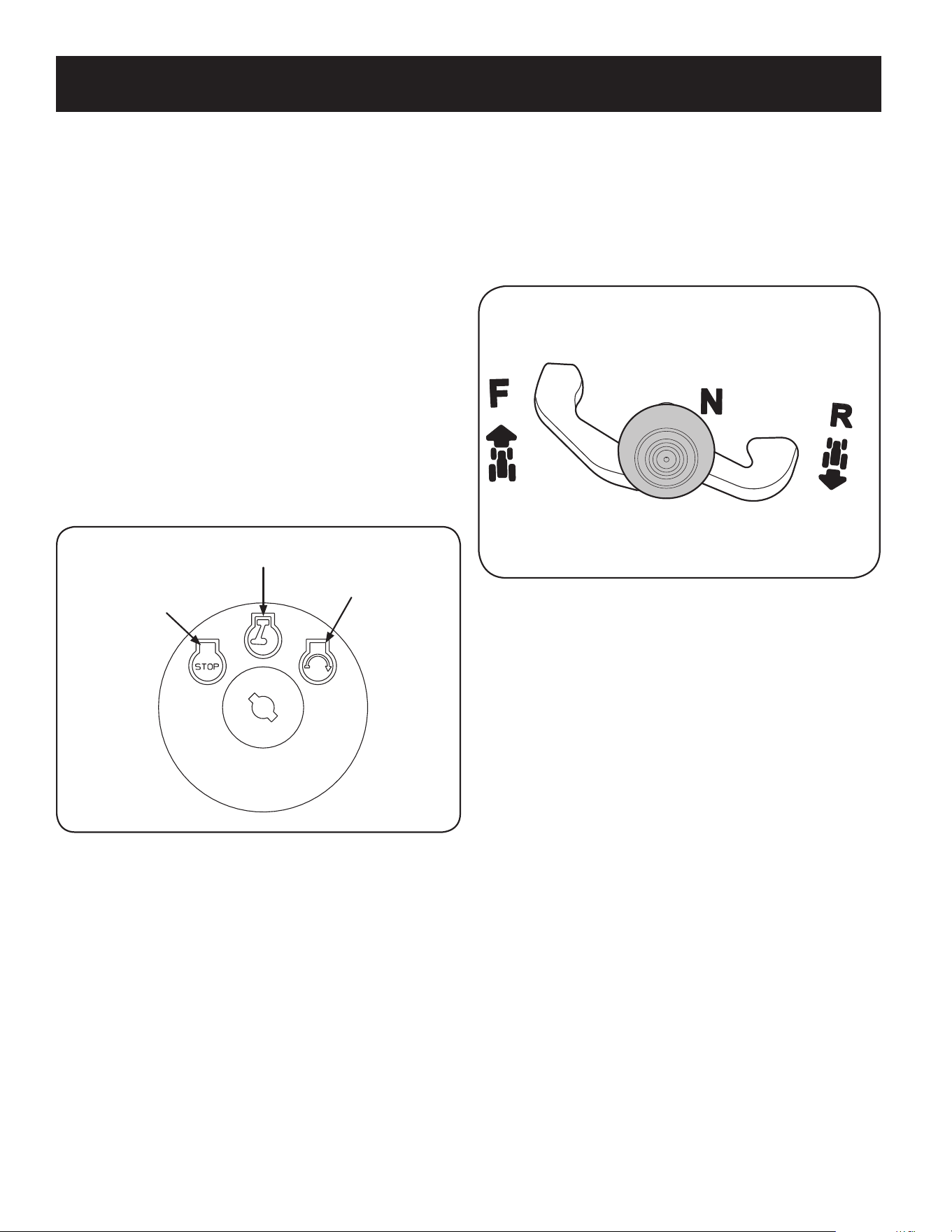
OPERATION
Shift Lever
The shift lever is located on the control panel just below the seat, in the center of
the tractor. It has three positions, FORWARD, NEUTRAL and REVERSE. The brake
pedal must be completely depressed and the tractor must not be in motion
when moving the shift lever. See Figure 19.
IMPORTANT: Never force the shift lever. Doing so may result in serious damage to
the tractor’s transmission.
Figure 19
Speed Control Lever
The speed control lever, located on the right side of the tractor’s steering console,
allows you to regulate the ground speed of the lawn tractor.
To use, depress the clutch-brake pedal and move the lever out of the parking brake
notch and forward to increase the tractor’s ground speed. When a desired speed has
been reached, release the lever into an appropriate notch to maintain that speed.
To slow the tractor’s ground speed, depress the clutch-brake pedal and move the
speed control lever rearward and release it into a notch.
Parking Brake
To set the parking brake, fully depress the clutch-brake pedal. Move the speed
control lever all the way down and into the parking brake position. Release the
clutch-brake pedal to allow the parking brake to engage.
To release the parking brake, depress the clutch-brake pedal and move the speed
control lever out of the parking brake position into the desired position. Release the
clutch-brake pedal.
NOTE: The parking brake must be set if the operator leaves the seat with the engine
running or the engine will automatically shut off.
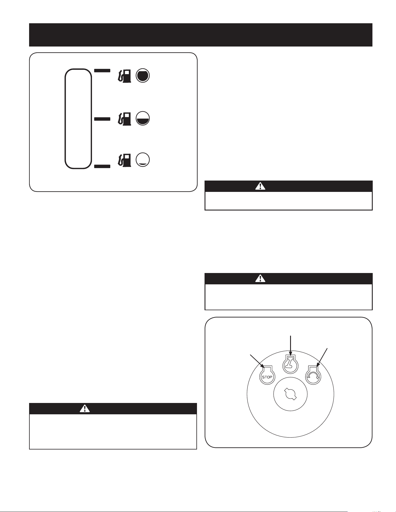
Fuel Lever Indicator
The Fuel Lever Indicator is located below the seat on the left hand side from the
operator’s position in the control panel. Use this window to identify the tractor’s
fuel needs. See Figure 20.
Throttle / Choke Control
The throttle control lever is located on the left fender of the tractor as seen from the
operator’s position, see Figure 17. This lever controls the speed of the engine, as well
as the choke when it is pushed all the way forward. When set in a given position,
the throttle will maintain a uniform engine speed.
IMPORTANT: When operating the tractor with the cutting deck engaged, be certain
that the throttle lever is always in the FAST (rabbit) position.
Moving the throttle lever all the way forward activates the engine’s choke control.
Activating the choke control closes the choke plate on the carburetor and aids in
starting the engine.
Refer to Starting The Engine in the Operation section of this manual for detailed
starting instructions.
Ignition Switch
The ignition switch is located on the left fender of the tractor as seen from the
operator’s position, adjacent to the Throttle/Choke Control. Activate the Ignition
Switch to start the engine by inserting the key into the ignition switch and turn
clockwise to the START position. Release the key into the ON position once engine
has fired. See Figure 18.
Off
On
Start
Figure 18
Clutch-Brake Pedal
The clutch-brake pedal is located on the left side of the lawn tractor, along the
running board. Depress the clutch-brake pedal part way down when slowing the
tractor by changing speeds (Refer to Speed Control Lever). Depress the pedal all the
way down to engage the disc brake and bring the tractor to a complete stop.
NOTE: The clutch-brake pedal must be completely depressed to start the engine.
Refer to Safety Interlock Switches in the Operation section of this manual.
17
OPERATION
Figure 20
Deck Lift Lever
Found on your tractor’s right fender, the deck lift lever is used to change the height
of the cutting deck. To use, move the lever to the left, then place in the notch best
suited for your application.
PTO (Blade Engage) Lever
Found on the tractor’s right fender, the PTO (blade engage) lever is used to engage
power to the cutting deck. To operate, move the lever all the way forward. Moving
the lever all the way rearward into the PTO OFF position disengages power to the
cutting deck.
NOTE: The PTO (blade engage) lever must be in the disengaged (PTO OFF) position
when starting the engine.
Fuel Fill Cap
The Fuel Fill Cap is located below the seat. Refer to the Assembly section in this
manual for instructions on fueling this tractor.
Oil Fill Cap
The Oil Fill Cap is located below the seat. Refer to the Assembly section in this
manual for instructions on checking and adding oil to this tractor.
Fuel Fill Cap
The gasoline tank is located under the seat. Do not overfill.
WARNING
Use extreme care when handling gasoline. Gasoline is extremely flammable
and the vapors are explosive. Never fuel machine indoors or while the
engine is hot or running. Extinguish cigarettes, cigars, pipes, and other
sources of ignition.
For detailed information on adding fuel, refer to Fuel Requirements in the Assembly
section of this manual.
Safety Interlock Switches
The safety interlock system is designed for safe operation of the tractor. If this
system should ever malfunction, do not operate the tractor.
Immediately contact 1-888-331-4569 to have the system serviced.
• The safety interlock system prevents the engine from starting unless
the parking brake is engaged and the PTO (Blade Engage) lever is in the
disengaged (OFF) position.
• The safety interlock system will automatically shut off the engine if the
operator leaves the seat before engaging the parking brake.
• The safety interlock system will automatically shut off the engine if the
operator leaves the tractor’s seat with the PTO (Blade Engage) lever engaged,
regardless of whether the parking brake is engaged.
• The engine will automatically shut off if the PTO (Blade Engage)lever is
moved into the engaged (ON) position with the shift lever in Reverse.
WARNING
Do not operate the tractor if the interlock system is malfunctioning. This
system was designed for your safety and protection.
Ignition Switch
The ignition switch is activated to start the engine. Insert key into the ignition
switch and turn clockwise to the START position. Release the key into the ON
position once engine has fired. See Figure 21.
To stop the engine, turn the ignition key counterclockwise to the OFF position. See
Figure 21.
WARNING
Never leave a running machine unattended. Always disengage PTO, move
shift lever into neutral position, set parking brake, stop engine and remove
key to prevent unintended starting.
Off
On
Start
Figure 21

18
OPERATION
WARNING
Avoid Serious Injury or Death
• Know location and function of all controls.
• Remove objects which could be thrown by the blades.
• Go up and down slopes, not across.
• Use extra caution on slopes. Do not mow slopes greater than 12 degrees.
Avoid sudden turns. Use low speed.
• Do not operate machine where it could tip or slip.
• If machine stops going uphill, stop blades and back down slowly.
• Before leaving operator’s position, disengage blades, engage parking
brake, shut off and remove key.
• Be sure blades and engine are stopped before placing hands or feet near
blades.
• Keep safety devices (guards, shields, switches, etc.) in place and working.
• Keep bystanders away.
• Allow machine to cool before fueling or storing.
• Keep machine free of debris.
Read Operator’s Manual
Engaging the Parking Brake
To engage the parking brake:
1. Fully depress the brake pedal and hold it down with your foot.
2. Move the parking brake lever down into the parking brake position.
3. Release the brake pedal to allow the parking brake to engage.
To release the parking brake:
1. Depress the brake pedal and move the speed control lever out of the parking
brake position.
Setting the Cutting Height
Select the height position of the cutting deck by placing the deck lift lever in any of
the different cutting height notches on the right side of the fender.
WARNING
Keep hands and feet away from the discharge opening of the cutting deck.
Starting the Engine
WARNING
Do not operate the tractor if the interlock system is malfunctioning. This
system was designed for your safety and protection.
NOTE: Refer to the Assembly section of this manual for gasoline and oil fill-up
instructions.
1. Insert the tractor key into the ignition switch.
2. Place the PTO (Blade Engage) lever in the disengaged (OFF) position.
3. Engage the tractor’s parking brake.
4. Activate the choke control.
5. Turn the ignition key clockwise to the START position. After the engine starts,
release the key. It will return to the ON position.
WARNING
IMPORTANT: Do NOT hold the key in the START position for longer than ten
seconds at a time. Doing so may cause damage to your engine’s electric
starter.
6. After the engine starts, deactivate the choke control by placing the throttle
control into the FAST position.
NOTE: Do NOT leave the choke control on while operating the tractor. Doing so will
result in a “rich” fuel mixture and cause the engine to run poorly.
Stopping the Engine
WARNING
If you strike a foreign object, stop the engine, disconnect the spark plug
wire(s) and ground against the engine. Thoroughly inspect the machine for
any damage. Repair the damage before restarting and operating.
1. If the blades are engaged, place the PTO (Blade Engage) lever in the
disengaged (OFF) position.
2. Turn the ignition key counterclockwise to the STOP position.
3. Remove the key from the ignition switch to prevent unintended starting.

19
OPERATION
5. Depress clutch-brake pedal.
6. Place speed control lever in desired position.
7. Place shift lever in either FORWARD or REVERSE, and follow normal operating
procedures.
Driving On Slopes
Refer to the SLOPE GAUGE in the Safety Instructions section of the manual to help
determine slopes where you may operate this tractor safely.
WARNING
Do not mow on inclines with a slope in excess of 12 degrees (a rise of
approximately 2 feet every 10 feet). The tractor could overturn and cause
serious injury.
• Mow up and down slopes, NEVER across.
• Exercise extreme caution when changing direction on slopes.
• Watch for holes, ruts, bumps, rocks, or other hidden objects. Uneven terrain
could overturn the machine. Tall grass can hide obstacles.
• Avoid turns when driving on a slope. If a turn must be made, turn down the
slope. Turning up a slope greatly increases the chance of a roll over.
• Avoid stopping when driving up a slope. If it is necessary to stop while
driving up a slope, start up smoothly and carefully to reduce the possibility
of flipping the tractor over backward.
Driving The Tractor
WARNING
Avoid sudden starts, excessive speed and sudden stops.
WARNING
Do not leave the seat of the tractor without first placing the PTO (Blade
Engage) lever in the disengaged (OFF) position, depressing the brake pedal
and engaging the parking brake. If leaving the tractor unattended, also
turn the ignition key off and remove the key.
WARNING
Always look down and behind before and while backing up to avoid a back-
over accident.
1. Depress the brake pedal and move the speed control lever out of the parking
brake position,then let the pedal release.
2. Move the throttle lever into the FAST (rabbit) position.
3. Place the shift lever in either the FORWARD or REVERSE position.
IMPORTANT: Do NOT use the shift lever to change the direction of travel when the
tractor is in motion. Always use the brake pedal to bring the tractor to a complete
stop before shifting.
4. Release the parking brake by depressing the clutch-brake pedal and
positioning the speed control lever in desired position.
IMPORTANT: First-time operators should use speed positions 1 or 2. Become
completely familiar with the tractor’s operation and controls before operating the
tractor in higher speed positions.
5. Release clutch-brake pedal slowly to put unit into motion.
6. The lawn tractor is brought to a stop by depressing the clutch-brake pedal.
NOTE: When operating the unit initially, there will be little difference between the
highest two speeds until after the belts have seated themselves into the pulleys
during the break-in period.
WARNING
Before leaving the operator’s position for any reason, disengage the blades, place
the shift lever in neutral, engage the parking brake, shut engine off and remove
the key.
IMPORTANT: When stopping the tractor for any reason while on a grass surface,
always:
1. Place the shift lever in neutral,
2. Engage the parking brake,
3. Shut engine off and remove the key. Doing so will minimize the possibility
of having your lawn ‘‘browned’’ by hot exhaust from your tractor’s running
engine.
If unit stalls with speed control in high speed, or if unit will not operate with speed
control lever in a low speed position, proceed as follows:
1. Place shift lever in NEUTRAL.
2. Restart engine.
3. Place speed control lever in highest speed position.
4. Release clutch-brake pedal fully.

20
OPERATION
Mowing
WARNING
To help avoid blade contact or a thrown object injury, keep bystanders,
helpers, children and pets at least 75 feet from the machine while it is in
operation. Stop machine if anyone enters the area.
The following information will be helpful when using the cutting deck with your
tractor:
WARNING
Plan your mowing pattern to avoid discharge of materials toward roads,
sidewalks, bystanders and the like. Also, avoid discharging material against
a wall or obstruction which may cause discharged material to ricochet back
toward the operator.
• Do not mow at high ground speed, especially if a mulch kit or grass collector
is installed.
• For best results it is recommended that the first two laps be cut with the
discharge thrown towards the center. After the first two laps, reverse the
direction to throw the discharge to the outside for the balance of cutting.
This will give a better appearance to the lawn.
• Do not cut the grass too short. Short grass invites weed growth and yellows
quickly in dry weather.
• Mowing should always be done with the engine at full throttle.
• Under heavier conditions it may be necessary to go back over the cut area a
second time to get a clean cut.
• Do NOT attempt to mow heavy brush and weeds and extremely tall grass.
Your tractor is designed to mow lawns, NOT clear brush.
• Keep the blade sharp and replace the blade when worn. Refer to Cutting
Blade in the Maintenance section of this manual for proper blade sharpening
instructions.
• The lamps turn OFF when the ignition key is moved to the STOP position.
Engaging the Blades
Engaging the PTO (Blade Engage) transfers power to the cutting deck. To engage
the blades, proceed as follows:
1. Move the throttle/choke control lever to the FAST (rabbit) position.
2. Grasp the PTO (Blade Engage) lever and pivot it all the way forward into the
engaged (ON) position.
3. Keep the throttle lever in the FAST (rabbit) position for the most efficient use
of the cutting deck.
NOTE: The engine will automatically shut off if the PTO (Blade Engage) lever is
moved into the engaged (ON) position with the shift lever in Reverse.
Mulching
A mulch kit is available as an attachment. Mulching is a process of recirculating
grass clippings repeatedly beneath the cutting deck. The ultra-fine clippings are
then forced back into the lawn where they act as a natural fertilizer. Contact the
nearest Parts & Repair Service Center to purchase a mulch kit for this unit.
To locate the nearest Parts & Repair Service Center, contact 1-888-331-4569.
Using the Deck Lift Lever
To raise the cutting deck, move the deck lift lever to the left, then place it in the
notch best suited for your application. Refer to Setting The Cutting Height earlier in
this section.

21
SERVICE AND MAINTENANCE
WARNING
Before performing any type of maintenance/service, disengage all controls
and stop the engine. Wait until all moving parts have come to a complete
stop. Disconnect spark plug wire and ground it against the engine to prevent
unintended starting. Always wear safety glasses during operation or while
performing any adjustments or repairs.
Follow the maintenance schedule given below. This chart describes service
guidelines only. Use the Service Log column to keep track of completed
maintenance tasks.
To locate the nearest Parts & Repair Service Center or to schedule service,
simply call 1-888-331-4569.
MAINTENANCE SCHEDULE
Interval Item Service Service Log
Each Use 1. Engine Intake Screens & Cooling
Fans *
2. Exhaust Manifold, Muffler Pipe &
Muffler Shields *
3. Hood/Dash Panel Louvers *
4. Top & Underside of Deck, Under
and Around Spindle Covers &
Belt Area *
5. Around Fuses, Wiring and Wiring
Harnesses *
6. Around Transmission, Axle and Fans *
7. Engine Oil
8. Air Filter
1. Check/Clean
2. Check/Clean
3. Check/Clean
4. Check/Clean
5. Check/Clean
6. Check/Clean
7. Check
8. Check
In the First Five Hours 1. Engine Oil 1. Change
Every 10 Hours 1. Hood/ Dash air vents
2. Battery terminals
3. Deck spindle and idler bracket
1. Clean
2. Clean
3. Lubricate
Every 25 hours 1. Air filter’s precleaner*
2. Air filter*
3. Mid-steering arms, pivot shafts,
rack and axles
4. Front wheel bearings
1. Clean
2. Clean
3. Lubricate
4. Lubricate
Every 50 hours 1. Engine oil/ Oil filter
2. Muffler
1. Change/Replace
2. Check
Annually 1. Air filter
2. Air filter’s pre-cleaner
3. Spark plug
4. Air cooling system*
5. Fuel filter
6. Steering Gears
7. Rear Wheels
1. Replace
2. Replace
3. Replace
4. Clean
5. Replace
6. Clean
7. Remove and grease axles
Before Storage 1. Hood/ Dash air vents
2. Battery terminals
3. Mid steering arms, pivot shafts,
and axles
4. Front wheel bearings
5. Deck spindle and idler bracket
6. Pedal pivot points
1. Clean
2. Clean
3. Lubricate
4. Lubricate
5. Lubricate
6. Lubricate
* -- Perform more often in dry conditions and/or when mulching
WARNING
Before performing any maintenance or repairs, disengage the PTO (Blade
Engage Lever), engage the parking brake, stop the engine and remove the
key to prevent unintended starting.
WARNING
If the engine has been recently run, the engine, muffler and surrounding
metal surfaces will be hot and can cause burns to the skin. Exercise caution
to avoid burns.
22
SERVICE AND MAINTENANCE
7. Move the rider’s PTO into the engaged (ON) position.
8. Remain in the operator’s position with the deck engaged for a minimum of
two minutes, allowing the underside of the deck to thoroughly rinse.
9. Move the rider’s PTO into the disengaged (OFF) position.
10. Turn the ignition key to the STOP position to turn the rider’s engine off.
11. Turn the water off and detach the hose coupler from the water port on your deck’s
surface.
12. After cleaning your deck with the Smart Jet system, return to the operator’s
position and engage the PTO. Keep the deck running for a minimum of two
minutes, allowing the underside of the deck to thoroughly dry.
Cleaning the Rider
WARNING
If the rider has been recently run, the engine, muffler and surrounding
metal surfaces will be hot and can cause burns to the skin. Let the engine
cool for at least five minutes Exercise caution to avoid burns.
Your rider should be cleaned after each use and under certain conditions, i.e. dry
conditions and/or mulching situations, additional cleaning may be necessary.
One of the best ways to keep your rider running efficiently and to reduce fire risk
is to regularly remove debris buildup from the rider. Follow the recommendations
below and contact your authorized dealer with any questions.
• Allow the machine to cool in an open area before cleaning.
• Do not use water on any part of the rider except the underside of the cutting
deck. Doing so can cause damage to the rider’s spindle bearings, electrical
system and engine, leading to premature failures. The use of compressed air
and/or leaf blower will help keep the rider clean.
• Clean under the hood. Exhaust manifold, around fuses, all wiring and
harnesses, muffler pipe, muffler shield, engine intake screens and cooling
fins, etc. See “Figure 2”.
Figure 2
Post-Operation Rider Care
After each operation of the rider, the following procedures should be implemented
to extend the life of your rider and ensure safe operating conditions.
DANGER
Failure to follow these recommendations may result in serious injury to
yourself or others and may cause damage to the rider.
Cleaning the Underside of the Deck
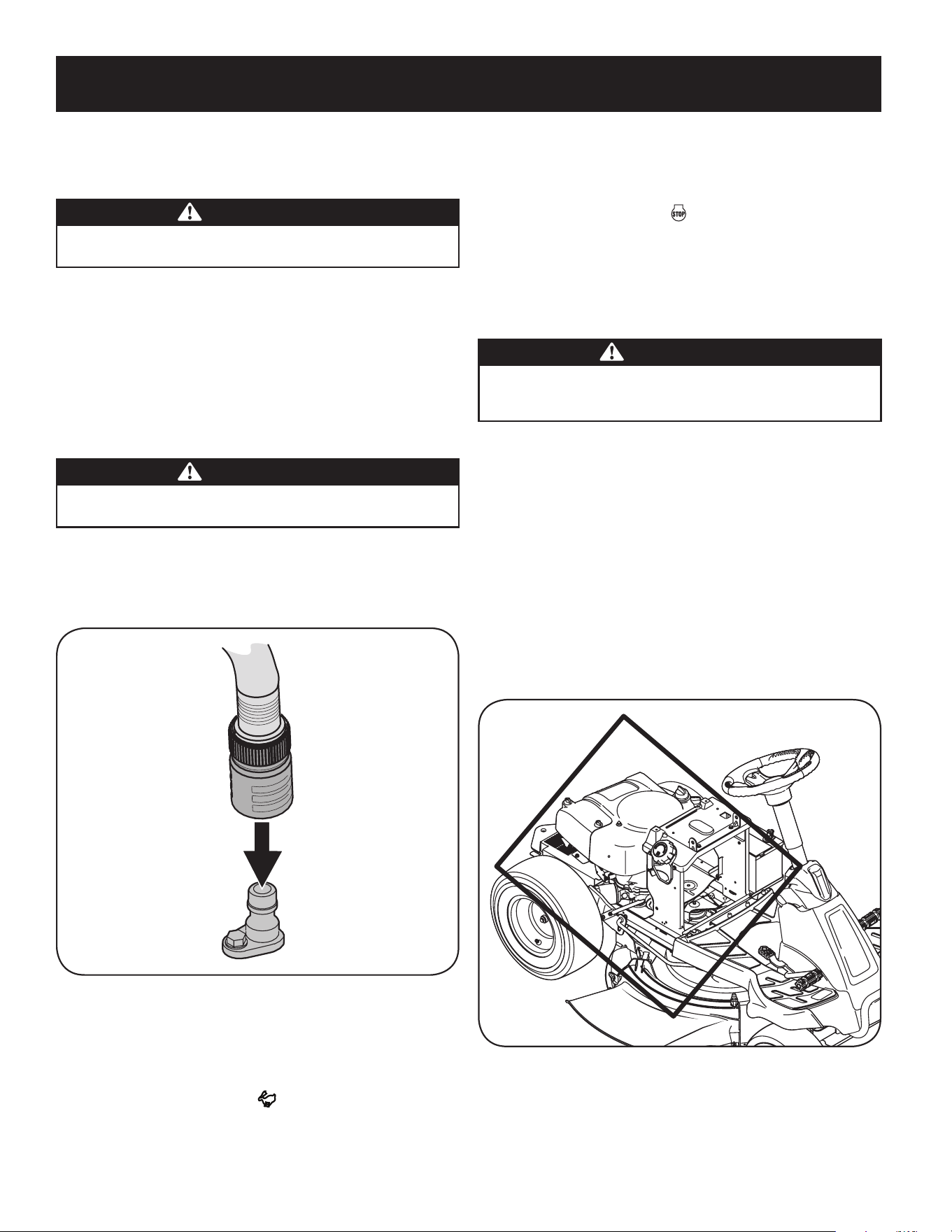
Deck Wash System (if equipped)
Your rider’s deck is equipped with a water port on its surface as part of its deck wash
system.
Use the deck wash system to rinse grass clippings from the deck’s underside and
prevent the buildup of corrosive chemicals. Complete the following steps AFTER
EACH MOWING:
1. Drive the rider to a level, clear spot on your lawn, near enough for your
garden hose to reach.
WARNING
Make certain the rider’s discharge chute is directed AWAY from people, your
house, garage, parked cars, etc.
2. Disengage the PTO, set the parking brake and stop the engine.
3. Thread the hose coupler (packaged with your rider’s Operator’s Manual) onto
the end of your garden hose.
4. Attach the hose coupler to the water port on your decks surface. See “Figure 1”.
Figure 1
Note: Make sure that the hose is not routed under the deck and is clear of all
moving parts.
5. Turn the water on.
6. While sitting in the operator’s position on the rider, start the engine and
place the throttle lever in the FAST position.
23
SERVICE AND MAINTENANCE
Storing the Rider
• Allow the machine to cool in an open area before storing.
• Do not park the rider near any flammable materials (wood, cloth or
chemicals) or any open flames or other potential source of ignition (furnace,
water heater or any other type of heater).
• Remove all combustible materials from the rider before storing. Empty cargo
boxes, grass catchers or containers.
• Always shut off fuel flow when storing or transporting if rider is equipped
with a fuel shutoff.
• Check the fuel system (lines, tank, cap and fittings) frequently for cracks or
leaks. Repair and clean as necessary.
Engine Maintenance
WARNING
Shut off the engine before performing any maintenance. To prevent
accidental start-up, disconnect the spark plug boot.
IMPORTANT: If engine must be tipped to transport equipment or to inspect or
remove grass, keep spark plug side of engine up. Transporting or tipping engine
spark plug down may cause smoking, hard starting, spark plug fouling, or oil
saturation of air cleaner.
Periodic inspection and adjustment of the engine is essential if high level
performance is to be maintained. Regular maintenance will also ensure a long
service life. The required service intervals and the kind of maintenance to be
performed are described in the table on the previous page. Follow the hourly or
calendar intervals, whichever occur first. More frequent service is required when
operating in adverse conditions.
WARNING
If the engine has been running, the muffler will be very hot. Be careful not
to touch the muffler.
Servicing the Engine Oil
• Check the oil level regularly.
• Be sure correct oil level is maintained. Check the oil every five to ten hours of
operation, before starting the engine. See Checking Oil Level in the Assembly section.
Only use high quality detergent oil rated with API service classification SF, SG,
SH, or SJ. Select the oil’s SAE viscosity grade according to the expected operating
temperature. Refer to Gas & Oil in the Assembly section of this manual.
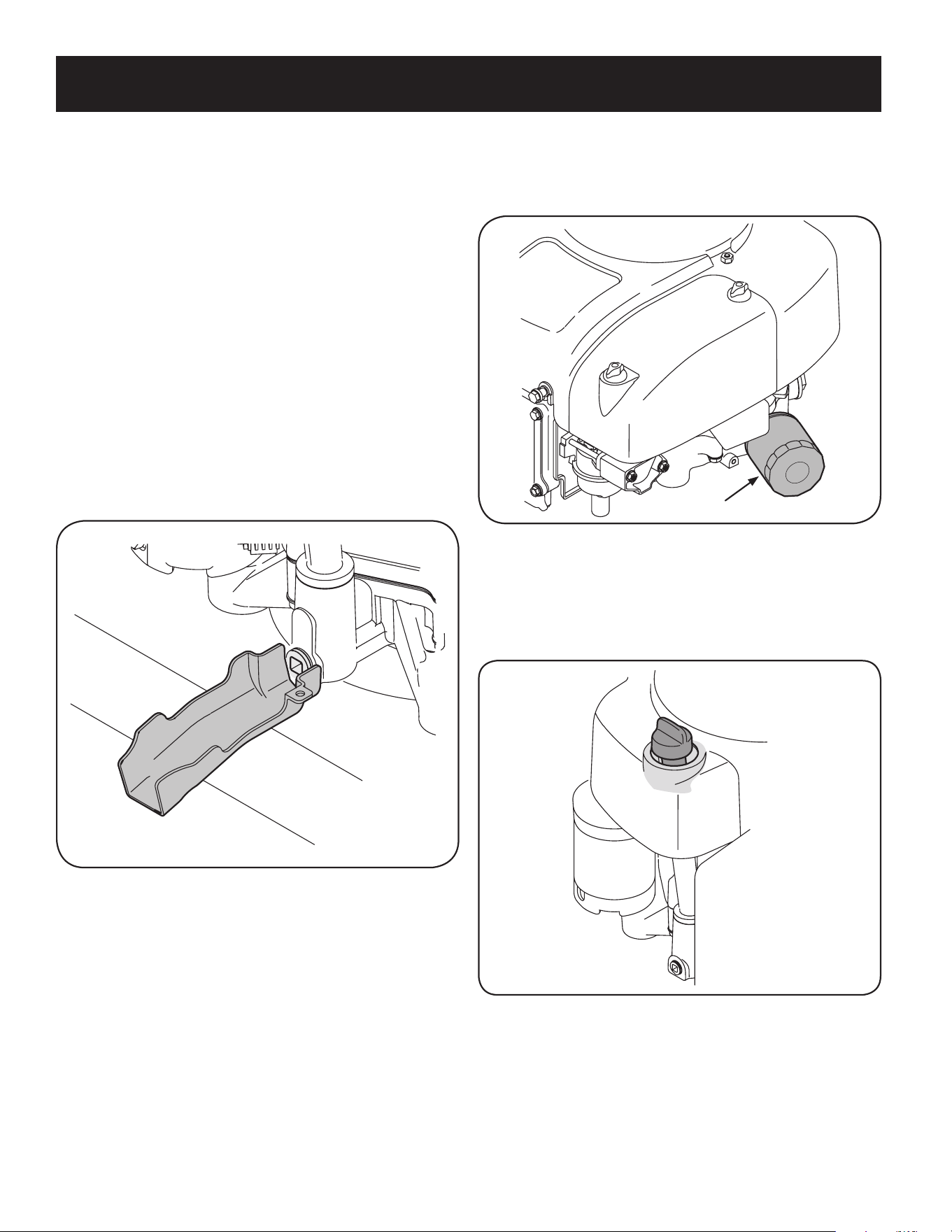
Oil Drain
IMPORTANT: Be sure to check engine on a level surface with the engine stopped.
Drain the oil while the engine is still warm to assure rapid and complete draining.
For draining oil from the engine’s crankcase of select model tractors, a plastic oil drain
sleeve is packed with this Operator’s Manual. To drain the oil, proceed as follows:
13. Unscrew the oil fill cap and remove the dipstick from the oil fill tube.
14. Snap the small end of oil drain sleeve onto the oil sump. See “Figure 4”.
15. Remove drain plug and drain oil into a suitable container with a capacity of
no less than 64 oz.
16. Tip the tractor slightly in the direction of the suitable container to aid in fully
draining all of the oil from the engine.
WARNING
Before tipping engine or equipment to drain oil, drain fuel from tank by
running engine until fuel tank is empty.
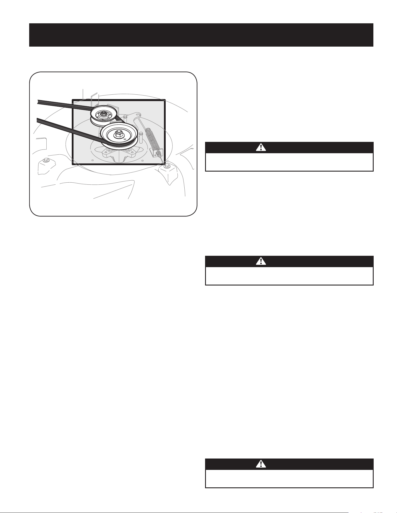
• Clean the top of the mower deck, under the spindle covers and belt area. See
“Figure 3”.
Figure 3
• Clean around and near the transmission, axle and the fan area. See “Figure
3”.
• Debris can accumulate anywhere on the rider, especially on horizontal
surfaces. Additional cleaning may be necessary when mowing in dry
conditions or when mulching.
• Fuel leaks/spills, oil leaks/spills and excess lubrication can also become
collections sites for debris. Immediate repair and cleaning up oil or fuel spills
can help reduce fire hazards.
• In addition to cleaning the rider before operating and storing, do not
attempt to mow unusually tall grass (10” or higher), dry grass (e.g., pasture)
or piles of dry leaves. Dry grass or leaves may contact the engine exhaust
and/or build up on the mower deck presenting a potential fire hazard.
Battery
Clean the battery by removing it from the riding mower and washing with a
baking soda and water solution. If necessary, scrape the battery terminals with a
wire brush to remove deposits. Coat terminals and exposed wiring with grease or
petroleum jelly to prevent corrosion.
The battery is sealed and is maintenance-free. Acid levels cannot be checked.
• Always keep the battery cables and terminals clean and free of corrosive
build-up.
• After cleaning the battery and terminals, apply a light coat of petroleum jelly
or grease to both terminals.
• Always keep the rubber boot positioned over the positive terminal to prevent
shorting.
Important: If removing the battery for any reason, disconnect the NEGATIVE
(Black) wire from it’s terminal first, followed by the POSITIVE (Red) wire.
When re-installing the battery, always connect the POSITIVE (Red) wire its
terminal first, followed by the NEGATIVE (Black) wire. Be certain that the
wires are connected to the correct terminals; reversing them could change
the polarity and result in damage to your engine’s alternating system.
24
SERVICE AND MAINTENANCE
6. Make sure dipstick is installed.
7. Start and run engine. Check for leaks.
8. Stop engine. Wait a few minutes and check the oil level. See Checking The
Oil Level in the Assembly section of this manual.
Oil Filter
Figure 5
Adding Oil
IMPORTANT: Be sure to check engine on a level surface with the engine stopped.
1. Wipe around dipstick cap and tube with a clean cloth to remove any debris.
See “Figure 6”.
Figure 6
2. Remove dipstick and wipe clean with a cloth.
3. Pour oil into the dipstick tube. Do not over fill. With an oil filter change the
high level amount of oil for this engine is 1700 ml (57.48 fl-oz.).
4. Install dipstick and turn to locked position before starting engine.
5. Start engine. Allow to run for a few seconds and then shut down the engine.
6. Check the oil level. See Checking Oil Level in the Assembly section of this
manual.
17. Service the Oil Filter if desired, as per the instructions later in this section.
18. Reinstall the drain plug and tighten it securely, 12-14 Nm (106.2-123.9 in-lb).
19. Remove the oil drain sleeve from the oil sump. Return the dipstick to the oil fill
tube and screw the oil fill cap back into place.
20. Pour oil into the dipstick tube. Do not over fill. With an oil filter change the high
level amount of oil for this engine is 1700 ml (57.48 fl-oz.).
21. Install dipstick and turn to locked position before starting engine.
22. Start the engine. Allow it to run for a few seconds and then shut down the
engine.
23. Check the oil level.
IMPORTANT: Used motor oil may cause skin cancer if repeatedly left in contact with
the skin for prolonged periods. Although this is unlikely unless you handle used oil
on a daily basis, it is still advisable to thoroughly wash your hands with soap and
water as soon as possible after handling used oil.
NOTE: Please dispose of used motor oil in a manner that is compatible with the
environment. We suggest you take it in a sealed container to your local service
station for reclamation. Do not throw it in the trash, pour it down a drain or on the
ground.
Figure 4
Replacing The Oil Filter
This engine is equipped with a spin-on oil filter that should be replaced each time
an oil change is performed, every season or 50 hours. Refer to “Figure 5”.
To replace the Oil Filter:
1. Drain the oil as instruction previously in this section.
2. Remove the oil filter. Dispose of the old oil filter properly.
3. Lube gasket of new oil filter with clean oil.
4. Install and turn oil filter by hand until the gasket comes in contact with the
sealing surface of the crankcase cover, then tighten the oil filter, 10-12 Nm
(88.5-106.2 in-lb), 1/2-3/4 turn.
5. Add oil as previously instructed.

25
SERVICE AND MAINTENANCE
2. Remove thumb screw (A). See Figure 8.
A
B
Figure 8
3. Pull up and remove air filter and base seal (B). See Figure 8.
4. Remove the foam pre-filter from around the paper air filter. See “Figure
9”. Replace paper element when dirty or damaged. Clean foam element or
replace when damaged.
Air Filter
Pre-Filter
Figure 9
5. To clean foam element, wash in a mild liquid detergent and water. Squeeze
or press the foam element to rinse out dirt and water. Do not twist; this
could damage or tear the foam element. Allow to dry thoroughly before
using. DO NOT oil the foam element.
Air Filter Service
Paper filters cannot be cleaned and should be replaced every 100 operating hours;
more often if used in extremely dusty conditions.
WARNING
Never use gasoline or low flash point solvents for cleaning the air filter
element. A fire or explosion could result.
CAUTION
Do not use pressurized air or solvents to clean the air cleaner
cartridge.
WARNING
If filters, or covers are not installed correctly serious injury or death
could result from backfire. Do not attempt to start the engine with them
removed.
IMPORTANT: Never run the engine without the air filter. Rapid engine wear will
result.
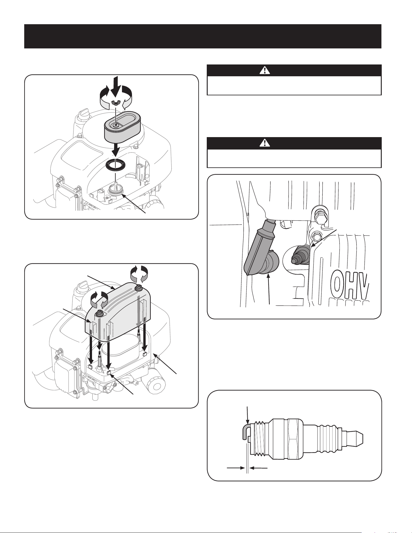
1. Unscrew the thumb screws and remove the air filter cover. See “Figure 7”.
Air Filter Cover
Thumb Screw
Figure 7
26
SERVICE AND MAINTENANCE
Spark Plug Service
WARNING
DO NOT check for spark with spark plug removed. DO NOT crank engine with
spark plug removed.
To ensure proper engine operation, the spark plug must be properly gapped and
free of deposits.
1. Remove the spark plug boot and use a spark plug wrench to remove the
plug. See “Figure 12”.
WARNING
If the engine has been running, the muffler will be very hot. Be careful not
to touch the muffler.
Spark Plug
Spark Plug Boot
Figure 12
2. Visually inspect the spark plug. Discard the spark plug if there is apparent
wear, or if the insulator is cracked or chipped. Clean the spark plug with a
wire brush if it is to be reused.
3. Measure the plug gap with a feeler gauge. Correct as necessary by
bending side electrode. See “Figure 13”. The gap should be set to between
0.024-0.031 in.
Electrode
0.024-0.031 in.
Figure 13
4. Check that the spark plug washer is in good condition and thread the spark
plug in by hand to prevent cross-threading.
6. Attach the new air filter with foam element, aligning the hole in the air filter
with the intake manifold. See “Figure 10”. Secure with thumb screw.
Intake Manifold
Figure 10
7. Attach the air filter cover, making sure to align plastic rib features on the
shroud to the plastic features on the air filter cover. See “Figure 11”. Turn
thumb screws clockwise until snug. Check for any misalignment.
Plastic Rib
Feature
Shroud
Plastic
Feature
Air Filter
Cover
Figure 11
27
SERVICE AND MAINTENANCE
5. After the spark plug is seated, tighten with a spark plug wrench to compress
the washer.
NOTE: When installing a new spark plug, tighten 1/2 turn after the spark
plug seats to compress the washer. When reinstalling a used spark plug,
tighten 1/8-1/4 turn after the spark plug seats to compress the washer.
IMPORTANT: The spark plug must be securely tightened. An improperly
tightened spark plug can become very hot and may damage the engine.
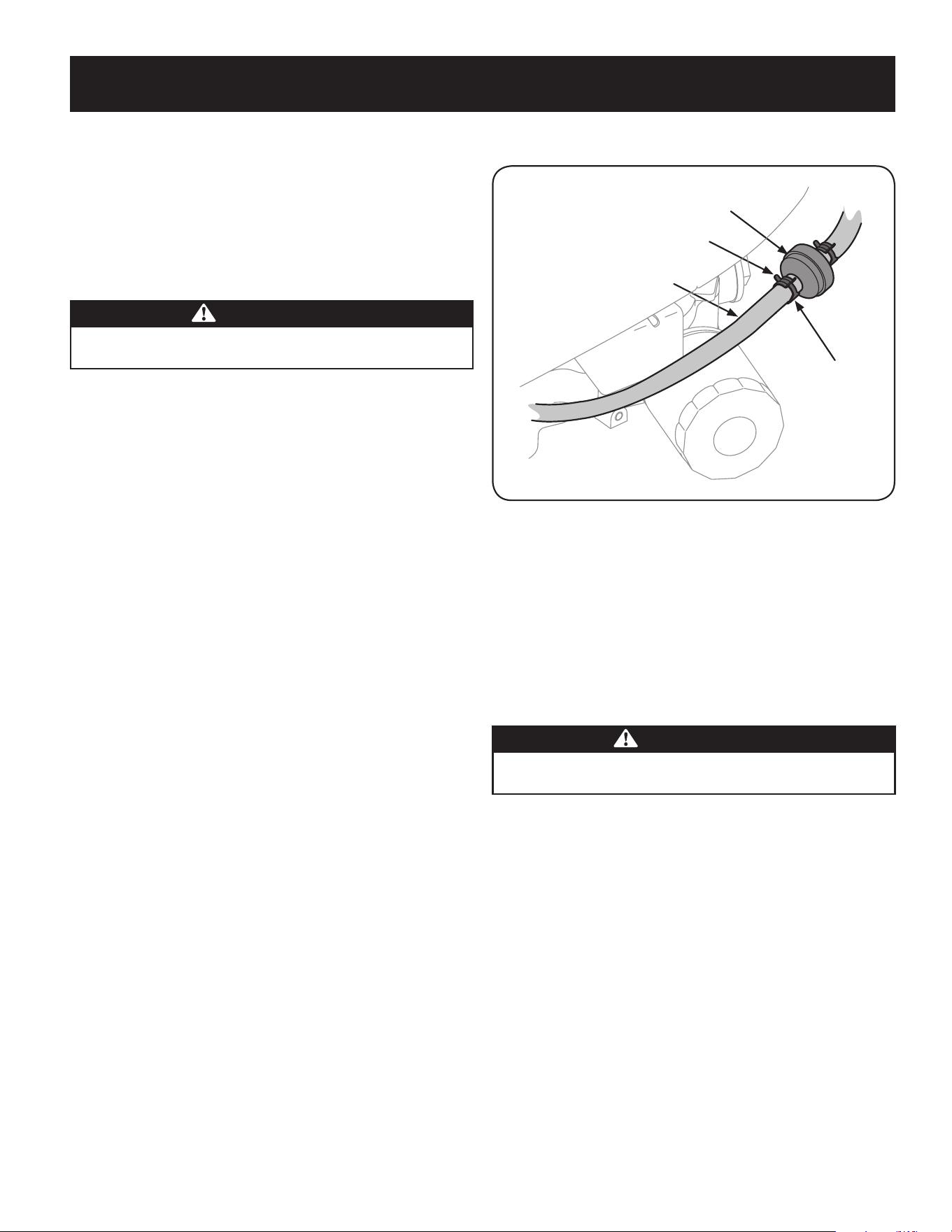
Fuel Filter Service
WARNING
Gasoline and its vapors are extremely flammable and explosive. Fire or
explosion can cause severe burns or death.
• Keep gasoline away from sparks, open flames, pilot lights, heat, and other
ignition sources.
• Check fuel lines, tank, cap, and fittings frequently for cracks or leaks. Replace
if necessary.
• Before replacing the fuel filter, drain the fuel tank as in To Drain the Fuel.
• Do not drain fuel when the engine is hot. Allow the engine adequate time to
cool. Drain fuel into an approved container outdoors, away from open flame.
• Drain any large volume of fuel from the tank by disconnecting the fuel line
from the in-line fuel filter near the engine.
• Remove the fuel line from the ln-line side (side towards the fuel tank) of the
fuel filter.
• Replacement parts must be the same and installed in the same position as
the original parts.
• If fuel spills, wait until it evaporates before starting engine.
• Before replacing the fuel filter, drain the fuel tank. Otherwise, fuel can leak
out and cause a fire or explosion.
To Drain The Fuel:
1. Locate the fuel filter, which is routed on the left side of the engine between
the fuel tank and the carburetor, and may be attached to the engine with a tie
strap. Cut the tie strap, if present, then pinch the in-line clamp on the fuel filter
with a pair of pliers, slide the clamp up the fuel line. Pull the fuel line free from
the filter and place the open end of the line into an approved container to drain
the fuel.
To Change The Fuel Filter:
1. Use pliers to squeeze the tabs on the other clamp (the out-line side of the
fuel filter), and slide the clamp away from the fuel filter. Twist and pull the
fuel line off of the fuel filter. See “Figure 14”.
2. Check the fuel lines for cracks or leaks. Replace if necessary.
3. Replace the fuel filter with an original equipment replacement filter. Call
1-888-331-4569 to purchase the original equipment replacement
filter.
4. Secure the fuel lines with the clamps.
The fuel filter cannot be cleaned and should be replaced every 100 operating hours;
more often if run with old gasoline.
Fuel Filter
Fuel Line
Tab
Clamp
Figure 14
Clean Engine
If the engine has been running, allow it to cool for at least half an hour before
cleaning. Periodically remove dirt build-up from engine. Clean the engine cooling
fins every 25 hours. Clean with a brush or compressed air.
IMPORTANT: Do not spray engine with water to clean because water could
contaminate fuel. Using a garden hose or pressure washing equipment can also
force water into the air cleaner or muffler opening. Water in the air cleaner will soak
the paper element, and water that passes through the element or muffler can enter
the cylinder, causing damage.
WARNING
Accumulation of debris around muffler could cause a fire. Inspect and clean
before every use.
Cutting Deck Removal
To remove the cutting deck, proceed as follows:
1. Place the PTO (Blade Engage) lever in the disengaged (OFF) position and
engage the parking brake.
2. Lower the deck by moving the deck lift lever into the bottom notch on the
right fender.

28
SERVICE AND MAINTENANCE
5. Remove the remaining bow-tie cotter pins securing the deck to the unit, as
shown in “Figure 17”.
Figure 17
NOTE: The bow-tie clips should be re-installed from the top down.
6. Move the deck lift lever into the top notch on the right fender to raise the
deck lift arms up and out of the way.
7. Unplug the wiring pigtail from the deck safety switch.
8. Carefully remove the PTO cable from the rear of the cutting deck by
removing the bow-tie cotter pin which secures it. Remove the spring from
the deck idler bracket. See “Figure 18”.
Figure 18
9. Gently slide the cutting deck (from the left side) out from underneath the
tractor.
Changing the Deck Belt
NOTE: It is possible to change the deck belt with the cutting deck still installed on
the tractor, however it is much easier to remove the deck first, change the deck belt,
then reinstall the cutting deck.
To change the cutting deck belt, proceed as follows:
3. Remove the belt from around the tractor’s PTO pulley. See “Figure 15”.
WARNING
Avoid pinching injuries. Never place your fingers on the idler spring or
between the belt and a pulley while removing the belt.
Figure 15
4. Remove the bow-tie cotter pin and flat washer from the deck lift assembly,
and retain for reinstallation later. See “Figure 16”.
Figure 16
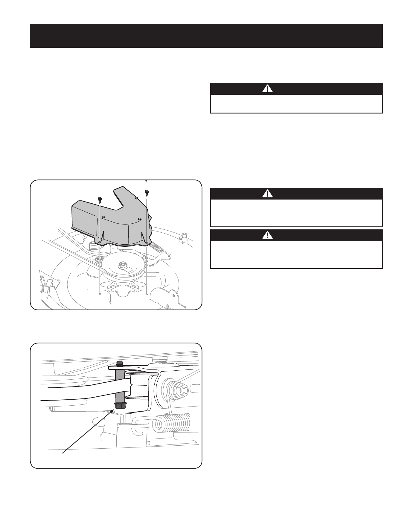
29
SERVICE AND MAINTENANCE
1. It is easiest to change the deck belt by first removing the cutting deck as
instructed earlier in this section. Skip this step if deciding to change the deck
belt with the mowing deck still installed on the unit. Otherwise, remove the
cutting deck now.
2. If changing the deck belt with the cutting deck still installed on the unit,
lower the cutting deck to the lowest cutting position.
3. Remove the deck belt from around the unit’s PTO drive pulley as shown in
“Figure 15”. Simply roll one side of the belt off of the pulley and then work
it off the pulley by continuing around the pulley until the belt is off of the
pulley.
4. Pull the belt towards the front of the unit, pulling it through and out of the
belt keeper bracket, shown in “Figure 15”.
5. Remove the deck belt cover by removing the three hex bolts that secure it.
See “Figure 19”.
Figure 19
6. Remove the belt keeping spacer by removing the hex bolt that secures it. See
“Figure 20”.
Belt Keeper Hex bolt
Figure 20
7. Change the belt, then reinstall the all the components removed in the
reverse order beginning with the idler pulley, and lastly the belt cover.
8. Feed the deck belt through the belt keeper bracket and work it around and
onto the PTO drive pulley as shown in “Figure 15”.
Tires
WARNING
Never exceed the maximum inflation pressure shown on the sidewall of tire.
The recommended operating tire pressure is:
• Approximately 10 psi for the rear tires
• Approximately 14 psi for the front tires
IMPORTANT: Refer to the tire sidewall for exact tire manufacturer’s recommended
or maximum psi. Do not overinflate. Uneven tire pressure could cause the cutting
deck to mow unevenly.
Cutting Blade
WARNING
Shut the engine off and remove ignition key before removing the cutting
blade for sharpening or replacement. Protect your hands by using heavy
gloves when grasping the blade.
WARNING
Periodically inspect the blade and/or spindle for cracks or damage,
especially after you’ve struck a foreign object. Do not operate the machine
until damaged components are replaced.
To remove the blade, proceed as follows.
NOTE: It may be easier to change the blade by first removing the deck from
beneath the tractor, (refer to Cutting Deck Removal earlier in this section)
then gently flip the deck over to expose its underside. It is possible to change
the blade, however, with the deck still attached to the tractor. If attempting
to change the blade with the deck still installed on the tractor, first move the
deck lift lever to its highest cutting position.
1. Remove the mulch plug, deck chute or bagging chute, if equipped, exposing
the deck chute opening.
2. Using a block of wood or 2 x 4, insert it into the deck opening and rotate the
blade around until it wedges the wood between the deck opening and the
cutting blade, as shown in “Figure 21”.
3. Remove the hex flange nut that secures the blade to the spindle assembly,
and remove the blade. See the Inset of “Figure 21”.
NOTE: The deck spindle has a normal thread. To loosen, rotate the flange lock
nut counterclockwise.

30
SERVICE AND MAINTENANCE
Figure 21
4. To properly sharpen the cutting blades, remove equal amounts of metal
from both ends of the blades along the cutting edges, parallel to the trailing
edge, at a 25°- to 30° angle. Always grind each cutting blade edge equally to
maintain proper blade balance. See “Figure 22”.
Figure 22
CAUTION
If the cutting edge of the blade has previously been sharpened, or if any
metal separation is present, replace the blades with new ones.
WARNING
A poorly balanced blade will cause excessive vibration, may cause damage to
the tractor and/or result in personal injury.
5. Test the blade’s balance using a blade balancer. Grind metal from the
heavy side until it balances evenly.
NOTE: When replacing the blade, be sure to install the blade with the side of
the blade marked ‘‘Bottom’’ (or with a part number stamped in it) facing the
ground when the mower is in the operating position.
CAUTION
Use a torque wrench to tighten the blade spindle hex flange nut to between
70 lbs-ft and 90 lbs-ft.
Adjustments
WARNING
Never attempt to make any adjustments while the engine is running, except
where specified in the operator’s manual.
Leveling the Deck
NOTE: Check the tractor’s tire pressure before performing any deck leveling
adjustments. Refer to Tires, in this Service And Maintenance section for more
information regarding tire pressure.
Front To Rear
It is possible to adjust the pitch of the cutting deck. The front of the deck should be
between 0” (level) and ¼” lower than the rear of the deck. Adjust if necessary as
follows:
1. With the tractor parked on a firm, level surface, place the lever for lifting the
cutting deck into the middle position (3) and rotate the blade so that it is
aligned with the front and rear of the tractor.
2. Measure the distance from the front of the blade tip to the ground and the
rear of the blade tip to the ground. The first measurement taken should be
between 0” (level) and ¼” less than the second measurement. Determine
the approximate distance necessary for proper adjustment and proceed, if
necessary, to the next step.
3. Locate the flange lock nut on the front end of the PTO Lift Rod. See “Figure
23”.
• Tighten the flange lock nut to raise the front of the deck;
• Loosen the flange lock nut to lower the front of the deck.
Figure 23
Seat Adjustment
Refer to the Assembly section of this manual for seat adjustment instructions.
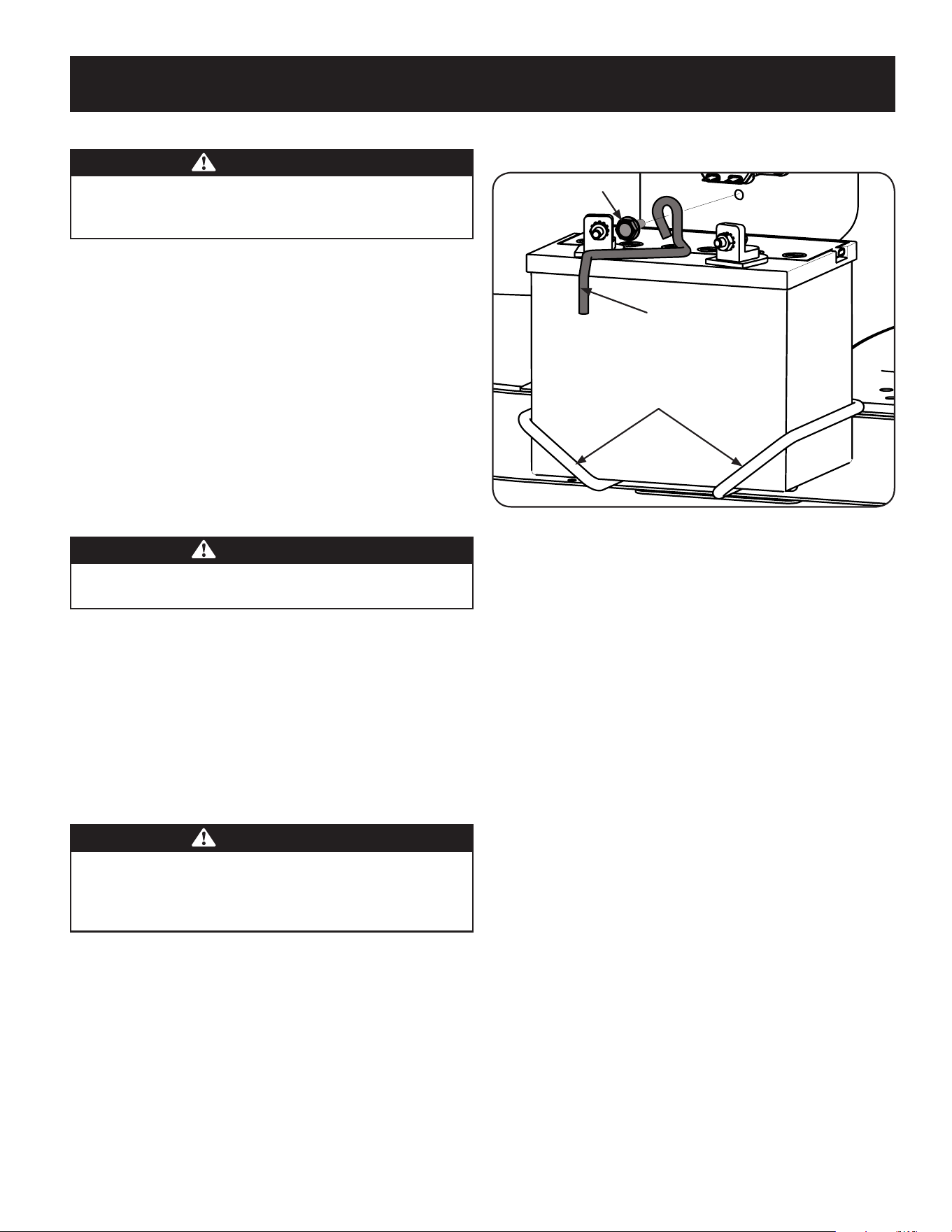
31
SERVICE AND MAINTENANCE
Parking Brake Adjustment
WARNING
Never attempt to adjust the brakes while the engine is running. Always
disengage PTO (Blade Engage Lever), move shift lever into neutral position,
stop engine and remove key to prevent unintended starting.
If the tractor does not come to a complete stop when the clutch-brake pedal is
completely depressed, or if the tractor’s rear wheels can roll with the parking brake
applied, the brake is in need of adjustment. Contact the nearest Parts & Repair
Service Center to have your brakes serviced.
To locate the nearest Parts & Repair Service Center or to schedule service,
contact 1-888-331-4569.
Changing the Transmission Drive Belt
NOTE: Several components must be removed and special tools (i.e. air/impact
wrench) in order to change the tractor’s drive belt. Contact the nearest Parts &
Repair Service Center to have your transmission drive belt serviced.
To locate the nearest Parts & Repair Service Center or to schedule service, call
1-888-331-4569.
Muffler
WARNING
Temperature of muffler and nearby engine areas may exceed 150˚ F (65˚C).
Avoid contact with these areas.
• Inspect muffler periodically, and replace if necessary. Replacement parts
for the muffler must be the same and installed in the same position as the
original parts.
Carburetor Adjustment
• The carburetor on this engine is not adjustable.
Battery
California Proposition 65 WARNING! Battery posts, terminals, and related
accessories contain lead and lead compounds, chemicals known to the State of
California to cause cancer and reproductive harm. Wash hands after handling.
CAUTION
If removing the battery, disconnect the NEGATIVE (Black) wire from its
terminal first, followed by the POSITIVE (Red) wire. When re-installing
the battery, always connect the POSITIVE (Red) wire to its terminal first,
followed by the NEGATIVE (Black) wire.
The battery is sealed and is maintenance-free. Acid levels cannot be checked.
• Always keep the battery cables and terminals clean and free of
corrosive build-up.
• After cleaning the battery and terminals, apply a light coat of
petroleum jelly or grease to both terminals.
• Always keep the rubber boot positioned over the positive terminal to
prevent shorting.
Removing the Battery
1. Locate the battery on the left side of the riding mower.
2. Remove the hex washer screw securing the battery hold-down rod to the
frame. See “Figure 24”.
Hex Washer Screw
Battery Hold-Down Rod
Battery Tray
Figure 24
3. With the battery hold-down rod removed, lift the battery out of the battery
tray.
4. To re-install the battery, place it back in the battery tray and secure in place
with the battery hold-down rod and hex washer screw. See “Figure 24”.
IMPORTANT: If removing the battery for any reason, disconnect the NEGATIVE
(Black) wire from its terminal first, followed by the POSITIVE (Red) wire. When
re-installing the battery, always connect the POSITIVE (Red) wire to its terminal
first, followed by the NEGATIVE (Black) wire. Be certain that the wires are connected
to the correct terminals; reversing them could change the polarity and result in
damage to your engine’s alternating system.
Cleaning Battery
Clean the battery by removing it from the tractor and washing with a baking soda
and water solution. If necessary, scrape the battery terminals with a wire brush to
remove deposits. Coat terminals and exposed wiring with grease or petroleum jelly
to prevent corrosion.
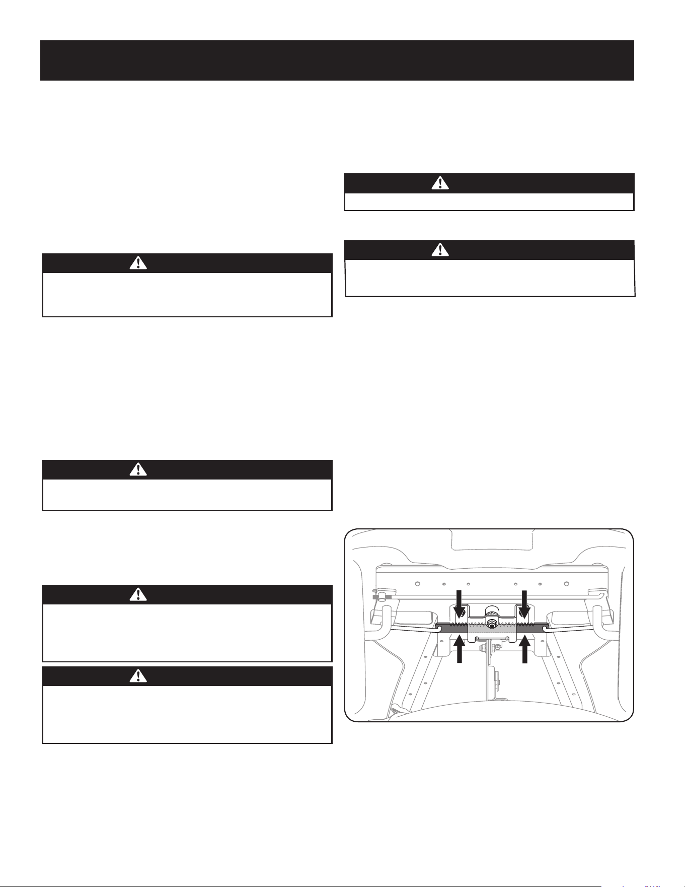
32
SERVICE AND MAINTENANCE
Battery Failures
Some common causes for battery failure are:
• Incorrect initial activation
• Overcharging
• Freezing
• Undercharging
• Corroded connections
These failures are NOT covered by your tractor’s warranty.
Jump Starting
WARNING
Never jump start a damaged or frozen battery. Be certain the vehicles
do not touch, and ignitions are off. Do not allow cable clamps to
touch.
1. Connect positive (+) cable to positive post (+) of your tractor’s discharged
battery.
2. Connect the other end of the cable to the positive (+) post of the jumper
battery.
3. Connect the second cable negative (–) to the negative post (–) of the jumper
battery.
4. Connect the other end of the negative cable to the engine block of the
tractor, away from the battery. Attach to an unpainted part to assure a good
connection.
WARNING
If the jumper battery is installed on a vehicle (i.e. car, truck), do NOT start
the vehicle’s engine when jump starting your tractor.
5. Start the tractor (as instructed in the Operation section of this manual).
6. Set the tractor’s parking brake before removing the jumper cables, in reverse
order of connection.
Charging
WARNING
Batteries give off an explosive gas while charging. Charge the battery in
a well ventilated area and keep away from an open flame or pilot light
as on a water heater, space heater, furnace, clothes dryer or other gas
appliances.
CAUTION
When charging your tractor’s battery, use only a charger designed for 12V
lead-acid batteries. Read your battery charger’s Owner’s Manual prior to
charging your tractor’s battery. Always follow its instructions and heed its
warnings.
If your tractor has not been put into use for an extended period of time, charge the
battery as follows:
1. Set your battery charger to deliver a max of 10 amperes.
If your battery charger is automatic, charge the battery until the charger indicates
that charging is complete. If the charger is not automatic, charge for no fewer than
eight hours.
Fuse
One 15 AMP fuse is installed in your tractor’s wiring harness to protect the tractor’s
electrical system from damage caused by excessive amperage.
If the electrical system does not function, or your tractor’s engine will not crank;
first check to be certain that the fuse has not blown. It can be found under the
fender on the left side of the unit, on the wiring harness just above the battery.
WARNING
Always use a fuse with the same amperage capacity for replacement.
Lubrication
WARNING
Before lubricating, repairing, or inspecting, always disengage PTO (Blade
Engage Lever), move shift lever into neutral position, set parking brake, stop
engine and remove key to prevent unintended starting.
Pivot Points & Linkage
Lubricate all the pivot points on the drive system, parking brake and lift linkage at
least once a season with light oil.
Rear Wheels
The rear wheels should be removed from the axles once a season. Lubricate the
axles and the rims well with an all-purpose grease before re-installing them.
Front Axles
Each end of the tractor’s front pivot bar may be equipped with a grease fitting.
Lubricate with a grease gun after every 25 hours of tractor operation.
Steering Rack & Pinion
Once per season, or every 25 hours of operation, it will be necessary to lubricate the
steering rack and pinion gear located under the front of the unit. Using standard
automotive grease, apply grease to the front side and rear side of the steering rack,
as indicated in “Figure 25”.
Figure 25

33
OFF-SEASON STORAGE
WARNING
Gasoline is a toxic substance. Dispose of gasoline properly. Contact
your local authorities for approved disposal methods.
3. Remove the spark plug and pour one (1) ounce of engine oil
through the spark plug hole into the cylinder. Crank the engine
several times to distribute the oil. Replace the spark plug.
4. Clean debris from around engine, under finger guard, and under,
around and behind muffler. Touch up any damaged paint, and
coat other areas that may rust with a light film of oil.
5. Store in a clean, dry and well ventilated area away from any ap-
pliance that operates with a flame or pilot light, such as a furnace,
water heater, or clothes dryer. Also avoid any area with a spark
producing electric motor, or where power tools are operated.
6. If possible, also avoid storage areas with high humidity, because
that promotes rust and corrosion.
7. Keep the engine level in storage. Tilting can cause fuel or oil
leakage.
DRAINING THE FUEL
1. Locate the fuel filter, which is located on the left side of the
engine, and may be attached to the engine with a tie strap.
2. Cut the tie strap, if present, then pinch the in-line clamp on the
fuel filter with a pair of pliers, slide the clamp up the fuel line.
3. Pull the fuel line free from the filter and place the open end of the
line into an approved container to drain the fuel.
PREPARING THE LAWN TRACTOR
1. Clean and lubricate the unit thoroughly as described in the
Lubrication instructions in the Service and Maintenance section.
2. Do not use a pressure washer or garden hose to clean your unit.
3. Store mower in a dry, clean area. Do not store next to corrosive
materials, such as fertilizer.
Removing From Storage
1. Check the oil level as described in the Assembly section of this
manual.
2. If the fuel was drained during storage preparation, fill the tank with
fresh gasoline. If you keep a container of gasoline for refueling,
make certain it contains only fresh fuel. Gasoline oxidizes and
deteriorates over time, causing hard starting.
3. If the cylinder was coated with oil during storage preparation, the
engine will smoke briefly at startup. This is normal.
WARNING
Never store lawn tractor with fuel in tank indoors or in poorly
ventilated areas where fuel fumes may reach an open flame, spark,
or pilot light as on a furnace, water heater, clothes dryer, or gas
appliance.
PREPARING THE ENGINE
IMPORTANT: Fuel left in the fuel tank during warm weather deterio-
rates and will cause serious starting problems.
CAUTION
Failure to use a fuel stabilizing additive or completely run the engine
until it’s out of fuel before off-season storage may result in damage to
your engine’s carburetor. Subsequent damage would not be covered
under the manufacturer’s warranty.
Engines stored between 30 and 90 days need to be treated with a
gasoline stabilizer and engines stored over 90 days need to be drained
of fuel to prevent deterioration and gum from forming in fuel system or
on essential carburetor parts. If the gasoline in your engine deterio-
rates during storage, you may need to have the carburetor, and other
fuel system components, serviced or replaced.
To prevent gum deposits from forming inside the engine’s carburetor
and causing possible malfunction of the engine, the fuel system must
be either completely emptied, or the gasoline must be treated with a
stabilizer to prevent deterioration.
1. If using a fuel stabilizer:
a. Read the product manufacturer’s instructions and recom-
mendations.
b. Add to clean, fresh gasoline the correct amount of stabilizer
for the capacity of the fuel system.
c. Fill the fuel tank with treated fuel and run the engine for 2-3
minutes to get stabilized fuel into the carburetor.
2. If emptying the fuel system:
a. Do not drain fuel when the engine is hot. Allow the engine
adequate time to cool. Drain fuel into an approved container
outdoors, away from open flame.
b. Drain any large volume of fuel from the tank by disconnect-
ing the fuel line from the in-line fuel filter near the engine.
See the complete instructions for Draining The Fuel later in
this section.
WARNING
Gasoline is extremely flammable and can be explosive under certain
conditions. Drain gasoline before storing the equipment for extended
periods. Drain fuel only into an approved container outdoors, away
from an open flame. Allow engine to cool. Extinguish cigarettes,
cigars, pipes, and other sources of ignition prior to draining fuel.
Store gasoline in an approved container in safe location.
c. Reconnect the fuel line and run the engine until it starts to
falter, then use the choke to keep the engine running until all
fuel in the carburetor has been exhausted.
d. Disconnect the fuel line and drain any remaining gasoline
from the system.

34
TROUBLESHOOTING
Problem Cause Remedy
Engine fails to start 1. PTO/Blade Engage lever engaged.
2. Parking brake not engaged.
3. Spark plug wire(s) disconnected.
4. Throttle/Choke control lever not in correct
starting position.
5. Choke not activated
6. Fuel tank empty, or stale fuel.
7. Blocked fuel line.
8. Faulty spark plug(s).
9. Engine flooded.
10. Blown Fuse(s).
11. Safety switch(s) not properly engaged.
1. Place lever in disengaged (OFF) position.
2. Engage parking brake.
3. Connect wire(s) to spark plug(s).
4. Place Throttle/Choke lever into the FAST position.
5. Move the Throttle/Choke lever into the Choke
position.
6. Fill tank with clean, fresh (less than 30 days old) gas.
7. Replace the fuel line and replace fuel filter.
8. Clean, adjust gap or replace plug(s).
9. Crank engine with throttle in FAST position.
10. Replace Fuse(s)
11. Ensure seat is in the proper operating position, and/
or deck chute, tube or mulch plug properly installed.
Engine runs erratically 1. Unit running with CHOKE activated.
2. Spark plug wire(s) loose.
3. Blocked fuel line or stale fuel.
4. Vent in gas cap plugged.
5. Water or dirt in fuel system.
6. Dirty air cleaner.
1. Deactivate the CHOKE.
2. Connect spark plug wire(s).
3. Replace the fuel line; fill tank with clean, fresh
gasoline and replace fuel filter.
4. Clear vent or replace cap if damaged.
5. Drain fuel tank. Refill with clean, fresh gasoline.
6. Replace air cleaner paper element or clean foam
pre-cleaner, if equipped.
Engine overheats 1. Engine oil level low.
2. Air flow restricted.
1. Fill crankcase with proper amount and weight of oil.
2. Clean grass clippings and debris from around the
engine’s cooling fins and housing.
Engine hesitates at high RPM 1. Spark plug gap too close. 1. Remove spark plug and reset the gap.
Engine idles rough 1. Spark plug fouled, faulty or gap too wide.
2. Dirty air cleaner.
1. Replace spark plug. Set plug gap.
2. Replace air cleaner element and/or clean pre-
cleaner.
Excessive vibration 1. Cutting blade loose or unbalanced.
2. Damaged or bent cutting blade.
1. Tighten blade and spindle.
2. Replace blade.
Mower will not mulch grass 1. Engine speed too low.
2. Wet grass.
3. Excessively high grass.
4. Dull blade.
1. Place throttle in FAST (rabbit) position.
2. Do not mulch when grass is wet.
3. Mow once at a high cutting height, then mow again
at desired height or make a narrower cutting swath.
4. Sharpen or replace blade.
Uneven cut 1. Deck not leveled properly.
2. Dull blade.
3. Uneven tire pressure.
1. Perform side-to-side deck adjustment.
2. Sharpen or replace blade.
3. Check tire pressure in all four tires.

35
Notes Page
This page intentionally left blank. Use this page to make any notes regarding your tractor.

36
ÍNDICE
NÚMERO DE MODELOESPECIFICACIONES DEL PRODUCTO
Medidas de seguridad .........................Página 34
Montaje ......................................Página 40
Operación ....................................Página 44
Servicio y Mantenimiento .....................Página 50
Almacenamiento fuera de temporada .........Página 62
Solución de problemas ........................Página 63
Declaración de garantía ..............Vea el suplemento
seperado
Motor: Consulte el manual del motor
Aceite del motor: Consulte el manual del motor
Capacidad del aceite: Consulte el manual del motor
Combustible: Gasolina sin plomo
Número de modelo _____________________________
Número de serie ________________________________
Fecha de compra _______________________________
Registre el número de modelo, número de serie y fecha
de compra más arriba.
ADVERTENCIA
Antes de usar este equipo, lea el manual y siga todas las medidas de seguridad e instrucciones de funcionamiento.
NOTA: Este manual del operador cubre varios modelos. Las características pueden variar según el modelo. No todas las funciones de este manual son aplicables a todos los
modelos y el modelo que se muestra puede diferir del suyo.

37
INSTRUCCIONES DE SEGURIDAD
FUNCIONAMIENTO GENERAL
• Lea, entienda y cumpla todas las instrucciones incluidas en la máquina y en
los manuales antes de montarla y utilizarla. Guarde este manual en un lugar
seguro para consultas futuras y periódicas, así como para solicitar repuestos.
• Familiarícese con todos los controles y con el uso adecuado de los mismos.
Sepa cómo detener la máquina y desactivar los controles rápidamente.
• No permita nunca que los niños menores de 14 años utilicen esta máquina.
Los niños de 14 años en adelante deben leer y entender las instrucciones
de operación y normas de seguridad contenidas en este manual, y en la
máquina y deben ser entrenados y supervisados por un adulto.
• Nunca permita que los adultos operen esta máquina sin recibir antes la
instrucción apropiada.
• Para ayudar a evitar el contacto con las cuchillas o una lesión por algún
objeto que sea arrojado, mantenga a los observadores, a los ayudantes, niños
y mascotas alejados al menos 25 metros de la máquina mientras está en
funcionamiento. Detenga la máquina si alguien entra en la zona.
• Inspeccione minuciosamente el área donde utilizará el equipo. Retire todas
las piedras, palos, cables, huesos, juguetes y otros objetos extraños que
podrían ser recogidos y arrojados por la acción de las cuchillas. Los objetos
arrojados por la máquina pueden producir lesiones graves.
• Planifique el patrón de corte del césped que ha de seguir para evitar la
descarga de material hacia los caminos, las veredas, los observadores, etc.
Evite además descargar material contra las paredes y obstrucciones que
podrían provocar que el material descargado rebote contra el operador.
• Para protegerse los ojos utilice siempre anteojos o antiparras de seguridad
mientras opera la máquina o mientras la ajusta o repara. Los objetos
arrojados que rebotan pueden producir lesiones oculares graves.
• Utilice zapatos de trabajo resistentes, de suela fuerte, así como pantalones
y camisas ajustados. Las prendas sueltas o las alhajas pueden quedar
atrapadas en las piezas movibles. Nunca opere la máquina descalzo o con
sandalias.
• Esté atento a la cortadora y a la dirección de la descarga de los aditamentos
y no apunte a nadie. Nunca opere la cortadora de césped sin que estén en su
lugar apropiado la cubierta de descarga o el colector de recortes de césped.
• No ponga las manos o los pies cerca de las piezas rotatorias o debajo de
la plataforma de corte. El contacto con las cuchillas puede producir la
amputación de manos y pies.
• Una cubierta de descarga faltante o dañada puede provocar el contacto con la
cuchilla o lesiones por objetos arrojados.
• Detenga la(s) cuchilla(s) cuando atraviese senderos, sendas o caminos de grava
y cuando no esté cortando el césped.
• Vigile el tránsito vehicular cuando esté operando cerca de o en cruces de
caminos. Esta máquina no debe utilizarse en la vía pública.
• No opere esta máquina bajo los efectos del alcohol o de drogas.
• Corte el césped solamente con luz de día o con una buena luz artificial.
• Nunca transporte pasajeros.
• Desenganche la(s) cuchilla(s) antes de colocar la marcha atrás. Retroceda
lentamente. Siempre mire hacia abajo y hacia atrás antes y mientras retrocede,
para evitar accidentes.
• Reduzca la velocidad antes de dar la vuelta. Opere la máquina suavemente.
Evite la operación errática y la velocidad excesiva.
ADVERTENCIA
La presencia de este símbolo indica que se trata de instrucciones
importantes de seguridad que se deben respetar para evitar poner en
peligro su seguridad personal y/o material y la de otras personas. Lea y siga
todas las instrucciones de este manual antes de poner en funcionamiento
esta máquina. Si no respeta estas instrucciones podría provocar lesiones
personales. Cuando vea este símbolo, ¡preste atención a la advertencia!
ADVERTENCIA
PROPOSICIÓN 65 DE CALIFORNIA
El escape del motor de este producto, algunos de sus componentes y
algunos componentes del vehículo contienen o liberan sustancias químicas
que el estado de California considera que pueden producir cáncer, defectos
de nacimiento u otros problemas reproductivos. Los bornes de la batería y
los accesorios afines contienen plomo y compuestos de plomo, sustancias
químicas que según lo establecido por el Estado de California causan
cáncer y daños en el sistema reproductivo. Lávese las manos después de
estar en contacto con estos componentes.
PELIGRO
Esta máquina fue construida para ser operada de acuerdo con las reglas
de seguridad contenidas en este manual. Al igual que con cualquier tipo
de equipo motorizado, un descuido o error por parte del operador puede
producir lesiones graves. Esta máquina es capaz de amputar manos y pies
y de arrojar objetos con gran fuerza. De no respetar las instrucciones de
seguridad siguientes se pueden producir lesiones graves o la muerte.
ADVERTENCIA
Su responsabilidad—Restrinja el uso de esta máquina motorizada
a las personas que lean, comprendan y respeten las advertencias e
instrucciones que aparecen en este manual y en la máquina.
¡GUARDE ESTAS INSTRUCCIONES!

38
INSTRUCCIONES DE SEGURIDAD
• Desenganche la(s) cuchilla(s), coloque el freno de estacionamiento, detenga
el motor y espere hasta que la(s) cuchilla(s) se detenga(n) por completo antes
de retirar el colector de césped, vaciar los recortes, destapar el canal, retirar
restos de césped o desechos, o hacer cualquier ajuste.
• Nunca deje la máquina en funcionamiento sin vigilancia. Apague siempre las
cuchillas, coloque el freno de mano, detenga el motor y retire la llave antes
de bajarse del vehículo.
• Tenga sumo cuidado al cargar o descargar la máquina en un remolque o
camión. Esta unidad no debe conducirse en ascenso o descenso de rampas,
porque podría ladearse y provocar lesiones personales graves. En las rampas
la máquina se debe empujar manualmente para cargarla o descargarla
correctamente.
• El silenciador y el motor se calientan y pueden causar quemaduras. No los
toque.
• Revise el espacio libre por encima de la cabeza antes de conducir bajo las
ramas bajas de árboles, cables, cerramientos de puertas, etc. en los cuales el
operador podría atorarse o ser empujado fuera de la máquina, lo que podría
resultar en lesiones graves.
• Desenganche todos los embragues de los accesorios y presione totalmente el
pedal del freno antes de intentar arrancar el motor.
• La máquina está diseñada para cortar césped residencial normal, con una
altura no mayor a 12”. No intente cortar césped demasiado crecido, seco (por
ej., pastura) ni pilas de hojas secas. El césped y las hojas secas pueden entrar
en contacto con el escape del motor y/o acumularse en la plataforma de la
cortadora de césped, convirtiéndose en un peligro de incendio
• Utilice solamente accesorios y aditamentos aprobados para esta máquina
por el fabricante de la misma. Lea, comprenda y siga todas las instrucciones
proporcionadas con los accesorios o aditamentos aprobados. Para obtener
una lista de los accesorios aprobados y los archivos adjuntos, llame 1-888-
331-4569.
• Los datos estadísticos muestran que los operadores de 60 años y mayores se
ven involucrados en un alto porcentaje de lesiones relacionadas con tractores
corta césped. Estos operadores deben evaluar su capacidad para operar el
tractor corta césped en forma suficientemente segura para protegerse a ellos
mismos y a los demás contra lesiones graves.
• Si se presentan situaciones que no están previstas en este manual sea
cuidadoso y use el sentido común.
FUNCIONAMIENTO EN PENDIENTES
Las pendientes son un factor importante relacionado con accidentes por derrape y vuelcos que pueden
producir lesiones graves e incluso la muerte. La operación en pendientes requiere mayor precaución. Si
no puede retroceder en la pendiente o si no se siente seguro, no realice ninguna operación de corte.
Para su seguridad, use el indicador de pendientes que se incluye como parte de este manual para medir
la pendiente antes de operar la máquina en una zona inclinada. Si la pendiente es mayor de 12 grados
según el medidor, no opere esta máquina en ese sector, pues podría causar lesiones graves.
Haga lo siguiente:
• Pode hacia arriba y abajo de las pendientes, no de forma transversal. Tenga
cuidado cuando cambie de dirección al operar en pendiente.
• Esté atento a los hoyos, surcos, baches, rocas, u otros objetos ocultos. El terreno
desnivelado puede voltear la máquina. El césped alto puede ocultar obstáculos.
• Vaya a baja velocidad. Elija una velocidad lo suficientemente baja, de modo
que no tenga que detenerse o hacer cambios mientras está sobre la pendiente.
Los neumáticos podrían perder tracción sobre las pendientes aún cuando los
frenos funcionaran apropiadamente. Siempre mantenga la máquina en cambio
mientras desciende las pendientes, para poder frenar con el motor.
• Siga las recomendaciones del fabricante para los pesos o contrapesos de las
ruedas, para mejorar la estabilidad de la máquina.
• Tenga especial cuidado con los colectores de césped u otros aditamentos. Los
mismos pueden modificar la estabilidad de la máquina.
• Haga que todos los movimientos en las pendientes sean lentos y graduales. No
cambie repentinamente la velocidad ni la dirección. Un frenado o cambio de
velocidad repentinos pueden causar que el frente de la máquina se levante y dé
una voltereta hacia atrás, lo que podría producir lesiones graves.
• Evite arrancar o detenerse en una pendiente. Si los neumáticos pierden la
tracción, desenganche las cuchillas y descienda lentamente la pendiente.
No haga lo siguiente:
• No gire sobre las pendientes a menos que sea necesario. Si es posible, gire
lentamente y gradualmente durante el descenso.
• No corte el césped cerca de pozos, hundimientos o terraplenes. La cortadora
de césped puede volcarse repentinamente si una de las ruedas está sobre el
borde de un acantilado, zanja o si un borde se desmorona.
• No intente estabilizar la máquina poniendo el pie en el suelo.
• No utilice un colector de césped en pendientes empinadas.
• No pode el césped húmedo. Una menor tracción podría causar derrapes.
• No para descender. El exceso de velocidad puede hacer que el operador
pierda el control de la máquina, ocasionando lesiones graves e incluso la
muerte.
• No remolque cargas pesadas detrás de los aditamentos (carrito de basura
cargado, podadora de rodillos, etc) en pendientes mayores de 5 grados.
Cuando se desplaza pendiente abajo, el peso adicional tiende a empujar el
tractor y puede hacer que se pierda el control del mismo (por ejemplo, el
tractor se puede acelerar, se reduce la capacidad para frenar y maniobrar,
los accesorios pueden plegarse como un cortaplumas y hacer que el tractor
vuelque).
NIÑOS
Pueden ocurrir accidentes trágicos si el operador no está atento a la presencia de niños. Por lo general,
los niños se sienten atraídos por este tipo de máquinas y su funcionamiento. No entienden los riesgos ni
los peligros. Nunca asuma que los niños permanecerán en el mismo lugar donde los vio por última vez.
• Mantenga a los niños fuera del área de trabajo y bajo estricta vigilancia de un
adulto responsable además del propio operador.
• Esté alerta y apague la máquina si un niño ingresa al área.
• Antes y mientras está retrocediendo, mire hacia atrás y cuide que no haya
niños.
• Nunca transporte niños, aún con la cuchilla apagada. Podrían caerse y
resultar severamente heridos o interferir con la operación segura de la
máquina.

39
INSTRUCCIONES DE SEGURIDAD
• Tenga extrema precaución cuando se aproxime a esquinas ciegas, portales,
arbustos, árboles u otros objetos que puedan impedirle ver a un niño que se
cruce en el recorrido de la máquina.
• Para evitar accidentes al operar en marcha atrás, siempre desenganche
las cuchillas antes de colocar marcha atrás. Si está instalado, el “Modo
Precaución Marcha Atrás” (hojas de operar la máquina, mientras que los
paseos a la inversa) no debe utilizarse cuando hay niños u otras personas
presentes.
• Mantenga a los niños alejados de los motores en marcha o calientes. Pueden
sufrir quemaduras con un silenciador caliente.
• Retire la llave cuando deje la máquina sin vigilancia, evite que una persona
sin autorización la maneje.
No permita nunca que los niños menores de 14 años utilicen esta máquina. Los niños de 14 años en
adelante deben leer y entender las instrucciones de operación y normas de seguridad contenidas en
este manual, y en la máquina y deben ser entrenados y supervisados por un adulto.
REMOLQUE
• Remolque únicamente con una máquina que cuente con un enganche
diseñado para remolcar. No acople equipo remolcado excepto en el punto de
enganche.
• Siga las recomendaciones del fabricante en lo que respecta a los límites de
peso de los equipos a remolcar y al remolque en pendientes.
• Nunca permita la presencia de niños u otras personas dentro o sobre los
equipos remolcados.
• En las pendientes, el peso del equipo remolcado puede causar pérdida de
tracción y pérdida de control de la máquina.
• Siempre use extra la precaución remolcando con una máquina capaz de
hacer vueltas apretadas (p.ej paseo “de vuelta cero” - en el cortacésped).
Haga amplias vueltas para evitar al gato-knifing.
• Desplácese lentamente y deje distancia adicional para frenado.
• No para descender.
SERVICIO
Manejo Seguro de la Gasolina
Para evitar lesiones personales o daños materiales sea sumamente cuidadoso
al manipular la gasolina. La gasolina es sumamente inflamable y sus vapores
pueden causar explosiones. Se puede lesionar gravemente si derrama
gasolina sobre usted o sobre la ropa, ya que ésta se puede incendiar. Lávese la
piel y cámbiese de ropa de inmediato.
• Utilice sólo los recipientes para gasolina autorizados.
• Nunca llene los recipientes en el interior de un vehículo o camión o caja de
remolque con recubrimiento plástico. Coloque siempre los recipientes en el
piso y lejos del vehículo antes de realizar la carga.
• Cuando sea factible, retire el equipo a gasolina del camión o remolque y
llénelo en el suelo. Si esto no es posible, llene el equipo en un remolque con
un contenedor portátil, en vez de hacerlo con una boquilla dispensadora de
gasolina.
• Mantenga la boquilla de llenado en contacto con el borde del depósito
de combustible o con la abertura del recipiente en todo momento, hasta
terminar la carga. No utilice un dispositivo de boquilla de apertura/cierre.
• Apague todos los cigarrillos, cigarros, pipas y otras fuentes de combustión.
• Nunca cargue combustible en la máquina en un espacio cerrado.
• Nunca saque la tapa del combustible ni agregue combustible mientras el
motor está caliente o en marcha. Deje que el motor se enfríe por lo menos
dos minutos antes de volver a cargar combustible.
• Nunca llene en exceso el depósito de combustible. Llene el tanque no más
de ½ pulgada por debajo de la base del cuello del tapón de carga, para dejar
espacio para la expansión del combustible.
• Vuelva a colocar la tapa de la gasolina y ajústela bien.
• Limpie el combustible que se haya derramado sobre el motor y el equipo.
Traslade la máquina a otra zona. Espere 5 minutos antes de encender el
motor.
• Para reducir el riesgo de incendio, mantenga la máquina limpia de pasto,
hojas y de acumulación de otros residuos. Limpie los derrames de aceite o
combustible y saque todos los residuos embebidos de combustible.
• Nunca guarde la máquina o el recipiente de combustible en un espacio
cerrado donde haya fuego, chispas o luz piloto, como por ejemplo de
calentadores de agua, calefactores de ambientes, hornos, secadores de ropa
u otros aparatos a gas.
• Deje que la máquina se enfríe cinco minutos por lo menos antes de
guardarla.
Servicio General
• Nunca encienda el motor en espacios cerrados o en una zona con poca
ventilación. El escape del motor contiene monóxido de carbono, un gas
inodoro y letal.
• Antes de limpiar, reparar o inspeccionar la máquina, compruebe que la(s)
cuchilla(s) y todas las partes en movimiento se hayan detenido. Desconecte
el cable de la bujía y póngalo haciendo masa contra el motor para evitar que
se encienda accidentalmente.
• Revise periódicamente para asegurarse que las cuchillas se detengan por
completo en aproximadamente cinco (5) segundos después de accionar el
control de desenganche de la(s) cuchilla(s). Si las cuchillas no se detienen
dentro de este lapso de tiempo, su unidad deberá ser reparada por su
distribuidor de servicio autorizado MTD.
• Revise con frecuencia el funcionamiento del sistema de frenos ya que está
sujeto a desgaste por la operación normal. Ajuste y efectúe mantenimiento
según se requiera.
• Revise los pernos de montaje de la(s) cuchilla(s) y del motor a intervalos
frecuentes para verificar que estén bien apretados. Además, inspeccione
visualmente la(s) cuchilla(s) en busca de daños (por ejemplo, desgaste
excesivo, abolladuras, rajaduras, etc.). Reemplace la(s) cuchilla(s)
únicamente con las cuchillas de fabricantes de equipos originales
(O.E.M.) listadas en este manual. El uso de piezas que no cumplen con
las especificaciones del equipo original podría tener como resultado un
rendimiento incorrecto y además poner en riesgo la seguridad.
• Las cuchillas de las podadoras son muy afiladas. Envuelva la cuchilla o utilice
guantes y extreme las precauciones cuando efectúe mantenimiento.
• Mantenga todos los pernos, tuercas y tornillos bien ajustados para asegurarse
de que la máquina se encuentra en condiciones seguras de operación.
40
INSTRUCCIONES DE SEGURIDAD
NO MODIFIQUE EL MOTOR
Para evitar lesiones graves o la muerte, no modifique el motor bajo ninguna
circunstancia. Si cambia la configuración del regulador del motor el motor
puede descontrolarse y operar a velocidades inseguras. Nunca cambie la
configuración de fábrica del regulador del motor.
AVISO REFERIDO A EMISIONES
Los motores que están certificados y cumplen con las regulaciones de
emisiones federales EPA y de California para SORE (Equipos pequeños todo
terreno) están certificados para operar con gasolina común sin plomo y
pueden incluir los siguientes sistemas de control de emisiones: Modificación
de motor (EM) y catalizador de tres vías (TWC) si están equipados de esa
manera.
GUARDACHISPAS
WARNING
Esta máquina está equipada con un motor de combustión interna y no
debe ser utilizada en o cerca de un terreno agreste cubierto por bosque,
malezas o hierba excepto si el sistema de escape del motor está equipado
con un amortiguador de chispas que cumpla con las leyes locales o
estatales correspondientes, en caso de haberlas.
Si se utiliza un amortiguador de chispas el operador lo debe mantener
en condiciones de uso adecuadas. En el Estado de California las medidas
anteriormente mencionadas son exigidas por ley (Artículo 4442 del
Código de Recursos Públicos de California). Es posible que existan leyes
similares en otros estados. Las leyes federales se aplican en territorios
federales. Un supresor de chispas para el silenciador está disponible por
un centro de servicio y reparación de centro de servicio , o llamando al
1-888-331-4569.
• Nunca altere el sistema de enclavamiento de seguridad ni otros mecanismos
de seguridad. Controle periódicamente que funcionen correctamente.
• Después de golpear con algún objeto extraño, detenga el motor, desconecte
el cable de la bujía y conecte el motor a masa. Inspeccione minuciosamente
la máquina para ver si está dañada. Repare el daño antes de arrancar y
utilizar la máquina.
• Nunca trate de hacer ajustes o reparaciones a la máquina mientras el motor
está en marcha.
• Los componentes del colector de césped y la cubierta de descarga,
están sujetos a desgaste y daños que podrían dejar expuestas partes en
movimiento o permitir que se arrojen objetos. Para proteger su seguridad,
verifique frecuentemente todos los componentes y reemplácelos
inmediatamente sólo con piezas de los fabricantes del equipo original,
listados en este manual. El uso de piezas que no cumplen con las
especificaciones del equipo original podría tener como resultado un
rendimiento incorrecto y además poner en riesgo la seguridad.
• No cambie la configuración del regulador del motor ni lo opere a
sobrevelocidad. El regulador del motor controla la velocidad máxima segura
de funcionamiento del motor.
• Mantenga o reemplace las etiquetas de seguridad e instrucciones según sea
necesario.
• Respete las normas referentes a la disposición correcta y las reglamentaciones
sobre gasolina, aceite, etc. para proteger el medio ambiente.
• Según la Comisión de Seguridad de Productos para el Consumidor de los
Estados Unidos (CPSC) y la Agencia de Protección Ambiental de los Estados
Unidos (EPA), este producto tiene una vida útil media de siete (7) años, ó 270
horas de funcionamiento. Al finalizar la vida útil media, adquiera una máquina
nueva o haga inspeccionar anualmente esta unidad un profesional de servicio
calificado para cerciorarse de que todos los sistemas mecánicos y de seguridad
funcionan correctamente y no tienen excesivo desgaste. Si no lo hace, pueden
producirse accidentes, lesiones o muerte.
SÍMBOLOS DE SEGURIDAD
Esta página representa y describe la seguridad los símbolos que pueden parecer en este producto. Lea, comprenda, y siga todas instrucciones en la máquina
antes procurar para reunir y operar.
Symbol Description
LEA EL MANUAL(S) DEL OPERADOR
leído, entienda, y siga todas las instrucciones en el manual(s) antes de procurar montar y funcionar
PELIGRO— DÉ EL CORTE DE PIE
Nunca transporte pasajeros. Nunca transporte niños, aún con la cuchilla apagada.
PELIGRO— DÉ EL CORTE DE PIE
Para evitar accidentes, mantener a los niños lejos de la máquina mientras está en funcionamiento..
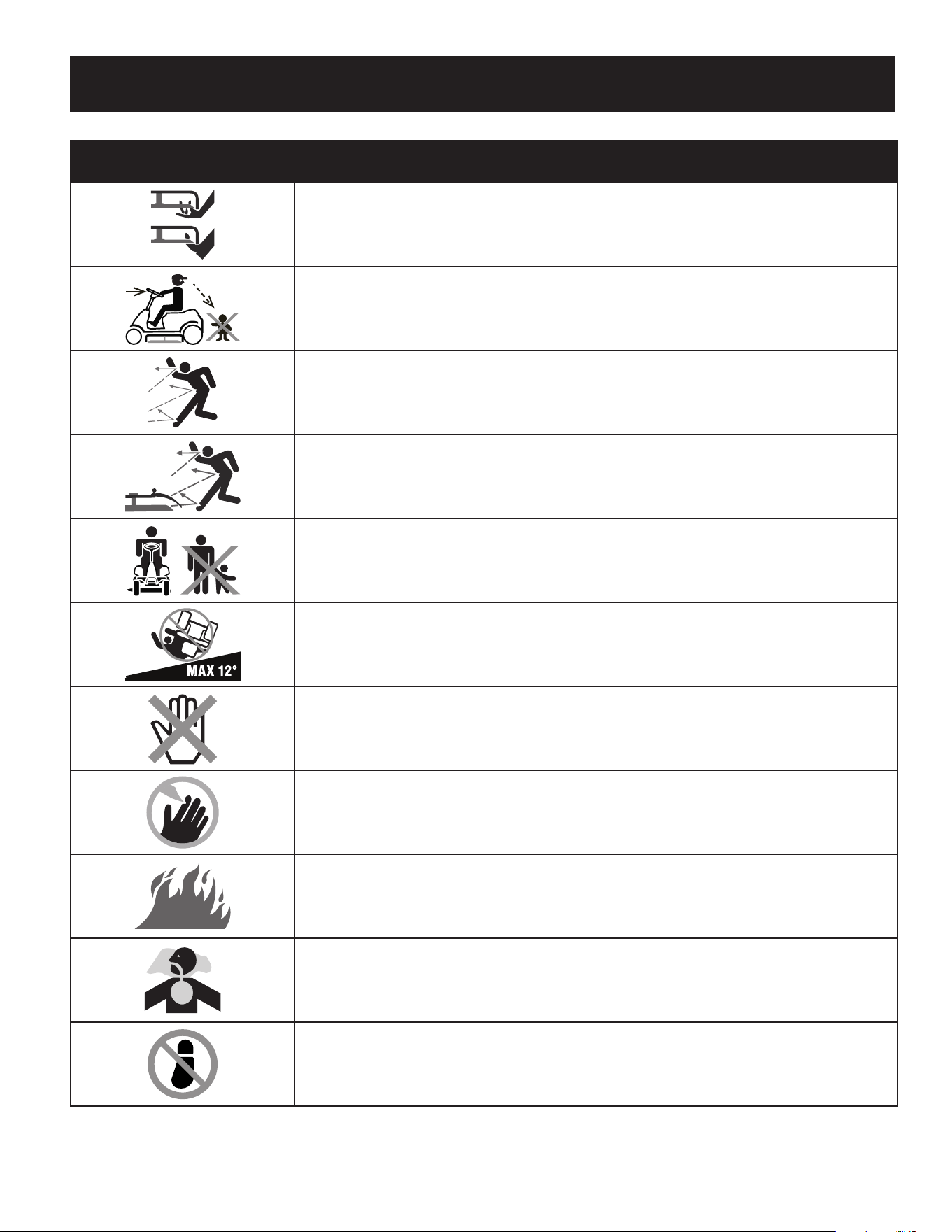
41
INSTRUCCIONES DE SEGURIDAD
Symbol Description
PELIGRO— DÉ EL CORTE DE PIE
Guarde manos y pies lejos de hacer girar partes.
PELIGRO— DÉ EL CORTE DE PIE
Retroceda lentamente. Siempre mire hacia abajo y hacia atrás antes y mientras retrocede, para evitar
accidentes.
PELIGRO— ESCOMBROS LANZADOS
Quite objetos que pueden ser lanzados por la lámina en cualquier dirección. Lleve gafas de seguri-
dad..
PELIGRO— ESCOMBROS LANZADOS
Quite objetos que pueden ser lanzados por la lámina en cualquier dirección. Lleve gafas de seguridad.
ERSONAS PRESENTES
Guarde a las personas presentes, a los ayudantes y a niños por lo menos 75 pies lejos.
PELIGRO— CUESTAS
Use extra la precaución en cuestas. No siegue cuestas mayores que 12.
ADVERTENCIA — SUPERFICIE CALIENTE
Las partes del motor, especialmente el silenciador, llega a ser muy caliente durante la operación.
Permita motor y silenciador para ponerse frío antes de tocar.
PELIGRO— GIRANDO HOJAS
Para reducir el riesgo de herida, guarde manos y pies lejos. No funcione a menos que la tapa de des-
carga o el receptor de hierba estén en su lugar apropiado. De ser dañado, sustituya inmediatamente.
GASOLINA DE ADVERTENCIA ES INFLAMABLE
Permita que el motor se enfríe al menos dos minutos antes del reabastecimiento de combustible.
ADVERTENCIA — MONÓXIDO DE CARBONO
Nunca dirijas un motor dentro o en un área mal ventilada. Los gases de combustión de motor con-
tienen el monóxido de carbono, un gas inodoro y mortal.
PELIGRO— DÉ EL CORTE DE PIE
No se pare sobre la plataforma de corte.
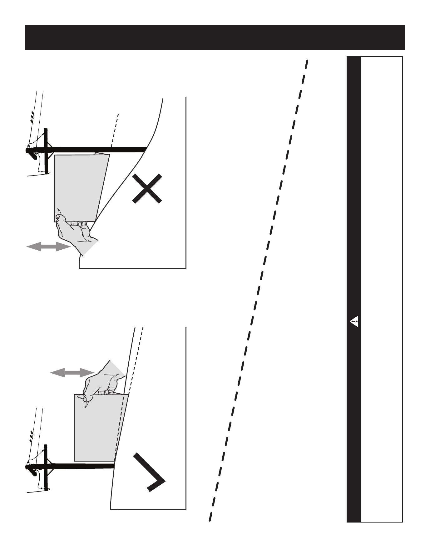
42
PENDIENTE DE CALIBRE
(ACEPTAR)
(DEMASIADO ESCARPADO)
USO DE ESTE PENDIENTE DE CALIBRE PARA DETERMINAR
SI UNA PENDIENTE ES DEMASIADO ESCARPADO PARA UNA OPERACIÓN SEGURA!
Para comprobar la pendiente, haga lo siguiente:
1. Borrar esta página y doble a lo largo de la línea discontinua.
2. Localizar un objeto vertical sobre o detrás de la pendiente (un poste, un edificio, una valla, un árbol, etc.)
3. Alinee cada lado de pendiente de calibre con el objeto vertical (consultar Figura 1 and Figura 2 ).
4. Ajuste el pendiente de calibre arriba o hacia abajo hasta los toques esquina izquierda el pendiente
(consultar Figura 1 and Figura 2).
5. Si hay un espacio por debajo de la pendiente de calibre, el pendiente es demasiado escarpa por operación
segura (consultar Figura 2 above).
12°
línea discontinua
Figura 2Figura 1
12° Pendiente
12° Pendiente
ADVERTENCIA
Las pendientes son un factor importante relacionado con un vuelco y renovación de los accidentes que pueden provocar lesiones
graves o la muerte. No utilice la máquina en pendientes de más de 12 grados. Todos pendientes requiere mayor precaución. Si no
puede retroceder en la pendiente o si se siente inseguro en ella, no la recorte. Siempre corte el césped arriba y abajo las pendientes,
nunca en toda la superficie de la cuesta.
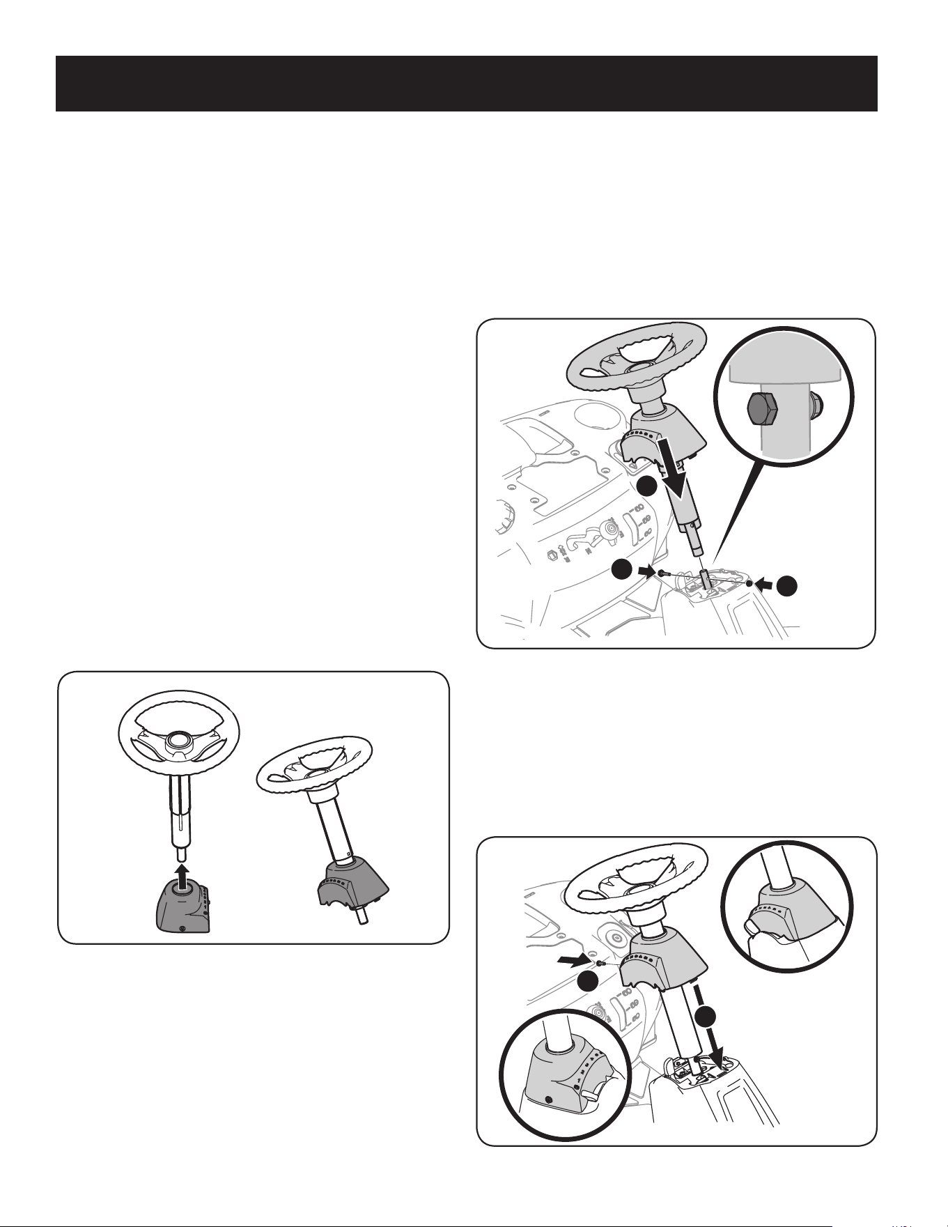
Contenido del paquete de elementos de ferretería
Antes de comenzar la instalación, extraiga todo el contenido de la caja y todos
los elementos de ferretería del paquete para comprobar que no falte nada.
Los elementos de ferretería se detallan a continuación. Los números de pieza
se indican entre paréntesis.
• Placa de enganche
• Soporte de montaje del asiento (con dos pernos con reborde y tuercas
de sujeción instalados)
Herramientas recomendadas para el montaje
• Llave de 3/8” (o de cubo) • Llave de cubo de 9” y 16”
• Llave de 1/2” (o de cubo) • Llave de 7/16”
• Llave de 5/8” (o de cubo) • Destornillador Phillips
• Llave de trinquete de 1/4”
Instalación del conjunto del volante
Si el conjunto del volante del tractor no vino ya instalado, siga los pasos a
continuación:
1. Deslice la tapa del pedestal sobre el árbol de la dirección de manera que
dicho eje se instale en el tractor, la tapa del pedestal quedará vertical como
se indica en la Figura 1.
Figura 1
2. Extraiga el perno con reborde y la tuerca de seguridad del árbol de la
dirección del tractor y guárdelos para los pasos posteriores.
3. Con el conjunto del volante vertical y ubicado de manera que quede sobre el
árbol inferior de la dirección del tractor, se debe alinear el volante de manera
que con las ruedas del tractor derechas, la abertura grande del volante esté
orientada hacia adelante.
Contenido del cajón
• Un tractor cortacésped • Un conjunto de asiento • Un conjunto de canal de descarga
• Un conjunto de rueda/eje de dirección • Una tapa trasera del motor • Un paquete de elementos de ferretería
• Una placa de enganche trasera • Una manga para drenado de aceite
• Un manual del operador del tractor cortacésped • Una tapa de pedestal de dirección
4. Baje el conjunto del volante sobre el árbol inferior de la dirección (1)
y sujételo con el perno y la tuerca de seguridad (2) que extrajo previamente.
Vea la Figura 2
1
2
2
Figura 2
5. Ajuste el perno con reborde y la tuerca de seguridad usando la llave de
9/16” y la llave de 7/16” o de cubo.
6. Extraiga el tornillo de montura de la tapa del pedestal instalado en
fábrica y ubicado en la consola de dirección del tractor. Guarde el tornillo
para uso posterior.
7. Deslice la tapa del pedestal sobre el tractor (1) y rótela ligeramente a la
derecha para calzarla en su lugar. Sujete el pedestal con el tornillo (2)
que extrajo antes. Vea la Figura 3.
1
2
Figura 3
43
MONTAJE
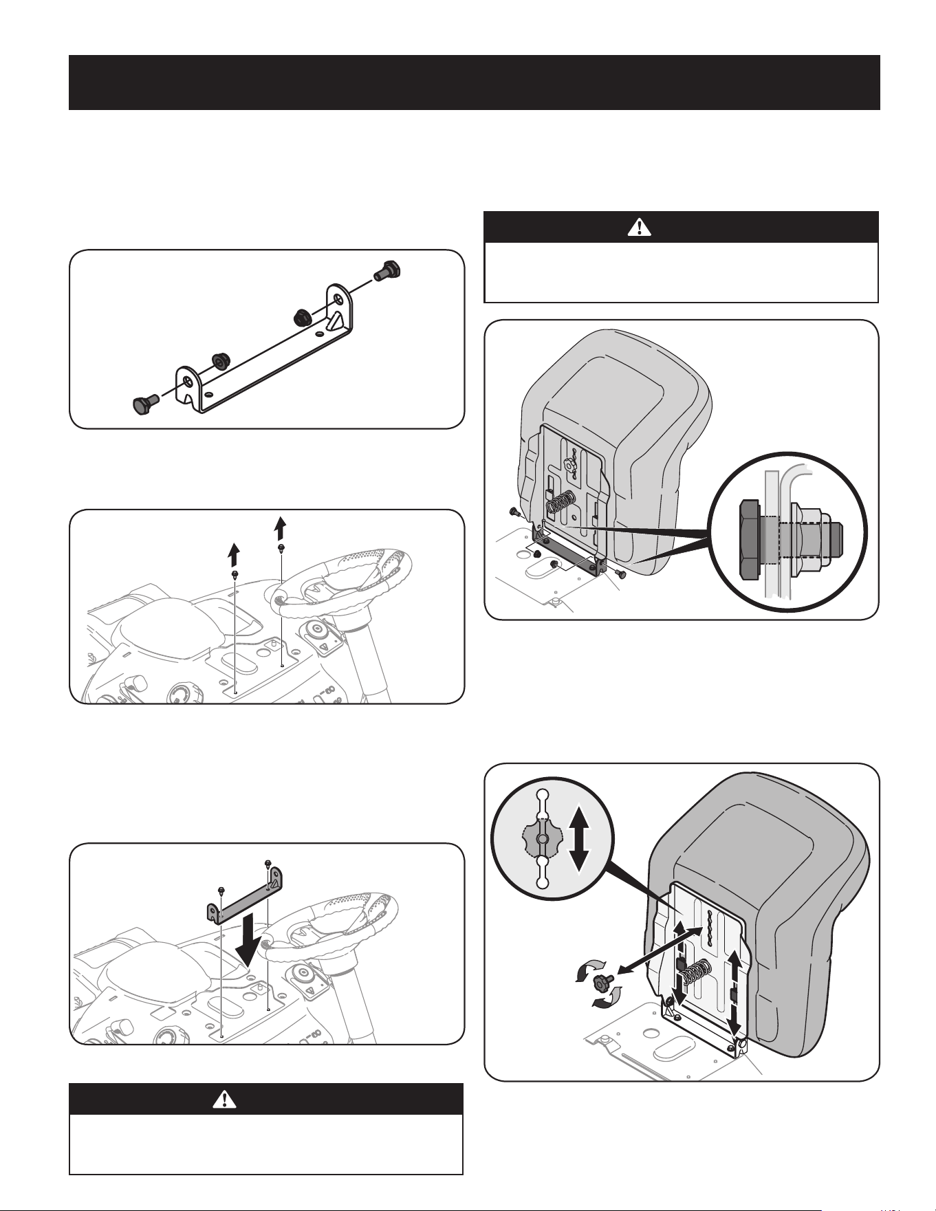
Instalación del asiento
Si su tractor no traía el asiento instalado de fábrica, siga las instrucciones
correspondientes que se incluyen a continuación para instalarlo.
1. Extraiga los dos pernos con reborde y las tuercas de seguridad del soporte
de montaje del asiento incluido en el paquete de elementos de ferretería.
Vea la Figura 4.
Figura 4
2. Extraiga los dos tornillos autorroscantes instalados en fábrica en el tractor.
Vea la Figura 5.
Figura 5
3. Alinee el soporte del asiento en su lugar sobre los orificios de los tornillos
autorroscantes que extrajo, como se indica en la Figura 6.
4. Con una llave de trinquete de 1/4 de pulgada y una llave de cubo de 3/8”,
sujete el soporte del asiento con los tornillos autorroscantes que extrajo
en el Paso 2. Vea la figura 6.
Figura 6
PRECAUCIÓN
No use ninguna herramienta eléctrica (por ejemplo, pistola de impacto
o taladro eléctrico con el extractor de tuercas colocado) para apretar los
pernos autorroscantes para sujetar el soporte del asiento.
5. Ubique el conjunto del asiento sobre el soporte de montaje del asiento,
alineando los orificios suministrados.
6. Instale los dos pernos con reborde y las tuercas de seguridad que extrajo del
soporte de montaje del asiento en el Paso 1. Vea la Figura 7.
PRECAUCIÓN
No use ninguna herramienta eléctrica (por ejemplo, pistola de impacto
o taladro eléctrico con el extractor de tuercas colocado) para apretar los
pernos autorroscantes para sujetar el soporte del asiento.
Figura 7
Ajuste del asiento
1. Para ajustar la posición del asiento, retire las dos perillas de ajuste que
están ubicadas en la parte inferior del asiento. Deslice el asiento hacia
adelante o hacia atrás, según lo desee. Vuelva a colocar la perilla de ajuste.
Consulte la Figura 8.
Figura 8
44
MONTAJE
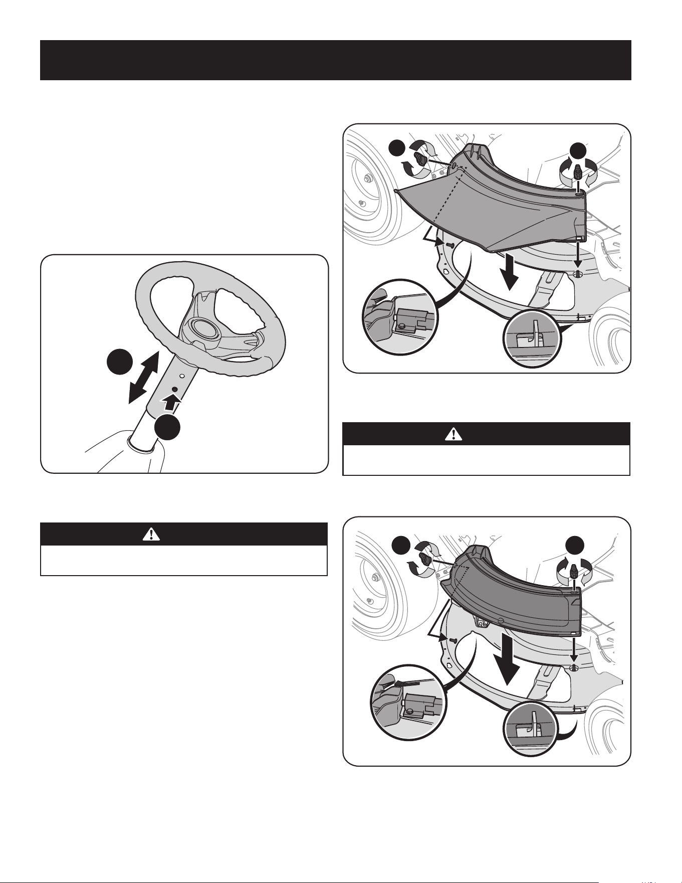
Ajuste de la altura del volante
Para ajustar la altura del volante, esta unidad está equipada con una columna de
volante telescópica. Para ajustar la altura del volante:
1. Siéntese en el asiento del operador y coloque las manos en el volante.
2. Pulse el botón de la columna de la dirección y eleve o baje el volante (b) hasta
la posición deseada. Vea la Figura 9.
Nota: Después de lograr la posición deseada, levante y baje el volante para
comprobar que se trabe en su lugar y que el botón (a) de la columna de la dirección
se suelte para quedar trabado. No opere esta unidad a menos que la columna de la
dirección esté en la posición en que queda trabada.
a
b
Figura 9
Instalación del canal de la plataforma
ADVERTENCIA
NUNCA opere este tractor si no tiene colocados el tapón de abono o el canal
de la plataforma.
1. Extraiga las perillas de aletas que instaló en la plataforma de corte y
guárdelas para colocarlas posteriormente.
2. Coloque el canal de la plataforma en la abertura de descarga sobre la
plataforma. Los prisioneros en la superficie de la plataforma calzarán en los
orificios de la parte superior del canal de la plataforma. La pequeña lengüeta
del borde de la plataforma calzará en el recorte cuadrado de la parte inferior
del canal de la plataforma. Vea el recuadro de la Figura 10.
Nota: Compruebe que la porción superior trasera del canal de la plataforma
está oprimiendo el interruptor de seguridad ubicado en la superficie de
la plataforma. El motor no arrancará si el canal de la plataforma no está
correctamente ubicado.
3. Sujete el canal de la plataforma ajustando las perillas de aleta que extrajo
antes. Vea la Figura 10.
1
2
Figura 10
Instalación del tapón mulch
ADVERTENCIA
NUNCA opere este tractor si no tiene colocados el tapón de abono o el canal
de la plataforma.
1. Retire las perillas de ala instaladas en la plataforma de corte y consérvelas
para una instalación posterior. Ver la Figura 11.
1
2
Figura 11
45
MONTAJE
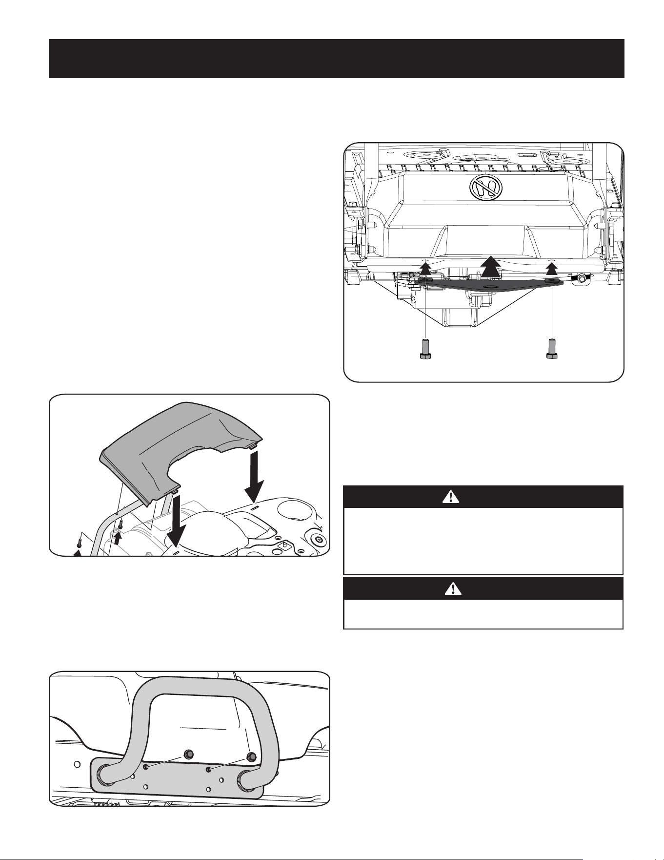
2. Instale el tapón de mulch en la abertura de descarga de la plataforma en la
plataforma. La parte posterior del tapón de mulch debe estar debajo de la
pestaña en el soporte de la plataforma trasera. Los postes en la superficie
de la plataforma encajarán a través de los orificios en la parte superior del
tapón de mulch. La pequeña pestaña en el área del labio de la plataforma se
ajustará a través del corte cuadrado en la parte inferior del tapón de mulch.
Vea la Figura 11.
Nota: Asegúrese de que la parte superior trasera del tapón de cobertura
esté presionando el interruptor de seguridad ubicado en la superficie de la
plataforma y debajo de la pestaña en el soporte de la plataforma trasera. El
motor no arrancará sin el tapón de mulch correctamente en su lugar.
3. Asegure el tapón de mulch apretando las perillas de aletas retiradas en el
paso 1.
Coloque la tapa trasera del motor
1. Extraiga los dos tornillos hexagonales instalados en fábrica ubicados en la
ménsula de montaje de la tapa trasera del motor. Guarde los tornillos para
uso posterior. Vea la Figura 12.
2. Coloque la tapa trasera del motor ubicándola en su lugar como se indica
en la Figura 12. Incline la tapa del motor hacia adelante para que calce
dentro de las ranuras provistas, luego rótela hacia atrás para alinear los
orificios de montaje.
Figura 12
3. Sujete la tapa con los dos tronillos hexagonales que extrajo antes.
No ajuste demasiado.
Instalación del paragolpes
1. Extraiga los dos tornillos como se indica en la Figura 13.
2. Ubique el paragolpes sobre los orificios de montaje y sujete con los elementos
de ferretería que extrajo en el Paso 1, como se indica en la Figura 13.
Figura 13
Instalación de la placa de enganche
1. Deslice la placa de enganche entre el marco y la cubierta trasera de su jinete.
Vea la Figura 14.
Figura 14
2. Cuando los orificios de la placa de enganche y el bastidor estén alineados,
instale los dos tornillos hexagonales de la bolsa manual a través del bastidor
y en la placa de enganche. Vea la Figura 14.
3. Apriete firmemente la placa de enganche.
Conexión de los cables de la batería
ADVERTENCIA
PROPOSICIÓN 65 DE CALIFORNIA
Los bornes de la batería y los accesorios afines contienen plomo y
compuestos de plomo, sustancias químicas que según lo establecido por
el Estado de California causan cáncer y daños en el sistema reproductivo.
Lávese las manos después de estar en contacto con estos componentes.
PRECAUCIÓN
Cuando coloque los cables de la batería, conecte siempre primero el cable
POSITIVO (rojo) a su borne, y a continuación el cable NEGATIVO (negro).
Por razones relacionadas con el embarque, los dos cables de la batería de su equipo
pueden haber sido desconectados de los bornes en fábrica. Para conectar los cables
de la batería, proceda de la siguiente manera:
NOTA: El borne positivo de la batería está marcado como Pos (+). El borne negativo
de la batería está marcado como Neg (−).
1. Extraiga los pernos y las tuercas hexagonales instalados en fábrica ubicados
en el extremo del mazo de cables. Guarde las piezas para uso posterior.
2. Retire la cubierta plástica, si es que está presente, del borne positivo de la
batería y una el cable rojo al borne positivo de la batería (+) con un perno y
su tuerca hexagonal usando una llave de 7/16 pulgadas y una llave de cubo.
Vea la Figura 11.
3. Retire la cubierta plástica, si es que está presente, del borne negativo de la
batería y una el cable negro al borne negativo de la batería (–) con el otro
perno y tuerca hexagonal usando la llave de 7/16 pulgadas y la llave de cubo.
Vea la Figura 15.
46
MONTAJE
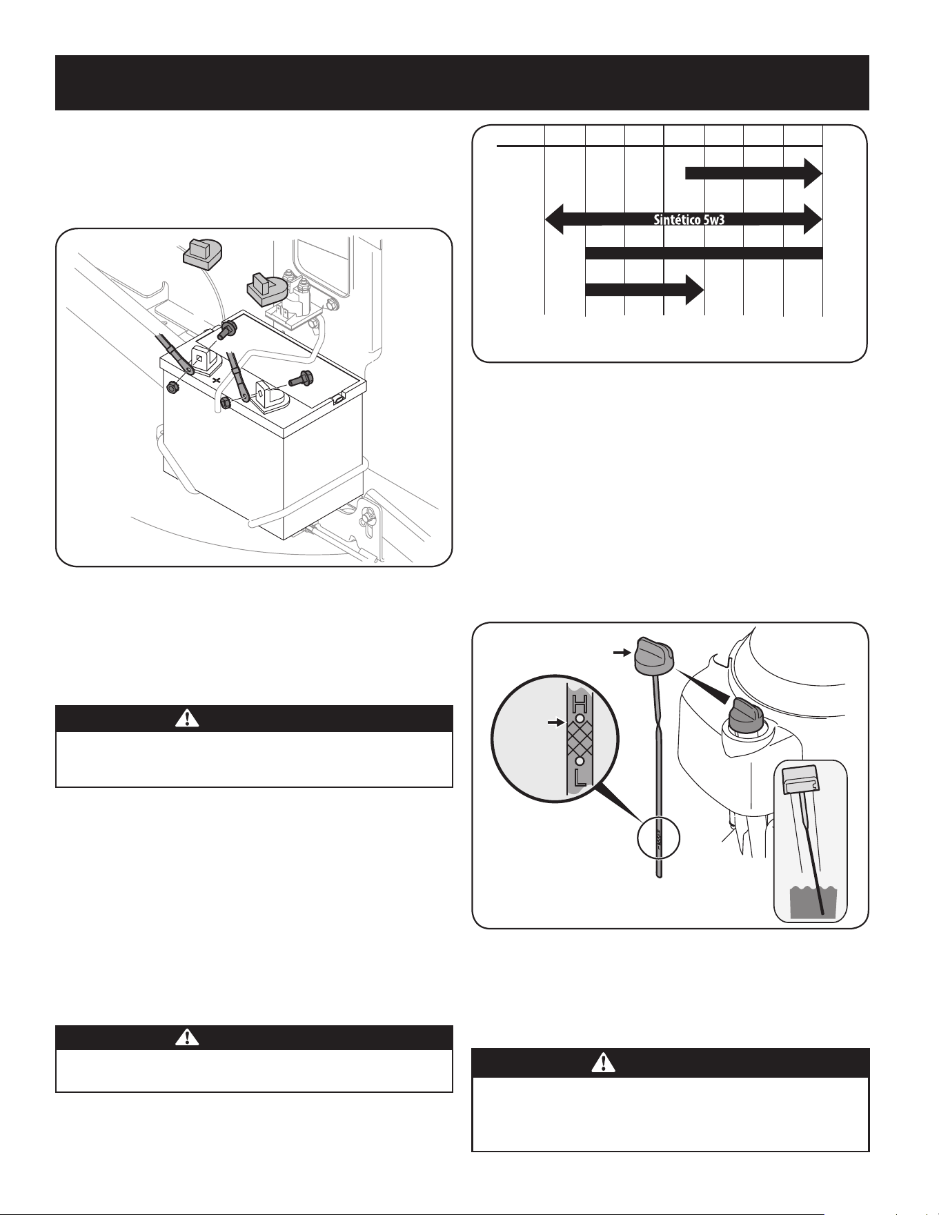
4. Coloque el capuchón de goma rojo por encima del borne positivo de la batería
para protegerlo contra la corrosión.
NOTA: Si la batería se pone en servicio después de la fecha indicada en su parte
superior o al costado de la misma, cárguela siguiendo las instrucciones de la sección
Mantenimiento de este manual del operador antes de hacer funcionar el tractor.
Figura 15
Gasolina y aceite
NOTA: El motor se envía sin gasolina y con aceite para motor en su interior. Sin
embargo, usted DEBE controlar el nivel de aceite antes de hacerlo funcionar. Tenga
cuidado de no llenar en exceso. Si se hace funcionar el motor sin suficiente aceite
puede dañarse gravemente y se anula la garantía.
ADVERTENCIA
Siempre mantenga las manos y los pies alejados de las piezas móviles del
equipo. No utilice fluidos comprimidos para arrancar. Los vapores son
inflamables.
Recomendaciones sobre el aceite
Antes de arrancar el motor, compruebe el nivel de aceite, la capacidad es 1700
ml/57.5 fl. onza Consulte la tabla de viscosidad en la Figura 16 para obtener
recomendaciones acerca del aceite. No sobre-relleno. Utilice un 4 tiempos, o un
alto poder detergente equivalente, aceite de motor de primera calidad certificada
para cumplir o exceder los requisitos del fabricante de automóviles EE.UU. para la
clasificación de servicio de un SJ nivel mínimo (calificaciones de letras superiores
son aceptables como SL y grados SM). El aceite de motor mostrará esta designación
en el envase.
Se recomienda SAE 10W-30 para uso general, a todas las temperaturas. Si utiliza
aceite con viscosidad monogrado, seleccione en la tabla de la página siguiente la
viscosidad adecuada para la temperatura media de su zona.
PRECAUCIÓN
No utilice aceites sin detergente ni aceite para motor de dos tiempos.
Podría reducirse la vida útil del motor.
NOTA: Se puede usar un aceite sintético 5w30 para mejorar el encendido cuando el
clima está frío (temperaturas inferiores a los 40°F).
-30º -20º -10º 0º
0º 15º 30º 50º 70º 85º 105º
10º 20º 30º 40º
-20º
(ºC)
(ºF)
5W-30
30
10W-30
Figura 16
Control del nivel de aceite
NOTA: Asegúrese de comprobar el aceite sobre una superficie nivelada y con el
motor apagado.
1. Retire el tapón de llenado/varilla de medición de aceite y limpie bien la varilla.
2. Inserte la varilla de medición de nivel dentro del cuello de llenado de aceite.
Gire la varilla de medición 1/4 de giro hasta la posición en la que queda
trabada para que se asiente por completo. Vea la Figura 17.
3. Retire la varilla de medición de nivel para controlar el nivel de aceite.
4. Si el nivel está bajo, agregue aceite lentamente hasta que la medición está
en el límite superior de la varilla de medición. Vea el recuadro de la Figura 15.
5. Vuelva a colocar la varilla de medición y gírela hasta la posición en que
queda trabada antes de arrancar el motor.
Figura 17
NOTA: No lo llene en exceso. El exceso de aceite puede causar ahumado,
problemas de arranque, suciedad en la bujía y saturación de aceite en el
purificador de aire.
Requisitos de combustible
PRECAUCIÓN
Si se opera el motor con combustible E85, una mezcla de aceite/gasolina,
gasolina sucia o
gasolina con más de 30 días de uso
que no se haya
estabilizado con un aditivo de combustible, se puede dañar el carburador del
motor. A los daños subsiguientes no los cubre la garantía de Craftsman.
Upper
Level
Tapón de llenado de aceite/
varilla de medición del
nivel de aceite
Nivel
superior
47
MONTAJE

Utilice gasolina para automóviles (sin plomo o bajo contenido de plomo para
minimizar los depósitos en la cámara de combustión) con un mínimo de 87 octanos.
Se puede usar gasolina con hasta un 10% de etanol o un 15% de MTBE (éter metílico
terciario-butílico). Nunca use una mezcla de aceite y gasolina ni gasolina sucia. Evite
que se introduzca suciedad, polvo o agua en el depósito de combustible. NO utilice
gasolina E85.
ADVERTENCIA
Tenga mucho cuidado al trabajar con gasolina. La gasolina es sumamente
inflamable y sus vapores pueden causar explosiones. Nunca cargue combustible
en la máquina en un espacio cerrado o cuando el motor está caliente o en
marcha. Apague cigarrillos, cigarros, pipas y otras fuentes de combustión.
NOTA: Compre gasolina en pequeñas cantidades. No use gasolina que haya quedado
de la temporada anterior, para minimizar la formación de depósitos de goma en el
sistema de combustible.
• Este motor está habilitado para funcionar con gasolina sin plomo. Para
obtener el mejor resultado, llene el depósito de combustible únicamente con
gasolina sin plomo limpia y fresca, en un surtidor que indique un octanaje
igual a 87 o más.
• El gasohol (hasta 10% de alcohol etílico, 90% de gasolina sin plomo por
volumen) es un combustible aprobado. No se aprueba el uso de otras
mezclas de gasolina/alcohol, como la E85.
• El éter metílico terciario-butílico (MTBE) y las mezclas de gasolina sin
plomo (hasta un máximo de 15% de MTBE por volumen) son combustibles
aprobados. No se aprueba el uso de otras mezclas de gasolina/éter.
• Llene el depósito de combustible al aire libre o en un área bien ventilada.
• No llene en exceso el depósito de combustible. Llene el depósito no más de
1/2 pulgada por debajo de la base del cuello de llenado para dejar espacio
para la expansión del combustible.
• Nunca saque la tapa del combustible ni agregue combustible mientras el
motor está caliente o en marcha. Deje que el motor se enfríe por lo menos
dos minutos antes de volver a cargar combustible.
• Limpie el combustible que se haya derramado sobre el motor y el equipo.
Traslade la máquina a otra zona. Espere 5 minutos antes de encender el motor.
Procedimiento para agregar gasolina
NOTA: El tractor se sujeta con una tapa de combustible que está amarrada y tiene
una llave de trinquete. PARE de cargar después de que se vea combustible dentro
del cuello de llenado. Esto asegura que hay un volumen de expansión adecuado, de
lo contrario el combustible puede rebalsar generando una situación de peligro.
NO llene al máximo el depósito de combustible.
• Cargue combustible en un área bien ventilada y con el motor apagado.
No fume ni permita llamas o chispas en el lugar donde se carga
combustible o se almacena la gasolina.
• No llene en exceso el depósito de combustible. Después de cargar
combustible, asegúrese de que el tapón del depósito esté bien cerrado y
asegurado.
• Tenga cuidado de no derramar combustible al realizar la recarga.
El combustible derramado o sus vapores se pueden incendiar. Si se derrama
combustible, asegúrese de que el área esté seca antes de arrancar el motor.
• Evite el contacto repetido o prolongado con la piel y la inhalación
de los vapores.
Carga de combustible
ADVERTENCIA
El combustible debe cargarlo un adulto. NUNCA permita que un niño
recargue combustible en el motor. Los vapores de la gasolina (el
combustible) son sumamente inflamables y pueden explotar. Los vapores
del combustible se pueden esparcir y encenderse por una chispa o llama
que esté a mucha distancia del motor. Para evitar lesiones o muertes por
incendios de combustible, siga estas instrucciones:
• NO use combustible con plomo.
• El combustible debe ser nuevo y estar limpio. NUNCA use el combustible que
queda desde la última temporada o que quedó almacenado durante períodos
prolongados.
• NUNCA mezcle aceite con combustible.
• NO use combustible que contenga metanol (alcohol de madera).
NOTA: Antes de recargar combustible, deje que el motor se enfríe dos minutos.
1. Apague el motor y déjelo enfriar al menos dos minutos antes de quitar la
tapa de llenado de combustible. El depósito de gasolina está ubicado debajo
del asiento. El tapón del combustible está amarrado al tractor para impedir
que se pierda. No intente retirar el tapón del tractor.
2. Antes de sacar el tapón para cargar combustible, limpie alrededor.
3. Cargue el depósito hasta que el combustible llegue a 1⁄2 pulgada por debajo
de la base del cuello de llenado para dejar espacio para la expansión del
combustible. Tenga cuidado de no llenar en exceso. Vea la Figura 18.
Figura 18
4. Vuelva a colocar la tapa de la gasolina y ajústela bien. Antes de poner en
marcha el motor, debe limpiar el combustible que se haya derramado. Si se
derrama combustible NO ponga en marcha el motor. Mueva la máquina para
alejarla de la zona del derrame. Evite generar una fuente de encendido hasta
que los vapores del combustible hayan desaparecido.
Presión de los neumáticos
ADVERTENCIA
Se debe mantener una presión uniforme para todos los neumáticos en todo
momento. Nunca exceda la presión máxima de inflado que se indica en los
laterales de los neumáticos.
La presión operativa recomendada para los neumáticos es:
• Aproximadamente 10 psi para los neumáticos traseros
• Aproximadamente 14 psi para los neumáticos delanteros
IMPORTANTE:
Consulte los laterales de las ruedas para conocer con exactitud la
presión máxima en psi recomendada por el fabricante. No los infle en exceso.
Una presión de neumáticos despareja podría hacer que la plataforma no corte
el césped parejo.
48
MONTAJE
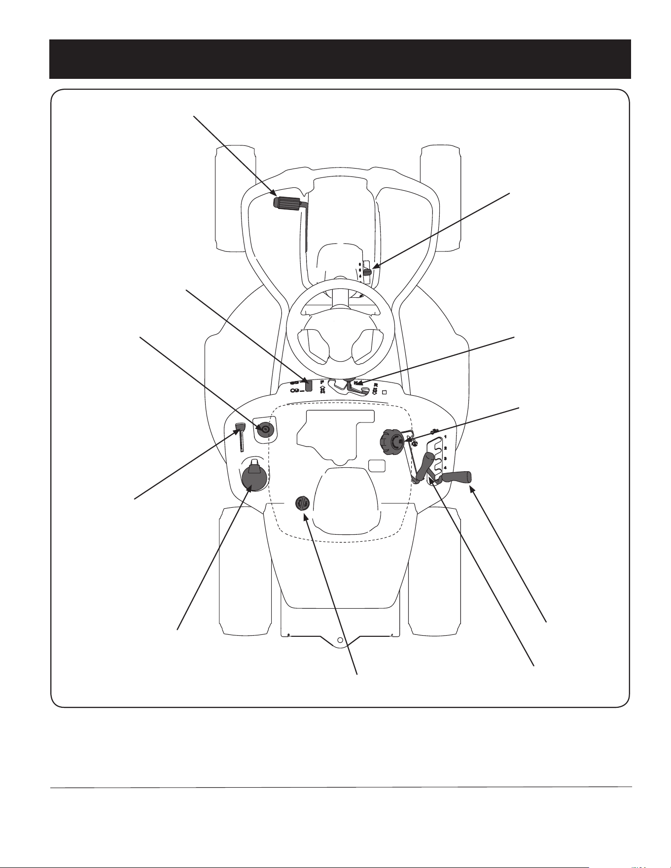
49
FUNCIONAMIENTO
Pedal de freno/embrague
Palanca de control de
velocidad y freno de mano
Palanca de cambios
Portacubeta
Palanca de acelerador/
estrangulador
Interruptor de encendido
Palanca de elevación
de la plataforma
Palanca de la toma de fuerza (PTO)
(enganche de cuchilla)
Tapón de llenado de aceite
Tapón de llenado
de combustible
Indicador de nivel de
combustible
Figura 17
NOTA: Cualquier referencia hecha en este manual al lado DERECHO o IZQUIERDO del tractor debe entenderse tal como se observa desde la posición del operador
cuando está sentado hacia adelante orientado al frente del tractor.
Cumple con las normas de seguridad de ANSI
Los tractores Craftsman cumplen con las normas de seguridad del Instituto Nacional Americano de Normalización (ANSI).
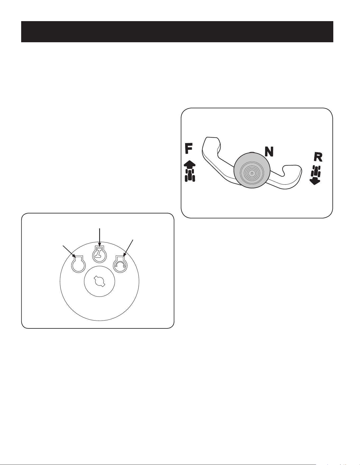
50
FUNCIONAMIENTO
Palanca de cambios
La palanca de cambios está ubicada en el panel de control justo debajo del asiento,
en el centro del tractor. Tiene tres posiciones, ADELANTE, PUNTO MUERTO y ATRÁS.
Cuando mueva la palanca de cambios, el pedal del freno debe estar presionado
a fondo y el tractor no debe estar en movimiento. Vea la Fig. 19.
IMPORTANTE: Nunca fuerce la palanca de cambios. De hacerlo, puede dañarse
seriamente la transmisión del tractor.
Figura 19
Palanca de control de velocidad
La palanca de control de velocidad, ubicada del lado derecho de la consola de
dirección del tractor, le permite regular la velocidad de piso del tractor corta césped.
Para utilizarla, presione el pedal del embrague-freno, saque la palanca de la muesca
del freno de estacionamiento y llévela hacia adelante para aumentar la velocidad de
piso del tractor. Cuando haya alcanzado la velocidad deseada, suelte la palanca en la
muesca adecuada para mantener esa velocidad.
Para reducir la velocidad de piso del tractor, presione el pedal del embrague-freno,
lleve la palanca de control de velocidad hacia atrás y suéltela dentro de una muesca.
Freno de mano
Para colocar el freno de mano, presione a fondo el pedal del embrague-freno
Mueva la palanca de control de velocidad totalmente hacia abajo en la posición de
freno de mano. Suelte el pedal del embrague-freno para permitir que el freno de
mano engrane.
Para soltar el freno de mano, presione el pedal del embrague-freno, saque la palanca
de control de velocidad de la posición de freno de mano y llévela a la posición
deseada. Suelte el pedal de embrague-freno.
NOTA: Si el operador abandona el asiento y deja el motor en funcionamiento,
deberá colocar el freno de mano, o el motor se apagará de forma automática.
Indicador de nivel de combustible
El indicador de nivel de combustible está ubicado debajo del asiento a la izquierda
de la posición del operador en el panel de control. Use esta ventana para identificar
los requerimientos de combustible del tractor. Vea la Fig. 20.
Control del acelerador/estrangulador
La palanca de control del acelerador está ubicada en el guardabarros izquierdo del
tractor si se sienta en la posición del operador, vea la Fig. 17. Esta palanca controla la
velocidad del motor, así como el cebador cuando se lo empuja completamente hacia
adelante. Cuando se lo coloca en una posición determinada, el acelerador mantiene
una velocidad de motor uniforme.
IMPORTANTE: Cuando opere el tractor con la plataforma de corte colocada,
asegúrese de que la palanca del acelerador esté siempre en la posición FAST
(rápida; representada por una liebre).
Si se mueve la palanca del acelerador totalmente hacia adelante, se activa el control
del estrangulador del motor. Al activar el control del estrangulador se cierra la placa
del estrangulador del carburador y esto ayuda a poner en marcha el motor.
Consulte Arranque del motor en la sección Funcionamiento de este manual para ver
instrucciones de arranque detalladas.
Interruptor de encendido
El interruptor de encendido está ubicado en el guardabarros izquierdo del tractor si
se sienta en la posición del operador, adyacente al control del acelerador/cebador.
Para encender el motor, active la llave en el interruptor de encendido insertando la
llave en el interruptor de encendido y gírela en el sentido de las agujas del reloj hasta
la posición START (encendido). Suelte la llave en la posición ON (encendido) una vez
que haya arrancado el motor. Vea la Fig. 18.
Apagado
Encendido
Arranque
Figura 18
Pedal de freno-embrague
El pedal del embrague-freno está ubicado del lado izquierdo del tractor corta césped,
a lo largo del estribo. Presione el pedal del embrague-freno parcialmente hacia
abajo cuando disminuya la velocidad del tractor cambiando de marchas (Consulte la
sección Palanca de control de velocidad). Presione el pedal totalmente hacia abajo
para colocar el freno de disco y hacer que el tractor se detenga por completo.
NOTA: Se debe oprimir completamente el pedal del embrague-freno para poner
en marcha el motor. Consulte Interruptores de Bloqueo de Seguridad en la sección
Funcionamiento de este manual.
DETEN ER
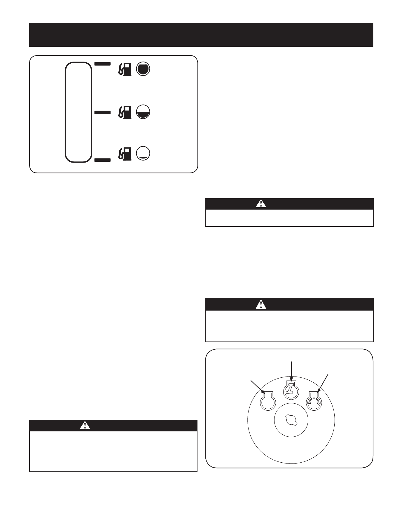
51
FUNCIONAMIENTO
Figura 20
Palanca de elevación de la plataforma
Ubicada en el guardabarros derecho del tractor, la palanca de elevación de la
plataforma se utiliza para cambiar la altura de la plataforma de corte. Para utilizarla,
mueva la palanca hacia la izquierda, luego colóquela en la muesca que mejor se
adapte a la aplicación deseada.
Palanca de la toma de fuerza (PTO)
(enganche de cuchilla)
Ubicada en el guardabarros derecho del tractor, la palanca de toma de fuerza (PTO)
(enganche de cuchilla) se usa para dar energía a la plataforma de corte. Para hacerla
funcionar, mueva la palanca totalmente hacia adelante. Moviendo la palanca
totalmente hacia atrás, en la posición PTO OFF (toma de fuerza desconectada), se
corta la energía a la plataforma de corte.
NOTA: Al encender el motor, la palanca PTO (enganche de cuchilla) debe encontrarse
en posición desconectada (PTO OFF).
Tapón de llenado de combustible
El tapón de llenado de combustible está ubicado debajo del asiento. Consulte
la sección Montaje de este manual para obtener instrucciones sobre la carga de
combustible del tractor.
Tapón de llenado de aceite
El tapón de llenado de aceite está ubicado debajo del asiento. Consulte la sección
Montaje de este manual para obtener instrucciones para controlar y agregar
combustible al tractor.
Tapón de llenado de combustible
El depósito de gasolina está ubicado debajo del asiento. No lo llene en exceso.
ADVERTENCIA
Tenga mucho cuidado al trabajar con gasolina. La gasolina es sumamente
inflamable y sus vapores pueden causar explosiones. Nunca cargue
combustible en la máquina en un espacio cerrado o cuando el motor está
caliente o en marcha. Apague cigarrillos, cigarros, pipas y otras fuentes
de combustión.
Para obtener información detallada sobre cómo agregar combustible, consulte
Requisitos de combustible en la sección Montaje de este manual.
Interruptores de bloqueo de seguridad
El sistema de bloqueo de seguridad está diseñado para que el tractor funcione con
seguridad. Si dicho sistema funciona mal, no se debe hacer funcionar el tractor.
Comuníquese de inmediato al 1-888-331-4569 para solicitar el servicio de
mantenimiento y reparación del sistema.
• El sistema de bloqueo de seguridad impide que el motor arranque a menos
que esté colocado el freno de mano, y la palanca de toma de fuerza (PTO)
(enganche de cuchilla) esté en posición desconectada (OFF).
• Si el operador abandona su asiento antes de colocar el freno de mano, el
sistema de bloqueo de seguridad apaga automáticamente el motor.
• Si el operador abandona su asiento con la palanca de la PTO (enganche
de cuchilla) conectada, el sistema de bloqueo de seguridad apaga
automáticamente el motor, independientemente de que el freno de
mano esté puesto o no.
• El motor se apagará automáticamente si la palanca de la PTO (enganche de
cuchilla) se coloca en posición enganchada (ON) con la palanca de cambios
en posición marcha atrás.
ADVERTENCIA
No opere el tractor si el sistema de bloqueo funciona mal. El sistema fue
diseñado para brindarle seguridad y protección.
Interruptor de encendido
El interruptor de encendido se activa para arrancar el motor. Inserte la llave en el
interruptor de encendido y gire en el sentido de las agujas del reloj a la posición
START (arranque). Suelte la llave en la posición ON (encendido) una vez que haya
arrancado el motor. Vea la Fig. 21.
Para detener el motor, gire la llave de encendido en sentido contrario a las agujas del
reloj hasta la posición OFF (apagado). Vea la Fig. 21.
ADVERTENCIA
Nunca deje la máquina en funcionamiento sin vigilancia. Corte siempre la
PTO, mueva la palanca de cambios a la posición Neutral (punto muerto),
ponga el freno de mano, pare el motor y retire la llave, para evitar que
alguien encienda accidentalmente el motor.
Apagado
Encendido
Arranque
Figura 21
DETEN ER

52
FUNCIONAMIENTO
WARNING
Evite lesiones graves o la muerte
• Conozca la ubicación y función de todos los controles.
• Extraiga los objetos que podrían ser arrojados por las cuchillas.
• Recorra las pendientes hacia arriba y hacia abajo, no de manera transversal.
• Tenga sumo cuidado en las pendientes. No corte el césped en pendientes
de más de 12°. Evite realizar giros abruptos. Conduzca a baja velocidad.
• No utilice la unidad en lugares donde podría resbalar o volcar.
• Si la máquina se para mientras sube la pendiente, pare las cuchillas y
retroceda lentamente para abajo.
• Antes de abandonar la posición del operador, desconecte las cuchillas,
ponga el freno de mano, apague el motor y saque la llave.
• Asegúrese que las cuchillas y el motor se detengan antes de colocar las
manos o los pies cerca de las cuchillas.
• Mantenga los dispositivos de seguridad (guardas, protectores,
interruptores, etc.) en su lugar y en funcionamiento.
• Mantenga alejados a los observadores.
• Deje que se enfríe el motor antes de almacenar o transportar la unidad.
• Mantenga la máquina libre de residuos.
Lea el Manual del operador
Colocación del freno de mano
Para colocar el freno de mano:
1. Presione totalmente el pedal del freno y manténgalo hacia abajo con el pie.
2. Mueva la palanca del freno de mano hacia abajo hasta la posición
de freno de mano.
3. Suelte el pedal del freno para permitir que el freno de mano quede puesto.
Para sacar el freno de mano:
1. Oprima el pedal del freno y mueva la palanca de control de velocidad hasta
que quede fuera de la posición de freno de mano.
Fijación de la altura de corte
Seleccione la posición de altura de la plataforma de corte colocando la palanca de
elevación de la plataforma en cualquiera de las muescas de diferente altura de corte,
del lado derecho del guardabarros.
ADVERTENCIA
Mantenga las manos y pies alejados de la abertura de descarga de la
plataforma de corte.
Encendido del motor
ADVERTENCIA
No opere el tractor si el sistema de bloqueo funciona mal. El sistema fue
diseñado para brindarle seguridad y protección.
NOTA: Consulte la sección Montaje de este manual para obtener instrucciones sobre
el llenado de aceite y gasolina.
1. Inserte la llave del tractor en el interruptor de encendido.
2. Coloque la palanca de la PTO (enganche de cuchilla) en la posición OFF
(desconectada).
3. Coloque el freno de mano del tractor.
4. Active el control del estrangulador.
5. Gire la llave de encendido en el sentido de las agujas del reloj hasta la
posición START (arranque). Una vez que arranque el motor, suelte la llave.
Volverá a la posición ON.
ADVERTENCIA
IMPORTANTE: NO mantenga la llave en la posición START (arranque)
durante más de diez segundos por vez. Si lo hace, puede ocasionar daños al
arrancador eléctrico del motor.
6. Después de que arranque el motor, desactive el control del cebador
colocando el control del acelerador en la posición FAST (rápida).
NOTA: NO deje el control del cebador activado mientras opera el tractor. Si lo hace,
se generará una mezcla de combustible “rica”, lo cual hará que el motor no
funcione bien.
Detención del motor
ADVERTENCIA
Si golpea contra algún objeto extraño, detenga el motor, desconecte el(los)
cable(s) de la bujía y conecte el motor a masa. Inspeccione minuciosamente
la máquina para ver si está dañada. Repare el daño antes de volver a
encender el motor y operar la máquina.
1. Si las cuchillas están enganchadas, coloque la palanca de la PTO
(enganche de cuchilla) en la posición OFF (desconectada).
2. Gire la llave de encendido en sentido contrario a las agujas del reloj
a la posición STOP (parar).
3. Retire la llave del interruptor de encendido para evitar que alguien
encienda accidentalmente el motor.

53
FUNCIONAMIENTO
Si la unidad se detiene con el control de velocidad en la posición de alta velocidad,
o si la unidad no funciona con la palanca de control de velocidad en la posición de
baja velocidad, realice lo siguiente:
1. Coloque la palanca de cambios en posición NEUTRAL (punto muerto).
2. Vuelva a encender el motor.
3. Coloque la palanca de control de velocidad en la posición de
velocidad más alta.
4. Suelte completamente el pedal del embrague-freno.
5. Presione el pedal del embrague-freno.
6. Coloque la palanca de control de velocidad en la posición deseada.
7. Coloque la palanca de cambios en la posición FORWARD (marcha adelante)
o REVERSE (marcha atrás), y siga el procedimiento normal de operación.
Operación en pendiente
Consulte el INDICADOR DE PENDIENTES en la sección Instrucciones de seguridad
del manual para contribuir a determinar en qué pendientes puede operar el tractor
con seguridad.
ADVERTENCIA
No corte en pendientes con una inclinación de más de 12° (elevación
aproximada de 2 pies por cada 10 pies). El tractor podría voltearse y causar
lesiones severas.
• En las pendientes corte hacia arriba y hacia abajo, NUNCA en
forma transversal.
• Tenga mucho cuidado al cambiar de dirección en una pendiente.
• Esté atento a los hoyos, surcos, baches, rocas u otros objetos ocultos.
El terreno desnivelado puede voltear la máquina. El césped alto puede
ocultar obstáculos.
• Evite realizar giros cuando opere en una pendiente. Si debe realizar un giro,
hágalo pendiente abajo. Subir una pendiente aumenta enormemente las
posibilidades de que el vehículo dé una vuelta de campana.
• Evite detenerse cuando suba una pendiente. Si fuese necesario detenerse
mientras sube una pendiente, arranque suave y cuidadosamente para reducir
la posibilidad de que el tractor se dé vuelta hacia atrás.
Conducción del tractor
ADVERTENCIA
Evite arrancar súbitamente, desarrollar excesiva velocidad y detenerse
de repente.
ADVERTENCIA
No abandone el asiento del tractor sin colocar primero la PTO (enganche de
cuchilla) en la posición OFF (desconectada), presionar el pedal del freno y
colocar el freno de mano. Si deja el tractor sin vigilancia, apague el motor y
retire la llave de encendido.
ADVERTENCIA
Siempre mire hacia abajo y hacia atrás antes y mientras se desplaza marcha
atrás, para evitar un accidente.
1. Oprima el pedal del freno y mueva la palanca de control de velocidad
hasta que quede fuera de la posición de freno de mano, luego deje que
se suelte el freno.
2. Mueva la palanca del acelerador a la posición FAST (RÁPIDA,
representada por una liebre).
3. Coloque la palanca de cambios en posición FORWARD
(marcha adelante) o REVERSE (marcha atrás).
IMPORTANTE: NO use la palanca de cambios para cambiar la dirección de
desplazamiento mientras el tractor esté en movimiento. Siempre use el
pedal de freno para detener el tractor por completo antes de hacer el cambio.
4. Suelte el freno de mano presionando el pedal del embrague-freno
y colocando la palanca de control de velocidad en la posición deseada.
IMPORTANTE: Quienes utilicen la máquina por primera vez deben usar
las posiciones de velocidad 1 ó 2. Familiarícese por completo con el
funcionamiento y los controles del tractor antes de operar la máquina
en posiciones de mayor velocidad.
5. Suelte el pedal del embrague-freno lentamente para poner la unidad
en movimiento.
6. El tractor corta césped se detiene presionando el pedal del embrague-freno.
NOTA: Al operar la unidad inicialmente, habrá poca diferencia entre las dos
velocidades más altas hasta que las correas se hayan asentado en las poleas
durante el período de ablande.
ADVERTENCIA
Antes de abandonar la posición del operador, desenganche las cuchillas, coloque
la palanca en neutral, coloque el freno de estacionamiento, apague el motor y
retire la llave de encendido.
IMPORTANTE: Siempre que detenga el tractor por cualquier razón en un área de
césped, haga lo siguiente:
1. Coloque la palanca de cambios en punto muerto,
2. Coloque el freno de mano,
3. Apague el motor y retire la llave. Eso permitirá reducir al mínimo la
posibilidad de que su césped resulte “quemado” por el escape caliente del
motor en funcionamiento.

54
FUNCIONAMIENTO
Corte de césped
WARNING
Para tratar de evitar el contacto con las cuchillas o una lesión por algún
objeto que sea arrojado, mantenga a los observadores, a los ayudantes,
niños y mascotas alejados al menos 25 metros de la máquina mientras está
en funcionamiento. Detenga la máquina si alguien se acerca.
La siguiente información será de utilidad cuando use la plataforma de corte
con su tractor:
WARNING
Planifique el patrón de corte, para evitar que la descarga de materiales se
realice hacia los caminos, las veredas, los observadores, etc. Evite además
descargar material contra una pared u obstrucción, ya que esto podría hacer
que el material descargado rebote contra el operador.
• No corte a alta velocidad de piso, especialmente si tiene instalado un kit de
abono o un colector de césped.
• Para obtener los mejores resultados, se recomienda realizar los dos primeros
cortes de césped arrojando la descarga hacia el centro. Después de las dos
primeras vueltas, cambie la dirección para arrojar la descarga hacia afuera,
para equilibrar el corte. Esto otorgará un mejor aspecto al césped.
• No corte el césped demasiado corto. El césped corto es propicio para
el crecimiento de malezas y se pone amarillo rápidamente cuando
escasea la lluvia.
• El corte del césped siempre debe realizarse con el acelerador del
motor al máximo.
• En terrenos difíciles, puede resultar necesario pasar por segunda vez
el tractor cortacésped sobre el área ya cortada, para obtener un corte
más prolijo.
• NO intente cortar malezas frondosas o césped extremadamente alto.
El tractor fue diseñado para cortar el césped, NO para podar malezas.
• Mantenga la cuchilla afilada y cámbiela cuando se gasten. Consulte
Cuchilla de corte en la sección Mantenimiento de este manual para obtener
instrucciones sobre cómo afilar correctamente las cuchillas.
• Los faros se apagan (OFF) cuando se coloca la llave de encendido
en la posición STOP.
Enganche de las cuchillas
Al conectar la PTO (enganche de cuchilla) se suministra alimentación a la plataforma
de corte. Para conectar las cuchillas, haga lo siguiente:
1. Mueva la palanca de control del acelerador/cebador a la posición FAST
(RÁPIDA, representada por una liebre).
2. Tome la palanca de la PTO (enganche de cuchilla) y gírela totalmente hacia
adelante a la posición ON (enganchada).
3. Mantenga la palanca del acelerador en la posición FAST (rápido; representada
por una liebre), para un uso más eficaz de la plataforma de corte.
NOTA: El motor se apagará automáticamente si la palanca de la PTO (enganche
de cuchilla) se coloca en posición enganchada (ON) con la palanca de cambios en
posición marcha atrás.
Abono
Se encuentra disponible como accesorio un kit de abono. El abono es un proceso
por el cual se recirculan los recortes de césped de manera repetida debajo de la
plataforma de corte. Los recortes muy finos luego son despedidos hacia atrás para
que se depositen en el césped y actúen como fertilizante natural. Comuníquese con
el Centro de servicio de reparaciones y piezas más cercano para comprar un kit de
abono para esta unidad.
Para ubicar el Centro de servicio de reparaciones y piezas más cercano, comuníquese
al 1-888-331-4569.
Uso de la palanca de elevación de la plataforma
Para elevar la plataforma de corte, mueva la palanca de elevación de la plataforma
hacia la izquierda y colóquela en la muesca que mejor se adapte a la aplicación
deseada. Consulte Ajuste de la altura de corte anteriormente en esta misma sección.

55
SERVICIO Y MANTENIMIENTO
ADVERTENCIA
Si el motor ha estado en funcionamiento recientemente, el motor, el silencia-
dor y las superficies metálicas circundantes estarán calientes y pueden causar
quemaduras en la piel. Tenga cuidado para evitar quemaduras.
ADVERTENCIA
Antes de realizar tareas de mantenimiento o reparaciones, desconecte la PTO
(palanca de enganche de cuchillas), ponga el freno de mano, apague el motor
y retire la llave para evitar el encendido accidental del motor.
ADVERTENCIA
Antes de realizar cualquier tipo de mantenimiento o servicio, desenganche
todos los controles y detenga el motor. Espere a que se detengan comple-
tamente todas las piezas móviles. Desconecte el cable de la bujía y póngalo
haciendo masa contra el motor para evitar que se encienda accidentalmente.
Utilice siempre anteojos de seguridad durante el funcionamiento o mientras
ajusta o repara este equipo.
Siga el cronograma de mantenimiento que se presenta a continuación. Esta tabla
sólo describe pautas de servicio. Utilice la columna Registro de Servicio para hacer el
seguimiento de las tareas de mantenimiento completadas.
Para ubicar el Centro de servicio de reparaciones y piezas más cercano,
simplemente llame al 1-888-331-4569.
PROGRAMA DE MANTENIMIENTO
Intervalo Artículo Reparación
y mantenimiento
Registro de servicio
Antes de cada uso 1. Las Pantallas de Entrada de Motor y los Ventiladores
de Enfriamiento *
2. El Colector de Escape, el Silenciador y los Escudos del
Silenciador *
3. La Campana/Tablero Tableros *
4. La parte superior y la parte inferior de la cubierta,
debajo y alrededor de las cubiertas del eje y el área
de la correa *
5. Alrededor de los fusibles, el cableado y los arneses de
cableado *
6. Alrededor de la transmisión, el eje y los ventiladores *
7. Nivel de aceite del motor
8. Filtro de aire
1. Comprobar/Limpiar
2. Comprobar/Limpiar
3. Comprobar/Limpiar
4. Comprobar/Limpiar
5. Comprobar/Limpiar
6. Comprobar/Limpiar
7. Verificar
8. Limpieza/Reemplazo
Durante las primeras
cinco horas
1. Aceite del motor 1. Cambiar
Cada 10 horas 1. Respiraderos del capó/tablero de instrumentos
2. Bornes de las baterías
3. Husillo y ménsula intermedia de la plataforma
1. Limpiar
2. Limpiar
3. Lubricar
Cada 25 horas 1. Prefiltro del filtro de aire*
2. Filtro de aire*
3. Brazos de mando intermedios, ejes de pivote,
cremallera y ejes
4. Cojinetes de las ruedas delanteras
1. Limpiar
2. Limpiar
3. Lubricar
4. Lubricar
Cada 50 horas 1. Aceite del motor/filtro de aceite
2. Silenciador
1. Cambiar/Reemplazar
2. Verificar
Anualmente 1. Filtro de aire
2. Prefiltro del filtro de aire
3. Bujía de encendido
4. Sistema de enfriamiento*
5. Filtro de combustible
6. Engranajes de la dirección
7. Ruedas traseras
1. Reemplazar
2. Reemplazar
3. Reemplazar
4. Limpiar
5. Reemplazar
6. Limpiar
7. Sacar los ejes y engrasarlos
Antes de almacenar 1. Respiraderos del capó/tablero de instrumentos
2. Bornes de las baterías
3. Brazos de mando intermedios, ejes del pivote y ejes
4. Cojinetes de las ruedas delanteras
5. Husillo y ménsula intermedia de la plataforma
6. Puntos de pivote del pedal
1. Limpiar
2. Limpiar
3. Lubricar
4. Lubricar
5. Lubricar
6. Lubricar
* — Realizar más a menudo en condiciones secas y / o cuando el acolchado
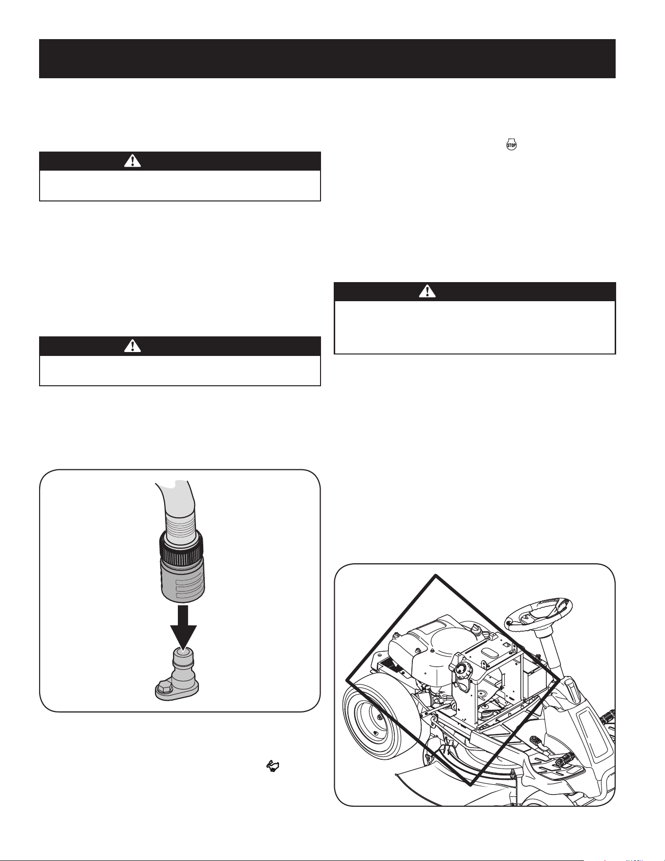
56
SERVICIO Y MANTENIMIENTO
8. Permanezca en la posición del operador con la plataforma enganchada
durante dos minutos como mínimo, permitiendo que la parte inferior de la
plataforma de corte se lave a fondo.
9. Mueva la PTO del tractor a la posición de desactivación (OFF).
10. Gire la llave de encendido a la posición STOP (detención) para apagar el
motor del tractor.
11. Desconecte el agua y retire el acoplador de la manguera desde el puerto de
agua que se encuentra en la superficie de la plataforma.
12. NOTA: En las plataformas de 50 y 54 pulgadas hay dos puertos de agua; uno a
cada lado de la plataforma.
13. Después de limpiar la plataforma con el sistema Smart Jet, regrese a
la posición del operador y active la PTO. Mantenga la plataforma en
funcionamiento durante dos minutos por lo menos para permitir que se
seque totalmente la parte inferior de la misma.
Limpieza del tractor
ADVERTENCIA
Si el tractor ha sido recientemente funcionar, el motor, el silenciador y
las superficies metálicas circundantes estarán calientes y pueden causar
quemaduras en la piel. Deje que el motor se enfríe durante al menos cinco
minutos la precaución para evitar quemaduras.
Su tractor debe limpiarse después de cada uso y bajo ciertas condiciones, es decir,
condiciones secas y/o situaciones de picado, de limpieza adicional puede ser
necesario.
Una de las mejores maneras de mantener su tractor funcionando de manera
eficiente y para reducir el riesgo de incendio es eliminar la acumulación de basura
con regularidad desde el tractor. Siga las recomendaciones a continuación y
póngase en contacto con su distribuidor autorizado con cualquier pregunta.
• Deje que la máquina se enfríe en un área abierta antes de la limpieza.
• No use agua en cualquier parte del tractor, excepto la parte inferior de la
plataforma de corte. Si lo hace, puede provocar daños en los rodamientos
para husillos del tractor, el sistema eléctrico y el motor, lo que lleva a fallas
prematuras. El uso de aire comprimido y / o soplador de hojas se ayudar a
mantener limpio el tractor.
• Clean bajo el capó. Colector de escape, alrededor de fusibles, todo el
cableado y arneses, tubo silenciador, escudo de silenciador, pantallas de
admisión del motor y las aletas de refrigeración, etc. Vea la Figure 2.
Figure 2
Después de la operación del tractor Cuidado
Después de cada operación del tractor, los siguientes procedimientos deben ser
implementados para extender la vida útil de su tractor y garantizar condiciones
seguras de operación.
PELIGRO
El incumplimiento de estas recomendaciones puede provocar lesiones graves
a sí mismo oa otros y puede causar daños en el tractor.
Limpieza de la parte inferior del piso
Deck Wash System (si viene equipado)
La plataforma de su tractor está equipada con un puerto de agua sobre su superficie
como parte del sistema de lavado de la plataforma.
Utilice el Smart Jet para quitar los recortes de césped de la parte inferior de la
plataforma e impedir la acumulación de sustancias químicas corrosivas. Realice los
siguientes pasos DESPUÉS DE CADA CORTE DE CÉSPED:
1. Dirija el tractor a una zona nivelada y despejada del césped, que se encuentre
suficientemente cerca de una canilla de agua al alcance de la manguera del jardín.
PRECAUCIÓN
Asegúrese de que el canal de descarga del tractor NO ESTÉ ORIENTADO EN LA DIRECCIÓN en que se
encuentran las personas, la casa, el garaje, los vehículos estacionados, etc.
2. Desconecte la toma de fuerza (PTO), aplique el freno de mano y detenga el motor.
3. Enrosque el acople de manguera (embalado con el Manual del Operador de
su tractor) en el extremo de la manguera de jardín.
4. Una el acople de la manguera al puerto de agua que se encuentra en la
superficie de la plataforma. Vea la Figure 1.
Figure 1
5. Abra el suministro de agua.
6. Mientras está sentado en la posición del operador del tractor, arranque el
motor y coloque la palanca del regulador en la posición FAST (velocidad
rápida).
7. Mueva la PTO del tractor a la posición de activación (ON).
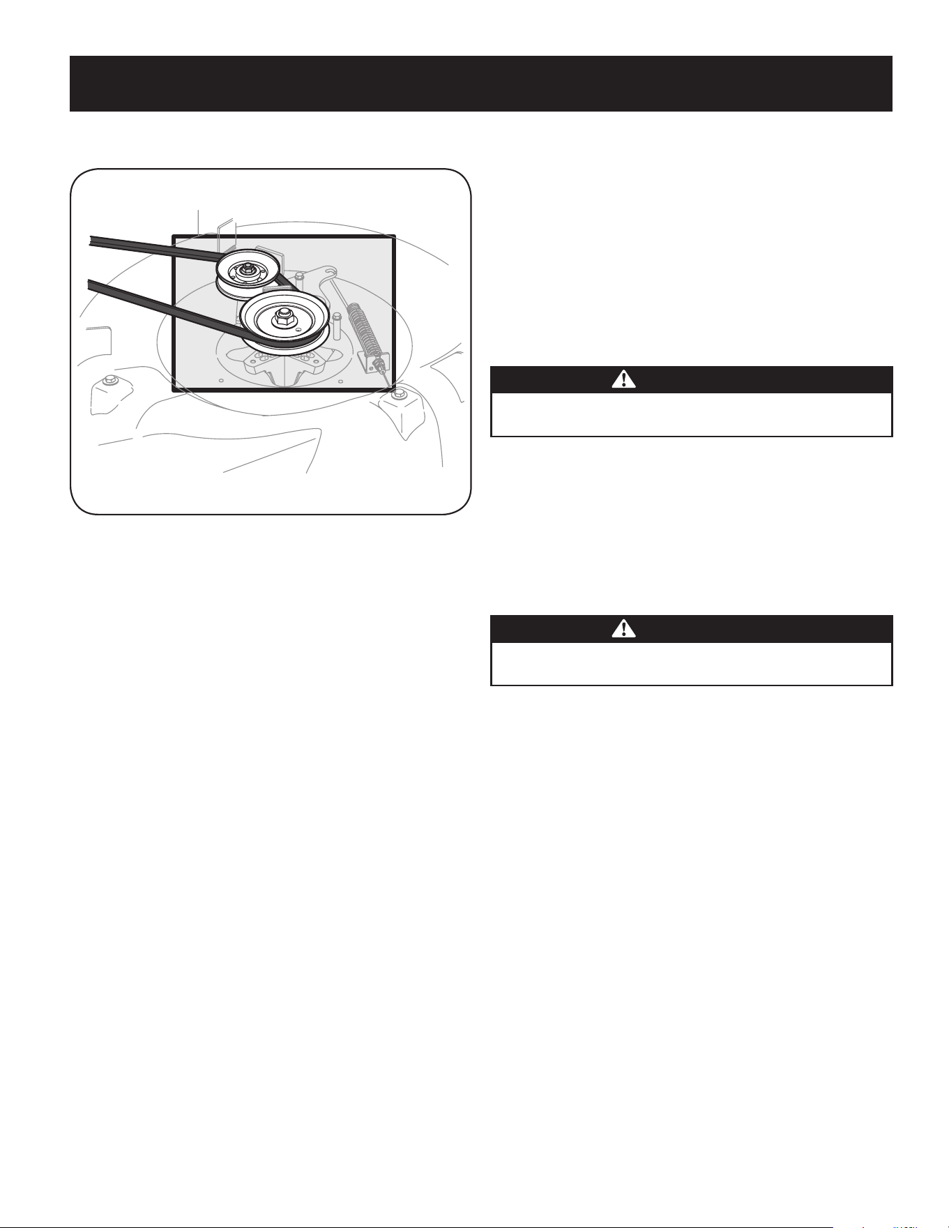
57
SERVICIO Y MANTENIMIENTO
Almacenamiento del tractor
• Deje que la máquina se enfríe en un área abierta antes de guardarlo.
• No estacione el tractor cerca de materiales inflamables (madera, tela o productos
químicos) o cualquier llama abierta u otra fuente potencial de ignición (horno,
calentador de agua o cualquier otro tipo de calentador).
• Retire todos los materiales combustibles desde el tractor antes de guardarla.
Cajas de carga vacíos, recogedores de hierba y contenedores.
• Siempre cerrar el flujo de combustible cuando almacenar o transportar si
tractor está equipado con un cierre de combustible.
• Compruebe el sistema de combustible (líneas, el tanque, tapa y accesorios)
con frecuencia grietas o fugas. Reparación y limpiar como sea necesario.
MANTENIMIENTO DEL MOTOR
ADVERTENCIA
Apague el motor antes de realizar el mantenimiento. Para evitar una puesta
en marcha accidental, desconecte la funda de la bujía.
IMPORTANTE: Si el motor debe inclinarse para transportar equipo o para inspec-
cionar o extraer pasto, mantenga el lado de la bujía del motor hacia arriba. Si la bujía
del motor se transporta o se inclina hacia abajo puede causar humo, problemas de
arranque, suciedad en la bujía o saturación con aceite del depurador de aire.
La inspección y los ajustes periódicos del motor son esenciales si se desea mantener
un alto nivel de desempeño. El mantenimiento regular también garantizará una
prolongada vida útil del motor. Los intervalos de mantenimiento requeridos y el tipo
de mantenimiento a ser realizado se describen en la tabla de la página precedente.
Siga los intervalos por hora o calendarios, lo que ocurra primero. Cuando se opera en
condiciones adversas es necesario llevar a cabo un mantenimiento más frecuente.
ADVERTENCIA
Si el motor ha estado funcionando, el silenciador estará muy caliente. Tenga
cuidado para no tocar el silenciador.
Servicio del aceite del motor
• Inspeccione el nivel de aceite regularmente.
• Asegúrese de que se mantenga el nivel de aceite correcto. Controle el aceite
cada cinco a diez horas de funcionamiento, antes de poner en marcha el motor.
Consulte Control del nivel de aceite en la sección Montaje.
Use solamente un aceite detergente de alta calidad cuya clasificación de servicio
API sea SF, SG, SH o SJ. Seleccione el grado de viscosidad SAE del aceite según
la temperatura de operación esperada. Consulte Gasolina y aceite en la sección
Ensamblado de este manual.
Drenaje del aceite
IMPORTANTE: Asegúrese de inspeccionar el motor sobre una superficie nivelada
y con el motor apagado. Drene el aceite mientras el motor esté caliente para
asegurar un drenaje rápido y completo.
Para drenar el aceite del cárter de motor de ciertos modelos de tractores, se adjunta
una manga de plástico para drenado de aceite junto con este Manual del Operador.
Para drenar el aceite, proceda de la siguiente manera:
14. Desenrosque el tapón de llenado de aceite y extraiga la varilla de nivel de
aceite del tubo de llenado.
15. Coloque el extremo pequeño de la manga de drenado en el cárter de aceite.
Vea la Figura 22.
16. Extraiga el tapón de drenado y vacíe el aceite en un contenedor apropiado,
con una capacidad no menor a 64 oz.
17. Incline el tractor ligeramente en dirección de un recipiente adecuado para
ayudar a drenar por completo todo el aceite del motor.
• Limpiar la parte superior de la plataforma de corte, bajo las sábanas de
husillo y área de la correa. Vea la Figure 3.
Figure 3
• Limpia alrededor y cerca de la transmisión, el eje y el área del ventilador. Vea
la Figure 3.
• Los residuos pueden acumularse en cualquier lugar en el tractor,
especialmente en superficies horizontales. Limpieza adicional puede ser
necesaria cuando la siega en condiciones secas o cuando acolchado.
• Fugas de combustible / derrames, fugas de aceite / derrames y el exceso
de lubricación también pueden convertirse en sitios de colecciones de
escombros. Inmediata reparación y limpieza de derrames de aceite o
combustible puede ayudar a reducir los riesgos de incendio.
• Además de limpiar el tractor, antes de manejar y almacenar, no intente cortar
inusualmente alto (10 “o superior), la hierba seca (por ejemplo, pasto) o pilas
de hojas secas. Hierba u hojas en seco pueden ponerse en contacto con los
gases de escape del motor y / o acumularse en la plataforma de corte en un
peligro de incendio.
Batería
Limpie la batería retirándola del tractor cortacésped y lavándola con bicarbonato de
sodio y una solución de agua. Si es necesario, raspe los bornes de la batería con un
cepillo de alambre para quitar los depósitos. Cubra los bornes y los cables expuestos
con grasa o vaselina para prevenir la corrosión.
La batería está sellada y no necesita mantenimiento. Los niveles de ácido no se
pueden controlar.
• Siempre mantenga limpios y libres de acumulación de elementos corrosivos
los cables y los bornes de la batería.
• Después de limpiar la batería y los bornes, aplique una capa delgada de
vaselina o grasa a ambos bornes.
• Siempre mantenga los capuchones de goma colocados sobre el borne positivo
para prevenir un cortocircuito.
Importante: Si por alguna razón extrae la batería, desconecte primero
el cable NEGATIVO (negro) de su borne y a continuación el cable POSITIVO
(rojo). Cuando vuelva a instalar la batería, conecte siempre primero el cable
POSITIVO (rojo) a su borne, y a continuación el cable NEGATIVO (negro).
Asegúrese que los cables estén conectados a los bornes correctos, ya que
si los cambia se podría invertir la polaridad y provocar un daño al sistema
alternador del motor.
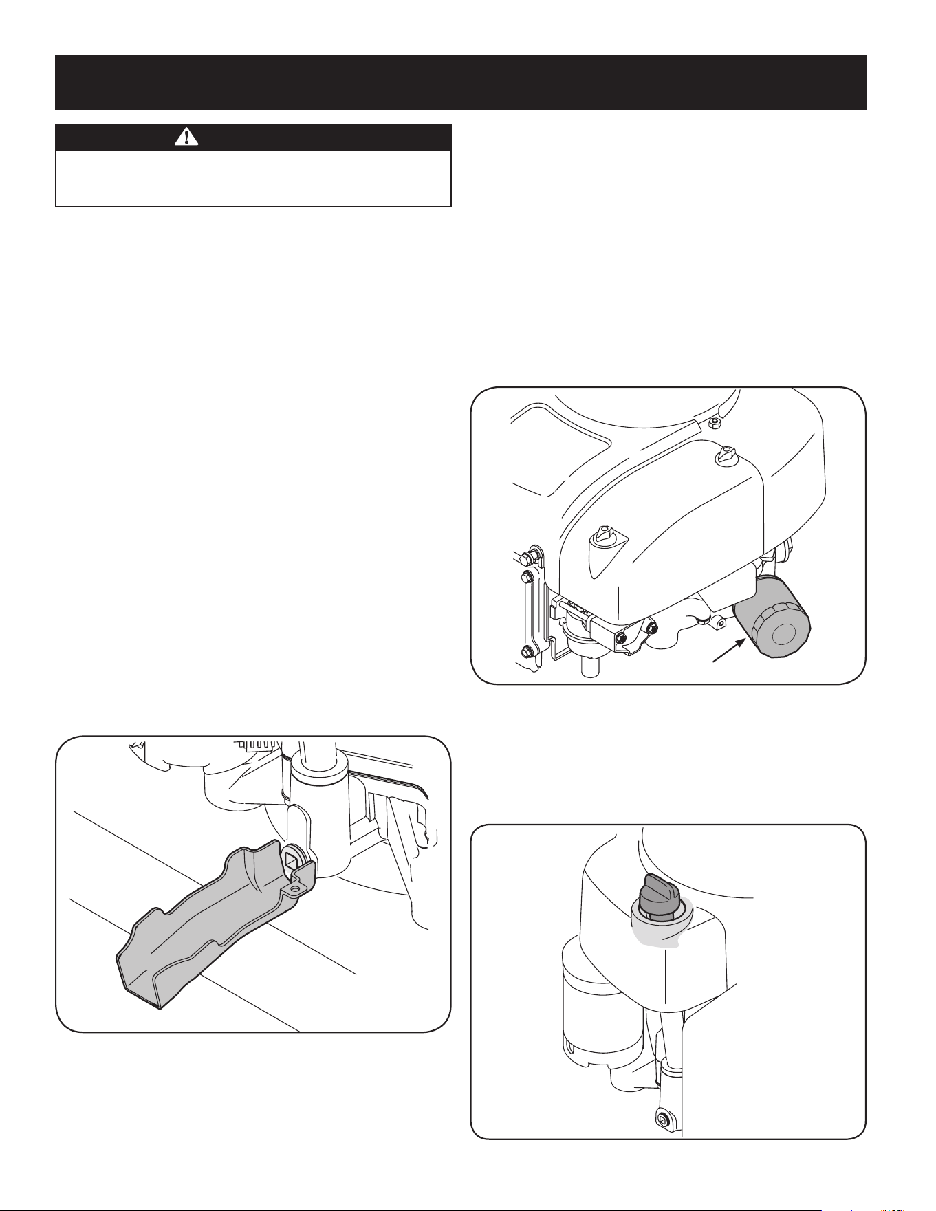
58
SERVICIO Y MANTENIMIENTO
Para reemplazar el filtro de aceite:
1. Drene el aceite como se indicó precedentemente en esta sección.
2. Extraiga el filtro de aire. Deseche el filtro viejo de manera adecuada.
3. Lubrique la junta del filtro nuevo con aceite limpio.
4. Coloque y gire el filtro de aceite manualmente hasta que la junta entre en
contacto con la superficie de sellado de la cubierta del cárter, luego ajuste el
filtro de aceite, 10-12 Nm (88.5-106.2 pulgada-libra), 1/2-3/4 de giro.
5. Agregue aceite como se indicó precedentemente.
6. Asegúrese de que la varilla de medición esté instalada.
7. Encienda y haga funcionar el motor. Compruebe si hay fugas.
8. Detenga el motor. Espere unos minutos y controle el nivel de aceite. Consulte
Control del nivel de aceite en la sección Montaje del presente manual.
Filtro de aceite
Figura 23
Procedimiento para agregar aceite
IMPORTANTE: Asegúrese de inspeccionar el motor sobre una superficie nivelada
y con el motor apagado.
1. Limpie alrededor de la tapa y el tubo de la varilla de medición con una tela
limpia para eliminar los residuos. Vea la Figura 24.
Figura 24
ADVERTENCIA
Antes de inclinar el motor o equipo para drenar el aceite, drene el
combustible del depósito haciendo funcionar el motor hasta que el
depósito de combustible esté vacío.
18. Realice el servicio del filtro de aceite como se indica posteriormente
en esta sección.
19. Si lo desea, realice el servicio del filtro de aceite como se indica posteriormente
en esta sección.
20. Vuelva a instalar el tapón de drenado y ajústelo firmemente, 12-14 Nm
(106.2-123.9 pulgada-libra).
21. Extraiga la manga de drenado de aceite del cárter de aceite. Vuelva a colocar
la varilla de nivel en el tubo de llenado de aceite y enrosque el tapón de
llenado en su lugar.
22. Vierta el aceite en el tubo de la varilla. No llene en exceso. Con un aceite
Cambiar el filtro de la cantidad elevada de aceite para este motor es 1700 ml
(57,48 fl-oz).
23. Instalar la varilla medidora y gire a la posición de bloqueo antes de comenzar
24. motor.
25. Encienda el motor. Deje de correr durante unos segundos y luego apáguelo el
motor.
26. Revise el nivel de aceite. Vea la sección Comprobación del nivel de aceite.
IMPORTANTE: El aceite usado del motor puede causar cáncer de piel si entra en
contacto con la piel de manera reiterada y por períodos prolongados. Si bien esto
es improbable a menos que manipule aceite usado todos los días, sin embargo es
recomendable lavarse bien las manos con agua y jabón inmediatamente después
de haber manipulado aceite usado.
NOTA: Elimine el aceite del motor usado de la manera que sea compatible con el
medio ambiente. Sugerimos que lo coloque en un recipiente sellado y lo lleve a la
estación de servicio local para su recuperación. No lo tire a la basura ni lo vierta en
el drenaje o en el suelo.
Figura 22
Reemplazo del filtro de aceite
Este motor está equipado con un filtro de aceite a rosca que debe reemplazarse
cada vez que se realiza un cambio de aceite, en cada estación o cada 50 horas.
Consulte la Figura 23.
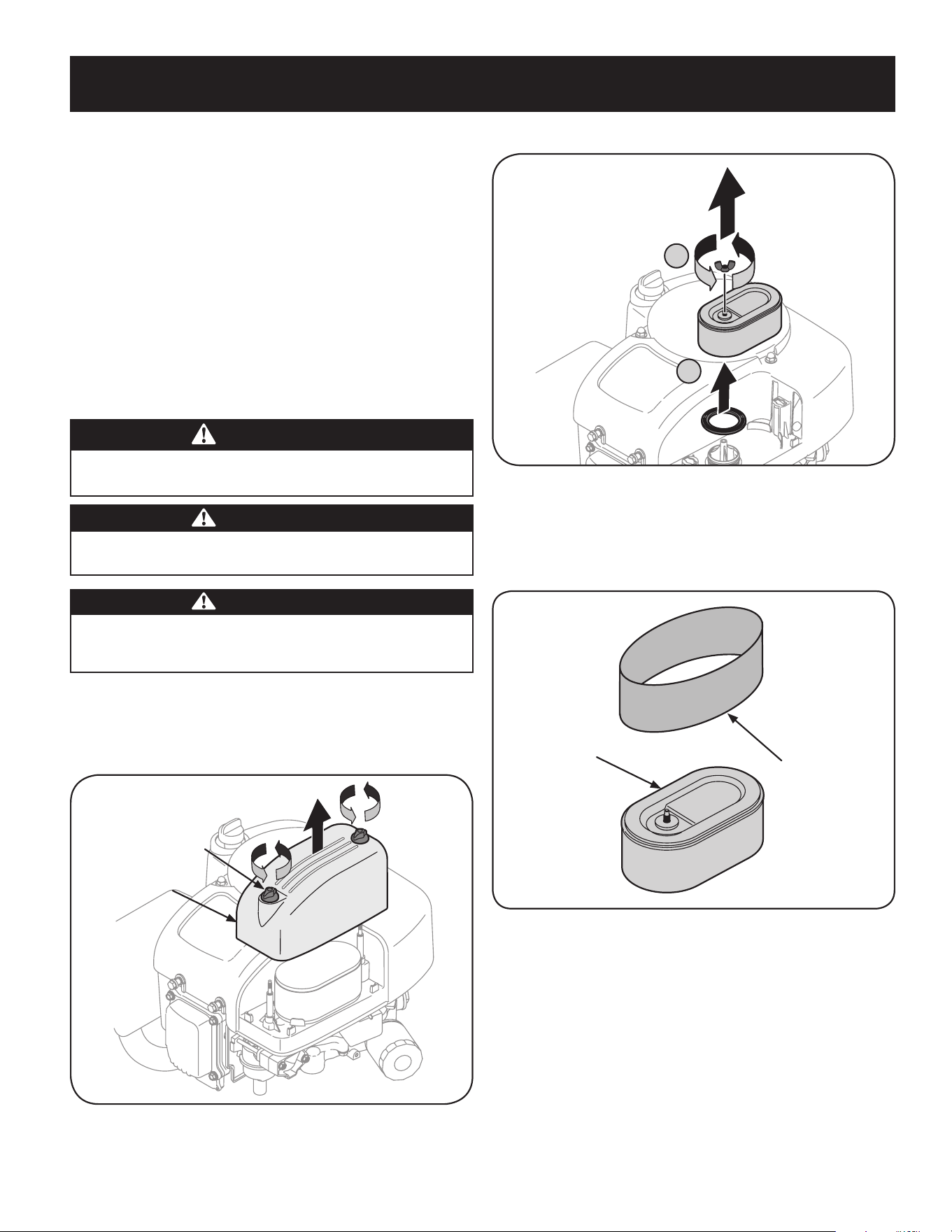
59
SERVICIO Y MANTENIMIENTO
2. Retire el tornillo de mariposa (A). Vea la Figura 26.
A
B
Figura 26
3. Tire hacia arriba y retire el filtro de aire y el sello de base (B). Vea la Figura 26.
4. Retire el prefiltro de espuma de alrededor del filtro de aire de papel. Vea la
Figura 27. Reemplace el elemento de papel si está sucio o dañado. Limpie el
elemento de espuma o reemplácelo si está dañado.
Filtro de
aire
Pre-filtro
Figura 27
5. A fin de limpiar el elemento de espuma, lávelo con detergente líquido suave
y agua. Apriete u oprima el elemento de espuma para enjuagar la suciedad
y el agua. No lo retuerza; si lo hace, podría dañar o rasgar el elemento de
espuma. Permita que se seque bien antes de usarlo. NO lubrique el elemento
de espuma.
6. Sujete el filtro de aire nuevo con el elemento de espuma, para lo cual debe
alinear el orificio del filtro de aire con el colector de admisión. Vea la Figura 28.
Asegure con el tornillo de mariposa.
2. Saque la varilla de medición del nivel del aceite y límpiela con una tela.
3. Vierta aceite dentro del tubo de la varilla de medición. No llene
excesivamente. Con un cambio de filtro de aceite la cantidad de aceite de alto
nivel para este motor es de 1700 ml (57.48 onzas líquidas).
4. Coloque la varilla de medición y gírela hasta la posición en que queda trabada
antes de arrancar el motor.
5. Arranque el motor. Déjelo en marcha durante unos segundos y luego
apague el motor.
6. Controle el nivel de aceite. Consulte Control del nivel de aceite en la sección
Montaje del presente manual.
Mantenimiento del filtro de aire
Los filtros de papel no se pueden limpiar y se deben reemplazar cada 100 horas
de funcionamiento; con mayor frecuencia si se utilizan en lugares donde abunda
el polvo.
ADVERTENCIA
Nunca use gasolina o solventes de punto de encendido bajo para limpiar el
elemento del filtro de aire. Podría producirse un incendio o explosión.
PRECAUCIÓN
No use aire presurizado ni disolvente para limpiar el cartucho purificador
de aire.
ADVERTENCIA
Si no se instalan correctamente los filtros o las cubiertas, las explosiones
del carburador pueden causar lesiones graves o la muerte. No intente
hacer arrancar el motor cuando no están colocados.
IMPORTANTE: Nunca opere el motor sin el filtro de aire. Resultará en desgaste
rápido del motor.
1. Desenrosque los tornillos de orejetas y quite la cubierta del filtro de aire.
Vea la Figura 25.
Tapa del filtro
de aire
Tornillo de
orejetas
Figura 25
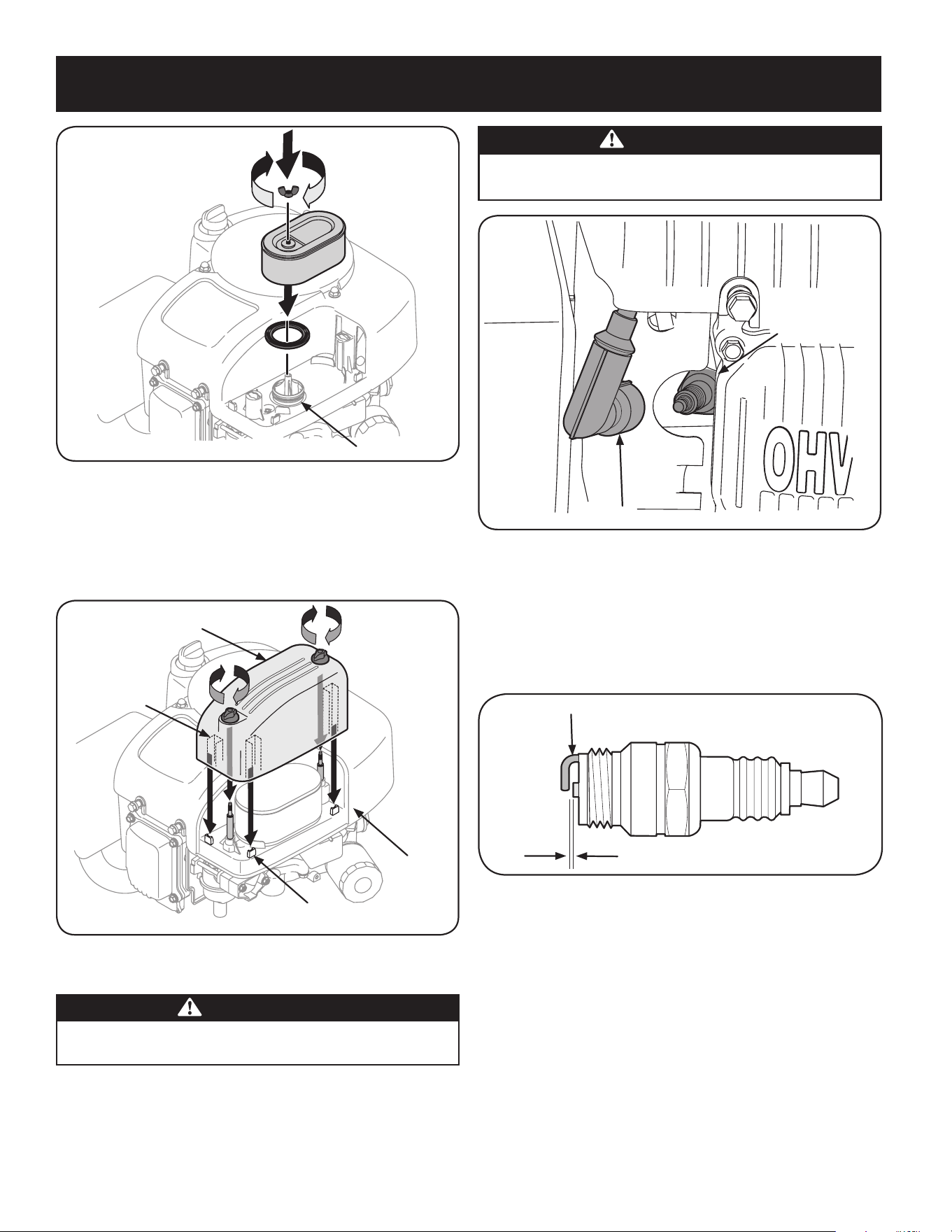
60
SERVICIO Y MANTENIMIENTO
ADVERTENCIA
Si el motor ha estado funcionando, el silenciador estará muy caliente.
Tenga cuidado para no tocar el silenciador.
Bujía de
encendido
Funda de bujía
Figura 30
2. Inspeccione visualmente la bujía. Elimine la bujía si presenta mucho desgaste,
o si el aislante está agrietado o astillado. Limpie la bujía con un cepillo de
alambre si se va a reutilizar.
3. Mida la separación de bujía con un calibrador. Corrija de ser necesario
torciendo el electrodo lateral. Vea la Figura 31. La separación debe establecerse
para que quede entre 0.024-0.031 pulg.
Electrodo
0.024-0.031 in.
Figura 29
4. Verifique que la arandela de la bujía esté en buenas condiciones y enrosque la
bujía hacia adentro manualmente para evitar el enrosque cruzado.
5. Una vez que la bujía está asentada en su lugar, ajuste con una llave para bujía
para comprimir la arandela.
NOTA: Cuando instale una bujía nueva, apriete 1/2 de vuelta una vez que la
bujía se encuentra colocada en su lugar para comprimir la arandela. Cuando
vuelva a colocar una bujía usada, apriete 1/8 - 1/4 de giro después de que la
bujía se asienta para comprimir la arandela.
IMPORTANTE: La bujía debe estar firmemente asegurada. Si la bujía no está
bien asegurada puede calentarse mucho y dañar el motor.
Mantenimiento del filtro de combustible
Colector de admisión
Figura 28
7. Sujete la cubierta del filtro de aire comprobando que queden alineadas
las nervaduras plásticas de la cubierta con los dispositivos plásticos de la
cubierta del filtro de aire. Vea la Fig. 29. Gire los tornillos de orejetas en el
sentido de las agujas del reloj hasta que queden ajustados. Controle si hay
problemas de alineación.
Nervadura
plástica
Cubierta
Dispositivo
plástico
Tapa del filtro
de aire
Figura 29
Mantenimiento de bujía
ADVERTENCIA
NO pruebe la chispa si no está la bujía de encendido. NO dé arranque al motor si no
está la bujía de encendido.
Para asegurarse de que el motor funcione bien, la bujía debe tener una separación
correcta y debe estar libre de depósitos.
1. Retire la funda de bujía y utilice una llave para bujías para extraer la bujía. Vea
la Figura 30.

61
SERVICIO Y MANTENIMIENTO
ADVERTENCIA
La gasolina y el vapor de gasolina son sumamente inflamables y
explosivos. El fuego y las explosiones pueden causar quemaduras graves
y también la muerte.
• Mantenga la gasolina alejada de chispas, llamas expuestas, llamas piloto,
calor, y otras fuentes de ignición.
• Verifique frecuentemente las líneas de combustible, el tanque, el tapón, y los
accesorios buscando rajaduras o pérdidas. Reemplace de ser necesario.
• Antes de reemplazar el filtro de combustible, drene el depósito de combustible
como se indica en Para drenar el combustible.
• No drene el combustible cuando el motor está caliente. Permita que el motor
se enfríe bien. Drene el combustible dentro de un recipiente aprobado y al aire
libre, lejos de cualquier llama expuesta.
• Drene un volumen de combustible grande desde el depósito, desconectando
la línea de combustible del filtro de combustible en línea que se encuentra
cerca del motor.
• Retire la línea de combustible del lado en línea (lado orientado al depósito
de combustible) del filtro de combustible.
• Los repuestos deben ser los mismos y se deben instalar en la misma posición
que las piezas originales.
• Si se derrama combustible, espere hasta que se evapore antes de encender
el motor.
• Antes de reemplazar el filtro de combustible, drene el depósito de combusti-
ble. De lo contrario, el combustible puede gotear y causar un incendio
o una explosión.
Para drenar el combustible:
1. Ubique el filtro de combustible, que pasa del lado izquierdo del motor, entre
el tanque de combustible y el carburador, y puede estar sujeto al motor con
una tira de unión. Corte la tira, si la hay, luego sujete la abrazadera en línea
del filtro de combustible con un par de pinzas, deslice la abrazadera hacia
arriba por la línea de combustible. Saque la línea de combustible del filtro y
coloque el extremo abierto de la línea en un recipiente aprobado para drenar
el combustible.
Para cambiar el filtro de combustible:
2. Utilice pinzas para apretar las lengüetas de la otra abrazadera (el lado fuera
de línea del filtro de combustible), luego deslice la abrazadera alejándola del
filtro de combustible. Gire y tire de la línea de combustible del filtro.
Vea la Figura 32.
3. Verifique que las líneas de combustible no tienen rajaduras o pérdidas.
Reemplace de ser necesario.
4. Reemplace el filtro de combustible por un filtro de recambio de equipo
original. Llame a 1-888-331-4569 para comprar el filtro de repuesto del equipo
original.
5. Sujete las líneas de combustible con las abrazaderas.
El filtro de combustible no se puede limpiar y se debe reemplazar cada 100 horas de
funcionamiento; con mayor frecuencia si se utiliza con gasolina vieja.
Filtro de
combustible
Línea de
combustible
Lengüeta
Abrazadera
Figura 32
Limpie el motor
Si el motor ha estado funcionando, déjelo enfriar durante por lo menos media hora
antes de limpiarlo. Retire periódicamente la suciedad acumulada en el motor.
Limpie las aletas de refrigeración del motor cada 25 horas. Limpie con un cepillo
o aire comprimido.
IMPORTANTE: No rocíe el motor con agua para limpiarlo porque el agua podría con-
taminar el combustible. Con una manguera de jardín o equipo de lavado a presión
también puede forzar agua dentro del filtro de aire o la abertura del silenciador. El
agua en el filtro de aire embeberá el elemento de papel, y el agua que pasa a través
del elemento o silenciador puede ingresar en el cilindro, causando daño.
ADVERTENCIA
La acumulación de residuos alrededor del silenciador podría producir un
incendio. Inspecciónelo y límpielo antes de cada uso.
EXTRACCIÓN DE LA PLATAFORMA DE CORTE
Para extraer la plataforma de corte, proceda de la siguiente manera:
1. Coloque la palanca de la toma de fuerza (PTO) (enganche de cuchilla) en la
posición OFF (desconectada) y ponga el freno de mano.
2. Baje la plataforma colocando la palanca de elevación de la plataforma
dentro de la muesca inferior del guardabarros derecho.
3. Extraiga la correa de alrededor de la polea de la PTO del tractor.
Vea la Figura 33.
ADVERTENCIA
Evite las lesiones por compresión. Al extraer la correa, no coloque nunca
los dedos en el resorte intermedio o entre la correa y una polea.
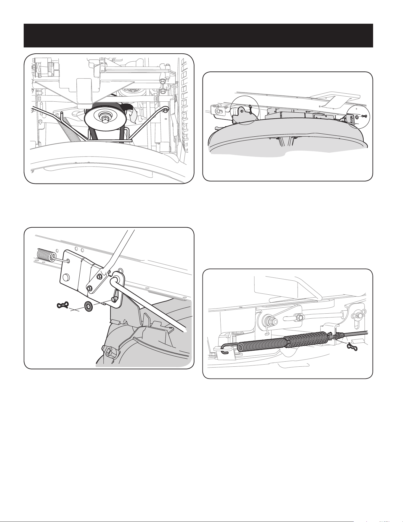
62
SERVICIO Y MANTENIMIENTO
5. Extraiga los pasadores de chaveta con unión curva que aún están sujetando
la unidad, como se indica en la Figura 35.
Figura 35
NOTA: Los pasadores de chaveta con unión curva se deben volver a colocar de
arriba hacia abajo.
6. Mueva la palanca de elevación de la plataforma dentro de la muesca
superior del guardabarros derecho para levantar los brazos de elevación de la
plataforma y sacarlos del camino.
7. Desconecte el cableado en espiral del interruptor de seguridad de la plataforma.
8. Extraiga con cuidado el cable de la PTO de la parte posterior de la plataforma
de corte retirando el pasador de chaveta con unión curva que lo sujeta. Retire
el resorte del soporte de polea loca de la plataforma. Vea la Figura 36.
Figura 36
9. Deslice suavemente la plataforma de corte (desde el lado izquierdo) hacia
afuera desde la parte inferior del tractor.
Cambio de la correa de la plataforma
NOTA: Se puede cambiar la correa de la plataforma sin desinstalar la plataforma de
corte del tractor; sin embargo, resulta mucho más fácil extraer primero la platafor-
ma, cambiarle la correa y luego volver a instalar la plataforma de corte.
Para cambiar la correa de la plataforma de corte, proceda de la siguiente manera:
1. Lo más fácil es cambiar la correa de la plataforma extrayendo primero la
plataforma de corte como se indica previamente en esta sección. Omita este
paso si decide cambiar la correa de la plataforma sin extraer la plataforma de
corte de la unidad. De lo contrario, extraiga la plataforma de corte ahora.
2. Si va a cambiar la correa de la plataforma con la plataforma de corte instalada
en la unidad, baje la plataforma de corte a la posición de corte más baja.
3. Extraiga la correa de alrededor de la polea de transmisión de la PTO de la
Figura 33
4. Extraiga el pasador de chaveta con unión curva y la arandela plana del
conjunto de elevación de la plataforma y guárdelo para volver a colocarlo
posteriormente. Vea la Figura 34.
Figura 34
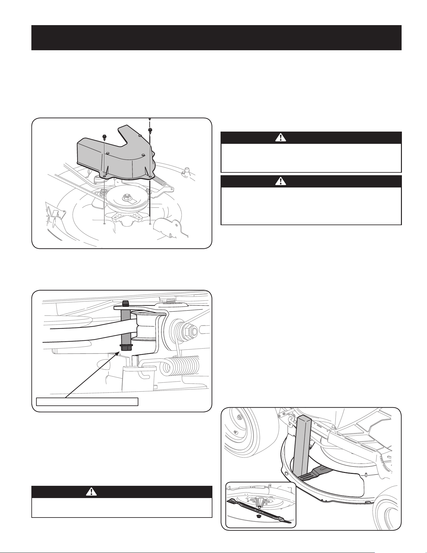
63
SERVICIO Y MANTENIMIENTO
unidad como se indica en la Figura 33. Simplemente deje rodar un lado de la
correa para que salga de la polea y luego debe seguir sacándola todo alrededor
de la polea hasta que se suelta de la polea.
4. Lleve la correa hacia el frente de la unidad, jalándola a través y hacia afuera de
la ménsula del guardacorrea, como se indica en la Figura 33.
5. Extraiga la cubierta de la correa de la plataforma, para lo cual deberá retirar los
tres pernos hexagonales que la sujetan. Vea la Figura 37.
Figura 37
6. Extraiga el espaciador del guardacorrea extrayendo los pernos hexagonales
que la sujetan. Vea la Figura 38.
Perno hexagonal del guardacorrea
Figura 38
7. Cambie la correa, luego vuelva a instalar todos los componentes que extrajo
siguiendo el orden inverso, comenzando por la polea loca y terminando por la
cubierta de la correa.
8. Pase la correa de la plataforma a través de la ménsula del guardacorrea y
colóquela alrededor y sobre la polea de transmisión de la PTO, como se indica
en la Figura 31.
NEUMÁTICOS
ADVERTENCIA
Nunca exceda la presión máxima de inflado que se indica en los laterales de
los neumáticos.
La presión operativa recomendada para los neumáticos es:
y Aproximadamente 10 psi para los neumáticos traseros
y Aproximadamente 14 psi para los neumáticos delanteros
IMPORTANTE: Consulte los laterales de las ruedas para conocer con exactitud
la presión máxima en psi recomendada por el fabricante. No los infle en exceso.
Una presión de neumáticos despareja podría hacer que la plataforma no corte el
césped parejo.
CUCHILLA DE CORTE
ADVERTENCIA
Apague el motor y extraiga la llave de contacto antes de retirar las cuchil-
las de corte para afilarlas o reemplazarlas. Proteja sus manos utilizando
guantes reforzados cuando sujete las cuchillas.
ADVERTENCIA
Inspeccione periódicamente la cuchilla y/o el husillo en busca de
rajaduras o daños, especialmente después de golpear un objeto extraño.
No opere la máquina hasta después de haber reemplazado los componen-
tes dañados.
Para retirar la cuchilla, haga lo siguiente.
NOTA: Puede resultar más fácil cambiar la cuchilla empezando primero por
extraer la plataforma de la parte inferior del tractor, (consulte la sección
Extracción de la plataforma de corte en partes anteriores de esta sección);
luego voltee con delicadeza la plataforma para dejar al descubierto su parte
inferior. Sin embargo, es posible cambiar la cuchilla sin sacar la plataforma
del tractor. Si se intenta cambiar la cuchilla sin sacar la plataforma del tractor,
primero se debe mover la palanca de elevación de la plataforma hasta su
posición de corte más elevada.
1. Extraiga la clavija de abono, el canal de la plataforma o el canal de la
embolsadora, si viene equipado, dejando a la vista la abertura del canal
de la plataforma.
2. Use un bloque de madera o un 2 x 4, insértelo dentro de la abertura de la
plataforma y haga girar la cuchilla hasta que la madera haga cuña entre la
abertura de la plataforma y la cuchilla de corte, como se indica en la Figura 39.
3. Extraiga la tuerca de brida hexagonal que asegura la cuchilla al montaje del
husillo y retire la cuchilla. Vea el recuadro de la Figura 39.
NOTA: El husillo de la plataforma tiene una rosca normal. Para aflojarlo, rote
la tuerca de seguridad con brida en sentido contrario a las agujas del reloj.
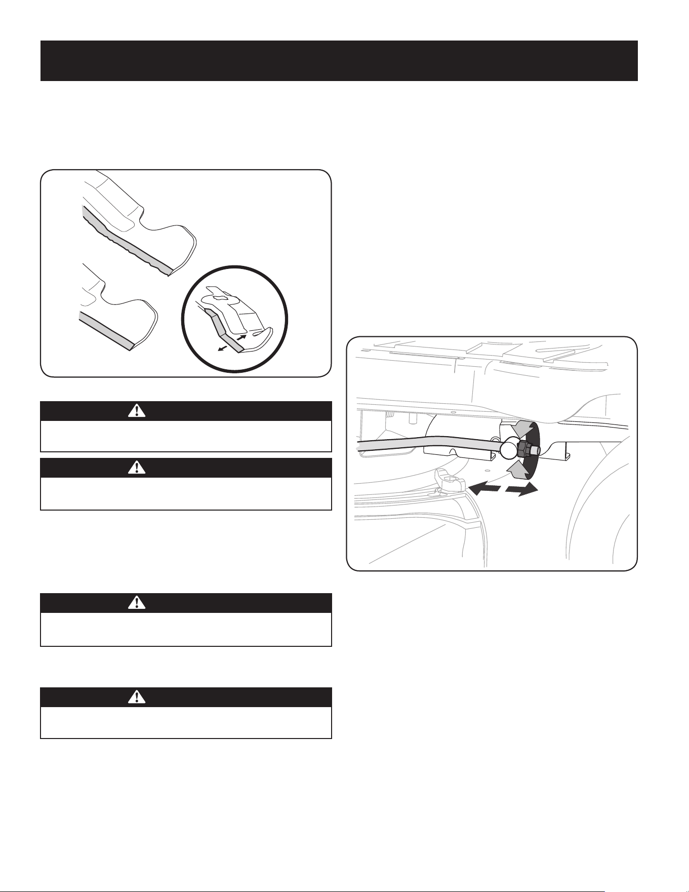
64
SERVICIO Y MANTENIMIENTO
Figura 39
4. Para afilar las cuchillas de corte de forma adecuada, extraiga cantidades
iguales de metal de ambos extremos de las cuchillas a lo largo de los bordes
cortantes, paralelo al borde de caída y a un ángulo de 25° a 30°. Afile siempre
cada borde de las cuchillas de corte de forma pareja para mantener un
equilibrio adecuado entre las mismas. Vea la Figura 40.
Figura 40
PRECAUCIÓN
Si el borde de corte de la cuchilla ha sido afilado previamente o si existe
una separación de metal, reemplace las cuchillas por otras nuevas.
ADVERTENCIA
Una cuchilla mal equilibrada causará exceso de vibración y puede dañar
el tractor y/o causar lesiones personales.
5. Pruebe el equilibrio de la cuchilla usando un compensador de cuchillas.
Afile el metal del lado pesado hasta que quede bien equilibrada.
NOTA: Cuando reemplace la cuchilla, asegúrese de instalarla con el lado
marcado “Bottom” (inferior) (o con el lado que posee un número de pieza
estampado) mirando al piso cuando la cortadora de césped está en posición
de operación.
PRECAUCIÓN
Utilice una llave de torsión para ajustar la tuerca de brida hexagonal del
husillo de la cuchilla entre 70 y 90 pies-libras.
AJUSTES
ADVERTENCIA
Nunca intente hacer ajustes mientras el motor está en marcha, excepto
cuando así lo especifica el manual del operador.
Nivelación de la plataforma
NOTA: Controle la presión de neumáticos del tractor antes de realizar cualquier nive-
lación de la plataforma. Consulte Neumáticos en la sección Servicio y mantenimiento
de este manual para obtener más información sobre la presión de los neumáticos.
Nivelación frontal-posterior
Es posible ajustar la inclinación de la plataforma de corte. El frente de la plataforma
debe estar entre 0” (al ras) y 1/4” más bajo que la parte posterior de la plataforma.
De ser necesario, realice un ajuste de la siguiente manera:
1. Con el tractor estacionado sobre una superficie firme y nivelada, ubique la
palanca de elevación de la plataforma en la posición media (3) y rote la cuchilla
de manera que quede alineada con el frente y la parte posterior del tractor.
2. Mida la distancia desde la parte delantera de la punta de la cuchilla hasta
el piso, y desde la parte posterior de la punta de la cuchilla hasta el piso. La
primera medición debe ser entre 0” (al ras) y 1/4” menor que la segunda.
Determine la distancia aproximada necesaria para un ajuste adecuado y, de ser
necesario, siga con el paso siguiente.
3. Ubique la tuerca de seguridad con brida en el extremo frontal de la varilla
de elevación de la PTO. Vea la Figura 41.
• Apriete la tuerca de seguridad con brida para levantar la parte delantera
de la plataforma;
• Afloje la tuerca de seguridad con brida para bajar la parte delantera
de la plataforma.
Figura 41
AJUSTE DEL ASIENTO
Consulte en la sección Montaje de este manual las instrucciones para el ajuste
del asiento.

65
SERVICIO Y MANTENIMIENTO
AJUSTE DEL FRENO DE MANO
ADVERTENCIA
Nunca intente ajustar los frenos con el motor en marcha. Desenganche siempre
la PTO (palanca de enganche de cuchilla), mueva la palanca de cambios a la
posición neutral, pare el motor y retire la llave, para evitar que alguien encienda
accidentalmente el motor.
Si el tractor no se detiene por completo cuando se presiona totalmente el pedal de
embrague-freno, o si las ruedas traseras del tractor pueden rodar con el freno de
mano colocado, el freno necesita un ajuste. Comuníquese con el Centro de servicio de
reparaciones más cercano para que le hagan un servicio a los frenos.
Para ubicar el Centro de servicio de reparaciones y piezas más cercano
o para programar el servicio de mantenimiento o reparación, comuníquese
al teléfono 1-888-331-4569.
CAMBIO DE LA CORREA DE TRANSMISIÓN
NOTA: Para cambiar la correa de transmisión del tractor, se deben retirar varios
componentes y se requieren herramientas especiales (es decir, llave de impacto/ aire).
Comuníquese con el Centro de servicio de reparaciones y piezas más cercano para que
le hagan un servicio a la correa de transmisión.
Para ubicar el Centro de servicio de reparaciones y piezas más cercano, llame al
1-888-331-4569.
SILENCIADOR
ADVERTENCIA
La temperatura del silenciador y de las áreas cercanas del motor puede superar los
150˚F (65˚C). Evite el contacto con estas áreas.
• Inspeccione periódicamente el silenciador y reemplácelo si es necesario. Los
repuestos del silenciador deben ser los mismos y se deben instalar en la misma
posición que las piezas originales.
AJUSTE DEL CARBURADOR
• El carburador de este motor no es regulable.
BATERÍA
¡ADVERTENCIA Proposición 65 de California! Los bornes de la batería y los accesorios
afines contienen plomo y compuestos de plomo, sustancias químicas que según lo
establecido por el Estado de California causan cáncer y daños en el sistema reproduc-
tivo. Lávese las manos después de estar en contacto con estos componentes.
PRECAUCIÓN
Si extrae la batería, desconecte primero el cable NEGATIVO (negro) de su
borne y a continuación el cable POSITIVO (rojo). Cuando vuelva a instalar
la batería, conecte siempre primero el cable POSITIVO (rojo) a su borne,
y a continuación el cable NEGATIVO (negro).
La batería está sellada y no necesita mantenimiento. Los niveles de ácido no se
pueden controlar.
• Siempre mantenga limpios y libres de acumulación de elementos corrosivos los
cables y los bornes de la batería.
• Después de limpiar la batería y los bornes, aplique una capa delgada de
vaselina o grasa a ambos bornes.
• Siempre mantenga los capuchones de goma colocados sobre el borne positivo
para prevenir un cortocircuito.
Retrait de la batterie
1. Localisez la batterie sur le côté gauche de la tondeuse autoportée.
2. Retirez la vis hexagonale de rondelle de fixation du serre-flan tige de la
batterie au châssis. Voir Figure 42.
vis hex rondelle
Batterie Maintenir vers
le bas Rod
plateau de
batterie
Figure 42
3. Avec la tige de retenue des batteries retiré, retirez la batterie du bac de
batterie.
4. Pour réinstaller la batterie, placez-le dans le bac de la batterie et fixer en
place avec la tige de retenue batterie et vis hex de rondelle. Voir Figure 42.
IMPORTANTE: Si quita la batería por cualquier razón, desconecte primero el cable
NEGATIVO (negro) de su terminal y a continuación el cable POSITIVO (rojo). Cuando
vuelva a instalar la batería, conecte siempre primero el cable POSITIVO (rojo) a su
borne, y a continuación el cable NEGATIVO (negro). Asegúrese que los cables estén
conectados a los bornes correctos, ya que si los cambia se podría invertir la polaridad
y provocar un daño al sistema alternador del motor.
Limpieza de la batería
Limpie la batería retirándola del tractor y lavándola con bicarbonato de sodio y
solución de agua. Si es necesario, raspe los bornes de la batería con un cepillo de
alambre para quitar los depósitos. Cubra los bornes y los cables expuestos con grasa
o vaselina para prevenir la corrosión.
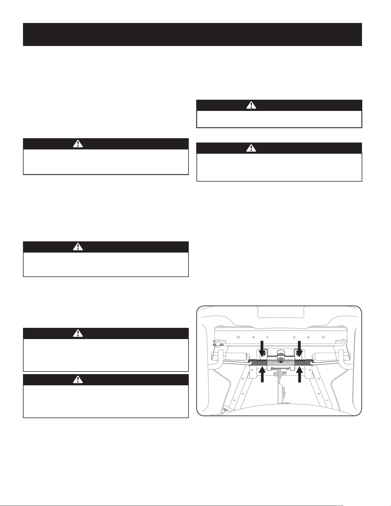
66
SERVICIO Y MANTENIMIENTO
Desperfectos de la batería
Algunas causas comunes de falla de la batería son:
• Activación inicial incorrecta
• Sobrecarga
• Congelamiento
• Carga insuficiente
• Corrosión en las conexiones
Estas fallas NO están cubiertas por la garantía de su tractor.
ARRANQUE CON CABLES DE PUENTE
ADVERTENCIA
Nunca arranque una batería dañada o congelada con conexiones en
puente. Asegúrese de que los vehículos no se toquen y los motores están
apagados. No permita que las pinzas de los cables se toquen.
1. Conecte el cable positivo (+) al borne positivo (+) de la batería descargada
de su tractor.
2. Conecte el otro extremo del cable al borne positivo (+) de la batería con carga.
3. Conecte el segundo cable negativo (–) al borne (–) de la batería cargada.
4. Conecte el otro extremo del cable negativo al bloque del motor del tractor,
alejado de la batería. Acople a una parte sin pintura para asegurarse de que
haya una buena conexión.
ADVERTENCIA
Si la batería con carga está instalada en el vehículo (es decir automóvil,
camión) NO ponga en marcha el motor del vehículo cuando arranque su
tractor con conexiones en puente.
5. Arranque el tractor (según las instrucciones de la sección Funcionamiento
de este manual).
6. Coloque el freno de mano del tractor antes de sacar los cables de conexión en
puente, en orden inverso de conexión.
DURACIÓN
ADVERTENCIA
Al cargarse, las baterías emiten un gas que puede causar explosiones.
Cargue la batería en un área bien ventilada y manténgala alejada de una
llama expuesta o piloto, como los de los calentadores de agua, calefacto-
res de ambiente, hornos, secadores de ropa y otros aparatos a gas.
PRECAUCIÓN
Cuando cargue la batería de su tractor, utilice únicamente un cargador
diseñado para baterías de plomo-ácido de 12V. Lea el manual del
operador del cargador de la batería antes de cargar la batería de su
tractor. Siempre siga las instrucciones y tenga en cuenta las advertencias.
Si su tractor no se ha utilizado durante un período de tiempo prolongado, cargue la
batería de la siguiente manera:
1. Ajuste el cargador de batería para que produzca un máximo de 10 amperios.
Si su cargador de batería es automático, cargue la batería hasta que el cargador
indique que se ha completado la carga. Si el cargador no es automático, cargue
durante ocho horas como mínimo.
FUSIBLE
En el mazo de cables de su tractor está instalado un fusible de 15 amperios, para proteger el
sistema eléctrico del tractor de los daños causados por exceso de amperaje.
Si el sistema eléctrico no funciona, o el motor de su tractor no arranca, verifique primero
que el fusible no se haya quemado. Se puede encontrar debajo del guardabarros en el
lado izquierdo de la unidad, en el mazo de cables justo encima de la batería.
ADVERTENCIA
Para el reemplazo utilice siempre un fusible con la misma capacidad de
amperaje.
LUBRICACIÓN
ADVERTENCIA
Antes de realizar tareas de lubricación, reparación o inspección, siempre
desconecte la PTO (palanca de enganche de cuchilla), mueva la palanca
de cambios a la posición neutral, ponga el freno de mano, pare el motor y
retire la llave, para evitar que alguien encienda accidentalmente el motor.
Puntos de pivote y varillaje
Lubrique todos los puntos de pivote del sistema de impulsión, el freno de mano
y el varillaje de elevación al menos una vez por temporada con aceite ligero.
Ruedas traseras
Las ruedas traseras se deben sacar de los ejes una vez por temporada. Lubrique bien
los ejes y las llantas con una grasa multiusos antes de reinstalarlos.
Ejes delanteros
Cada extremo de la barra de pivote delantera del tractor puede estar equipado
con un accesorio de engrasado. Lubrique con pistola de grasa cada 25 horas de
funcionamiento del tractor.
Cremallera y piñón de dirección
Una vez por temporada, o cada 25 horas de funcionamiento, será necesario lubricar
el mecanismo de cremallera y piñón de dirección que está ubicado debajo del frente
de la unidad. Mediante el uso de grasa para automóviles estándar, engrase el frente
y la parte posterior de la cremallera de dirección, como se indica en la Figura 43.
Figura 43
LIMPIEZA DEL MOTOR Y DE LA PLATAFORMA
Si se derrama combustible o aceite sobre la máquina, debe limpiarse de inmediato.
NO permita que se acumulen desechos alrededor de las aletas de refrigeración del
motor ni en ninguna otra parte de la máquina.
IMPORTANTE: NO se recomienda el uso de una lavadora de presión para limpiar
el tractor. Puede dañar los componentes eléctricos, los husillos, las poleas, los
rodamientos o el motor.

67
ALMACENAMIENTO FUERA DE TEMPORADA
PREPARACIÓN DEL MOTOR
IMPORTANTE: El combustible que queda en el tanque cuando hace
calor se deteriora y ocasiona graves problemas de encendido.
PRECAUCIÓN
La no utilización de un aditivo de combustible de estabilización o
totalmente en marcha el motor hasta que se quedan sin combustible
antes de su almacenamiento fuera de temporada puede resultar
en daños al carburador del motor. Daños posteriores no estarían
cubiertos por la garantía del fabricante.
Motores se almacena entre 30 y 90 días deben ser tratados con un
estabilizador de gasolina y los motores almacenados más de 90 días
es necesario drenar el combustible para evitar el deterioro y la goma
de la formación en el sistema de combustible o en las partes esen-
ciales del carburador. Si la gasolina en el motor se deteriora durante
el almacenamiento, puede ser necesario tener el carburador, y otros
componentes del sistema de combustible, la reparación o sustitución.
Para evitar que se formen depósitos de goma en el interior del
carburador del motor y causar un posible mal funcionamiento del mo-
tor, el sistema de combustible debe ser vaciado completamente, o la
gasolina debe ser tratado con un estabilizador para evitar su deterioro.
1. Si utiliza un estabilizador de combustible:
a. Lea las instrucciones y recomendaciones del fabricante del
producto.
b. Agregue la cantidad correcta de estabilizador para la
capacidad del sistema de combustible a gasolina limpia y
nueva.
c. Llene el depósito de combustible con combustible tratado
y haga funcionar el motor 2-3 minutos para estabilizar el
combustible dentro del carburador.
2. Cuando vacíe el sistema de combustible:
a. No drene el combustible cuando el motor está caliente.
Permita que el motor se enfríe bien. Drene el combustible
dentro de un recipiente aprobado y al aire libre, lejos de
cualquier llama expuesta.
b. Drene un gran volumen de combustible desde el depósito,
desconectando la línea de combustible del filtro de combus-
tible en línea que se encuentra cerca del motor.
ADVERTENCIA
La gasolina es sumamente inflamable y puede ser explosiva en ciertas
condiciones. Vacíe la antes de almacenar el equipo durante períodos
prolongados. Drene el combustible únicamente dentro de un
recipiente aprobado y al aire libre, lejos de cualquier llama expuesta.
Deje que el motor se enfríe. Antes de drenar el combustible, apague
cigarrillos, cigarros, pipas y otras fuentes de combustión. Vacíe la
gasolina en un área bien ventilada, lejos de cualquier fuente de llama
o chispas, incluído cualquier artefacto con luz piloto. Almacene la
gasolina en un recipiente aprobado, en un lugar seguro.
c. Vuelva a contectar la línea de combustible y haga funcionar
el motor hasta que comience a fallar, use entonces el
cebador para mantener el motor en marcha hasta agotar
todo el combustible del carburador.
d. Vuelva a desconectar la línea de combustible y drene la
gasolina restante en el sistema.
ADVERTENCIA
La gasolina es una sustancia tóxica. Elimine la gasolina
adecuadamente. Comuníquese con las autoridades locales para
averiguar cuáles son los métodos adecuados para eliminar la gasolina.
3. Extraiga la bujía y vierta una (1) onza de aceite para motor por el
orificio de la bujía en el cilindro. Haga girar el motor varias veces
para distribuir el aceite. Vuelva a colocar la bujía.
4. Limpie los residuos de todo motor, con protección para los dedos,
y debajo, alrededor y detrás del silenciador. Retocar la pintura
dañada, y las áreas otro pelaje que pueden oxidarse con una
película delgada de aceite.
5. Conservar en un lugar limpio, seco y bien ventilado lejos de
cualquier aparato que funciona con una llama o luz piloto, como
un horno, calentador de agua o secadora de ropa. También evitar
cualquier área con un motor eléctrico que produzca chispas, o
donde las herramientas eléctricas son operados.
6. Si es posible, evitar las zonas de almacenamiento con alta
humedad, ya que promueve la oxidación y la corrosión.
7. Mantener el nivel de motor de almacenamiento. Inclinación puede
provocar fugas de aceite o combustible.
EL DRENAJE DE LOS COMBUSTIBLES
1. Localice el filtro de combustible, que se encuentra en el lado
izquierdo del motor, y puede ser conectado al motor con una
correa de empate.
2. Cortar la correa de la corbata, si está presente, entonces emer-
gente en la abrazadera en línea en el filtro de combustible con un
par de alicates, deslice la abrazadera de la línea de combustible.
3. Quite la línea de combustible en la línea y la fuga de combustible
en un recipiente aprobado.
PREPARACIÓN DE LA TRACTOR DE CÉSPED
1. Limpie y lubrique la tractor como se describe en las instrucciones
de lubricación.
2. No utilice una lavadora a presión ni una manguera de jardín para
limpiar su unidad.
3. Almacene la tractor en una zona limpia y seca. No la almacene
cerca de materiales corrosivos como por ejemplo fertilizantes.
ELIMINACIÓN DE ALMACENAMIENTO
1. Revise su motor como se describe en la sección de la Asamblea
de este manual.
2. Si el combustible fue drenado durante la preparación de almace-
namiento, llene el tanque con gasolina fresca. Si usted mantiene
un contenedor de gasolina para repostar, asegúrese de que
contiene sólo combustible fresco. La gasolina se oxida y deteriora
con el tiempo, causando problemas de arranque.
3. Si el cilindro fue recubierta con aceite durante la preparación de
almacenamiento, el motor de humo al arrancar. Esto es normal.
ADVERTENCIA
Nunca almacene tractor de césped con combustible en el tanque en un espacio cerrado o en áreas con poca ventilación, donde los gases del
combustible puedan alcanzar el fuego, chispas o una luz piloto como la que tienen algunos hornos, calentadores de agua, secadores de ropa
o algún otro dispositivo a gas.

68
SOLUCIÓN DE PROBLEMAS
Problema Causa Remedio
El motor no arranca 1. Perilla de potencia de arranque (PTO)conectada.
2. No está colocado el freno de mano.
3. Se ha desconectado el cable de las bujías.
4. La palanca de control del regulador no está en
la posición de arranque correcta.
5. No se ha activado el cebador
6. El depósito de combustible está vacío o el
combustible se ha echado a perder.
7. La línea del combustible está bloqueada.
8. Las bujías no funcionan correctamente.
9. Motor ahogado.
10. Fusible fundido (s)
11. Interruptor de seguridad (s) no está
debidamente enganchado.
1. Coloque la perilla en la posición de desconexión (OFF).
2. Coloque el freno de mano.
3. Conecte el cable a las bujías.
4. Mueva la palanca del regulador a la posición FAST
(rápido).
5. Tire el control del CEBADOR hacia afuera.
6. Llene el depósito con gasolina limpia y nueva (de menos
de 30 días).
7. Limpie la línea de combustible y reemplace el filtro de combustible.
8. Limpie o cambie las bujías o ajuste la separación.
9. Arranque el motor con el regulador en posición FAST (rápido).
10. Reemplace el fusible (s)
11. Asegurarse de asiento está en la posición de func-
ionamiento adecuada, y / o de la cubierta canaleta,
tubo o clavija de abono instalado correctamente.
El motor funciona de manera
errática
1. La unidad está funcionando con el CEBADOR
activado.
2. Se han aflojado los cables de la bujía.
3. La línea del combustible está tapada o el
combustible se ha echado a perder.
4. La ventilación en la tapa del combustible está
obstruida.
5. Agua o suciedad en el sistema del combustible.
6. El filtro de aire está sucio.
1. Presione el control del CEBADOR.
2. Conecte los cables de la bujía.
3. Limpie la línea de combustible; llene el tanque con gaso-
lina limpia y nueva y reemplace el filtro de combustible.
4. Destape la ventilación o reemplace la tapa si está dañada.
5. Vacíe el tanque de combustible. Llene el tanque con
gasolina limpia y nueva.
6. Reemplace el elemento de papel del filtro de aire o limpie
el depurador de espuma.
El motor recalienta 1. El nivel de aceite del motor está bajo.
2. Flujo de aire restringido.
1. Llene el cárter con la adecuada cantidad y peso de aceite.
2. Limpie los recortes de pasto y la suciedad acumulados
alrededor de las aletas de refrigeración del motor y del
alojamiento del soplador.
El motor vacila a altas
revoluciones
1. La separación de las bujías es muy pequeña. 1. Retire las bujías y reajuste la separación
El motor funciona con dificultad
en ralentí
1. Bujía atorada, averiada o exceso de separación.
2. El filtro de aire está sucio.
1. Reemplace las bujías. Configure la separación de la bujía.
2. Reemplace el elemento del filtro de aire y/o limpie el
depurador.
Demasiada vibración 1. Cuchilla de corte floja o descentrada.
2. Cuchilla dañada o curvada
1. Apriete la cuchilla y el husillo.
2. Reemplace la cuchilla.
La cortadora de césped no
regresa el recorte de césped
como abono
1. La velocidad del motor es demasiado lenta.
2. Césped húmedo.
3. Césped demasiado alto.
4. La cuchilla de la cortadora no está afilada.
1. Coloque el control del regulador en la posición FAST
(velocidad rápida, representada por una liebre).
2. No realice abono cuando el césped está húmedo.
3. Corte una vez a una altura de corte elevada y luego
vuelva a cortar el césped a la altura deseada, o haga una
pasada de corte más angosta.
4. Afile o cambie la cuchilla.
Corte desigual 1. La plataforma no está correctamente nivelada.
2. La cuchilla de la cortadora no está afilada.
3. Presión de neumáticos desigual.
1. Realice un ajuste de la plataforma lado a lado.
2. Afile o cambie la cuchilla.
3. Verifique la presión de los cuatro neumáticos.