Service Manual
20250718_v1.0
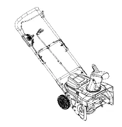
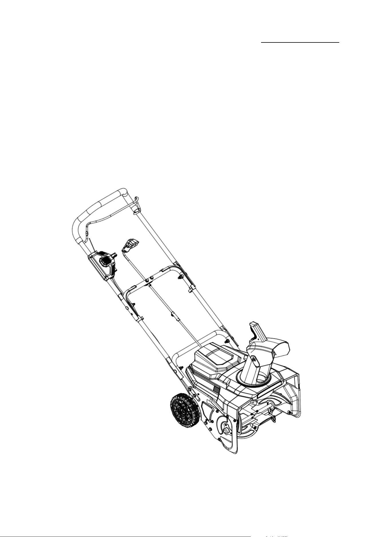
DC Snow Blower Repair Manual
Model:A082029

Service Manual
20250718_v1.0
目录 Directory
一、安全措施 Safety precautions
二、使用工具 Use of tools
三、维修与更换 Maintenance and replacement
1.更换皮带 Replace the belt
2.更换轮子 Replace the Wheel
3.维修/更换电子组件 Repair/Replace the Electronic Components
4.维修/更换电机 Repair/Replace the motor
5.更换齿轮 Replace the gear
6.更换 LED 灯 Replace the LED light
一、安全措施 Safety precautions
1.维修不应在户外的雨、雪、冰雹、灰尘中进行;
Maintenance should not be carried out in outdoor rain,
snow,hail,dust;
2.请断开电源开关,不允许在带电条件下进行维修:

Service Manual
20250718_v1.0
Please disconnect the power switch,
maintenance can not be carried out under live conditions:
3.请在维修工作中佩戴手套、护目镜、口罩和其他防护工具,以避免不必要的伤害:
Please wear gloves,eye masks,masks,and other
protective tools during the maintenance work to avoid
unnecessary damage:
4.维修环境应清洁、通风良好。避免零件和工具的误用和错位:
The maintenance environment is clean and clean,and
well ventilated.Avoid the misuse and dislocation of the
parts and tools:
5.请严格按照本维修手册进行相关维修工作;请使用正确的工具进行维修工作;
Please conduct relevant maintenance work in strict
accordance with this repair manual;please use the correct
tools for repair work;
6.请根据拆卸步骤记录零件的放置位置,以避免因装配错误而导致的重复组装。需要维修、
修理、更换的零件和零件必须区分开来,以避免装载错误:
Please record the placement position of the parts
according to the disassembly steps,so as to avoid repeatedassembly due to misas
sembly.What requires maintenance.repair,replacement parts and parts must be dis
tinguished to avoid misloading:
Service Manual
20250718_v1.0
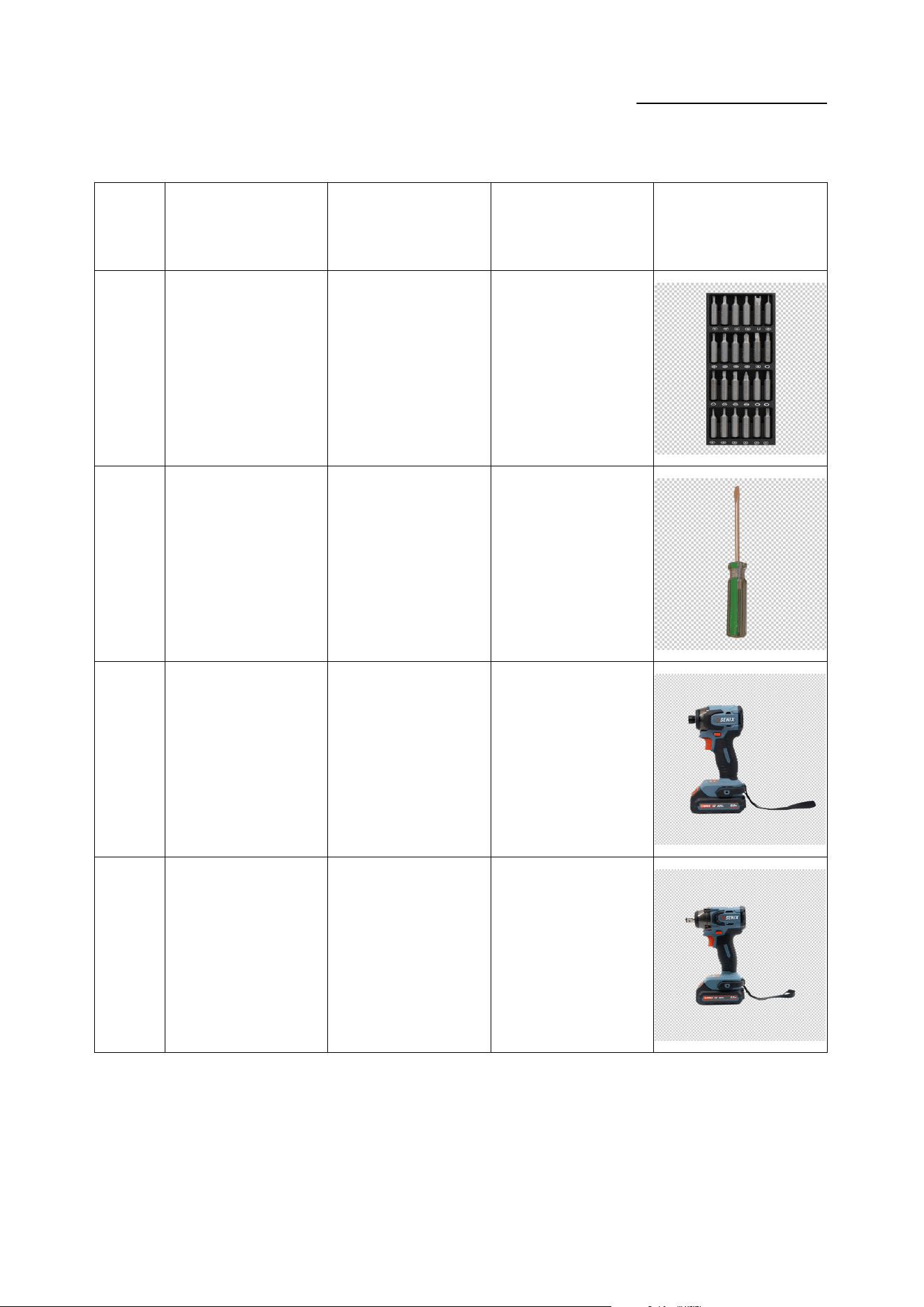
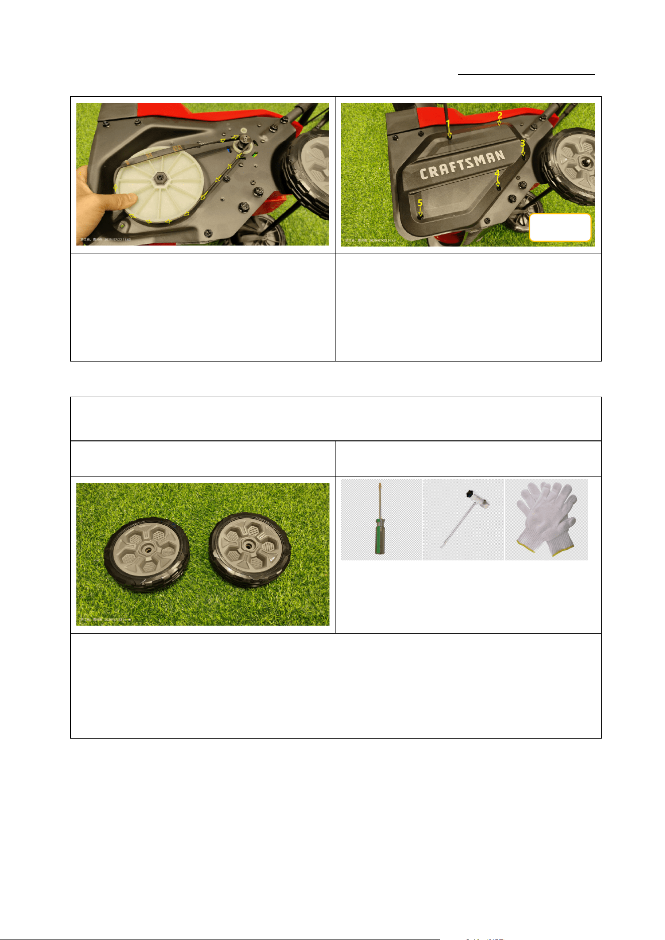
二、使用工具 Use of tools
序号 No. 品名 Name 规格 Specification 用途 Purpose 图片 Picture
1
螺丝刀头
SCREWDRIVER BITS
十字
拆装 ST 4.0/ST 5.0 十字螺
丝
2
一字起子
SLOTTED
SCREWDRIVER
Ø6 x150mm 拆卸皮带
4
电动螺丝批
Drill Driver
/ 拆装螺钉
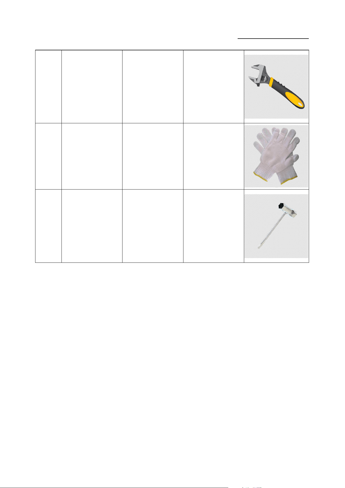
6
电动扳手
Impact Driver
/ 拆装轮轴螺母
Service Manual
20250718_v1.0
7
活动扳手
Active wrench
/ 拆装轮轴螺母
8
手套
GLOVE
/
防护
To protect hand s
9 套筒扳手 / 拆装轮轴螺母
Service Manual
20250718_v1.0
三、维修与更换 Repair and Replace
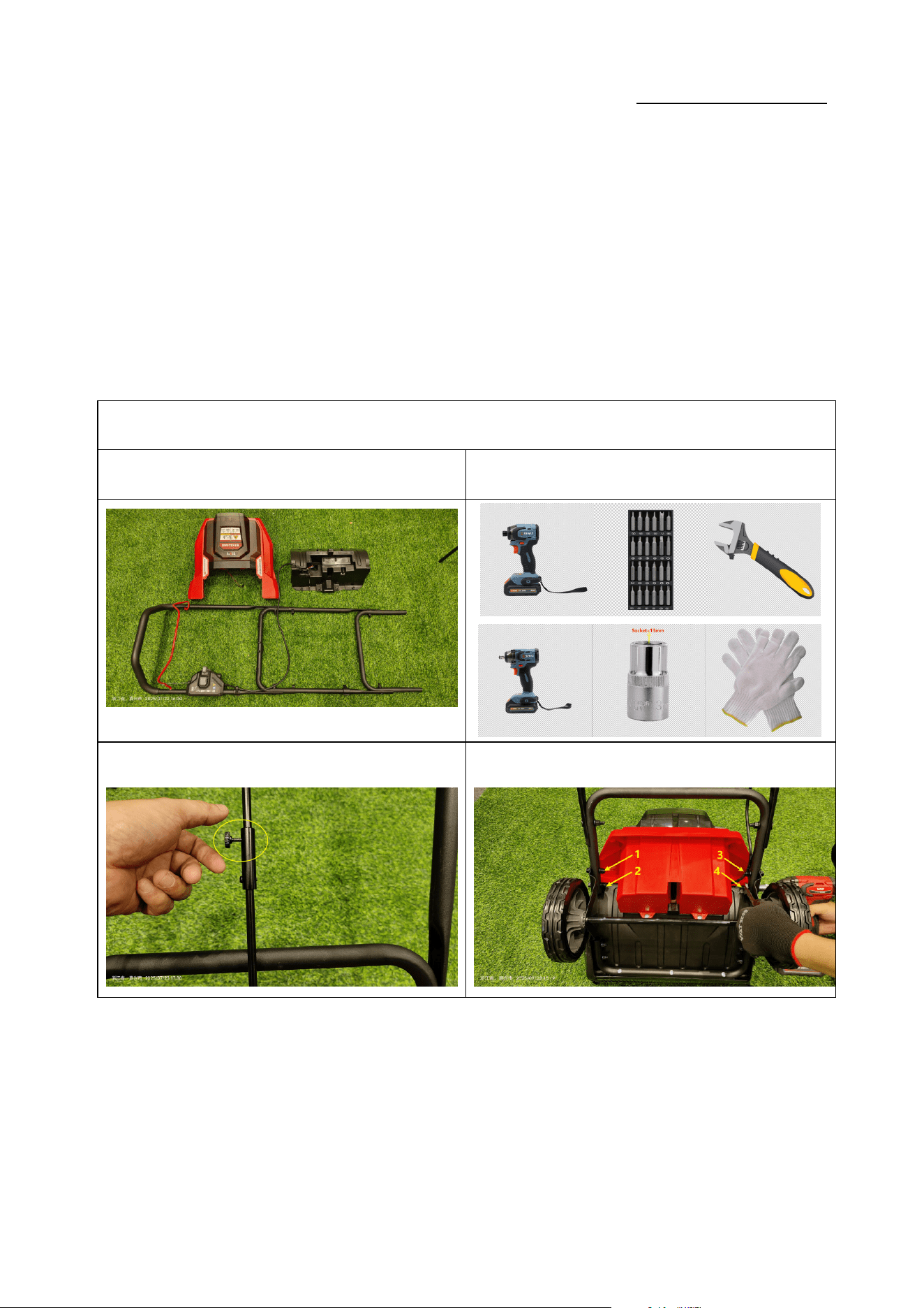
拆卸壳体 Replace the Housing
零件图片 Parts picture 使用工具 Use of tools
① ②
Service Manual
20250718_v1.0
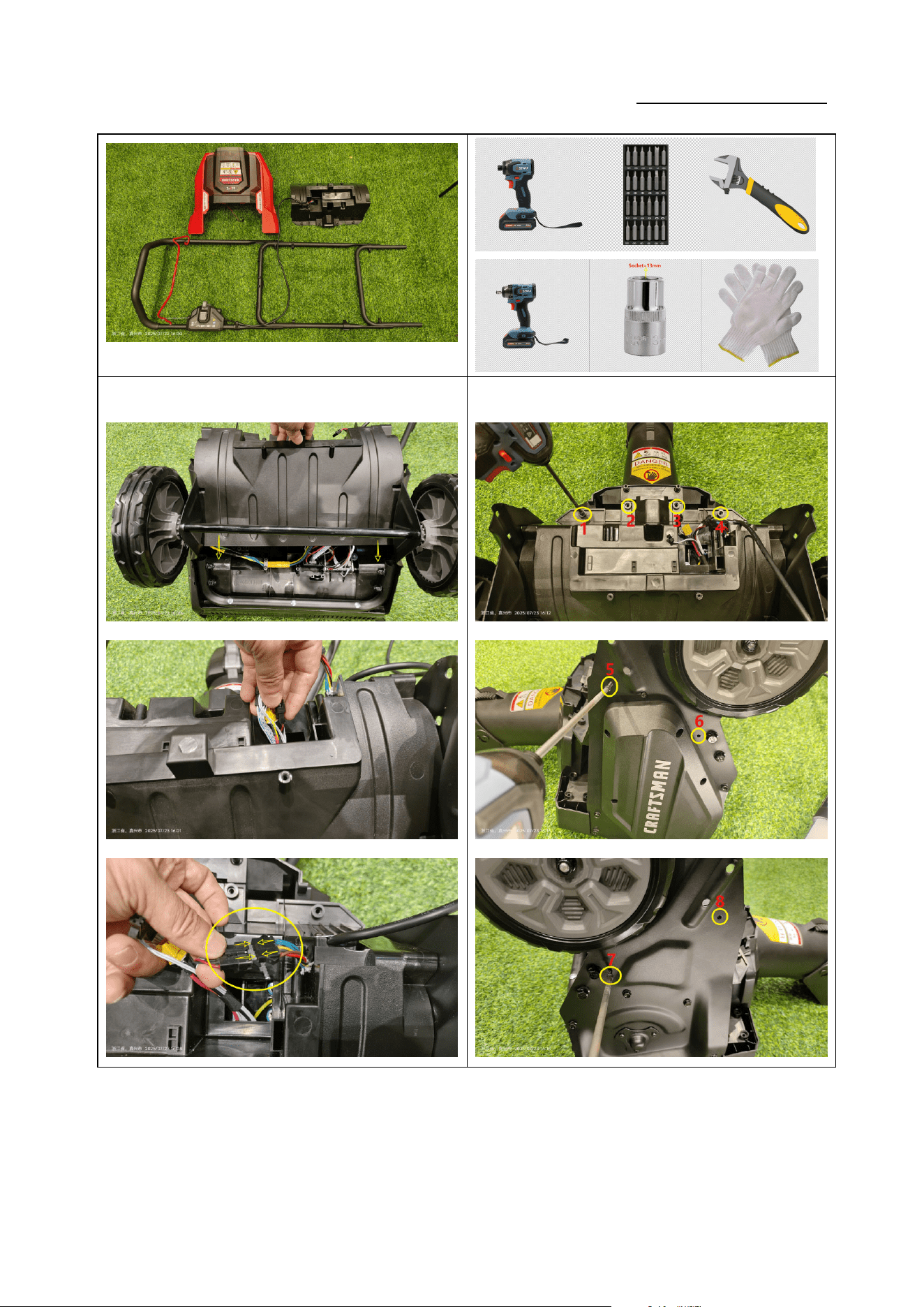
如图 1:拆下固定螺栓,取下金属轴;
Figure 1: Remove the fixing bolts and take off the
metal shaft.
如图 2:使用 13mm 扳手,拆下 4 颗固定螺栓,取下上把
手组件;(力矩:4-6N.m)
Figure 2: Use a 13 mm wrench to remove the 4 fixing
bolts and take off the upper handle assembly (torque:
4-6 N·m).
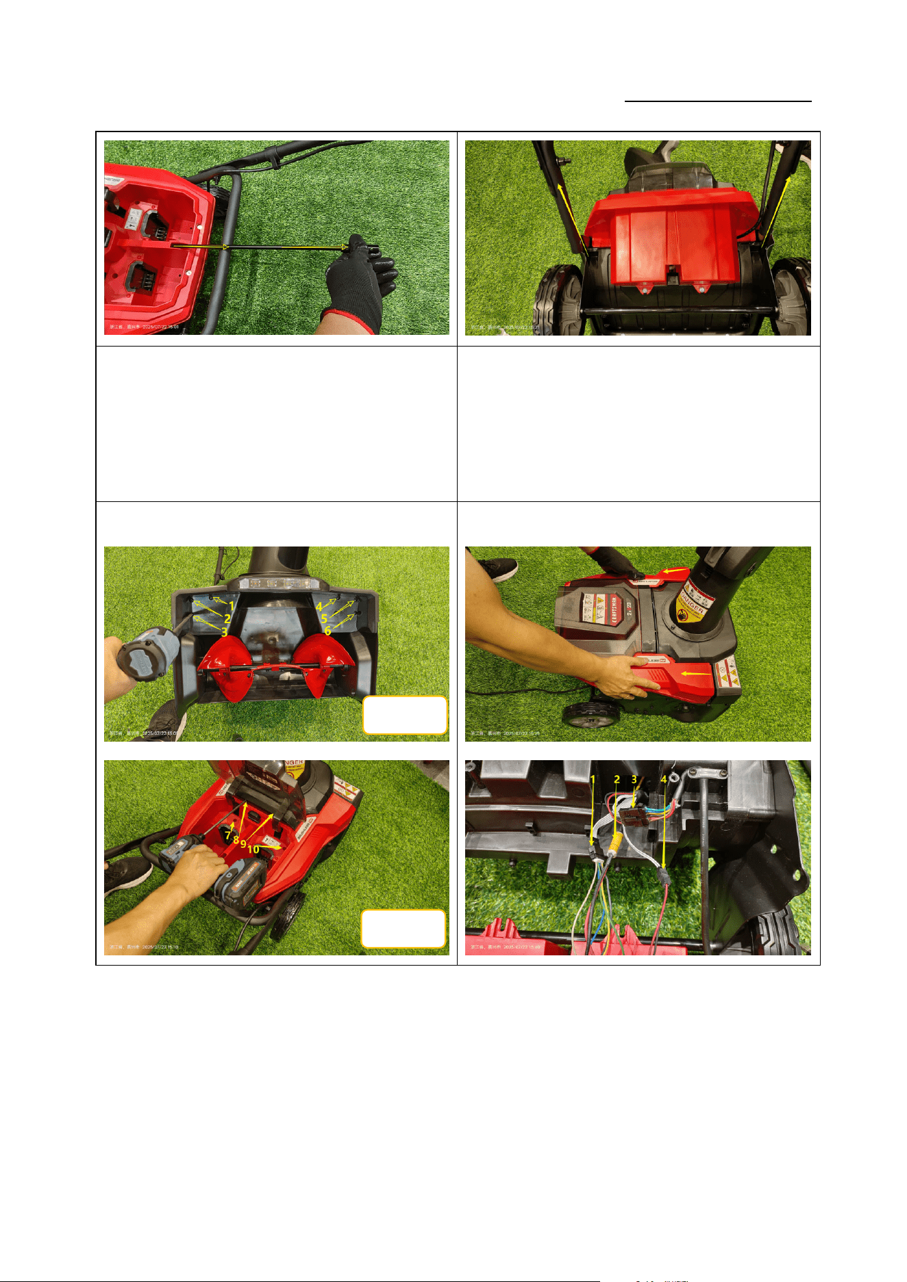
③
④
ST5*20
ST5*20
Service Manual
20250718_v1.0
如图 3:使用十字批头依次拆下 12 颗螺钉;(力矩:
1.4-1.6N.m)
Figure 3: Use a Phillips bit to sequentially remove the
12 screws (torque: 1.4-1.6 N·m).
如图 4:打开上盖,断开 4 个链接端子,取下上盖;
Figure 4: Open the upper cover, disconnect the 4
connectors, and remove the upper cover.
⑤
⑥
ST5*20
ST5*20
ST5*16
Service Manual
20250718_v1.0
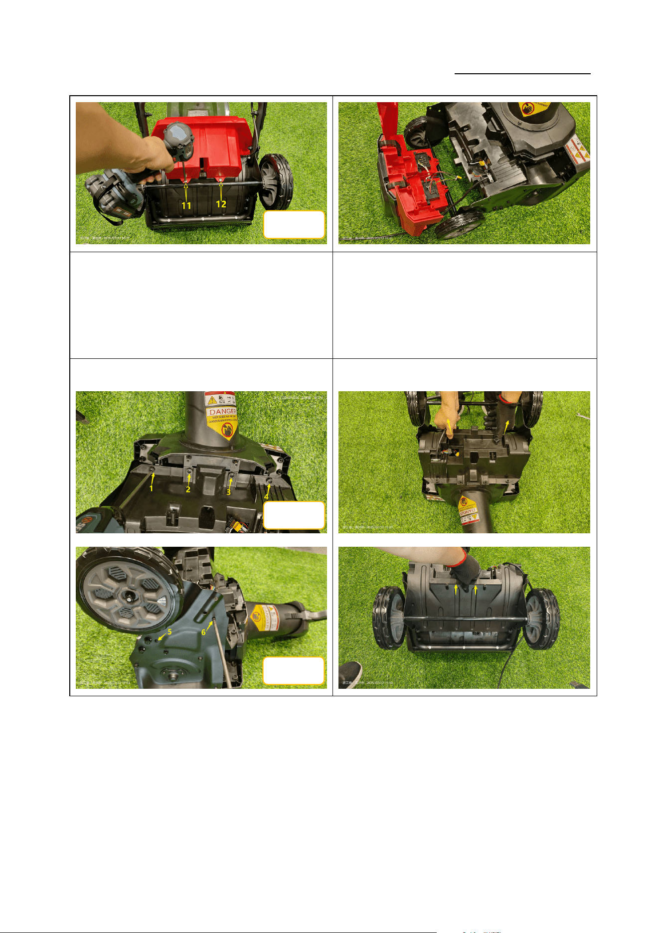
如图 5:使用十字批头依次拆下 8 颗 ST5*20
螺钉;(力矩:1.4-1.6N.m)
Figure 5: Use a Phillips bit to sequentially remove the 8
screws ST5×20 (torque: 1.4-1.6 N·m).
如图 6:取下后盖;
Figure 6: Remove the rear cover.
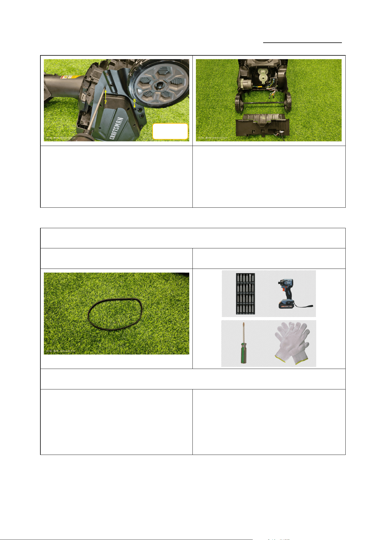
1.更换皮带 Replace the belt
零件图片 Parts picture 使用工具 Use of tools
1.1 拆卸皮带 Remove the belt
①②
ST5*20
Service Manual
20250718_v1.0
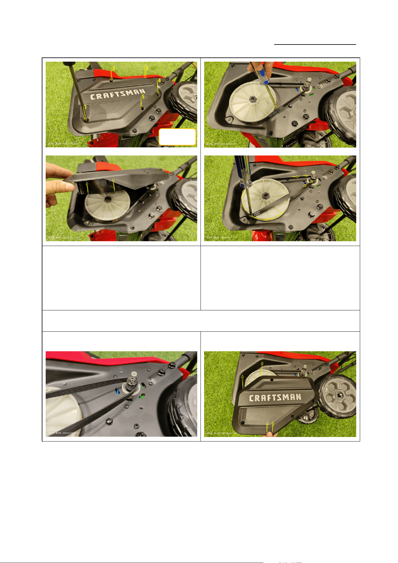
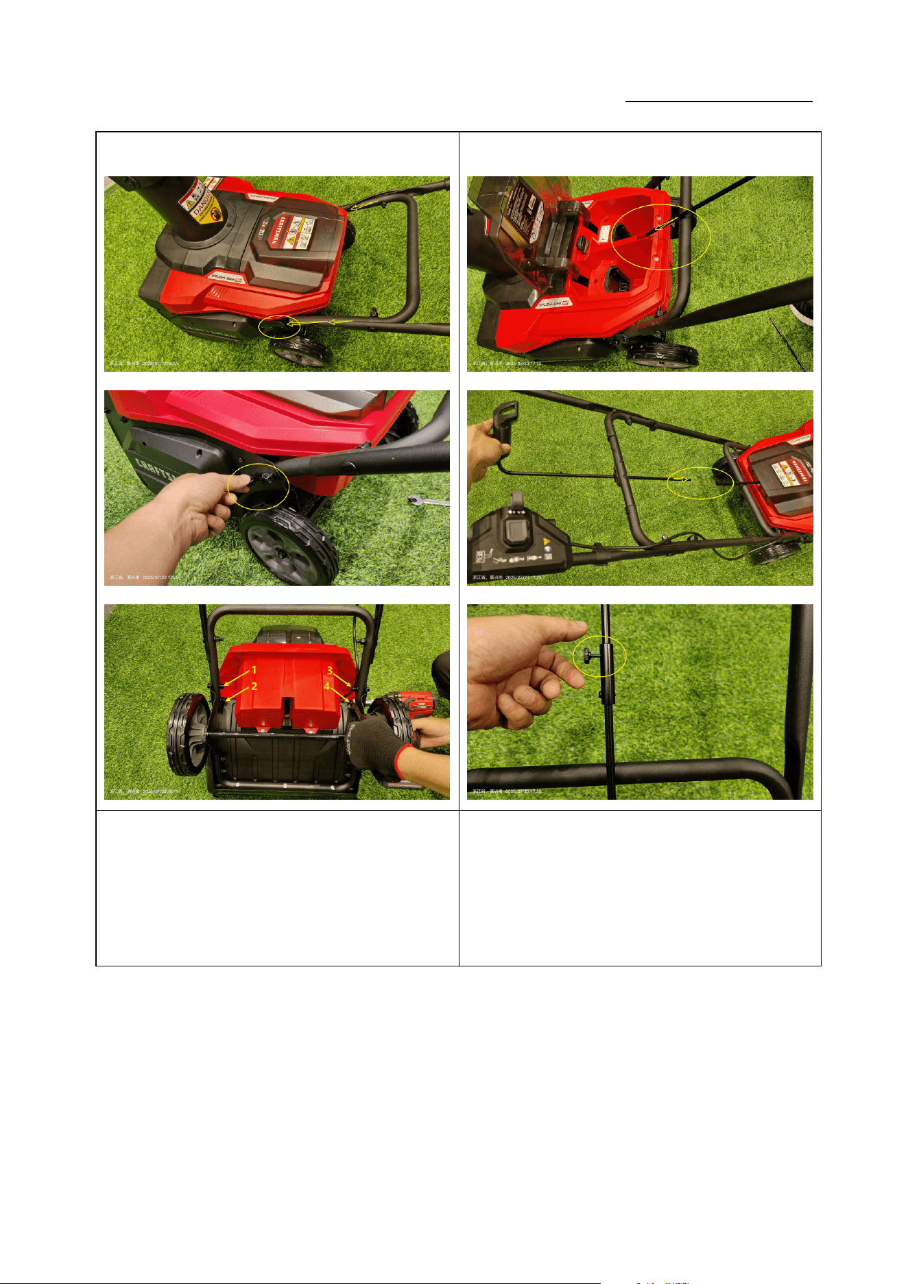
如图 1:使用十字批头拆下 5 颗 5*16 自攻螺钉,卸下侧盖;
(力矩:3-4N.m)
Figure 1: Use a Phillips bit to remove the 5
self-tapping screws ST5×16 and take off the side
cover (torque: 3-4 N·m).
如图 2:使用一字起子插入皮带内侧,顺时针旋转皮带轮,
取下皮带。
Figure 2: Insert a slotted screwdriver between the
belt and the pulley, turn the pulley clockwise and slip
the belt off.
1.2 安装皮带 Install the belt
① ②
ST5*16
Service Manual
20250718_v1.0
如图 1:将皮带安装到带轮槽内,顺时针旋转带轮,将皮
带完全安装到位。
Figure 1: Fit the belt into the pulley grooves, rotate the
pulley clockwise until the belt is fully seated.
如图 2:盖上侧盖,使用十字批头锁紧 5 颗 5*16 自攻螺钉;
(力矩:3-4N.m)
Figure 2: Replace the side cover and tighten the 5
self-tapping screws ST5×16 with a Phillips bit (torque:
3-4 N·m).
2.更换轮子 Replace the Wheel
零件图片 Parts picture 使用工具 Use of tools
2.1 拆卸轮子 Remove the Wheel
ST5*16
Service Manual
20250718_v1.0
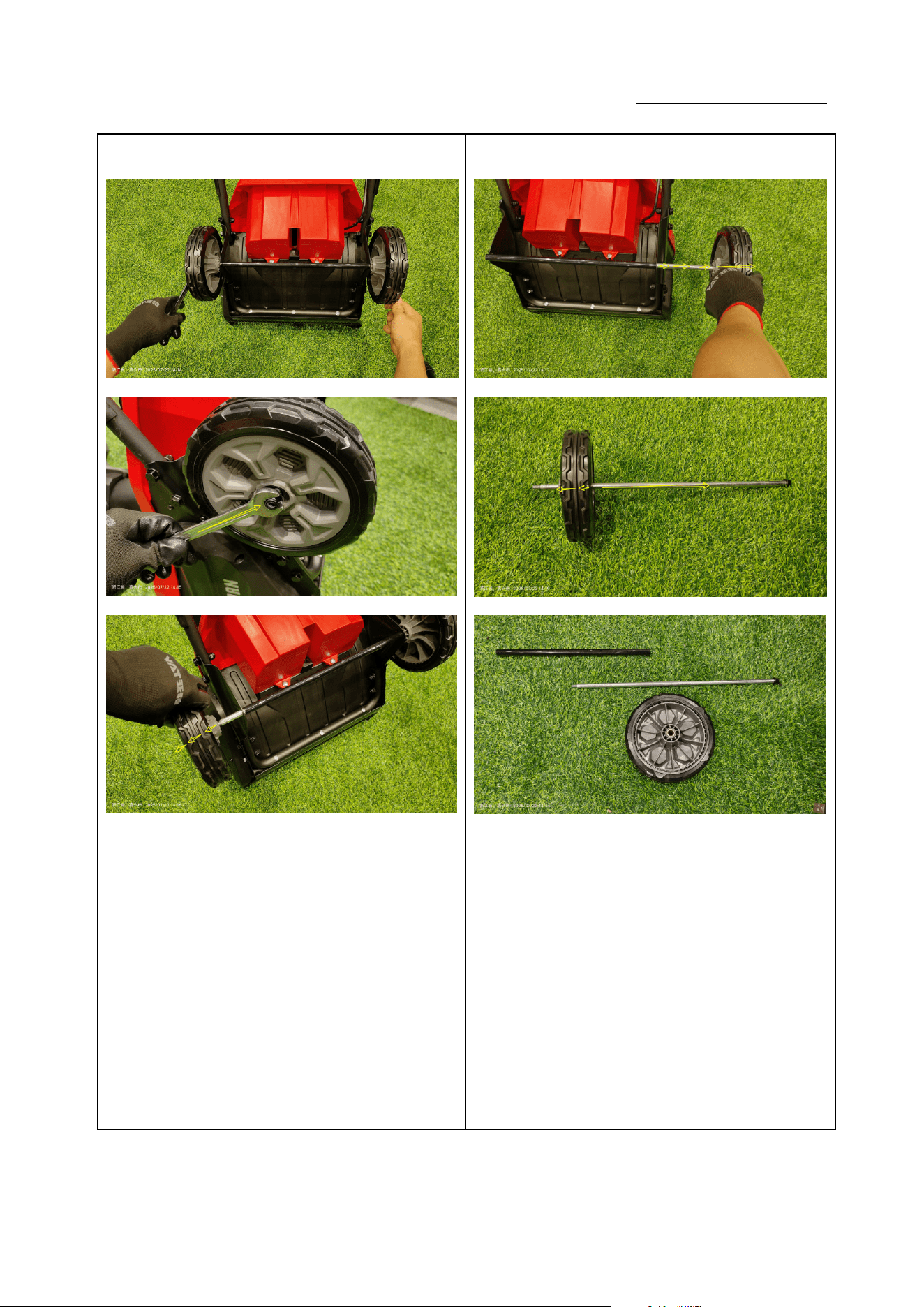
① ②
如图 1:使用两个 13mm 扳手拆下 M8 螺母,取下左轮;
(力矩:4-6N.m)
Figure 1: Use two 13 mm wrenches to loosen the M8
nut and remove the left wheel (torque: 4-6 N·m).
如图 2:拔出轮轴,取下右轮。
Figure 2: Pull out the wheel axle and remove the right
wheel.
Service Manual
20250718_v1.0
2.2 安装轮子 Install the Wheel
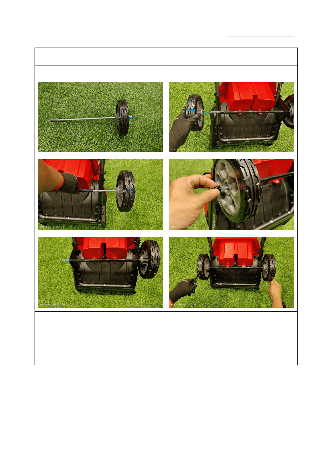
① ②
如图 1:将右轮安装到轮轴上,并穿过支架。
Figure 1: Fit the right wheel onto the axle and pass it
through the bracket.
如图 2:将左轮安装到轮轴上,使用 M13 扳手锁紧 M8 螺
母(力矩:4-6N.m)。;
Figure 2: Mount the left wheel onto the axle and
tighten the M8 nut with a 13 mm wrench (torque: 4-6
N·m).
Service Manual
20250718_v1.0
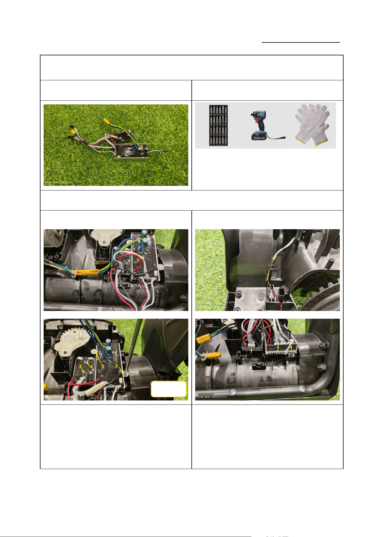
3.更换电子组件 Repair/Replace the Electronic Components
零件图片 Parts picture 使用工具 Use of tools
3.1 拆卸电子组件 Remove the Electronic Components
① ②
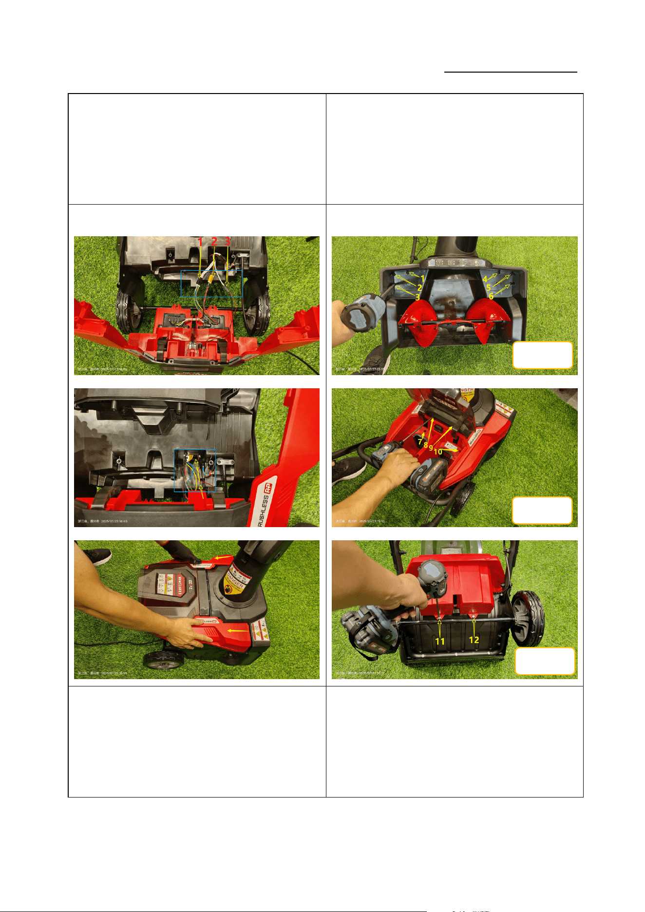
如图 1:断开电机连接线;使用十字批头拆下 4 颗 ST4*16
螺丝;(力矩:1.0-1.2N.m)
Figure 1: Disconnect the motor wiring; use a Phillips
bit to remove the 4 screws ST4*16 (torque: 1.0-1.2
N·m).
如图 2:拔下连接端子,取下电子组件;
Figure 2: Unplug the connectors and take out the
electronic assembly.
ST4*16
Service Manual
20250718_v1.0
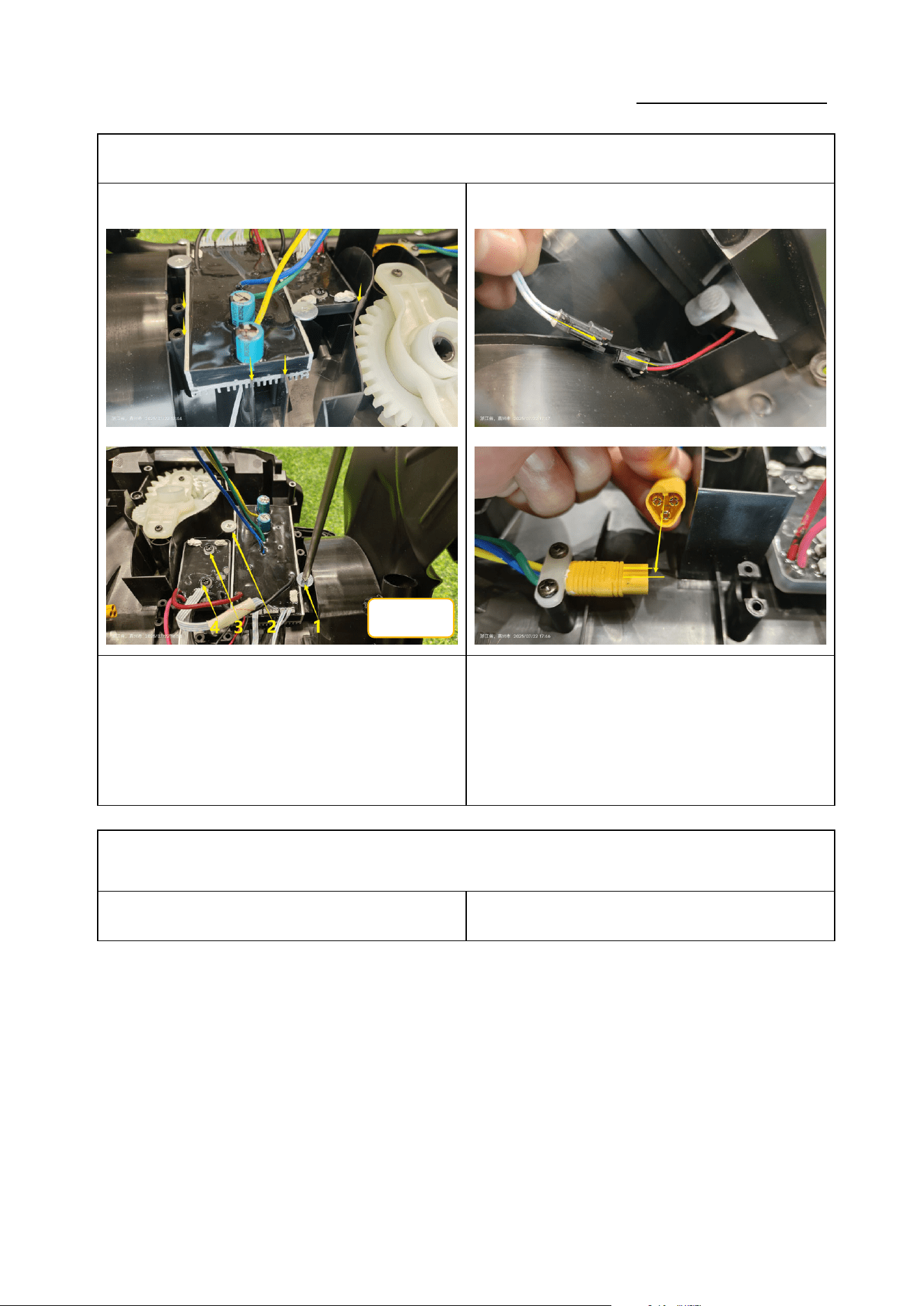
3.2 安装电子组件 Install the Electronic Components
① ②
如图 1:将电子组件安装到位,使用十字批头锁紧 4 颗
ST4*16 螺钉。(力矩:1.0-1.2N.m)。
Figure 1: Position the electronic assembly and
tighten the 4 screws ST4*16 with a Phillips bit
(torque: 1.0-1.2 N·m).
如图 2:插回两个连接端子;
Figure 2: Re-connect the two connectors.
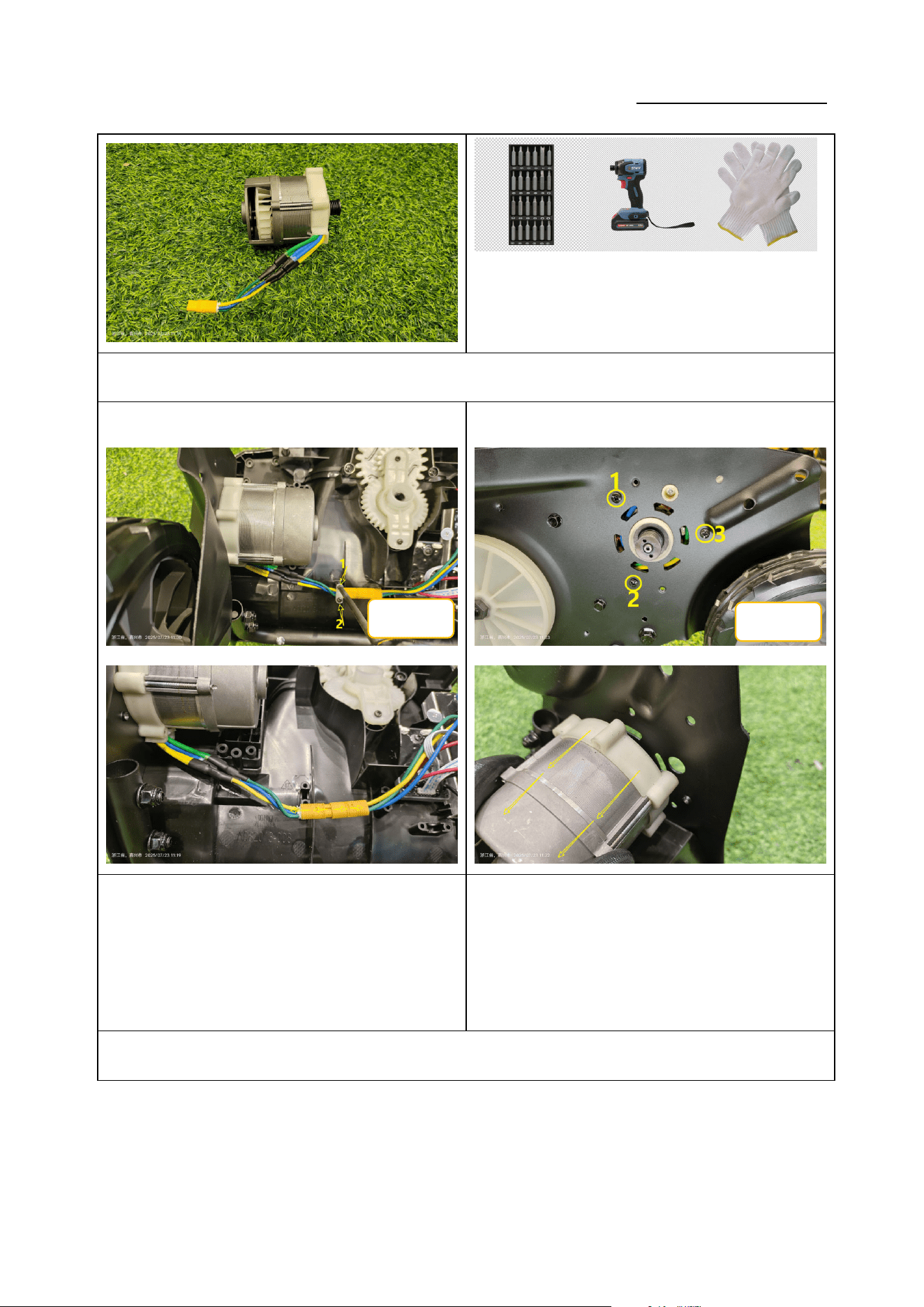
4.维修/更换电子组件 Repair/Replace the motor
零件图片 Parts picture 使用工具 Use of tools
ST4*16
Service Manual
20250718_v1.0
2.1 拆卸电机 Remove the motor
① ②
如图 1:使用十字批头拆下 2 颗 ST4*16 自攻螺钉,断开
连接线;(力矩:1.0-1.2N.m)
Figure 1: Use a Phillips bit to remove the 2
self-tapping screws ST4*16 and disconnect the
wiring (torque: 1.0-1.2 N·m).
如图 2:使用十字批头拆下 3 颗 ST5*20 自攻螺钉,取下
电机;(力矩:2.0-3.0N.m)
Figure 2: Use a Phillips bit to remove the 3
self-tapping screws ST5*20 and lift out the motor
(torque: 2.0-3.0 N·m).
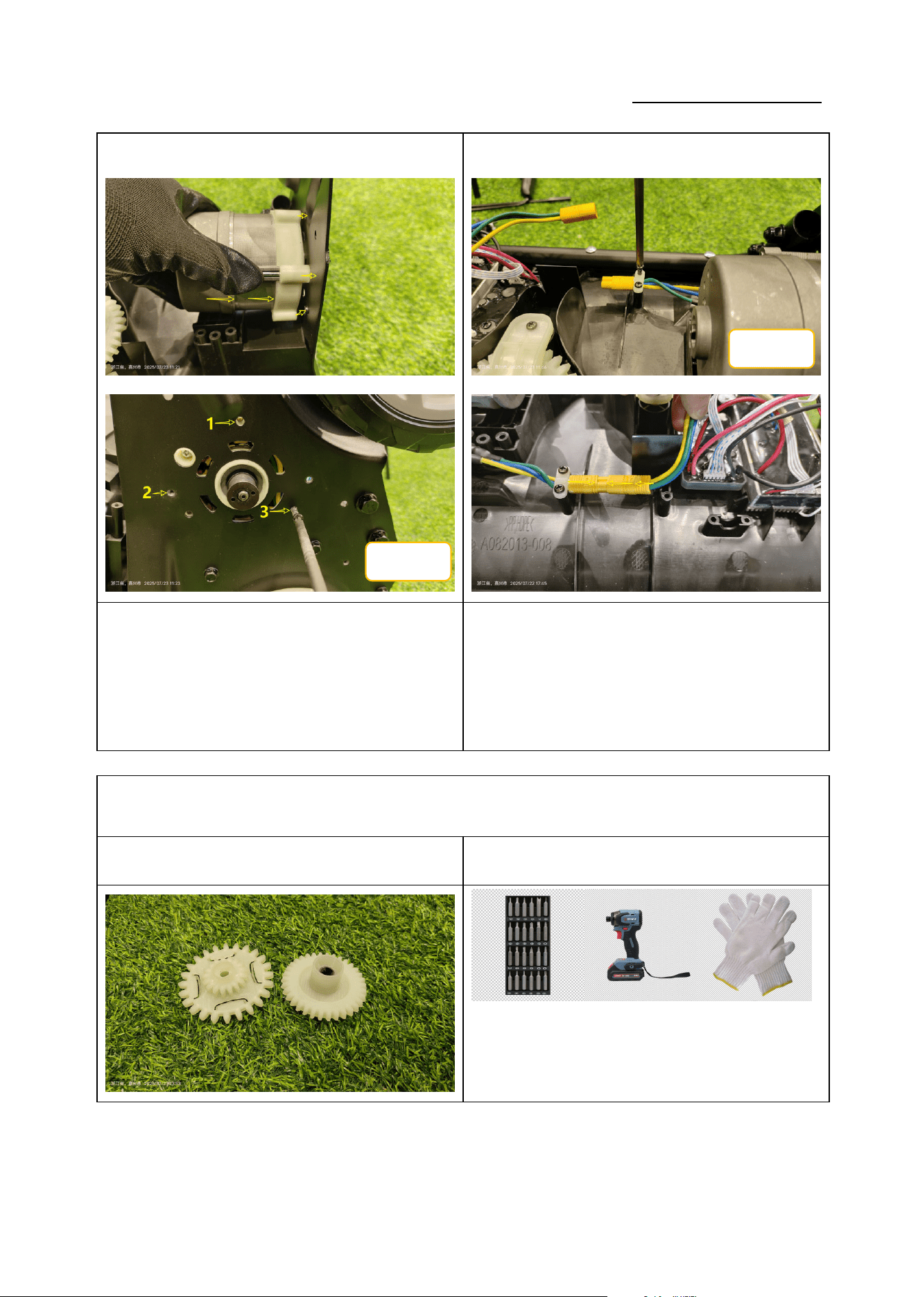
2.2 安装电机 Install the motor
ST4*16
ST5*20
Service Manual
20250718_v1.0
① ②
如图 1:将电机安装在支架上,使用十字批头锁紧 3 颗
ST5*20 螺钉。(力矩:2.0-3.0N.m)
Figure 1: Mount the motor on the bracket and
tighten the 3 screws ST5*20 with a Phillips bit
(torque: 2.0-3.0 N·m).
如图 2:使用十字批头锁紧 2 颗 ST4*16 自攻螺钉,插回
连接线;(力矩:1.0-1.2N.m)
Figure 2: Tighten the 2 self-tapping screws ST4*16
and reconnect the wiring (torque: 1.0-1.2 N·m).
5.更换齿轮 Replace the gear
零件图片 Parts picture 使用工具 Use of tools
ST5*20
ST4*16
Service Manual
20250718_v1.0
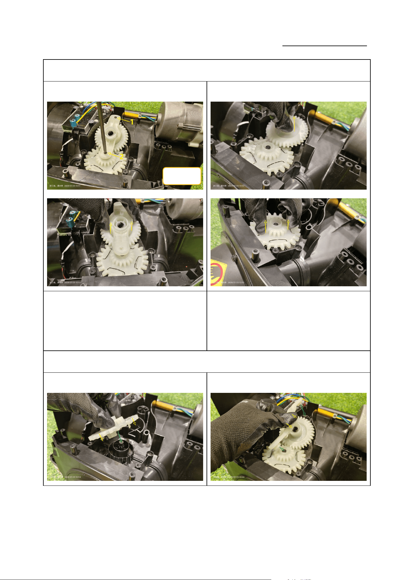
2.1 拆卸齿轮 Remove the gear
① ②
如图 1:使用十字批头拆下 2 颗 ST4*16 自攻螺钉,取下
塑料压板;(力矩:1.0-1.2N.m)
Figure 1: Use a Phillips bit to remove the 2
self-tapping screws ST4*16 and take off the plastic
pressure plate (torque: 1.0-1.2 N·m).
如图 2:依次取下两个塑料齿轮;
Figure 2: Remove the two plastic gears one by one.
2.2 安装齿轮 Install the gear
①
②
ST4*16
Service Manual
20250718_v1.0
如图 1:依次装回两个塑料齿轮。
Figure 1: Re-install the two plastic gears in sequence.
如图 2:装回塑料压板,使用十字批头锁紧 2 颗 ST4*16
螺钉;(力矩 1.0-1.2N.m)
Figure 2: Re-install the plastic pressure plate and
tighten the 2 screws ST4*16 with a Phillips bit
(torque: 1.0-1.2 N·m).
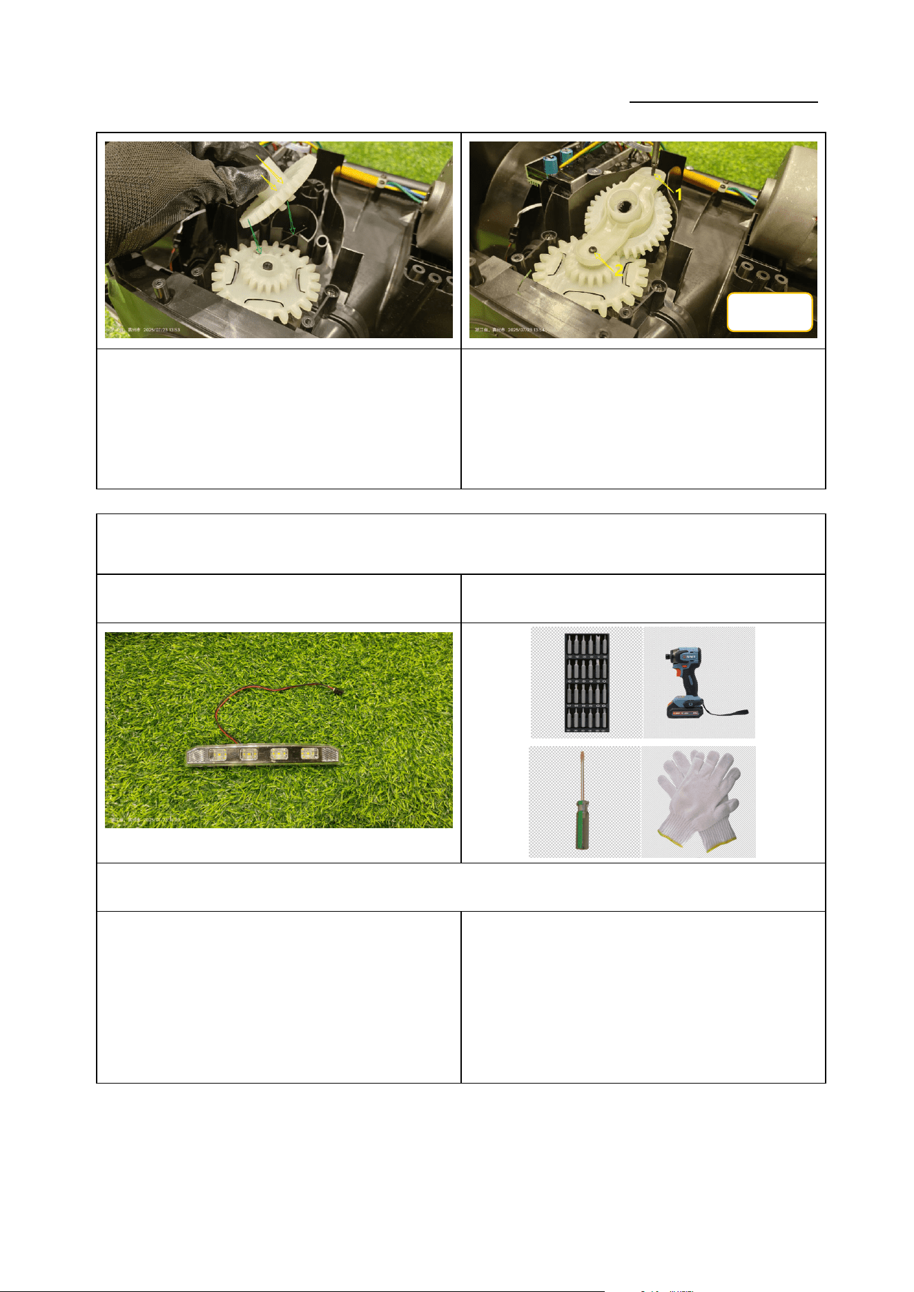
6.更换 LED 灯 Replace the LED light
零件图片 Parts picture 使用工具 Use of tools
2.1 拆卸 LED 灯 Remove the LED light
①②
ST4*16
Service Manual
20250718_v1.0
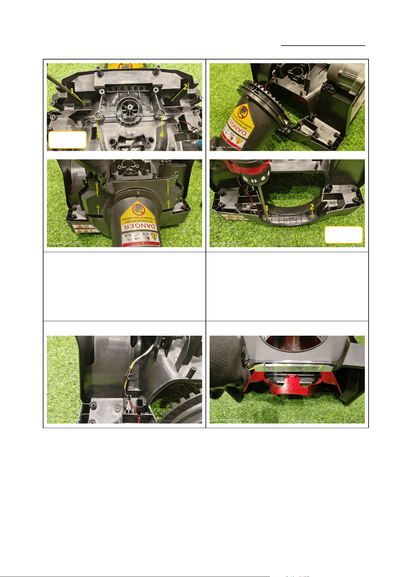
如图 1:使用十字批头拆下 2 颗 ST5*20 自攻螺钉,取下
支架;(力矩:1.2-1.4N.m)
Figure 1: Use a Phillips bit to remove the 2
self-tapping screws ST5*20 and take off the bracket
(torque: 1.2-1.4 N·m).
如图 2:取下喷口,使用十字批头拆下 2 颗 ST4*16 自攻
螺钉,(力矩:1.0-1.2N.m)
Figure 2: Remove the nozzle, then use a Phillips bit to
remove the 2 self-tapping screws ST4*16 (torque:
1.0-1.2 N·m).
③
④
ST5*20
ST4*16
Service Manual
20250718_v1.0
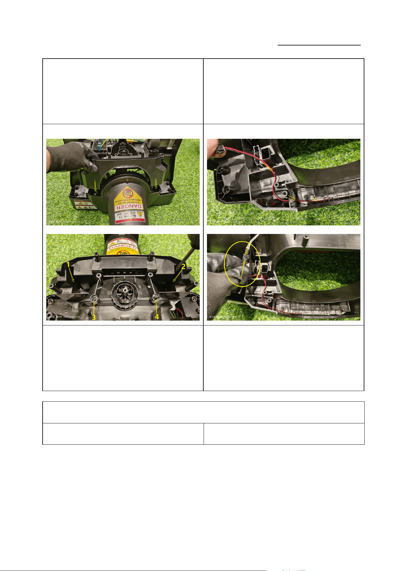
如图 3:断开端子,将连接线从线槽中取出;
Figure 3: Disconnect the connector and pull the wire
out of the cable channel.
如图 4:使用一字起子将 LED 灯挑起,取出 LED 灯;
Figure 4: Use a flat-blade screwdriver to pry out and
remove the LED light.
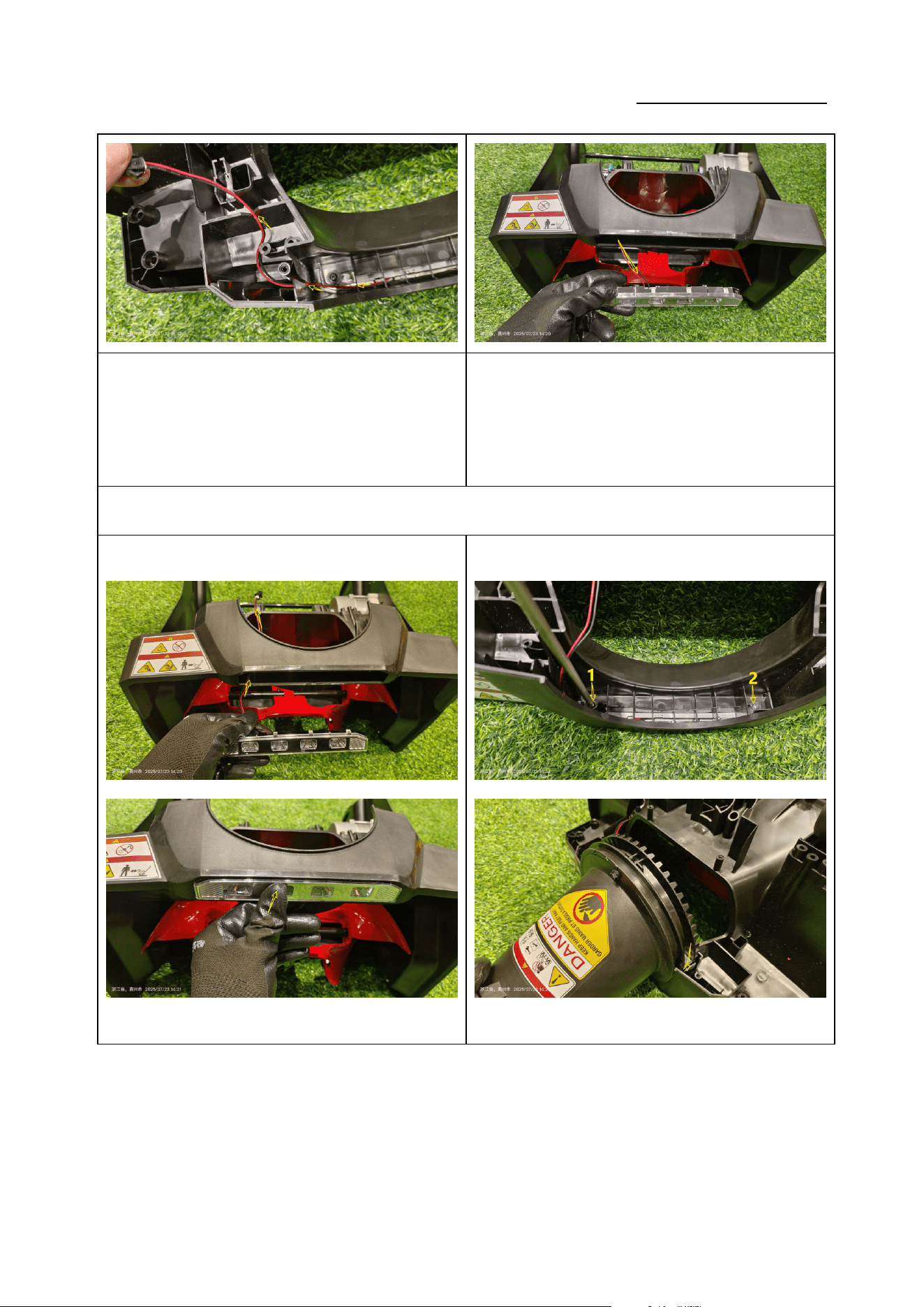
2.2 安装 LED 灯 Install the LED light
① ②
Service Manual
20250718_v1.0
如图 1:将 LED 灯装回机壳;
Figure 1: Fit the LED light back into the housing.
如图 2:使用十字批头锁紧 2 颗 ST4*16 自攻螺钉,装回
喷口;(力矩:1.0-1.2N.m)
Figure 2: Tighten the 2 screws ST4*16 with a Phillips
bit and reinstall the nozzle (torque: 1.0-1.2 N·m).
③ ④
如图 3:装回支架,使用十字批头锁紧 2 颗 ST5*20 自攻
螺钉;(力矩:1.2-1.4N.m)
Figure 3: Re-install the bracket and tighten the 2
screws ST5*20 with a Phillips bit (torque: 1.2-1.4
N·m).
如图 4:将连接线卡入线槽,插回连接线端子;
Figure 4: Snap the wire into the cable channel and
reconnect the connector.
安装壳体 Install the Housing
零件图片 Parts picture 使用工具 Use of tools
Service Manual
20250718_v1.0
① ②
Service Manual
20250718_v1.0
如图 1:装回后罩,拉出连接线头,插回电源线端子;
Figure 1: Re-install the rear cover, pull out the wire
ends and reconnect the power connector.
如图 2:使用十字批头依次锁紧 8 颗螺钉;(力矩:1.4-1.6
N·m)
Figure 2: Use a Phillips bit to sequentially tighten the
8 screws (torque: 1.4-1.6 N·m).
③ ④
如图 3:插回 3 个连接线端子并放回孔内,装回上盖;
Figure 3: Re-connect the 3 wire connectors and place
them back into their holes, then reinstall the upper
cover.
如图 4:使用十字批头依次锁紧 12 颗螺钉;(力矩:
1.4-1.6N.m)
Figure 4: Use a Phillips bit to sequentially tighten the
12 screws (torque: 1.4-1.6 N·m).
ST5*20
ST5*20
ST5*16
Service Manual
20250718_v1.0
⑤ ⑥
如图 5:装回上把手组件,使用 13mm 扳手锁紧 4 颗固定
螺栓;(力矩:4-6N.m)
Figure 5: Re-install the upper handle assembly and
tighten the 4 fixing bolts with a 13 mm wrench
(torque: 4-6 N·m).
如图 6:装回金属摇杆,拧回紧固定螺栓;
Figure 6: Re-install the metal rocker and tighten the
fixing bolt.