Loading ...
Loading ...
Loading ...
Emergencies
Note
●
The v
ehicles must not touch each other,
otherwise electricity could flow as soon as
the positive terminals are connected.
●
The discharged battery must be properly
connected to the on-board network.
Positive pole at the jump start
points
Fig. 53
In the engine compartment: jump start
positiv
e pole
+
.
On some vehicles, there is a starting assis-
t
ance terminal in the engine compartment,
under a labelled cover.
Jump start: description
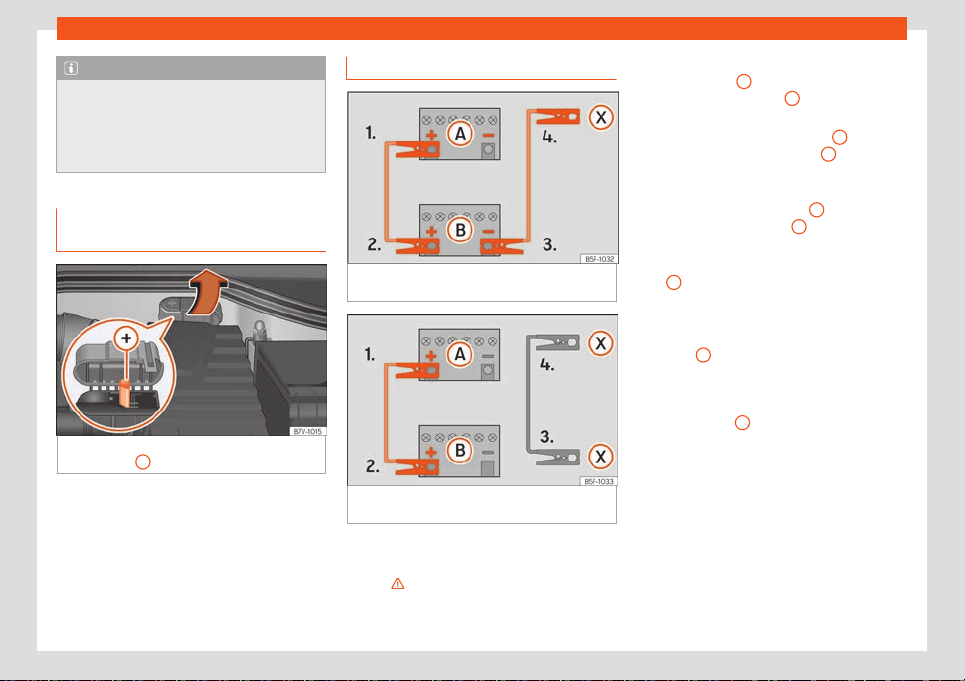
Fig. 54
Diagram of connections for vehicles
without St
art Stop system
Fig. 55
Diagram of connections for vehicles
with St
art Stop system
Jump lead terminal connections
S
witch off the ignition of both vehicles
›››
.
1.
Connect one end of the r
ed jump lead to
the positive
+
terminal of the vehicle
with the fl
at battery
A
›
››
Fig. 54.
Connect the other end of the red jump
lead to the positive terminal
+
in the ve-
hicl
e providing assistance
B
.
In v
ehicles without a Start-Stop system:
connect one end of the black jump lead
to the negative terminal
–
of the vehicle
pr
oviding the current
B
›
››
Fig. 54.
In vehicles with a Start-stop system:
connect one end of the black jump lead
X
to a suitable ground terminal, to a sol-
id piece of met
al in the engine block, or
to the engine block itself
›››
Fig. 55.
Connect the other end of the black jump
lead
X
to a solid metal component bol-
t
ed to the engine block or to the engine
block itself of the vehicle with the flat
battery. Do not connect it to a point near
the battery
A
.
P
osition the leads in such a way that
they cannot come into contact with any
moving parts in the engine compart-
ment.
Starting
Start the engine of the vehicle with the
boosting battery and let it run at idling
speed.
2.
3.
4a.
4b.
5.
6.
7.
52
Loading ...
Loading ...
Loading ...