Loading ...
Loading ...
Loading ...
Parts on the system board
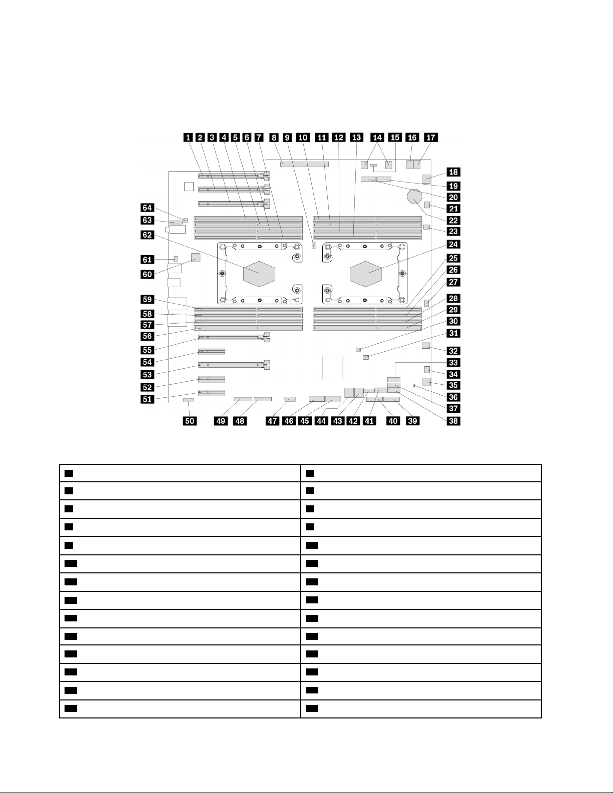
The following illustration shows the locations of the parts on the system board.
Note: The system board might look slightly different from the illustration.
Figure 4. Parts on the system board
1 PCIe 3.0 x16 card slot 6 2 PCIe 3.0 x16 card slot 7
3 PCIe 3.0 x16 card slot 8
4 Microprocessor 2 memory slot 2
5 Microprocessor 2 memory slot 6 6 Microprocessor 2 memory slot 4
7 Microprocessor 2 memory slot 8 8 Power supply connector
9 Microprocessor fan connector 2
10 Microprocessor 1 memory slot 1
11 Microprocessor 1 memory slot 5 12 Microprocessor 1 memory slot 3
13 Microprocessor 1 memory slot 7
14 Optical-drive fan connectors
15 VROC connector
16 4-pin power connector
17 4-pin power connector
18 Front-fan-assembly connector
19 M.2 solid-state drive slot 2 20 M.2 solid-state drive slot 1
21 Blind-connect assembly (BCA) 2 connector 22 Coin-cell battery
23 Thermal-sensor connector 24 Microprocessor socket 1
25 Microprocessor 1 memory slot 8 26 Microprocessor 1 memory slot 4
27 Microprocessor fan connector 1
28 Microprocessor 1 memory slot 6
8 P920 User Guide
Loading ...
Loading ...
Loading ...