Loading ...
Loading ...
Loading ...
XNX Universal Transmitter
Section 2 - Installation and Operation
44
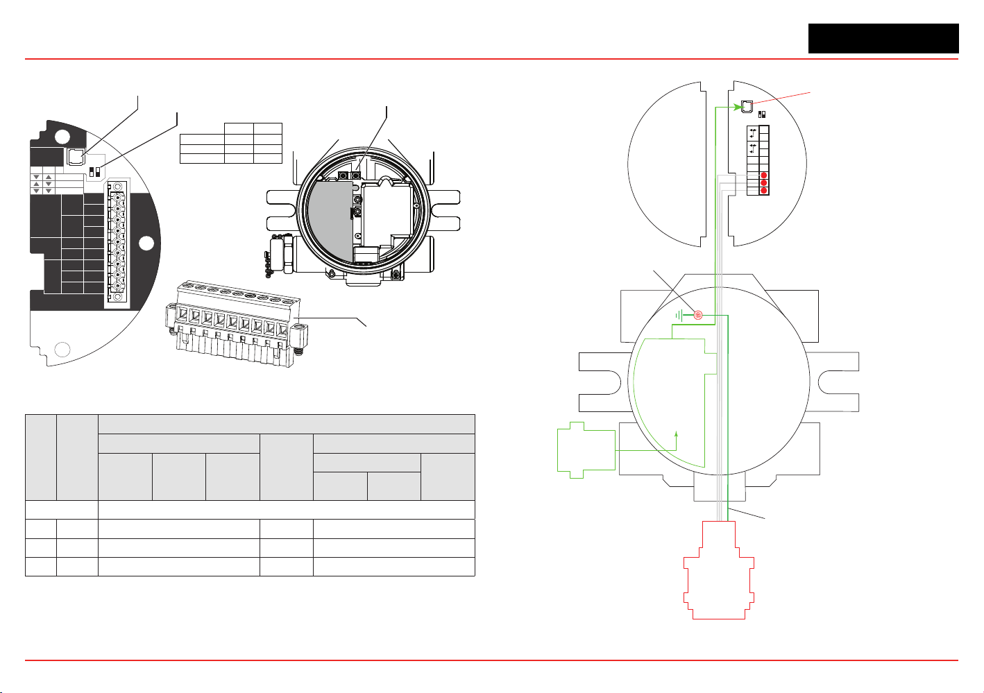
HART
20 mA
Operation
LOCAL
J1
S1
+V 1-1
mV TB-1
MPD, 705
Sensepoint
4-20mA
HART
16-32 VDC
6.5W max.
1-2
-V 1-3
1-4
+mA 1-5
-mA 1-6
Sense
1-7
0v 1-8
Ref 1-9
S1
Source
Sink
Isolated
S2
S2
J1 - Local HART Option Connector
1
2
3
4
5
6
7
8
9
internal
grounding lugs
S1 and S2 - 20mA Output
Jumper Switch
S2
S1
▼
▼
Isolated
▲
Sink
▼
Source
▼
▲
XNX mV TB-1
Figure 45. mV personality board terminal blocks and jumper switches.
TB-1 Desc.
Wire Color from Sensor
mV Catalytic Bead Sensor
Sensept
PPM*
mv MPD w/IR Sensor
MPD
705
705HT
Sensept
Senspt HT
IR 5%
IR Flam
CO
2
CH
4
Pins 1-6 See subsections in Section 2.2.4 for pin identification
7 Sense Brown Red Brown
8 0v White Green White
9 Ref Blue Blue Blue
*Internal earth ground; approximately one inch of the black sheath that contains the Sensepoint PPM’s four wires (red, blue,
green, silver) must be split to allow the silver grounding wire to reach the internal grounding lugs.
Local HART
IS Barrier
(optional)
HART
Adaptor
4
3
2
1
Ref
+
9
8
7
6
5
J1 HART
S1 S2
Terminal Block 1
Com
Sense
-
Optional Local HART
IS Barrier must
be connected to J1
Ground Wire from
Sensepoint PPM and HT
Internal Ground Lug
MPD
705
Sensepoint
Figure 46. mV Personality Wiring
Loading ...
Loading ...
Loading ...