

XNX Universal Transmitter
Table of Contents
1
Table of Contents
Safety
Warnings
�������������������������������������������������������������������������������5
Cautions
��������������������������������������������������������������������������������7
Notes
������������������������������������������������������������������������������������7
Information
����������������������������������������������������������������������������8
1 Introduction
1�1 Product Description �����������������������������������������������������������10
1�1�1 The XNX
®
Universal Transmitter ��������������������������������10
1�1�2 20 mA/HART
®
Output ������������������������������������������������11
1�1�3 Communications ��������������������������������������������������������11
1�1�4 Certifications ��������������������������������������������������������������11
1�1�5 Patents �����������������������������������������������������������������������12
1�2 Product Overview ���������������������������������������������������������������12
1�2�1 Enclosure �������������������������������������������������������������������12
1�2�2 Cover �������������������������������������������������������������������������13
1�2�3 POD ��������������������������������������������������������������������������14
1�3 Options �������������������������������������������������������������������������������14
1�3�1 Local HART ��������������������������������������������������������������14
1�3�2 Relays ������������������������������������������������������������������������14
1�3�3 Modbus ���������������������������������������������������������������������15
1�3�4 Foundation Fieldbus ��������������������������������������������������15
1�3�5 XNX Accessories �������������������������������������������������������15
1�4 The XNX Front Panel ����������������������������������������������������������17
1�4�1 Controls and Navigation ��������������������������������������������18
1�4�2 The General Status Screen ���������������������������������������19
1�5 Main Menu ��������������������������������������������������������������������������22
1�5�1 XNX Menu Map ���������������������������������������������������������23
2 Installation and Operation
2�1 Mounting and Location of Sensors �������������������������������������28
2�1�1 Mounting the XNX
®
Universal Transmitter ������������������28
2�2 Wiring the XNX Transmitter �������������������������������������������������30
2�2�1 General Wiring Considerations ����������������������������������30
2�2�2 Distance Considerations for Installation���������������������31
2�2�3 POD Connections ������������������������������������������������������36
2�2�4
4-20mA Output, Common Connections, and Power
Settings ��������������������������������������������������������������������������������37
2�2�5
Foundation Fieldbus Wiring ������������������������������������������38
2�2�6 Terminal Block Connections ���������������������������������������38
2�2�7 EC Personality Wiring ������������������������������������������������39
XNX Electrochemical Sensor Installation
����������������40
XNX EC Sensor Remote Mounting Kit
��������������������41
2�2�8 mV Personality Wiring ������������������������������������������������ 43
2�2�9 IR Personality Wiring �������������������������������������������������46
Connecting a Searchpoint Optima Plus or Searchline
Excel
�����������������������������������������������������������������������46
Connecting Generic mA Devices
����������������������������47
2�3 Options �������������������������������������������������������������������������������51
2�3�1 Local HART Interface �������������������������������������������������51
2�3�2 Relays ������������������������������������������������������������������������53
2�3�3 Modbus ���������������������������������������������������������������������53
2�3�4 Foundation Fieldbus ��������������������������������������������������54
2�4 Powering the XNX for the First Time �����������������������������������55
2�4�1 XNX Units Configured for EC, mV, and IR
(except Searchline Excel) ��������������������������������������������55
2�4�2 LCD and LED Test �����������������������������������������������������56
2�4�3 XNX IR Units Configured for Searchline Excel ����������56
TOC
XNX Universal Transmitter
Table of Contents
2
Table of Contents
2�5 Configuring the XNX Universal Transmitter ������������������������57
Select Language �������������������������������������������������57
Set Date & Time �������������������������������������������������58
Set mV Sensor Type �������������������������������������������59
Set mA Sensor Type �������������������������������������������60
Range & Alarms��������������������������������������������������67
Latching / Non-Latching ��������������������������������������69
Set Units ��������������������������������������������������������������70
mA Levels �����������������������������������������������������������70
Calibration Interval ����������������������������������������������71
✓
Accept New Sensor Type ������������������������������������72
Beam Block Options �����������������������������������������72
Path Length ��������������������������������������������������������74
Unit ID �����������������������������������������������������������������75
Relay Options �����������������������������������������������������76
Fieldbus Options �����������������������������������������������77
Configure Security �����������������������������������������������78
2�6 Verifying the XNX Configuration �����������������������������������������79
2�6�1 Test Menu ���������������������������������������������������������������79
X
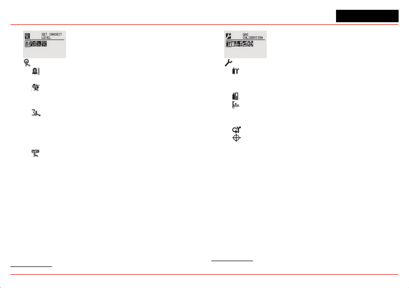
Inhibit ������������������������������������������������������������������79
Force mA Output ������������������������������������������������80
Force Relays ������������������������������������������������������81
Alarm/Fault Simulation ���������������������������������������81
2�6�2
?
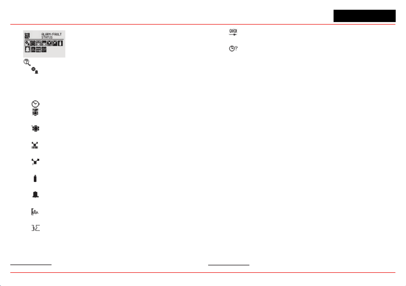
Information Menu ���������������������������������������������������83
Alarm/Fault Status ����������������������������������������������83
Date & Time ��������������������������������������������������������83
Transmitter Data ��������������������������������������������������83
?
Transmitter Status ����������������������������������������������84
Sensor Data ��������������������������������������������������������85
?
Sensor Status �����������������������������������������������������85
Gas Data ���������������������������������������������������������������85
Range/Alarm Settings �����������������������������������������85
mA Level Settings �����������������������������������������������86
Fieldbus Settings �����������������������������������������������86
Relay Data ����������������������������������������������������������86
?
Event History ����������������������������������������������������� 87
3 Calibration
3�1 Gas Calibration Menu ����������������������������������������������������90
3�2 Calibration ��������������������������������������������������������������������������90
3�2�1 Zero and Span Calibration for XNX EC Sensors, mV
Sensors, and Searchpoint Optima ��������������������������������������91
3�2�2 Calibration Procedure ������������������������������������������������91
3�2�3 Using the Calibration Cup ������������������������������������������93
3�2�4
Zero and Span Calibration of XNX EC Hydrogen
Sulfide (H
2
S) Sensors ���������������������������������������������������94
3�2�5 705/705HT Calibrating �����������������������������������������������94
3�2�6 Sensepoint/Sensepoint HT Calibrating ����������������������94
3�2�7 Calibrating the Searchpoint Optima Plus �������������������94
3�2�8
Zero and Span Calibration for MPD Sensors ���������������������� 97
3�2�9 MPD Flammable Sensor Operational Life �����������������98
3�2�10 XNX EC Sensor Operational Life �����������������������������98
3�3 Functional Gas Testing (Bump Testing) ������������������������������99
3�4 Calibrate mA Output ���������������������������������������������������100
3�5 Align Excel (Searchline Excel) �������������������������������������100
3�6 Soft Reset ��������������������������������������������������������������������101

XNX Universal Transmitter
Table of Contents
3
Table of Contents
4 Maintenance
4�1 MPD Sensor Cartridge Replacement �������������������������������104
4�2 XNX
®
EC Sensor Cartridge Replacement ������������������������105
4�2�1 Replacing with the Same Cartridge Type �����������������105
4�2�2 Replacing with a Different Cartridge Type����������������106
5 Warnings and Faults
5�1 Warning Messages �����������������������������������������������������������108
5�2 Fault Messages ����������������������������������������������������������������113
5�3 Informational Messages ���������������������������������������������������124
6 Specifications
6�1 Product Specifications ������������������������������������������������������128
6�2 Sensor Data ����������������������������������������������������������������������130
6�2�1 Operating and Storage Conditions for Performance
Tested EC Cartridges �������������������������������������������������������130
6�2�2 EC Sensor Performance Data, Factory Mutual Verified
(see Section 6�3) ���������������������������������������������������������������131
6�2�3 EC Sensor Performance Data, DEKRA EXAM verified
(see Section 6�3) ���������������������������������������������������������������132
6�2�4 Other EC Sensors ����������������������������������������������������133
6�2�5 XNX EC Sensor Cross-sensitivity ����������������������������135
6�2�6 XNX MPD Sensor Performance Data ����������������������142
6�2�7 EN60079-29-1 Performance Approved Gases for mV
Sensor Types ��������������������������������������������������������������������143
6�2�8 Other Sensor Performance Data �����������������������������143
6�3 XNX Certifications by Part Number Series �����������������������144
6�3�1 Certification Labels ��������������������������������������������������148
6�4 Product Identification �������������������������������������������������������151
6�4�1 XNX Universal Transmitter ���������������������������������������151
6�4�2 XNX EC Replacement Sensors �������������������������������152
6�4�3 XNX EC Replacement Cells ������������������������������������153
6�4�4 Multi Purpose Detector (MPD) ���������������������������������154
6�4�5 XNX Catalytic Bead and IR Replacement Sensor
Cartridges �������������������������������������������������������������������������154
6�4�6 Accessories/Spares �������������������������������������������������155
7 Control Drawings
7�1 XNX UL/INMETRO �����������������������������������������������������������159
7�2 XNX UL/CSA/FM ��������������������������������������������������������������162
7�3 Remote Sensor Mount �����������������������������������������������������164
Appendix A - HART
®
Protocol
A�1 HART
®
Interface ���������������������������������������������������������������168
ATEX Conditions for Safe Use of Intrinsically Safe HART
Handheld Devices ������������������������������������������������������������168
A�1�1 HART Sink, Source, and Isolated Wiring �����������������169
A�1�2 DevComm PC-based HART Interface �������������������� 172
Overview ���������������������������������������������������������������172
Functions ��������������������������������������������������������������173
A�1�3 Handheld Online Menu ��������������������������������������������176
Appendix B - Modbus
®
Protocol
B�1 Modbus and the XNX transmitter �������������������������������������183
B�2 Modbus Registers ������������������������������������������������������������185
Appendix C - Warranty
Warranty Statement ����������������������������������������������������������������191
Index �������������������������������������������������������������������������������������������� 192

XNX Universal Transmitter
Table of Contents
4
Table of Contents
XNX Universal Transmitter
Introduction
5
Safety
Read and understand this manual before installing, operating, or
maintaining the XNX Transmitter. Pay particular attention to the
warnings and cautions below. All of the warnings and cautions
shown here are repeated in the appropriate sections of the
manual.
Warnings
• Installationmustbeinaccordancewiththerecognizedstandardsofthe
appropriateauthorityinthecountryconcerned.
• Accesstotheinteriorofthesensor,whencarryingoutanywork,must
onlybeconductedbytrainedpersonnel.
• Beforecarryingoutanyworkensurelocalregulationsandsite
proceduresarefollowed.Appropriatestandardsmustbefollowedto
maintaintheoverallcertificationofthesensor.
• Toreduceriskofignitionofhazardousatmospheres,conduitrunsmust
haveasealfittingconnectedwithin18inches(45cm)oftheenclosure.
• Toreducetheriskofignitionofhazardousatmosphere,disconnectthe
equipmentfromthesupplycircuitbeforeopeningthesensorenclosure.
Keepassemblytightlyclosedduringoperation.
• NeveropentheXNXenclosureunderpowerunlesstheareaisknownto
benonhazardous.
• Thesensormustbeearthed/groundedforIntrinsicSafety,electrical
safetyandtolimittheeffectsofradiofrequencyinterference.Earth/
groundpointsareprovidedinsideandoutsidetheunit.EMInote
forapplicationsusingshieldedcable:Cableshieldterminations
mustbemadeatthecableglandswithsuitableEMItypeglands.
AvoidterminatingcableshieldsattheEarthgroundluginsidethe
XNXenclosure.Incaseswherewiringisinpipe,ashieldedcableis
notrequired.Theexternalterminalisonlyasupplementalbonding
connectionwherelocalauthoritiespermitorrequiresuchaconnection.
• TakecarewhenhandlingECsensorcellsastheymaycontaincorrosive
solutions.
•
Donottamperorinanywaydisassemblethesensorcells.
• Donotexposetotemperaturesoutsidetherecommendedrange.
• Donotexposethesensortoorganicsolventsorflammableliquids.
• Attheendoftheirworkinglives,sensorsmustbedisposedofin
anenvironmentallysafemanner,inaccordancewithlocalwaste
managementrequirementsandenvironmentallegislation.DoNOT
incineratesensorsastheymayemittoxicfumes.
• Highoff-scalereadingsmayindicateanexplosiveconcentrationofgas.
• Verifyalloutputs,includingdisplay,afterinstallation,afterservice
events,andperiodicallytoensurethesafetyandintegrityofthesystem.
• DonotusetheXNXUniversalTransmitterinoxygen-enriched
atmospheres.Concentrationsdisplayedwillbeadverselyaffectedby
oxygendepletion.
• Afterchangingparameterswithahandhelddevice,verifythatthe
parametersettingsarecorrectatthetransmitter.
• Thefactory-setpasscodesmustberesettopreventunauthorizedaccessto
thetransmitter’smenus.
Warnings: Identifyhazardousorunsafepracticeswhichcould
resultinsevereinjuryordeath.

XNX Universal Transmitter
Introduction
6
• WhenthetransmitterisequippedwiththeoptionalRemoteMountKit,
theremotesensormustbesecurelymountedinafixedposition.The
RemoteSensorkitisnotintendedtobeusedasahand-heldsensor.
• Enclosuresofremotelymountedsensorscontainaluminum.Becareful
toavoidignitionhazardsduetoimpactorfrictionwheninstalledin
Zone1locations.
• Installthejunctionboxaccordingtolocalcodesandmanufacturer’s
requirements.
•
Theenclosuresofremotelymounted705HTsensorscontain
aluminum.Becarefultoavoidignitionhazardsduetoimpactorfriction
wheninstalledinZone1locations.
• PoweroffthetransmitterbeforechangingS3orS4.Bothswitches
mustbesetineitherSourceorSinkpriortoapplyingpower.
• Minimumandmaximumcontrolleralarmlevelsshouldnotbeset
atlessthan10%orgreaterthan90%ofthefullscalerangeofthe
sensor.Limitsare60%LELor0.6mg/m
3
foragencyperformance
certification.
•
Whenconfiguringorcommunicatingwiththetransmitterusingthe
frontpaneldisplays,resumemonitoringbyexitingallmenusand
returningtotheGeneralStatusmenumanually.Notimeoutsare
invoked.
•
WhenselectinganewtargetgasforunitswithaSearchpointOptima
Plus,thesensormustberecalibrated.
• XNXUniversalTransmitterscarryingUL/CSA/FMapprovalsthatare
configuredfordevicesmeasuring%LELwillnotallowadjustmentsto
thefullscalevalue.Therangeisfixedat100%.
• Thereisapotentiallossofsensitivityduringexposuretohigh
concentrationsofH2S.Undertheseconditions,setthecontrolunitto
latchatoverrange.Instandaloneconfiguration,setalarmstolatching.
Whenresettingtheoverrangeoralarm,verifycorrectoperationofthe
transmitter.
• Keepthepasswordsinasecureareatopreventunauthorizedaccess
tothetransmitter.Ifthepasswordsarelost,resettingtheXNX
transmitterwillrequireaservicetechnician.
• WhentheXNXtransmitterisplacedinInhibitMode,alarmsare
silenced.Thiswillpreventanactualgaseventfrombeingreported.
InhibitModemustbelimitedtotestingandmaintenanceonly.Exit
InhibitModeaftertestingormaintenanceactivities.
• Honeywellrecommendsperiodicbumptests(every30daysorin
accordancewithcustomersiteprocedures)tothesensortoinsure
properoperationandcompliancewiththefunctionalsafetyratingof
theinstallation.
• Assometestgasesarehazardous,exhausttheflowhousingoutlettoa
safearea.DonotusetheXNXUniversalTransmitterinoxygen-enriched
atmospheres.(Inoxygen-enrichedatmospheres,theelectricalsafetyis
notgiven.)
• Exposuretodesensitizingorcontaminatingsubstancesor
concentrationscausingoperationofanyalarmmayaffectsensor
sensitivity.Followingsuchevents,itisrecommendedtoverifysensor
performancebyperformingafunctionalgastest(bumptest).
• Whenservicingorreplacingsensors,reducetheriskofignitionof
hazardousatmospherebydeclassifyingtheareaordisconnecting
theequipmentfromthesupplycircuitbeforeopeningthesensor
enclosure.Keeptheassemblytightlyclosedduringoperation.
• Takeappropriateprecautionswhenusingtoxic,flammable,and
pressurizedcylinders.
• Delaysresultingfromtransmissionerrorsbetweensensorand
transmitterextendresponsetimesT90bymorethanone-third.The
perioduntilfault
indicationis10seconds
.
•
TheHARTinterfaceissubjectofthisEC-typeexaminationcertificate
onlyforthepurposeofconfigurationandmaintenance.
XNX Universal Transmitter
Introduction
7
• Theoptions“Modbusinterface”and“FoundationFieldbusinterface”are
notsubjectofthisEC-typeexaminationcertificate.
• Long-termexposure(>20minutes)toconcentrationsexceedingthe
fullscalerangeoftheH2Ssensortype2cancauseittolosesensitivity.
Themeasuredvaluemaydecreaseeventhoughhighlevelsoftoxic
gasarestillpresent.Ifsuchconditionscanoccur,setthecontrolunit
tolatchatoverrange.Instandaloneoperation,setalarmstolatching.
Whenresettingtheoverrangeoralarm,verifycorrectoperationofthe
transmitter.
Hazardous Location Installation Requirements
(UL/CSA)
• Toreduceriskofignitionofhazardousatmospheres,conduitrunsmust
haveapourglandinstalledwithin18inches(457mm)ofenclosure.
• All¾inchNPTconduit,stoppingplugsandadaptersmustbeinstalled
with5¼threads(minimum)engagedtomaintainExplosionProofrating.
• StoppingPlugssupplied(HoneywellPartNumber1226-0258)are
approvedforuseONLYwiththeXNXUniversalTransmitter.
• ForunitsfittedwiththeOptionalRelayModule:RelayContactRatings
are250VAC5A,24VDC5AResistiveLoadsOnly.
• Terminalblockscrewsshouldbetightenedto4.5lb/in(max).
• ReferenceXNXControlDrawing1226E0402or1226E0454for
additionalinformationregardingISfunction(LocalHARTandEC
Personality).
Hazardous Location Installation Requirements
(ATEX)
• Readandunderstandthismanualpriortoinstallationanduse.
• UseonlycertifiedM25cableglandsforinstallation.
• ShieldedarmoredcableisrequiredforCEcompliance.
• Special Conditions for Safe Use
• ThefollowingappliestotheHARTBarrierintrinsicallysafecircuits:
ForinstallationsinwhichboththeCiandLioftheintrinsically
safeapparatusexceeds1%oftheCoandLoparametersofthe
associatedapparatus(excludingthecable),then50%ofCoand
Loparametersareapplicableandshallnotbeexceeded,i.e.theCi
ofthedeviceplustheCofthecablemustbelessthanorequalto
50%oftheCooftheassociatedapparatus,andtheLiofthedevice
plustheLofthecablemustbelessthanorequalto50%oftheLo
oftheassociatedapparatus.
• ForcircuitsconnectedtotheECbarrierinwhichthecapacitance
andinductanceexceed1%ofthepermittedvalues,thenthe
maximumpermittedcapacitanceislimitedto600nFforgroupIIC
and1uFforgroupIIIC.
• TheconnectiontotheHARTcircuitshallberatedaminimumofIP
6X.
Cautions
Cautions: Identifyhazardousorunsafepracticeswhichcouldresultin
damagetopropertyortotheproduct.
Notes
Notes: Additionalusefulinformation.

XNX Universal Transmitter
Introduction
8
Information
Honeywell Analytics assumes no responsibility for equipment
that is not installed and used following the procedures in the
Technical Manual.
The reader of this manual should ensure that the appropriate
equipment has been installed. If in doubt, contact Honeywell
Analytics.
Every effort has been made to ensure the accuracy of our
documents, however, Honeywell Analytics can assume no
responsibility for any errors or omissions in its documents or
their consequences. Honeywell Analytics greatly appreciates
being informed of any errors or omissions that may be found
in the contents of any of its documents. For information not
covered in this document, or if there is a requirement to send
comments/corrections about this document, please contact
Honeywell Analytics using the contact details given on the back
cover of this document.
Honeywell Analytics reserves the right to change or revise the
information supplied in this document without notice and without
obligation to notify any person or organization of such revision
or change. If information is required that does not appear in
this document, contact the local distributor/agent or Honeywell
Analytics.
XNX
®
is a registered trademark of Honeywell International.
HART
®
is a registered trademark of the HART Communication
Foundation.
Modbus
®
is a registered trademark of Schneider Automation Inc.
FOUNDATION
TM
is a trademark of Fieldbus Foundation.

XNX Universal Transmitter
XNX Universal Transmitter Technical Manual
9
1 Introduction
XNX Universal Transmitter
Section 1 - Introduction
10
1.1 Product Description
1.1.1 The XNX
®
Universal Transmitter
The XNX Universal Transmitter is a comprehensive gas detection
system designed to operate in hazardous locations
1
and utilize
multiple sensor technologies, catalytic bead, electrochemical
(EC), or infrared (IR) to detect toxic gases, ammable gases, and
oxygen depletion gas hazards. Each technology has a dedicated
personality board.
Catalytic bead technology is used with the XNX mV personality
board. Catalytic bead sensors respond to a wide variety of
combustibles so are typically used for ammable gas detection.
Electrochemical technology is used with the XNX
electrochemical board. EC sensors measure toxic gases in
low concentrations. The XNX EC sensors employ the patented
Reex™ cell fault diagnosis routine. Reex™ checks for cell
presence, cell dry-out, and cell open or short circuit. Reex™ is
automatically initiated by the transmitter at eight-hour intervals.
It is also initiated on power up or sensor exchange. In the
event of a cell failing this test, a sensor fault code is displayed.
Reex™ diagnostics occur in the rst minutes of the power up
sequence.
Infrared technology is used with the XNX IR board. IR sensors
optically absorb gases that fall into the infrared spectrum.
For additional information about any of the three sensor types,
refer to the applicable data sheet for the supported sensor in
Figure 1.
The XNX Universal Transmitter also allows for an optional
1
There are three main types of gas hazards: ammable, toxic, and asphyxiant. A am-
mable gas hazard is one in which there is a risk of re and/or explosion (e.g., a situation
in which a gas such as methane, butane, or propane is present). A toxic gas hazard is
one in which there is a risk of poisoning (e.g., a gas such as carbon monoxide, hydrogen
sulde, or chlorine is present). An asphyxiant hazard would include a risk of suffocation
through oxygen deciency. (Oxygen can be consumed or displaced by another gas.)
communication board. There are three types of boards:
relay, Modbus
®
, or Foundation
TM
Fieldbus. See Section 1.1. 2
Communications for additional information.
.
705
705HT
Sensepoint
Sensepoint HT
XNX Universal Transmitter
Multi-Purpose
Detector (MPD)
Catalytic Bead
Infrared Flammable
Infrared Methane/CO
2
CL
2
H
2
NH
3
O
2
ClO
2
H
2
S
NO
PH
3
CO HF
NO
2
SO
2
Personality Sensor Type Supported Sensors
IR Point and Open-Path Infrared Searchpoint Optima Plus, Searchline Excel
mV Flammable and Toxic
705, 705HT, Sensepoint, Sensepoint HT, MPD
(Catalytic Bead Flammable, IR Flammable and IR CO
2
)
XNX EC Toxic and O
2
Sensing
Electrochemical sensors, with Hot Swap, pre-calibrated
through Intrinsically Safe (IS) barrier
P
e
r
s
onal
i
t
y
S
enso
r
T
ype
y
T
T
S
u
ppo
r
ted
S
ens
o
r
s
Searchline Excel
Searchpoint Optima Plus
Figure 1. XNX Universal Transmitter and supported sensing technologies
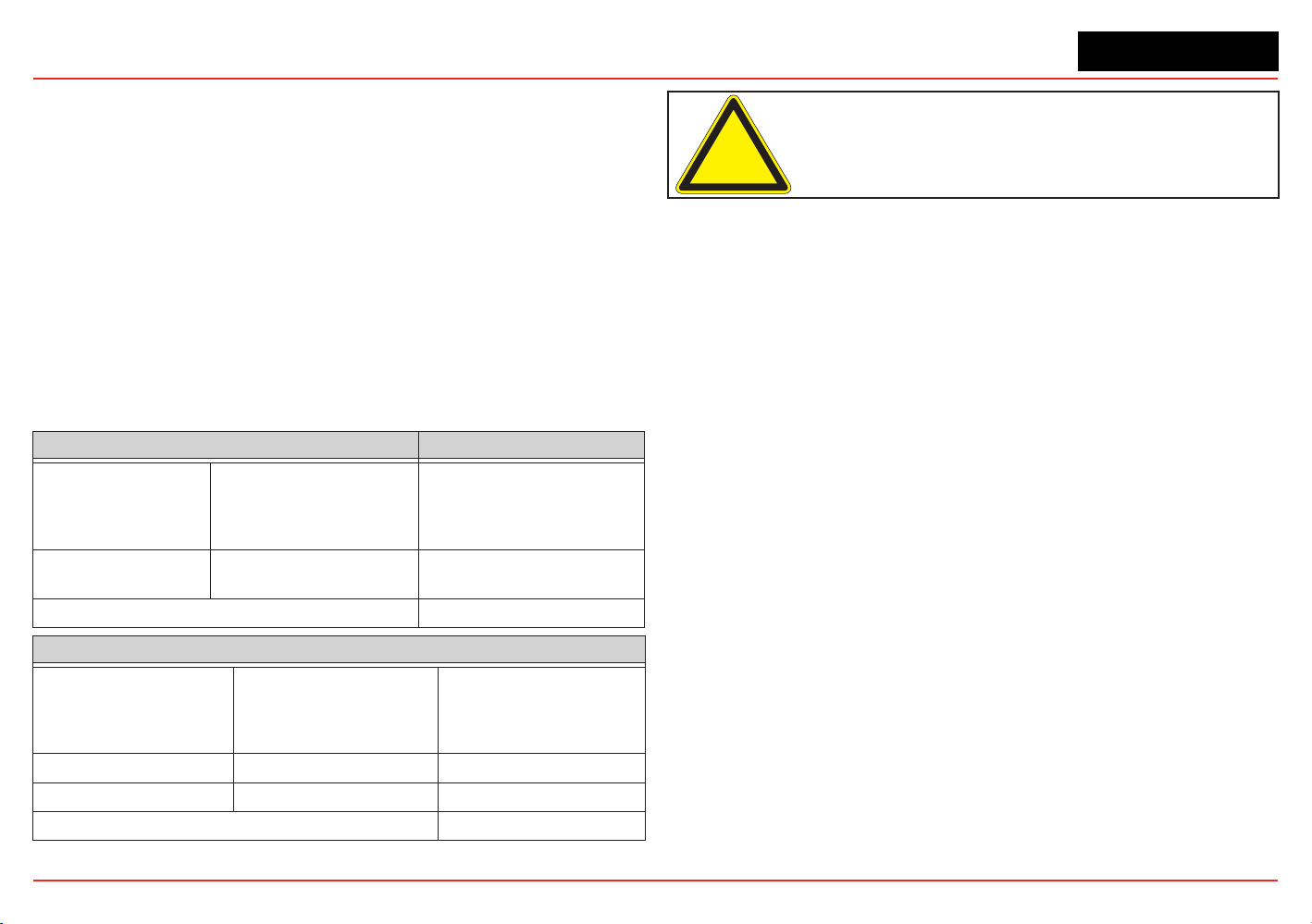
The XNX Universal Transmitter relies on 4-20mA output, refreshed
at least every two seconds (once per second is typical), in which
the output is proportional to the gas concentration.
XNX Universal Transmitter
Section 1 - Introduction 11
1.1.2 20 mA/HART
®
Output
All XNX Transmitters provide a 20mA Current Loop with HART
Source (3-Wire) or Isolated (4-Wire) electrical interface based on
installation requirements.
The 20mA current loop output provides an analog indication
of special states, a proportional output to gas concentration
and over range indication per the table below. In the event of
a simultaneous alarm and fault, an alarm condition will always
override a warning state.
Output Description* Notes
1.0 mA Fault
Special
State
Indication
2.0 mA
Warm-up
Inhibit
Bump Test
Calibration
3.0 mA Warning
4-20 mA Gas Concentration
21 mA Over Range
*Alarm conditions always take priority over faults and warnings.
HART Protocol provides digital communications with the XNX
Diagnostics. (See Appendix A HART Protocol for additional
information)
1.1.3 Communications
The XNX Universal Transmitter is registered
with the HART Communication Foundation.
The transmitter uses HART over 4-20mA as the standard
communications protocol. Additional optional communication
interfaces are available: relay communication, Modbus, or
Foundation Fieldbus. Each communication option has a
dedicated option board. For additional information, refer to
Section 1.3 Options.
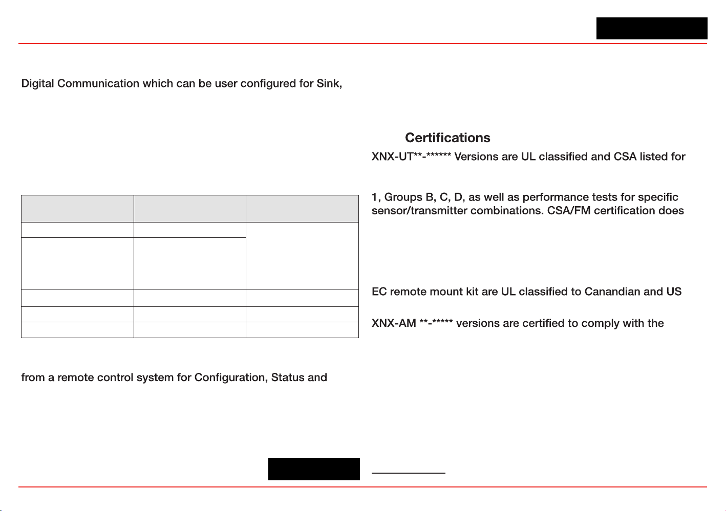
1.1.4
installation in Class I, Division 1, Groups A, B, C and D Hazardous
Locations. FM Approvals evaluation includes Class I, Zone
not cover daisy-chained XNX combustible gas transmitters, the
use of HART, Modbus, or Foundation Fieldbus protocols for
combustible gas performance. HART, Modbus, or Foundation
Fieldbus protocols can be used only for data collection or record
keeping with regards to combustible gas. The EC cartridge
2
and
standards.
European Community ATEX Directive and the prescribed
protection methods for installation in Potentially Explosive
Atmospheres.
and INMETRO approved (TÜV Rhineland) for compliance with
both U.S. and Brazilian standards.
See Section 6.2 for additional information on applicable
approvals by part number and Section 6.2.1 for marking.
2
“Cartridge” and “sensor” are used interchangeably in this document.
XNX-BT**.***** and XNX-UT**.***** versions are UL classified
XNX Universal Transmitter
Section 1 - Introduction
12
1.1.5 Patents
This table shows details about XNX-related patents.
Patents Applicable to the XNX Universal Transmitter
Patent
Number
Description Application
6,123,818 Reflex patent Implemented in XNX
6,251,232 Reflex patent Implemented in XNX
6,351,982 Flammable sensor housing XNX accepts this sensor
6,395,230 Pellistor Sensor used in XNX
7,225,661 Gas calibration adapter Applicable to XNX
7,716,962 Method of gas calibration Used to calibrate XNX ECC cartridges
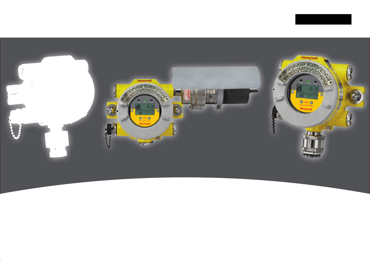
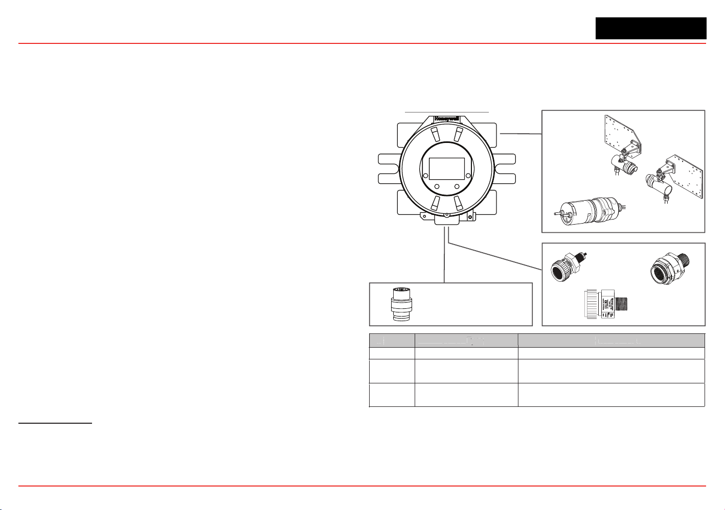
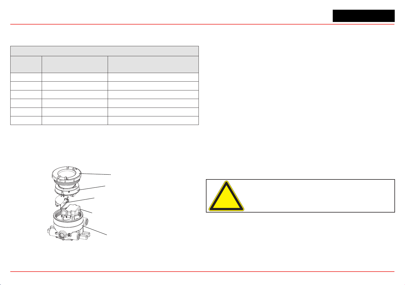
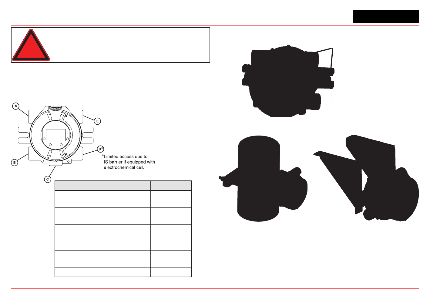
1.2 Product Overview
The XNX transmitter is comprised of the main parts shown
below.
Cover
Pod
Intrinsically Safe (IS) Barrier for
Optional Local HART Interface
Intrinsically Safe (IS) Barrier for
Electrochemical Sensor Interface
(when equipped)
Enclosure
Figure 2. XNX Exploded View
A complete description of XNX accessories can be found in
publication 1998-0807 XNX Universal Transmitter Parts List.
1.2.1 Enclosure
Available in either Stainless Steel or Aluminum, with 3/4” NPT
(UL/CSA or UL/ INMETRO) or M25 (ATEX/IECEx only) threaded
cable/conduit ports, the XNX Universal Transmitter enclosure is
explosion-proof and suitable for use in -40°F to +149°F (-40°C to
+65°C) operating conditions. A 5-coat marine nishing process
provides the highest degree of corrosion protection. For more
information on performance specications, see Section 6 -
Specications.
The XNX enclosure is equipped with ve threaded cable/conduit
ports providing functional and exible congurations based on
sensor and option choices. See Figure 5 for cable/conduit port
assignments and restrictions.
Stopping plugs (HA PN# 1226-0257 or 1226-0258) have been
provided to seal unused cable/conduit ports and have been
Agency evaluated/approved for use with the XNX enclosure
only. The number of stopping plugs varies among available
congurations.
Caution: The stopping plugs are for use only with the XNX Transmitter
and should not be used with any other device.
Mounting lugs integral to the XNX enclosure allow easy instal-
lation on a at surface or 2”-6” (50-150mm) diameter pipe with
the optional Pipe Mount Kit or Ceiling Mount Bracket Kit.
XNX Universal Transmitter
Section 1 - Introduction
13
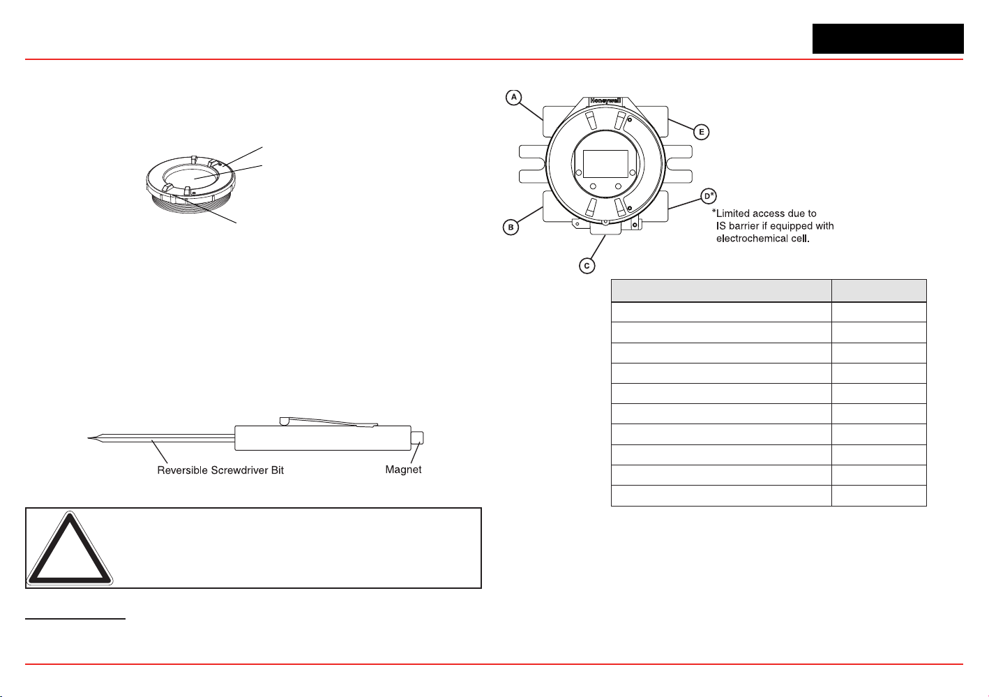
1.2.2 Cover
The transmitter cover is supplied in the identical material
specied for the enclosure.
Cover Lock Screw, requires a
2mm hex key (included)
Tempered Glass Window
Cover
Figure 3. XNX components
A tempered glass window requires the use of the supplied magnetic
wand/screwdriver to activate the four user interface switches that
are located on the front of the display module. This allows for non-
intrusive setup and operation.
A locking screw integrated into the cover provides positive
locking that can be removed by using the supplied 2mm hex
key
3
.
Figure 4. Magnetic Wand/Screwdriver
Note: When attaching the cover or stopping plugs, coat the threads
to prevent corrosion.
3
See the
XNX Universal Transmitter Parts List
(document 1998-0807) for a de-
scription of all of the parts that are shipped with the transmitter.
While relay wiring can use any available
cable/conduit port in the XNX enclosure,
do not use the same cable/conduit port for
both relay reset and relay signal lines to
avoid electrical noise.
Option Position
Local HART Option B
XNX Electrochemical Sensor - Local/Remote C
MPD, 705 Series, Sensepoint Series C
Searchpoint Optima Plus A or E
Searchline Excel Typically C
Remote Sensor Connection (except EC ) Any remaining
Searchpoint Optima Plus - Remote Any remaining
Modbus Any remaining
Relays Any remaining
Power Any remaining
Figure 5. XNX Universal Transmitter Cable/Conduit Port Assignments
XNX Universal Transmitter
Section 1 - Introduction
14
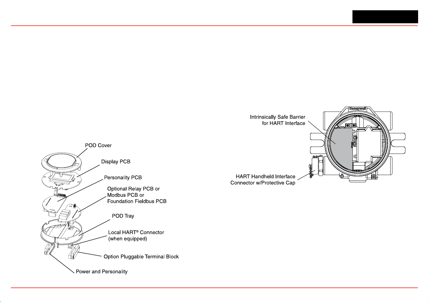
1.2.3 POD
The POD (Personality, Options, and Display) encloses circuit
boards for the personality module, optional interfaces, and
display.
The personality module, or circuit board, determines the
transmitter behavior based on the sensor type attached to
the transmitter (electrochemical cell, catalytic bead sensor, or
infrared) and provides the necessary interface. Connection to the
attached sensor is made through the sensor connector accessed
via a slot in the POD housing.
The optional communication boards vary depending on the
option selected when ordered. Only one of the three available
interface options (relays, Modbus, or Foundation Fieldbus) can
be attached to the XNX transmitter.
Figure 6. POD, exploded View
1.3 Options
1.3.1 Local HART
Available with any sensor technology or personality, an external
access to the HART interface in the XNX transmitter is provided.
An intrinsically safe (IS) barrier inside the transmitter gives the
user full control using a hand-held interrogator for programming
and conguration. The external interface is installed in the lower
left cable/conduit port of the transmitter and is intrinsically safe.
For more information, see Appendix A - HART Protocol.
Figure 7. XNX Universal Transmitter with HART Interface IS Barrier
1.3.2 Relays
The relay option (XNX-Relay) provides 3 form “C” (SPDT)
normally open/normally closed (NO/NC) contacts for alarm
and fault indication. A remote reset input is provided (TB4).
Momentarily closing the the circuit between the pins of TB4
performs the same function as the Reset Alarms & Faults
command.
The XNX transmitter has three relays: relay 1 is for alarm level
1, relay 2 is for alarm level 2, and relay 3 is for faults and special
XNX Universal Transmitter
Section 1 - Introduction
15
states. Two alarm levels can be set, allowing, for example, a level
1 alarm for the immediate area when a certain gas concentration
is detected and a plant-wide level 2 alarm when a greater gas
concentration is detected.
The maximum refresh rate of the relays is 2 seconds. See Set
Alarm Values for more information.
1.3.3 Modbus
The optional Modbus interface allows the XNX to connect to
a bus of devices and transmit data to PLCs or controllers.
(For more information, see the Modbus
Protocol Manual).
Connections to the XNX are made through a pluggable terminal
block on the Modbus interface circuit board. Modbus RTU
protocol uses ASCII/Hex protocols for communication.
Note: POD options are either relay, Modbus, or Foundation Fieldbus.
1.3.4 Foundation Fieldbus
Foundation Fieldbus is a digital communication system which
supports several types of messages. Unlike many traditional
systems which require a set of wires for each device, multiple
Foundation Fieldbus devices can be connected with a
single set of wires. Foundation Fieldbus overcomes some
of the disadvantages of proprietary networks by providing a
standardized network for connecting systems and devices.
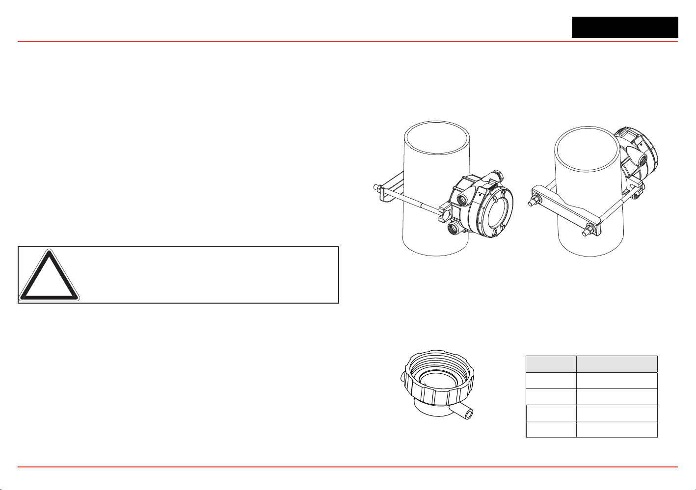
1.3.5 XNX Accessories
Pipe Mount Kit
The Pipe Mount kit (1226A0358) allows the XNX to be mounted
to pipe from 2”-6” (50-150mm) in diameter. The kit includes the
pipe mount bracket, two carriage bolts, nuts, and lock washers.
Figure 8. Pipe-mounted XNX Transmitters
Calibration Gas Flow Adapter
The calibration gas ow adapter is used to apply calibration
test gas to the sensor. It attaches to the bottom of the sensor
and can be tted without removing the weatherproof cover. See
Section 3 - Calibration for further details on gas calibration.
Sensor Flow Adapter P/N
XNX EC S3KCAL
MPD 1226A0411
Sensepoint 02000-A-1645
705 00780-A-0035
XNX Universal Transmitter
Section 1 - Introduction
16
Weatherproof Cap
The weatherproof cap protects XNX sensors from harsh weather.
Sensor Weatherproof Cap P/N
XNX EC
Included
MPD
02000A1640
Sensepoint
02000-A-1640
705
00780-A-2076
MPD-*TCB1
SPXCDWP (included)
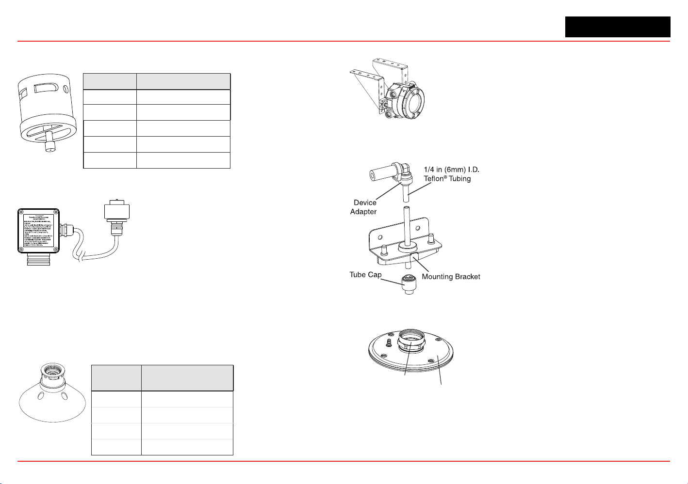
Remote Sensor Mounting Kit for XNX EC Sensors
The remote sensor mounting kit
(S3KRMK) allows XNX EC sensors to
be remotely mounted via an IS cable
kit, up to 50 feet (15 meters) from the
transmitter. The kit includes 50 feet of
shielded cable, cable glands, and
remote terminal box. The cable can be
cut to the required length then terminated at the remote terminal
box.
Collecting Cone
The collecting cone improves detection of lighter-than-air gases
such as hydrogen and methane.
Sensor Collecting Cone P/N
XNX EC S3KCC
MPD 02000-A-1642
Sensepoint 02000-A-1642
705 02000-A-1642
Ceiling Mount Bracket Kit
The optional Ceiling Mount Bracket Kit
(1226A0355) allows the XNX Transmitter to be
mounted to the ceiling. The kit includes two
stainless steel ceiling mount brackets, bolts,
and nuts.
Remote Gassing Kit
The Remote Gassing Kit
(1226A0354) enables gas to be
applied remotely for performing
functional response checks (bump
tests). The kit Includes: 50’ Teon
®
tubing, a mounting bracket, a tube
cap, and device adapters in 1/4”
and 1/8” (6.3 mm and 3.2 mm) ID to
attach to bump test ports on the
weatherproof cap of the device.
Duct Mount Kit
1226A0382 MPD Adapter Ring
S3KDMK EC/MPD Duct Adapter Kit
The duct mounting kit (S3KDMK) can
be used with the EC sensor to allow
detection of O
2
, CO, H
2
and H
2
S gases
in ducts. When combined with the
MPD Interface Adapter (1226A0382),
the duct mounting kit can
accommodate the MPD to detect ammable gases in a duct
application. The duct mount kit includes the adapter, gasket and
required fasteners. The MPD Interface Adapter includes only the
adapter and requires the S3KDMK duct mount kit.
XNX Universal Transmitter
Section 1 - Introduction
17
Weather Protector
The Extreme Weather Protector (SPXCDWP) is
designed to protect the sensor from
environmental conditions in outdoor exposure
applications.
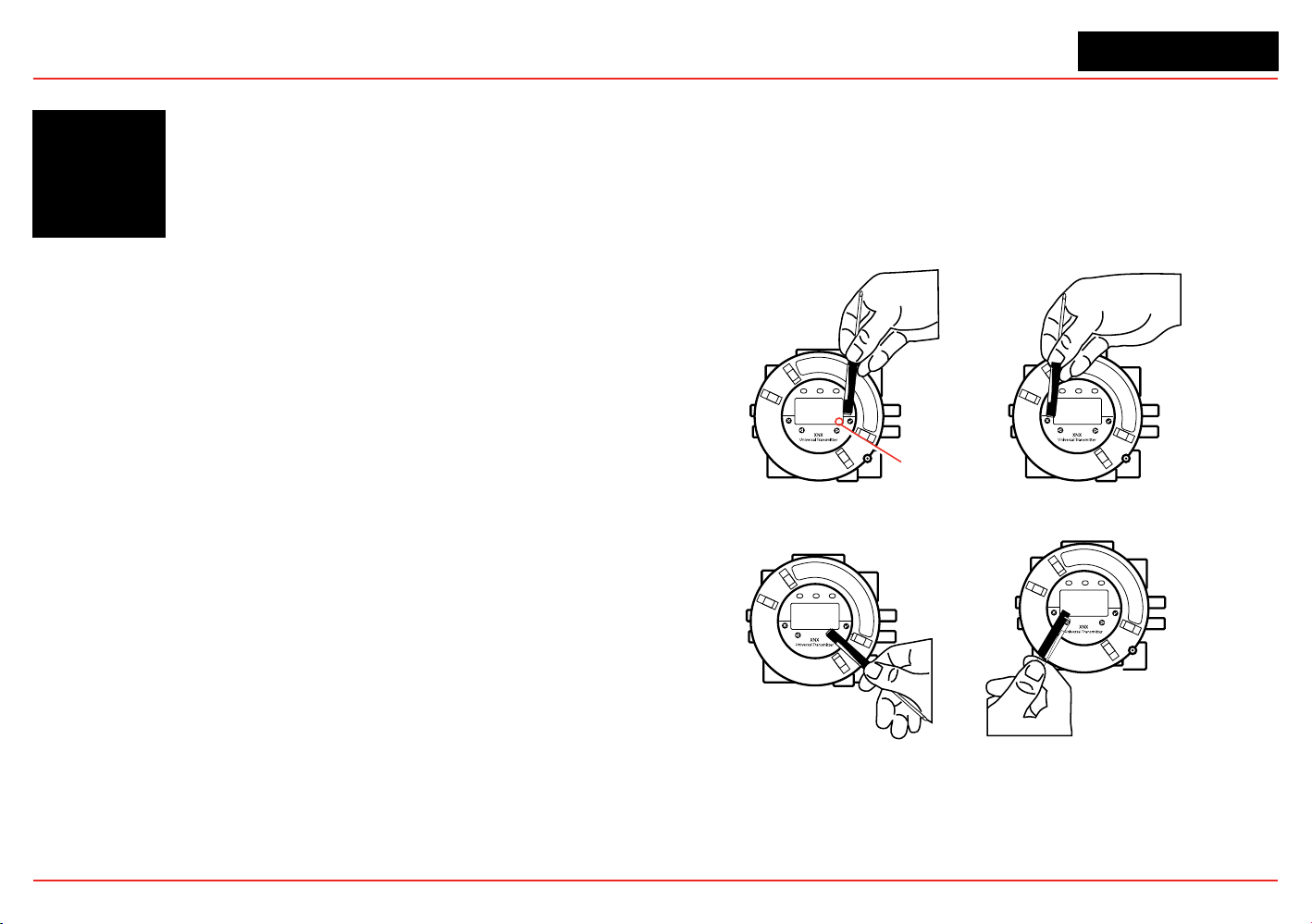
1.4 The XNX Front Panel
The XNX Transmitter uses magnetic switches to enable non-
intrusive operation. To activate a magnetic switch, hold the
magnetic end of the screwdriver up to the glass window and
slowly swipe the magnet directly over the shaded area.
For best results, hold the screwdriver as illustrated in Figure 9.
Enter/Accept
Escape/Back
Move Right/Increment Value Move Left/Decrement Value
Switch Actuation
Visual Indicator
Figure 9. Using the magnetic wand
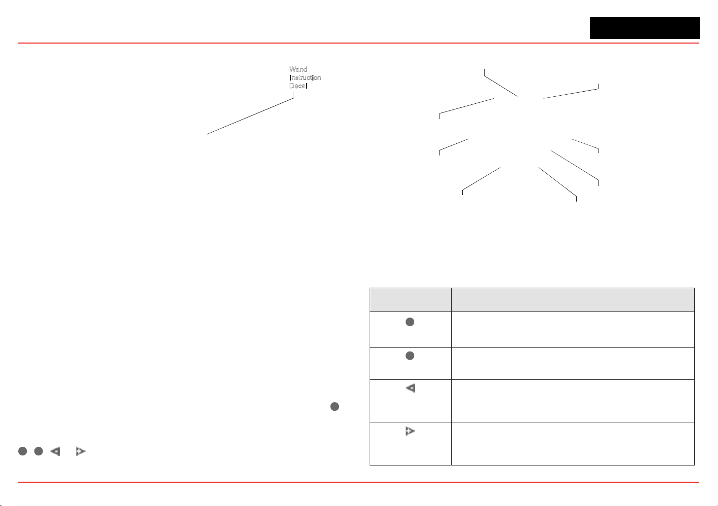
A decal illustrating the proper method for actuating the magnetic
switches is placed on the POD of each transmitter.
XNX Universal Transmitter
Section 1 - Introduction
18
Wand
Instruction
Decal
Figure 10. Operation decal
The switch is actuated by the ux lines between the poles of the
magnet. This actuation method provides the most consistent
response.
A visual indication of the switch actuation will appear in the
lower right corner of the XNX display each time the switch is
activated.
In some menus where displayed values can be changed, the
magnet must be swiped over the switch to cause the numeral on
the display to advance through the available values. Use the
✖
switch to return to a previous menu or eld.
For the purposes of this manual, the instruction to use
✓
,
✖
, or , means to activate the relevant magnetic switch as
described above.
Power LED (green)
Alarm LED (red)
Fault LED (yellow)
Escape
Move Left
Decement Value
Move Right
Increment Value
Switch Actuation
Visual Indicator
Enter/Accept
Figure 11. Front panel display of the XNX transmitter
1.4.1 Controls and Navigation
Command Description
✓
Enter/Accept
The Enter/Accept switch is used to access menus,
accept changes and to answer “yes” to system
prompts.
✖
Escape/Back
The Escape/Back switch is used to return to previous
menus or to answer “no” to system prompts.
Move Left/
Decrement Value
The Left/Decrement arrow is used to move through
menu options or decrement values when entering text
or numbers.
Move Right/
Increment Value
The Right/Increment arrow is used to move through
menu options or increment values when entering text or
numbers.
XNX Universal Transmitter
Section 1 - Introduction
19
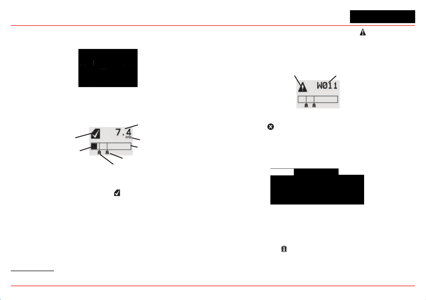
1.4.2 The General Status Screen
\
Figure 12. General Status screen
4
The General Status Screen shows the status of the XNX
Transmitter.
Status Indicator
Current Concentration Level
(Numeric)
Alarm 2 Set Point
Alarm 1 Set Point
Current Concentration Le
vel
(Bar Graph)
Full Scale
Concentration Units
Figure 13. General Status screen, normal operating mode
The Normal Operating Mode icon indicates proper operation.
The XNX display also shows the concentration level of the
target gas in two ways. In the rst, a numeric value is shown in
the upper right corner of the display in the units selected (ppm,
%LEL, %VOL). The second concentration display is shown in
the form of a bar graph representing the current concentration
against full scale and in relation to the dened alarm levels. For
more information on setting range and alarm levels, see Section
2.6.2 Range/Alarm Settings. See Section 6.2.2, Section 6.2.3,
and Section 6.2.4 for negative drift and zero deviation values.
4
The LCD screen’s refresh rates are 500 milliseconds (when the LCD heater is off) and 1 second
(when the heater is on).
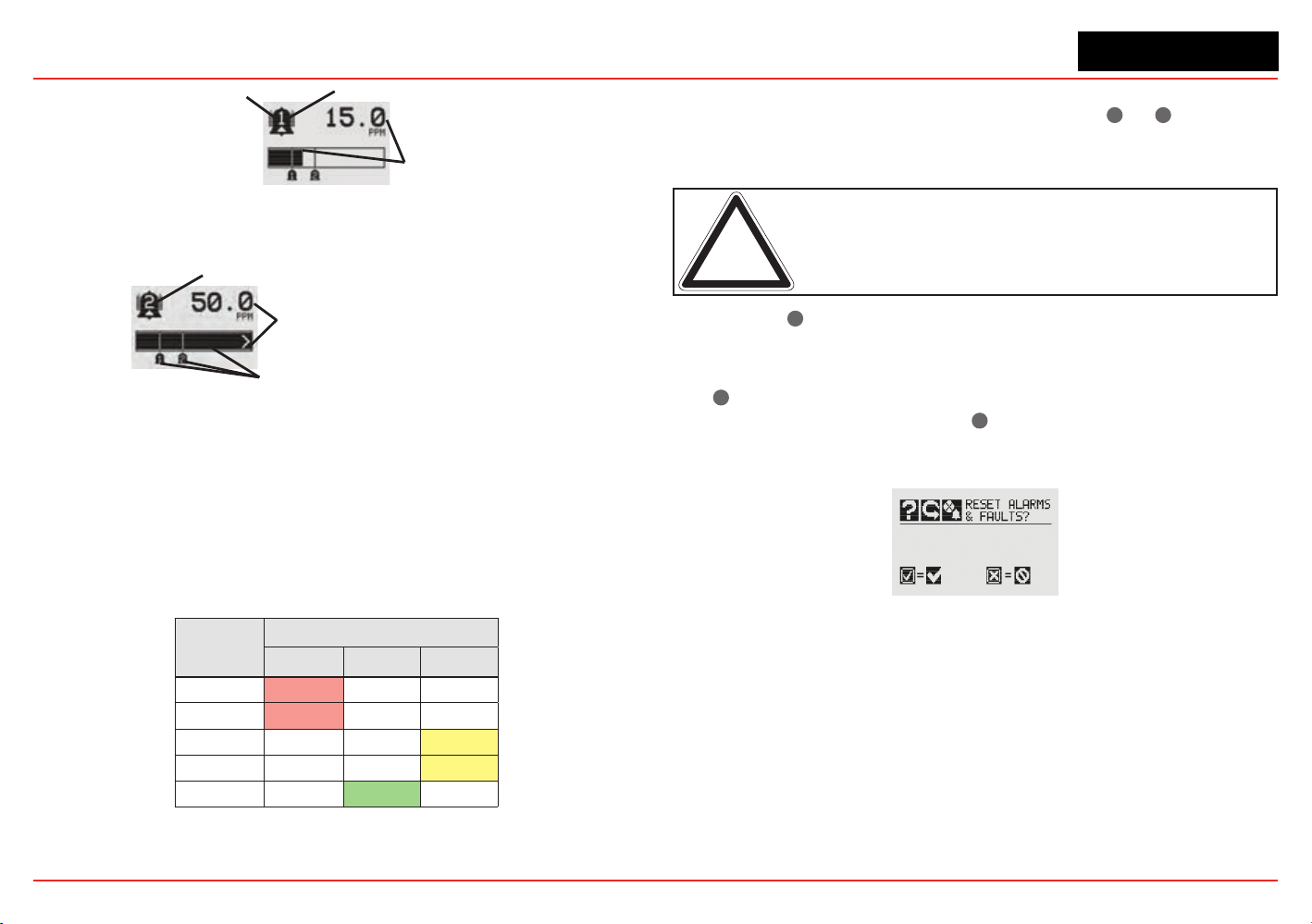
When a warning is triggered, the warning icon appears and
information is displayed on the General Status Screen. The
information displayed alternates between screens displaying
the gas concentration and the warning code. See Section 5 -
Warnings/Faults for more warning code information.
Warning Code
Warning Icon
Figure 14. General Status Warning detail
If the Fault icon is displayed, a fault condition has been
triggered and the display will alternate between the target gas
concentration and the fault code. See Section 5 - Warnings/
Faults for more fault code information.
Fault Icon
Fault Code
Figure 15. General Status Fault detail
In the event of multiple warnings or faults, the user can view all
messages with the transmitter’s Event History function.
When an Alarm icon
is displayed, the target gas concentration
exceeds one or both preset alarm levels. The General Status
Screen displays the gas concentration and the alarm level
exceeded.
XNX Universal Transmitter
Section 1 - Introduction
20
Target Gas
Concentration
Alar
m Icon
Alarm Level Triggered
Figure 16. General Status Alarm detail
In an over range condition, the alarm icon will display and the target gas
concentration bar graph and alarm setpoints will ash.
Full Scale
Concentration
Alarm Level Triggered
Concentration Bar, Alar
m Setpoints Flash
Figure 17. General Status Over Range detail
Negative values are not displayed and do not appear on the
4-20 mA output, but they are indicated by faults or warnings
when preset thresholds are exceeded. (See zero deviation in
Section 6.1.1)
In addition to the graphic alarm, fault, and warning indicators,
the LEDs on the front panel ash in these patterns based on the
condition:
Condition
LED
1
Red Green Yellow
Alarm 1 Solid
Alarm 2 Flashing
Warning Solid
Fault Flashing
2
Health Flashing
1
The refresh rate of the LEDs is 0.5 second.
2
Special states (Warmup, Inhibit) are not indicated by the Fault LED.
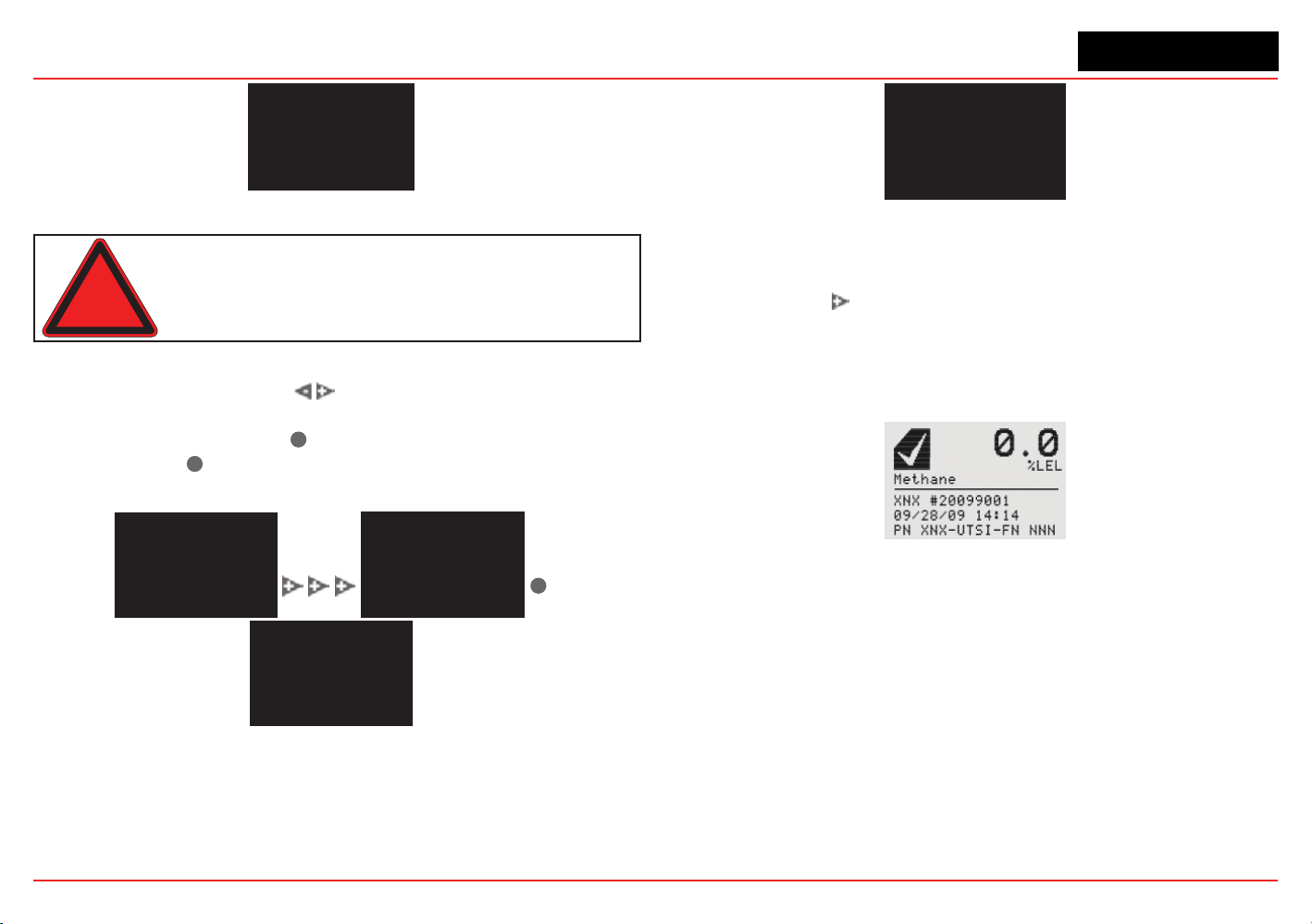
1.4.3 Entering the Menu Structure
Swiping the magnet over the magnetic switch
✓
or
✖
allows the
user to reset faults or alarms, display current settings, or make
adjustments to the device.
Note: If the Easy Reset option is set to Lock, alarms and faults
cannot be reset without logging in or entering a passcode. For more
information, see Section 2.5.1 Configure Security.
Swiping the
✖
or “escape” magnetic switch activates the Alarm
Re-set screen and allows alarms to be silenced and faults to be
reset.
The
✓
switch resets all alarms and faults and returns to the
General Status Screen. Use the
✖
switch to return to the
General Status Screen without resetting the alarms and faults.
Figure 18. Alarm Reset screen
Two authorization levels control access based upon the security
level of the user: Level 1 (routine maintenance) and Level 2
(technician and password administrator). The default passcodes
for both levels are “0000” and must be reset after installation
to control access (see Section 2.5.1 Configure Security). In
general, access to neither security level restricts the user to
viewing the transmitter’s display. If desired, the Easy Reset from
Main Status option
allows alarm and fault resets without requiring
access to either security level.
XNX Universal Transmitter
Section 1 - Introduction
21
Figure 19. Passcode screen
Warning: The factory-set passcodes must be reset to prevent
unauthorized access to the transmitter’s menus.
When the Passcode Screen is displayed, the rst passcode
digit is highlighted. Use the switches to increment or
decrement through the values. Once the correct value is
displayed for the rst digit,
✓
accepts the value and moves to
the next digit or
✖
moves to the previous digit of the passcode.
✓
Figure 20. Entering the passcode
Repeat for each of the remaining digits in the passcode. If the
passcode is not entered correctly, the Invalid Passcode screen
is displayed and the user is returned to the General Status
screen.
Figure 21. Invalid Passcode screen
1.4.4 Displaying Transmitter Information
While in the General Status display, swipe the magnet over the
magnetic switch
to display information about the transmitter.
The General Status display will replace the bar graph in the
lower portion of the screen with the unit’s serial number, the
date and time, and the unit’s part number.
Figure 22. General Status Screen with Unit Information
XNX Universal Transmitter
Section 1 - Introduction
22
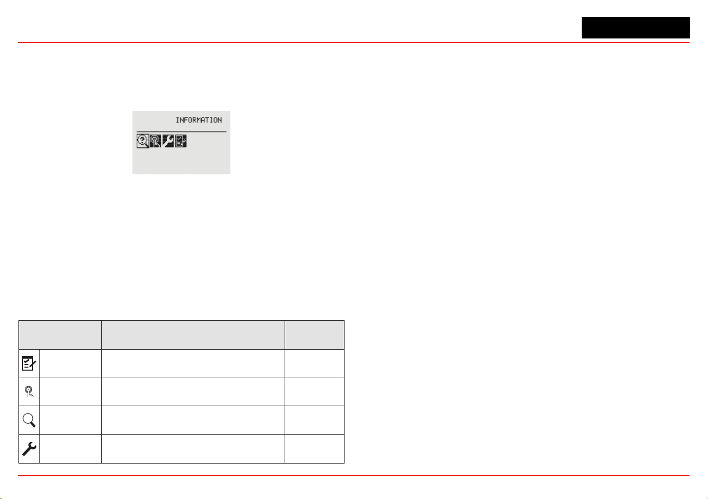
1.5 Main Menu
Once the proper passcode has been entered, the transmitter
displays the Main Menu.
Figure 23. The Main Menu
From the Main Menu, a Level 1 user can:
• display the current settings/conguration
• test the transmitter
• calibrate and bump test the transmitter
• congure the unit for language, date and time
The Main Menu consists of these options:
Menu Description
See
Section...
Congure
Provides access to settings to configure the
transmitter and connected devices
2.5.1
Test
Provides access to tools and settings to allow
simulation of gas events to test the system
2.6.1
?
Information
Displays current settings for the XNX transmitter
including optional relays and Modbus
2.6.2
Gas
Calibration
Displays the XNX interface to calibrate sensors
attached directly to the transmitter
3.1
XNX Universal Transmitter
Section 1 - Introduction
23
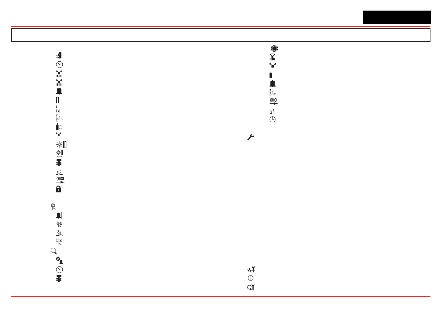
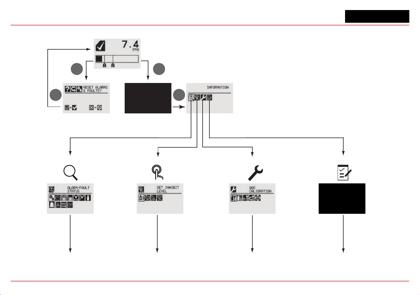
1.5.1 XNX Menu Map
Status Display
Passcode Display
Main Menu
Alarm/Fault Reset
Display
?
1. Information Mode 2. Test Mode
3. Calibration Mode
4. Configuration Mode
3
6
33
Continued
on page 24
Continued
on page 25
Continued
on page 25
Continued
on page 26
XNX Universal Transmitter
Section 1 - Introduction
24
Information Mode
Alarm/Fault Status
Alarm/Fault
Conrm Alarm/Fault Reset
Reset Alarm/Fault
Date & Time
Transmitter ID, Serial #, Revision
Transmitter Data
Transmitter Status
Transmitter Status
Sensor Type, Serial #, Revision
Sensor Data
Sensor Status
Sensor Status
Gas Name, ID, Range
Gas Data
Range Settings, Alarm Settings
Range/Alarm Settings
mA Level Settings
mA Level Settings
Relay Settings
5
Relay Settings
5 Optional relay only
Fieldbus Settings
6
Fieldbus Settings
Event History
Increment Next/Previous Event
Increment Next/Previous Hour
Increment Next/Previous Day
Increment Next/Previous Alarm
Increment Next Previous Fault
6
Optional Foundation Fieldbus and Modbus only
XNX Universal Transmitter
Section 1 - Introduction
25
Test Mode
Inhibit
Enable/Disable Inhibit
Force mA Output
Select Current: 0 to 22 mA
Accept
Force Relay
7
Select Relay 1
Select Relay 2
Select Relay 3
Accept
Alarm/Fault Simulation
Alarm 1 Simulation
Alarm 2 Simulation
Warning Simulation
Fault Simulation
7 Optional relay only
Calibration Mode
Gas Calibration
Enter Span Gas Concentration (Oxygen)
Enter Span Gas Concentration (Not Oxygen)
Bump Test
mA Output Calibration
Adjust 4 mA Output
Adjust 20 mA Output
Soft Reset
8
Align Excel
9
8 Searchpoint Optima and Searchline Excel only
9
Searchline Excel only
XNX Universal Transmitter
Section 1 - Introduction
26
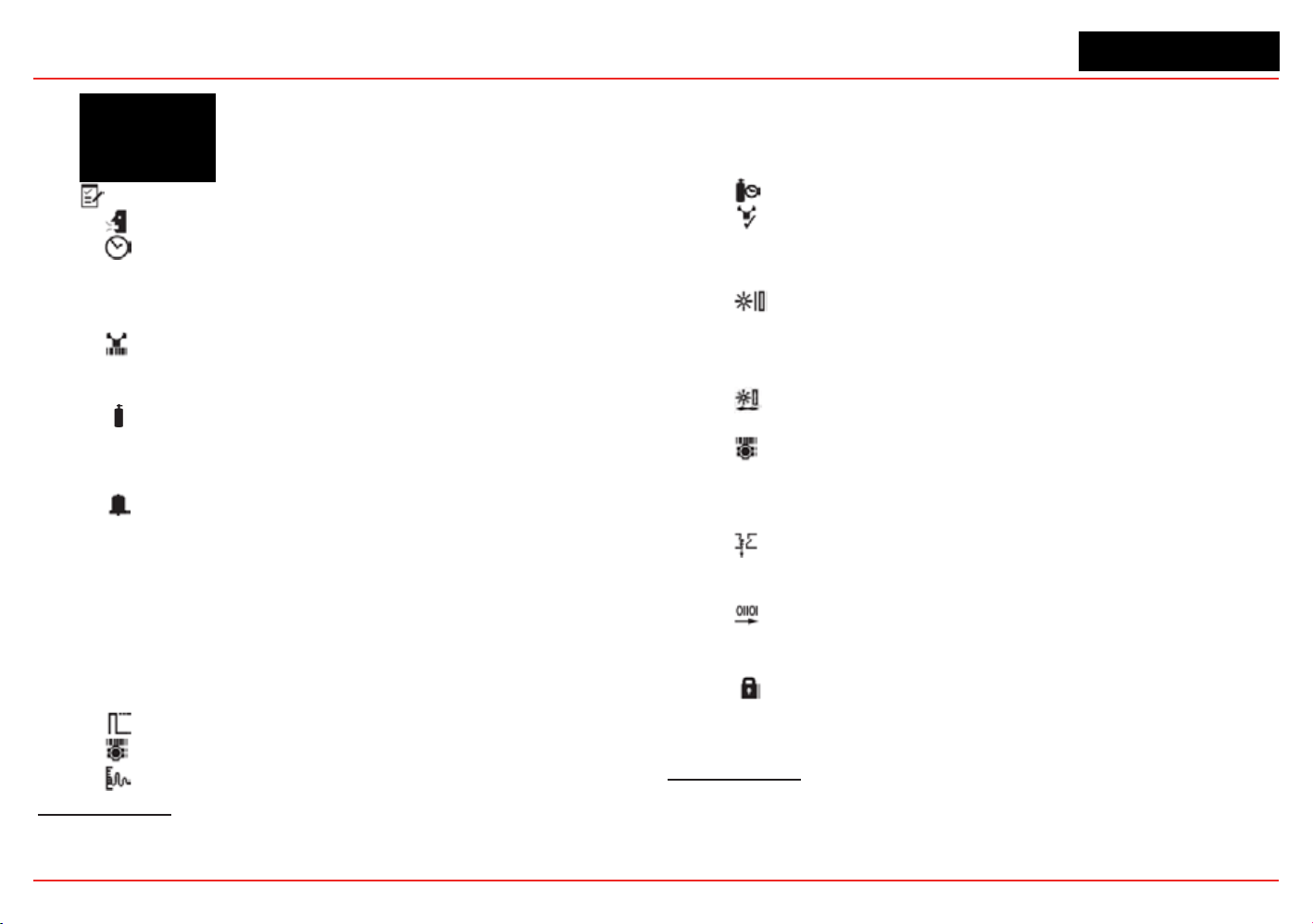
Conguration Mode
Select Language
Set Date & Time
Set Date Format
Set Year, Month, Day
Set Hours, Minutes, Seconds
Sensor Type Selection
Set mV Sensor Type
10
Set mA Sensor Type
11
Gas Selection
Changing the Gas or Units Name
Gas Selections and Alarm Limits Based on mV
Sensor Type
Range & Alarms
Set Range
Alarm 1 Type
Alarm 1 Setpoint
Alarm 1 Latching or Non-latching
Alarm 2 Type
Alarm 2 Setpoint
Alarm 2 Latching or Non-latching
Selecting the Numeric Format
Latching/Non-latching
Change Meas. Units
12
mA Output Levels
Change mA for Inhibit
10 Catalytic bead sensor only
11 Searchpoint Optima and Searchline Excel only
12 ECC and mV only
Change mA for Warning
Change mA for Overrange
Change mA for Low Signal
Change mA for Blocked Beam
Set Calibration Interval
Accept New Sensor Type
13
Information screen identifying previous sensor and
new sensor
Screen displays new type and old type
Set Beam Block
14
Select Beam Block Threshold
Select Time to Beam Block
Select Time to Fault
Set Path Length
15
Set New Path Length
Congure Unit ID
Edit ID
Clear ID
Default ID
Relay Options
16
Select A1
Select A2
Fieldbus Options
17
Change Fieldbus Address
Change Fieldbus Speed
Security
Reset and LVL1
LVL1 Code
LVL2 Code
13 Electrochemical and catalytic bead sensors only
14 Searchline Excel only
15 Searchline Excel only
16 Optional relay only
17 Optional Foundation Fieldbus and Modbus only

XNX Universal Transmitter
XNX Universal Transmitter Technical Manual
27
2 Installation and
Operation
XNX Universal Transmitter
Section 2 - Installation and Operation
28
2.1 Mounting and Location of Sensors
Caution: Locate transmitters and sensors in accordance with
relevant local and national legiislation, standards, and codes of
practice.
The placement of sensors should be determined following the
advice of experts having specialist knowledge of gas dispersion,
experts having knowledge of the process plant system and
equipment involved, and safety and engineering personnel. The
agreement reached on the location of sensors should be
recorded. Consider these factors when locating gas sensors:
• possible damage caused by natural events such as rain or
ooding
• ease of access for functional testing and servicing
• how escaping gas may behave due to natural or forced air
currents.
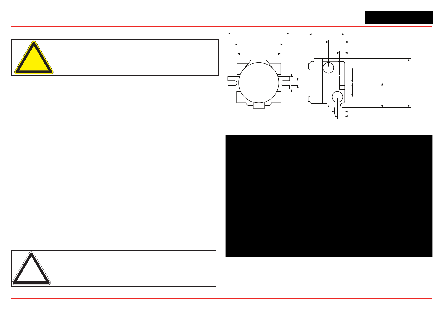
2.1.1 Mounting the XNX
®
Universal Transmitter
The transmitter can be mounted in a number of ways using the
integralmountingtabs.Thetransmittercanbeattachedtoat
wall surfaces or to Unistrut
®
.
With the optional Pipe Mount kit,
the unit can be mounted to pipe of diameter 2” to 6” (50 to
150mm). A ceiling mount bracket kit (1226A0358) is also
available.
Note: Agency certifications require that EC and mV sensors face
down. Optima sensors must be mounted horizontally.
1.67"
42.41 mm
5.6"
124.24 mm
6.00"
15.4 mm
7.75"
196.85 mm
4.48"
113.8 mm
0.625"
15.88mm
2.054"
52.18mm
0.945"
24mm
1.2"
31.75mm
1.768"
44.90 mm
3.176"
80.67 mm
1.768"
44.90 mm
0.55"
14.35 mm
6.138"
158.75mm
Figure 24. XNX Universal Transmitter mounting dimensions and clearances
XNX Universal Transmitter
Section 2 - Installation and Operation
29
Warning: When the transmitter is equipped with the optional
Remote Mount Kit, the remote sensor must be securely mounted in
a fixed position. The Remote Sensor kit is not intended to be used as
a hand-held sensor.
Thetransmitterisconguredwithvecable/conduitportsbuilt
into the housing for wiring and mounting sensors. Figure 25
provides the guidelines to proper installation of the XNX.
While relay wiring can use any
availablecable/conduitportin
the XNX enclosure, do not use
thesamecable/conduitportfor
both relay reset and relay signal
lines to avoid electrical noise.
Option Position
Local HART
®
Option B
XNX Electrochemical Sensor - Local/Remote C
MPD, 705 Series, Sensepoint Series C
Searchpoint Optima Plus A or E
Searchline Excel Typically C
Remote Sensor Connection (except EC ) Any remaining
Searchpoint Optima Plus - Remote Any remaining
Modbus Any remaining
Relays Any remaining
Power Any remaining
Figure 25. XNX Universal Transmitter cable/conduit port assignments
Integral Mounting Lugs
Figure 26. XNX Universal Transmitter mounting lugs
Figure 27. Optional pipe and ceiling mounts
XNX Universal Transmitter
Section 2 - Installation and Operation
30
2.2 Wiring the XNX Transmitter
The XNX transmitter is available in sensor technologies, or
personality options, which support a variety of sensors and
applications. Each of the personalities use dedicated interface
boards. Pluggable terminal blocks are used for easy connection
and service. The personality boards and optional communication
interfaces are enclosed in plastic housings comprising the
electronics POD (Personality, Options, and Display). The
Personality circuit board determines the XNX behavior based on
the sensor type attached to the XNX interface (Figure 35). See
Specicationsfordriftandzerodeviationvalues.
ThistableillustratesthethreeXNXtransmittercongurations
and the sensors each support.
XNX IR Personality XNX EC Personality
Searchline Excel
Searchpoint Optima Plus Local/
Remote
XNX EC Sensor
Generic mA Sensors XNX EC Sensor Remote Mount Kit
XNX mV Personality
705 Local / Remote MPD Local (cat bead and IR) Sensepoint Local / Remote
705HT Local / Remote MPD Remote Sensepoint PPM Local/Remote
Sensepoint HT Remote
Figure 28. XNX Transmitter personalities
Caution: Before wiring the transmitter, confirm that the correct
personality and communication boards are installed.
2.2.1 General Wiring Considerations
For proper operation of the XNX Universal Transmitter and
sensor technologies, consideration of wiring-induced voltage
drops, transient electrical noise, and dissimilar earth ground
potentials is imperative in the design and installation of the
system.
EMI note for applications using shielded cable: Cable
shield must provide 90% coverage of the wiring. Cable
shield terminations must be made at the cable glands
with suitable EMI-type glands. Avoid terminating
cable shields at the earth ground lug inside the XNX
enclosure.
Loading
When wiring for DC power, 4-20mA signal, remote wiring to
sensorsmustbesizedsufcientlytoprovideadequatevoltages
for the line length and the loads that will be used.
Isolation
Isolating power and signal carrying conductors is recommended.
Circuit Protection
Supply circuits must provide over current protection. Class 2
power supplies are required for 24 volt DC supply. Consider
inrush current in specifying any DC supply. Power supply range

XNX Universal Transmitter
Section 2 - Installation and Operation
31
is 16 to 32 VDC for EC and mV versions, 18 to 32 VDC for
Searchpoint Optima Plus and Searchline Excel, and 16 to 32
VDC depending on the limitations of the device for the generic
4-20mA input.
Loads
The use of high inrush or inductive loads may affect the
performance of the transmitter. For best reliability use resistive
loads only.
2.2.2 Distance Considerations for Installation
Providing power to the transmitter is the factor that will
determine the maximum distance of the installation. The 4-20 mA
output signal will easily handle the distance back to the control
equipment.
The primary factors determining distance are the minimum oper-
atingvoltageofthetransmitterand/orsensor;themaximum
currentdrawofthetransmitter/sensor,theresistanceofthewire
used, the power supply voltage, and the current capacity of
power supply.
Anadditionalconsiderationisthetypeofinstallation;
specically,howmanytransmitters/sensorsaredrawingpower
from the same power supply and whether these transmitters are
using the same pair of wires (“daisy-chain”) or have their own
connections.
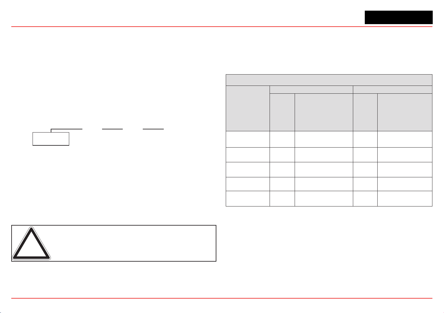
Types of Installations
There are three basic types of
installation:asingletransmitter;
multipletransmittersconnectedtoasinglepowersource;and
multipletransmittersconnectedina“daisy-chain”conguration.
Single Transmitter
This is the simplest type of installation. It consists of a single
XNX transmitter installation per power source.
Class 2
Power Supply
Class 2
Power Supply
Class 2
Power Supply
Figure 29. Single Transmitter Installation
Advantages:
• Maximum distance between power source and transmitter
• Smaller power source
• If a power source fails, only one monitoring point fails.
Disadvantage:
• Multiple transmitters require multiple power sources.
Multiple Transmitters Connected to a Single Power Source
This is two or more transmitters sharing a single power source
with each transmitter having its own dedicated wiring to the
power source.
Class 2
Power Supply
Figure 30. Multiple Transmitters Powered by a Single Power Supply
Advantages:
• Maximum distance between power source and
transmitters
XNX Universal Transmitter
Section 2 - Installation and Operation
32
• Fewer power sources.
Disadvantages:
• Larger power source will be needed
• If a power source fails, several monitoring points fail.
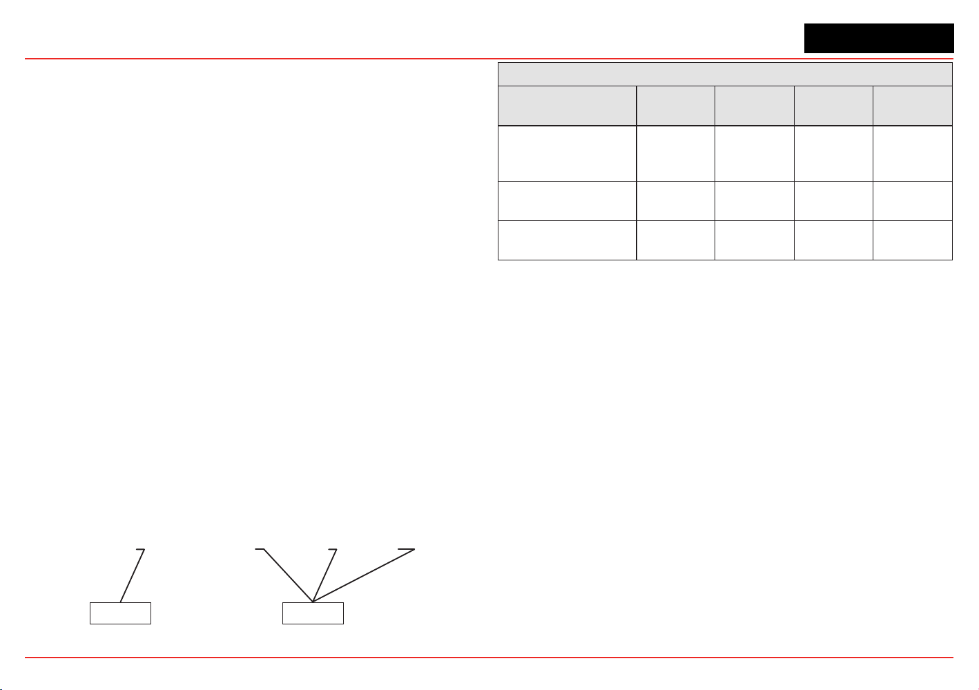
Multiple Transmitters Connected in a “Daisy-Chain”
Conguration
Thiscongurationconsistsoftwoormoretransmittersinstalled
in a line. The power connections are installed as an extension of
theprevioustransmitter,withthersttransmitterbeingtheonly
one actually wired to the power source.
Class 2
Power Supply
Figure 31. Daisy-chained transmitters from one power supply
Advantages:
• Less wire needed for installation
• Fewer power sources.
Disadvantages:
• Requires a larger power source
• Shorter distance between power source and transmitters.
• If a power source fails, several monitoring points fail.
Note: CSA/FM certification does not cover daisy-chained XNX combus-
tible gas transmitters.
Power Source Selection
For each type of installation, selection of power supply is
important. Power supplies are rated by voltage and power.
The nominal voltage for all XNX transmitters is 24V with the
power required depending on the number of points using the
same power supply.
XNX Universal Transmitter Maximum Power Consumption
Conguration
-40°C to +65°C -10°C to +65°C
HART
over
4-20mA
(watts)
HART over 4-20mA
with Relay, Modbus
®
, or
Foundation
TM
Fieldbus
(watts)
HART
over
4-20mA
(watts)
HART over 4-20mA
with Relay, Mod-
bus, or Foundation
Fieldbus
(watts)
XNX with toxic
sensors
5.1 6.2 3.4 4.5
XNX with catalytic
sensors
5.4 6.5 3.7 4.8
XNX with infrared
cartridge
5.4 6.5 3.7 4.8
XNX with Searchpoint
Optima Plus
8.6 9.7 6.9 8.0
XNX with
Searchline Excel
12.1 13.2 10.4 11.5
As a general guideline, the power supply should be capable
of providing more power than is required by the installation. A
10wattpowersupplyisneforasingleXNXmVwithcatalytic
sensor (6.5 watts required, see the following table) but is
inadequate for a single XNX IR with Searchpoint Optima Plus (10
watts required).
To determine the wattage required, add the maximum power
requirements of all the points that will share the power supply.
For example, consider a system with two XNX mV transmitters
with catalytic sensors (6.5 watts each) and one XNX IR with
XNX Universal Transmitter
Section 2 - Installation and Operation
33
Searchpoint Optima Plus (10 watts). A 25 watt power supply
would probably handle this installation, but a 30 watt power
supply would be a better choice.
Wire Selection
The type of wire used for connections has an effect on the
distance of the installation. This is because some of the voltage
is lost in the wire on the way to the transmitter.
Thinner wire (i.e., 18 AWG) will lose more voltage than thicker
wire (i.e., 12 AWG). The amount of voltage lost depends on how
muchpowerisbeingdrawnthroughthewire;morepowermeans
more loss. If too much voltage is lost in the wiring, there may
not be enough at the distant point to allow the transmitter to
operate.
Distance Chart for Single Transmitter Distances
For installations that have dedicated wiring between the
transmitter and the power supply, use the following chart. These
distances assume stranded wire is used. If multiple transmitters
are using the same power supply, make sure the power
supply wattage rating is high enough to power all transmitters
simultaneously.
Class 2
Power Supply
Class 2
Power Supply
OR
Figure 32. Single transmitter distances
Single Transmitter Distances
Conguration
18 AWG
[1.0 mm2]
16 AWG
[1.5 mm2]
14 AWG
[2.0 mm2]
12 AWG
[3.5 mm2]
XNX mV or EC
With Sensor
1140 feet
[347 meters]
1810 feet
[551 meters]
2890 feet
[880 meters]
4620 feet
[1408
meters]
XNX IR with
Searchpoint Optima Plus
660 feet
[201 meters]
1060 feet
[323 meters]
1690 feet
[515 meters]
2690 feet
[820 meters]
XNX IR with
Searchline Excel
550 feet
[168 meters]
890 feet
[270 meters]
1410 feet
[430 meters]
2260 feet
[690 meters]
XNX Universal Transmitter
Section 2 - Installation and Operation
34
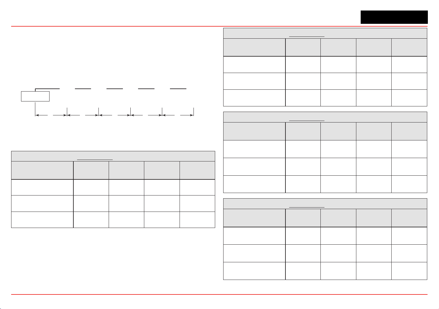
Daisy-Chained Transmitter Distances
Itisdifculttocalculatedistancesforthisconguration.There
are many factors to be considered: distance from control room
torsttransmitter,distancebetweentransmitters,sensortypes,
etc. A few scenarios are presented here to provide a base to
work from.
Class 2
Power Supply
“d”
“d”
“d”“d”“d”
Transmitter 1 Transmitter 2 Transmitter 3 Transmitter 4 Transmitter 5
Figure 33. Daisy-chained transmitter distances
1. Several transmitters equally spaced from themselves and
the power source.
2 Transmitters - Distance “d”
Conguration
18 AWG
[1.0 mm2]
16 AWG
[1.5 mm2]
14 AWG
[2.0 mm2]
12 AWG
[3.5 mm2]
XNX mV or EC
With Sensor
380 feet
[115 meters]
600 feet
[183 meters]
960 feet
[292 meters]
1540 feet
[469 meters]
XNX IR with
Searchpoint Optima Plus
220 feet
[67 meters]
350 feet
[106 meters]
560 feet
[170 meters]
900 feet
[274 meters]
XNX IR with
Searchline Excel
185 feet
[56 meters]
295 feet
[90 meters]
470 feet
[143 meters]
750 feet
[229 meters]
3 Transmitters - Distance “d”
Conguration
18 AWG
[1.0 mm2]
16 AWG
[1.5 mm2]
14 AWG
[2.0 mm2]
12 AWG
[3.5 mm2]
XNX mV or EC
With Sensor
190 feet
[58 meters]
300 feet
[91 meters]
480 feet
[146 meters]
770 feet
[234 meters]
XNX IR with
Searchpoint Optima Plus
110 feet
[33 meters]
175 feet
[53 meters]
280 feet
[85 meters]
450 feet
[137 meters]
XNX IR with
Searchline Excel
90 feet
[27 meters]
145 feet
[44 meters]
235 feet
[71 meters]
375 feet
[114 meters]
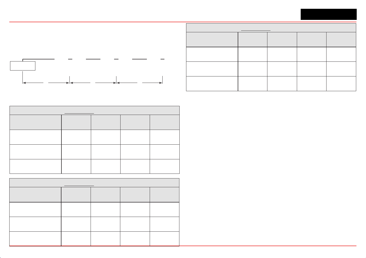
4 Transmitters - Distance “d”
Conguration
18 AWG
[1.0 mm2]
16 AWG
[1.5 mm2]
14 AWG
[2.0 mm2]
12 AWG
[3.5 mm2]
XNX mV or EC
With Sensor
110 feet
[33 meters]
180 feet
[55 meters]
290 feet
[88 meters]
460 feet
[140 meters]
XNX IR with
Searchpoint Optima Plus
65 feet
[20 meters]
105 feet
[32 meters]
165 feet
[50 meters]
270 feet
[82 meters]
XNX IR with
Searchline Excel
55 feet
[17 meters]
85 feet
[26 meters]
140 feet
[43 meters]
225 feet
[68 meters]
5 Transmitters - Distance “d”
Conguration
18 AWG
[1.0 mm2]
16 AWG
[1.5 mm2]
14 AWG
[2.0 mm2]
12 AWG
[3.5 mm2]
XNX mV or EC
With Sensor
75 feet
[23 meters]
120 feet
[36 meters]
190 feet
[58 meters]
300 feet
[91 meters]
XNX IR with
Searchpoint Optima Plus
45 feet
[13 meters]
70 feet
[21 meters]
110 feet
[33 meters]
180 feet
[55 meters]
XNX IR with
Searchline Excel
35 feet
[11 meters]
55 feet
[17 meters]
90 feet
[27 meters]
150 feet
[46 meters]
XNX Universal Transmitter
Section 2 - Installation and Operation
35
2. Several transmitters installed in pairs with each pair
equally spaced from the next pair and the power source.
These distances assume the paired transmitters are
installed within 10 feet [3 meters] of each other.
Class 2
Power Supply
“d”“d”“d”
Transmitters 1 and 2 Transmitters 3 and 4 Transmitters 5 and 6
Figure 34. Transmitters in pairs
2 Transmitters - Distance “d”
Conguration
18 AWG
[1.0 mm2]
16 AWG
[1.5 mm2]
14 AWG
[2.0 mm2]
12 AWG
[3.5 mm2]
XNX mV or EC
With Sensor
485 feet
[147 meters]
775 feet
[235 meters]
1230 feet
[292 meters]
1970 feet
[600 meters]
XNX IR with
Searchpoint Optima Plus
380 feet
[115 meters]
600 feet
[180 meters]
960 feet
[290 meters]
1540 feet
[470 meters]
XNX IR with
Searchline Excel
280 feet
[85 meters]
440 feet
[134 meters]
700 feet
[213 meters]
1130 feet
[344 meters]
4 Transmitters - Distance “d”
Conguration
18 AWG
[1.0 mm2]
16 AWG
[1.5 mm2]
14 AWG
[2.0 mm2]
12 AWG
[3.5 mm2]
XNX mV or EC
With Sensor
190 feet
[58 meters]
300 feet
[91 meters]
480 feet
[146 meters]
770 feet
[234 meters]
XNX IR with
Searchpoint Optima Plus
110 feet
[33 meters]
175 feet
[53 meters]
280 feet
[85 meters]
450 feet
[137 meters]
XNX IR with
Searchline Excel
90 feet
[27 meters]
145 feet
[44 meters]
235 feet
[71 meters]
375 feet
[114 meters]
6 Transmitters - Distance “d”
Conguration
18 AWG
[1.0 mm2]
16 AWG
[1.5 mm2]
14 AWG
[2.0 mm2]
12 AWG
[3.5 mm2]
XNX mV or EC
With Sensor
95 feet
[33 meters]
150 feet
[45 meters]
240 feet
[73 meters]
385 feet
[117 meters]
XNX IR with
Searchpoint Optima Plus
55 feet
[17 meters]
85 feet
[26 meters]
140 feet
[42 meters]
225 feet
[68 meters]
XNX IR with
Searchline Excel
45 feet
[14 meters]
70 feet
[21 meters]
115 feet
[35 meters]
185 feet
[56 meters]
Ensure that wiring is adequately protected from mechanical failure in
installation.Specicshortedoropencircuitconditionsofwiringtothe
MPD **I** sensors may result in full scale concentration readings prior
to, or preventing the internal diagnostic routines from identifying the
external installation fault.
XNX Universal Transmitter
Section 2 - Installation and Operation
36
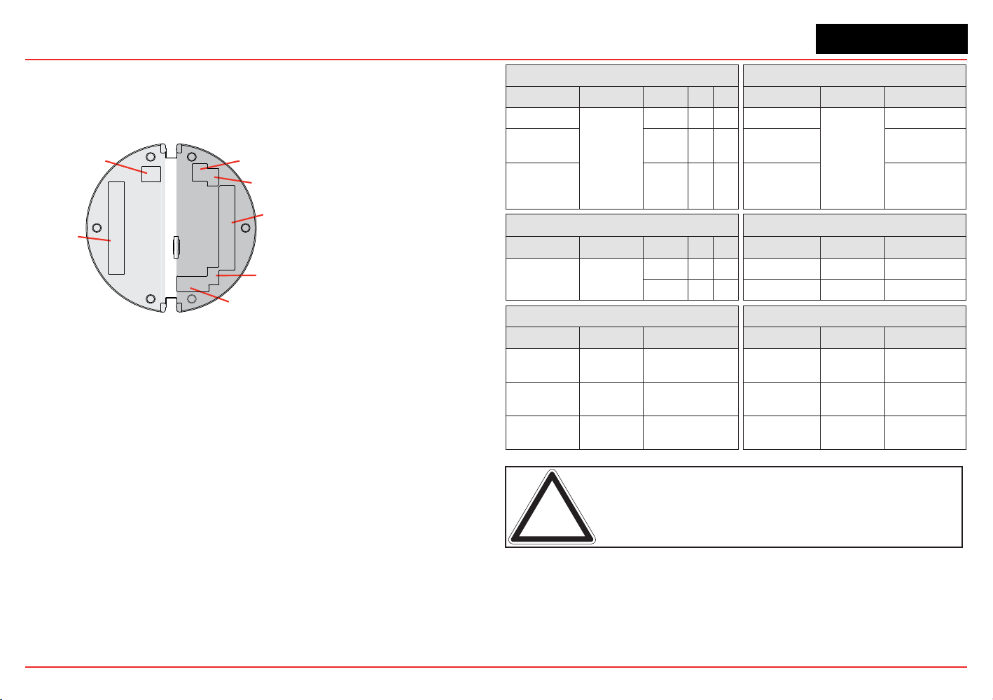
2.2.3 POD Connections
This illustration shows the connections available on each of the
terminal blocks for each type of personality board.
J1 - Remote HART
®
Connector Only
Personality
Boards
Option
Boards
A
B
C
D
E
F
Figure 35. XNX Personality Board Terminal Block Legend
Each of the personalities use a single terminal block for
connection with the exception of the IR personality, which
requires a second terminal block.
The personality boards also provide a dedicated pair of jumper
switchestodeneoutputofthetransmitterasisolated4-20mA,
Sink 20mA, or Source 20mA as well as a service jumper to allow
power to the loop to continue when the transmitter is being
serviced. A separate connector is used to activate local HART
(see Section 2.3.1).
Local HART provides an external access to control the
transmitter. An intrinsically safe (IS) barrier inside the transmitter
allows the user to attach an external hand-held interrogator
forprogrammingandconguration.Theexternalinterfaceis
intrinsically safe. It is installed in the transmitter’s lower left
cable/conduitport.
Table A Table B
Board Type Function S1 S2 Board Type Connection Function
EC Personality
4-20mA
Output
Source
EC Personality
TB1
Power, 4-20mA
mV
Personality
Sink
mV Personality
Power, 4-20mA,
Sensor
IR
Personality
Isolated
IR Personality
Power, 4-20mA,
IR Power and
Signal
Table C Table D
Board Type Function S3 S4 Board Type Connection Function
IR
Personality
IR 4-20mA
Input
Source
EC Personality J2 EC IS Barrier
Sink
IR Personality TB2 Com A and B
Table E Table F
Board Type Connection Function Board Type Connection Function
Relay TB4
Remote Reset
Connector
Relay TB3 Relay Output
Modbus SW5
Bus Loop
Terminators
Modbus TB3 Data Connection
Foundatin
Fieldbus
SW5 Simulation Mode
Foundation
Fieldbus
TB3 Data connection
Note: Open loop faults are not available due to HART, Modbus, and
Foundation Fieldbus interfaces where a 4-20 signal cannot be used.
In this case, open loop, 0mA must be used as the diagnostic.
The Option circuit boards vary depending upon the option
selected when ordered. Only one of the three available interface
options (relays, Modbus, or Foundation Fieldbus) can be
attached to the XNX transmitter. When installed, connections to
the options are made to connectors at the bottom of the POD.
XNX Universal Transmitter
Section 2 - Installation and Operation
37
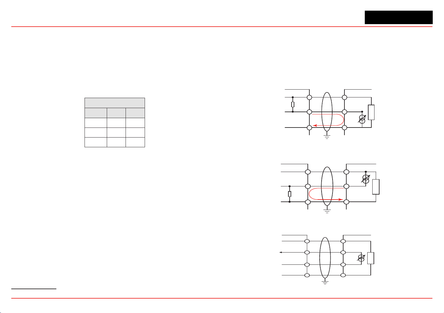
2.2.4
4-20mA Output, Common Connections, and
Power Settings
TheXNXUniversalTransmitterallowstheusertocongure
the 4-20mA output to Sink, Source, or Isolated mode
operation via two programming switches on the POD
1
. The
SwitchCongurationtableshowstheS1andS2settingand
correspondingoutputconguration.
Switch Conguration
Mode S1 S2
Source Down Up
Sink Up Down
Isolated Down Down
Mostcontrollersinthemarketwillacceptsource-congured
devices.Sink-conguredsignalsareusedinoldertechnology
controllers, which reduce the need for complete system
upgrades.In isolated-signal devices, if the controller fails or the
mAsignalwiresaredisconnectedorbroken,theelddevicewill
remain operational. Most controllers in the market will accept
isolatedcongureddevices.
Power and 4-20mA connections are made at TB-1 and are
identical for the EC, IR, and mV Personality Boards. For user
convenience, a second set of +Ve and -Ve power terminals have
been provided to eliminate the need for a secondary junction
box in multi-node systems when used with the supplied terminal
jumpers.
The total load resistance for the 4-20mA output should be
kept lower than 500Ω, including the resistance of the properly
selected 4-20mA cable and input impedance of the equipment
tobeconnnected.Theminimumloopimpedenceis200ohms;
1 The 4-20 mA output state is refreshed at least every two seconds (once per second is typical).
the maximum is 500 ohms. If the 20 mA output is not used, a 500
ohm resistor must be installed.
The XNX Universal Transmitter power consumption is dependent
onthesensorandoptionsforthespecicconguration.For
proper operation, the input voltage must be maintained at 16 to
32 VDC for EC and mV units and 18 to 32 VDC for IR units.
Controller
+VE
Signal
-VE
R
L
1
2
3
1-1
1-5
1-3
+V
+mA
-V
XNX
XNX Sink Configuration
Current
Flow
Figure 36. Sink wiring for XNX
XNX Source Configuration
Controller
+VE
Signal
-VE
R
L
1
2
3
1-1
1-6
1-3
+V
-mA
-V
XNX
Current
Flow
Terminate cable screen at the detector or controller, not both.
Figure 37. Source wiring for XNX
Controller
+V1
+V2
-V2
1-1
1-5
1-6
+V
+mA
-V
XNX
1-3
-mA
-V1
XNX Isolated Configuration
Figure 38. Isolated wiring for XNX
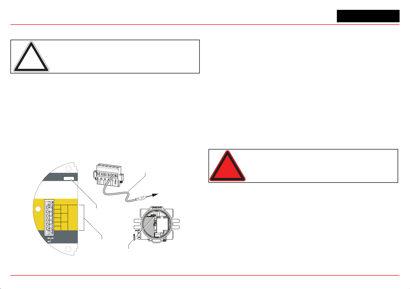
XNX Universal Transmitter
Section 2 - Installation and Operation
38
Labels applied to the back of the POD identify each of the
connection points.
Note: Pins 2 and 4 of terminal block TB1 have no internal connection
on the personality board. When used with the terminal block jumpers,
pins 2 and 4 can provide additional 4-20mA connections or supply
power for daisy-chained units.
2.2.5
Foundation Fieldbus Wiring
Foundation Fieldbus connections to the XNX transmitter are
made through a pluggable terminal block on the Foundation
Fieldbus option board, shown in Figure 39. A simulation switch
(SW5)isincludedontheboardtoenable/disablesimulation
mode. Terminals 3-1 through 3-4 are provided to facilitate bus
wiring;thereisnointernalconnectiontootherXNXcircuitry.
Terminal 3-1 is connected internally to 3-2. Similarly, terminal 3-3
is connected internally to 3-4.
+
+
TB-3 Modbus
Use shorting jumper
supplied to maintain
connection during
service
S5 Sim Mode
Out
In
3-1
3-2
3-3
3-4
3-5
3-6
F+
F+
F-
F-
FS
FS
TB-3 FFB
Jumper
assignments
1
2
3
4
5
6
to internal
ground lug
SW5 -
Sim switch
Internal ground lug
Foundation Fieldbus
ground cable
Figure 39. XNX Foundation Fieldbus option board and terminal block
2.2.6 Terminal Block Connections
Connections to the transmitter are made via pluggable terminal
blocks secured to the back of the POD. The terminal blocks are
keyedandpolarized.Acolorcodedlabelassistsinwiringwhen
the block is removed from the POD.
The terminals are suitable for use with 12 to 28 AWG or 0.8 to
2.5mm
2
wire.Wireinsulationmustbestripped5/16”(0.312”)or
8mm. Tighten each terminal to a maximum of 4.5 in-lbs (0.51 Nm).
Uptofourterminalblocksareprovided;eachhaving2,6,9,or10
positions (see the
XNX Quick Start Guide
for additional details).
Two terminal block jumpers are included to provide an electrical
connection without connection to the Personality Board. Install
the jumpers between pins 1 and 2 and between pins 3 and 4 to
support multi-node wiring.
Warning: When the transmitter is equipped with the optional Remote Mount
Kit, the remote sensor must be securely mounted in a fixed position. The Remote
Sensor kit is not intednded to be used as a hand-held sensor.
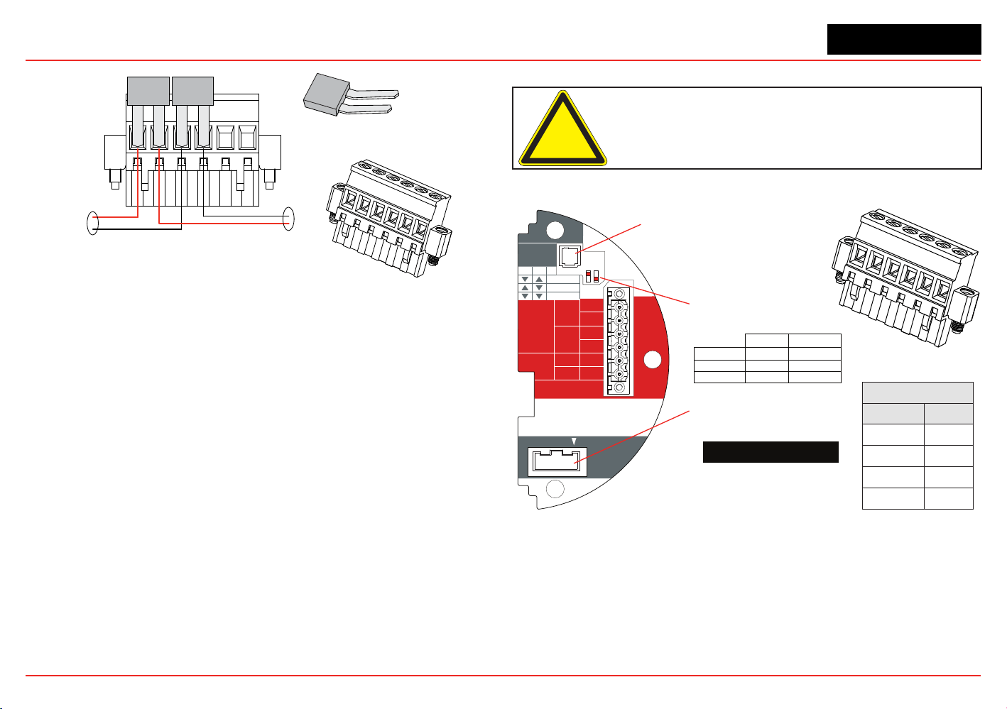
XNX Universal Transmitter
Section 2 - Installation and Operation
39
TB-1 Terminal Block
Terminal Block Jumper
IN
OUT
Figure 40. Pluggable Terminal Block and Terminal Block Jumper
2.2.7 EC Personality Wiring
Caution: Do not force the POD into the enclosure. Doing so may
result in damage to the wiring or the POD or may alter the switch
settings. If resistance is felt, wires may be preventing the POD from
being properly positioned.
TB1
Position EC
1
+24
2
3
0v
4
J1 - Local HART Connector
S1 and S2 - Signal Output
Jumper Switch
▼▼
▲
S2S1
Isolated
▼
Sink
▼
▲
Source
XNX EC TB-1
J2 - EC Barrier Connector
HART
20 mA
Operation
LOCAL
J1
S1
S1
Source
Sink
Isolated
S2
S2
EC Barrier
J2
+V 1-1
EC TB-1
4-20mA
HART
16-32 VDC
6.2W max.
1-2
-V 1-3
1-4
+mA 1-5
-mA 1-6
1
2
3
4
5
6
Figure 41. XNX EC Personality Board Terminal Blocks and Jumper Switches and Terminal
Block Assignments
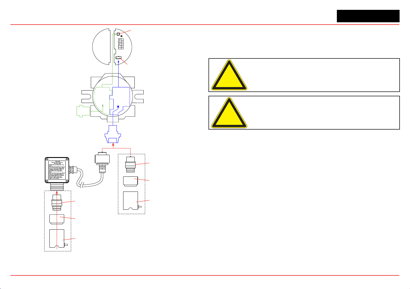
XNX Universal Transmitter
Section 2 - Installation and Operation
40
EC
Adaptor
Optional Local HART
IS Barrier must
be connected to J1
EC IS Barrier must
be connected to J2
4
3
2
1
-
+
6
5
J1 HART
S1 S2
J2 EC Barrier
Terminal Block 1
Local HART
IS Barrier
(optional)
HART
Adaptor
EC IS Barrier
Sensor Cartridge
Weatherproof Cap
Sensor Retainer
Sensor Cartridge
Weatherproof Cap
Sensor Retainer
Local Sensor Mounted to Transmitter
Sensor Mounted to
Remote Sensor Kit
Figure 42. EC Personality Wiring
XNX Electrochemical Sensor Installation
EC Sensor Installation
Caution: A missing oxygen cell will result in 0% V/V O
2
gas
concentration, thus triggering alarm events. In this situation, check
the connection of the EC cell to the sensor connector board.
Caution: For biased sensors (e.g., nitrogen dioxide) remove the
sensor stabilizer from the bottom of the sensor prior to installation.
Using Figure 42 as a guide, follow this procedure:
1. Verify that the label on the new sensor is the correct gas
type.
2. Unscrew the weatherproof cover, loosen the retainer
locking screw with the supplied hex key, and unscrew the
sensor retainer.
3. Plug in the new sensor. Take care to align the sensor pins
with the connector.
4. Retthesensorretainer,tightenthelockingscrewwiththe
hexkey,andrettheweatherproofcover.Countdowntime
of up to 180 seconds (depending on the sensor type) will
be displayed.
5. Acknowledgement of the gas type will be required before
proceeding. For more information on setting gas type, see
Section 2.5.1 Gas Selection.
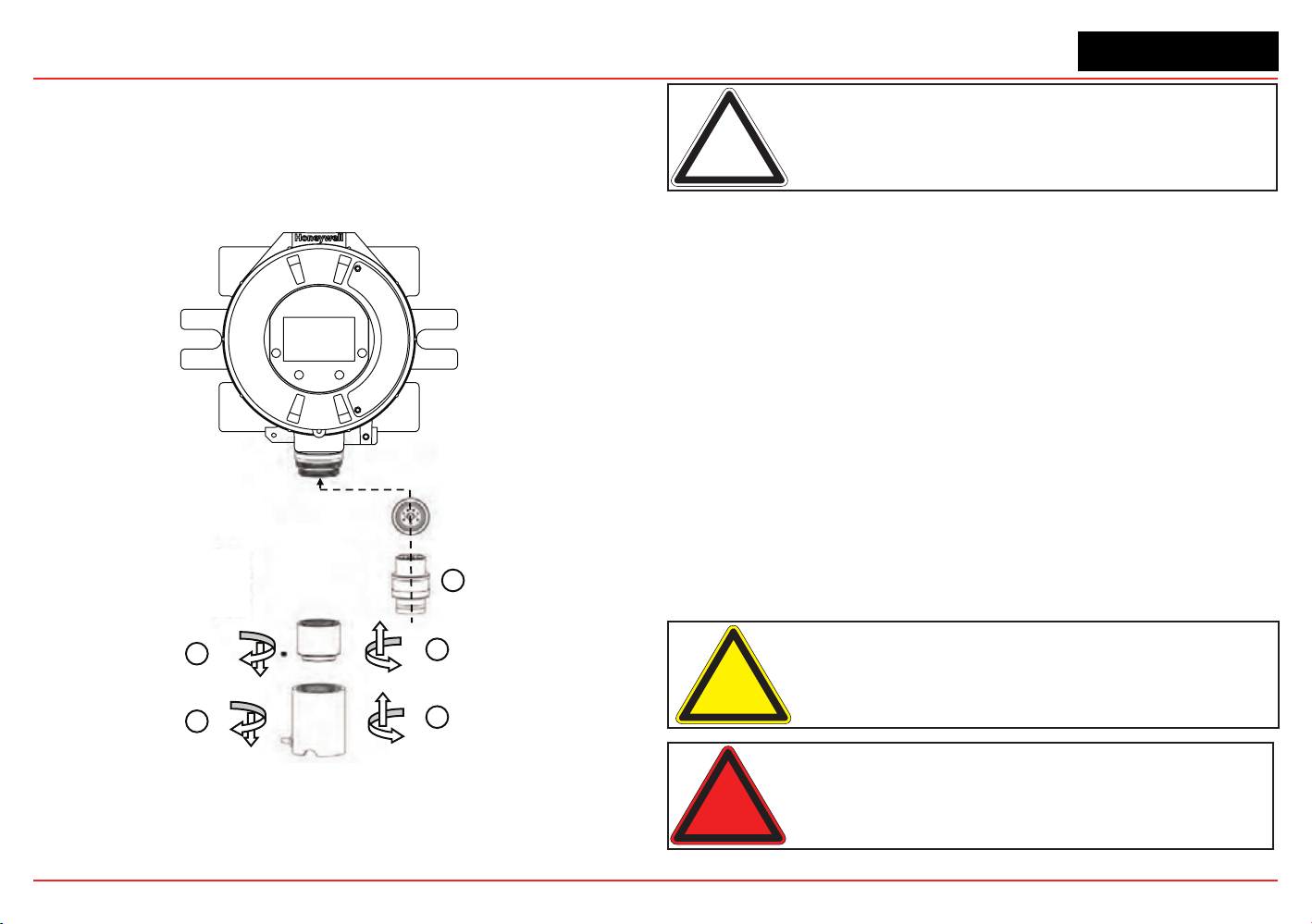
XNX Universal Transmitter
Section 2 - Installation and Operation
41
6. Afterthesensorisinstalledandthegastypeisconrmed,
the range, alarm levels, and other important settings must
beset;seeSection 2.5.
7. Afterthetransmitterhasbeencongured,calibrate
the sensor following the procedures in Section 3 -
Calibrations.
Transmitter
Sensor Retainer &
Locking Screw
2
1
3
4
5
New Sensor
Weatherproof Cap
Figure 43. Installing Plug In Sensor
Note: Reference Control Drawing 3000E3157 and 3000E3159 for
install requirements on EC cells and remote mounting.
XNX EC Sensor Remote Mounting Kit
The remote sensor mounting kit is used to mount the XNX EC
sensor up to 50 feet away from the transmitter. To mount the
sensor remotely, follow this procedure:
1. Unscrew the weatherproof cover, loosen the retainer
locking screw and unscrew the sensor retainer.
2. Remove the sensor by pulling without twisting.
3. Plug the remote sensor cable connector into the bottom of
the transmitter.
4. Route the cable to the location where the remote sensor is
to be mounted.
5. Optional: make a loop of cable at the junction box. This
will provide some slack for any future re-terminations.
6. If necessary, cut the cable to the required length.
Caution: Take care not to cut the cable too short. Once cut,
additional lengths of cable cannot be added as this would invalidate
the intrinsically safe certification.
Warning: Enclosures of remotely mounted sensors contain
aluminum. Be careful to avoid ignition hazards due to impact or
friction when installed in Zone 1 locations.
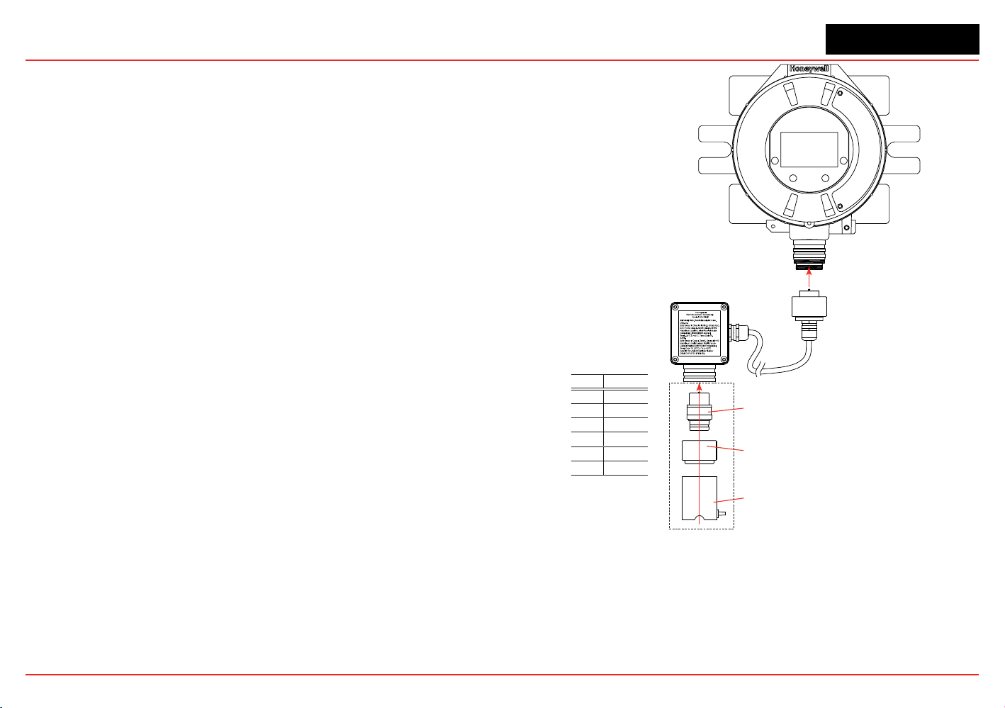
XNX Universal Transmitter
Section 2 - Installation and Operation
42
7. Mount the remote sensor junction box ensuring enough
roombelowtotthesensorandweatherproofcover.See
control drawing 3000E3157 in Section 7.2forspecic
mounting information.
8. Attach the cable to the remote terminal box via the gland
provided.
9. Make the wiring connections as shown in Figure 43.
10. Fit the Terminal box lid.
11. Plug the sensor into the socket at the bottom of the terminal
box.
12. Fitthesensorretainer,tightenthelockingscrew,andt
the weatherproof cover.
13. Calibrate the sensor following the procedure in Section
3.2.1.
Black
1 Yellow
Connections
Pin # Color
2 Green
3 Blue
4 White
5 Red
6
Sensor Cartridge
Weatherproof Cap
Sensor Retainer
Sensor Mounted to Remote Sensor Kit
Figure 44. Installing Remote Sensor Mounting Kit
XNX Universal Transmitter
Section 2 - Installation and Operation
43
2.2.8 mV Personality Wiring
XNX Universal Transmitter with the mV personality Board allows
interfacetoHA’sMultiPurposeDetector(MPD)andeldproven
705 and Sensepoint devices.
Caution: See Section 6 - Specifications to ensure that the
transmitter and the mV sensor have the appropriate approvals prior
to commissioning.
Caution: Verify that the mV sensor being installed has compatible
threads (3/4 NPT or M25).
Read Section 2.2whichdenestheXNXpowerand4-20mA
output connections that are common to all personalities.
Connections from the mV Sensor to the XNX are made via a
single pluggable terminal block allowing ease of installation and
service. Honeywell Analytics recommends that an 8” (203 mm)
service length for wiring be maintained. The wire colors for the
connections for each sensor type are shown in the following
Wire Color from Sensor table.
Verify that wires for 4-20mA outputs are routed away from
sources of noise such as relay wires.
Note: The black and red wires from the MPD are not used with the
XNX mV personality board. Ensure that they are properly isolated
from live connections. Do NOT cut the wires.
Caution: Do not force the POD into the enclosure. Doing so may
result in damage to the wiring or the POD or may alter the switch
settings. If resistance is felt, wires may be preventing the POD from
being properly positioned.
Caution: Be certain to dress the wires properly to ensure cabling
does not contact switches 1-2 on the back of the POD.
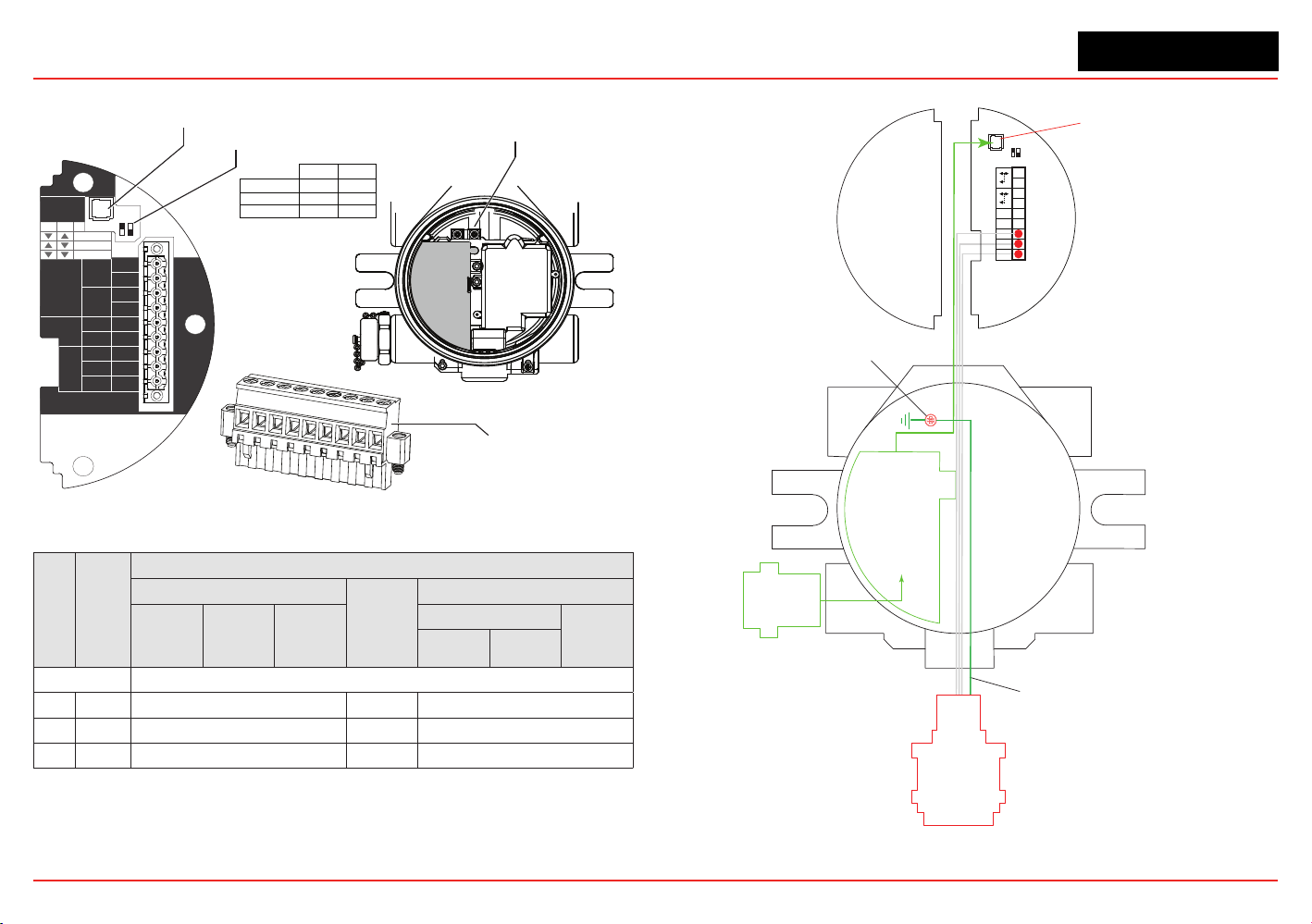
XNX Universal Transmitter
Section 2 - Installation and Operation
44
HART
20 mA
Operation
LOCAL
J1
S1
+V 1-1
mV TB-1
MPD, 705
Sensepoint
4-20mA
HART
16-32 VDC
6.5W max.
1-2
-V 1-3
1-4
+mA 1-5
-mA 1-6
Sense
1-7
0v 1-8
Ref 1-9
S1
Source
Sink
Isolated
S2
S2
J1 - Local HART Option Connector
1
2
3
4
5
6
7
8
9
internal
grounding lugs
S1 and S2 - 20mA Output
Jumper Switch
S2
S1
▼
▼
Isolated
▲
Sink
▼
Source
▼
▲
XNX mV TB-1
Figure 45. mV personality board terminal blocks and jumper switches.
TB-1 Desc.
Wire Color from Sensor
mV Catalytic Bead Sensor
Sensept
PPM*
mv MPD w/IR Sensor
MPD
705
705HT
Sensept
Senspt HT
IR 5%
IR Flam
CO
2
CH
4
Pins 1-6 See subsections in Section 2.2.4 for pin identification
7 Sense Brown Red Brown
8 0v White Green White
9 Ref Blue Blue Blue
*Internal earth ground; approximately one inch of the black sheath that contains the Sensepoint PPM’s four wires (red, blue,
green, silver) must be split to allow the silver grounding wire to reach the internal grounding lugs.
Local HART
IS Barrier
(optional)
HART
Adaptor
4
3
2
1
Ref
+
9
8
7
6
5
J1 HART
S1 S2
Terminal Block 1
Com
Sense
-
Optional Local HART
IS Barrier must
be connected to J1
Ground Wire from
Sensepoint PPM and HT
Internal Ground Lug
MPD
705
Sensepoint
Figure 46. mV Personality Wiring
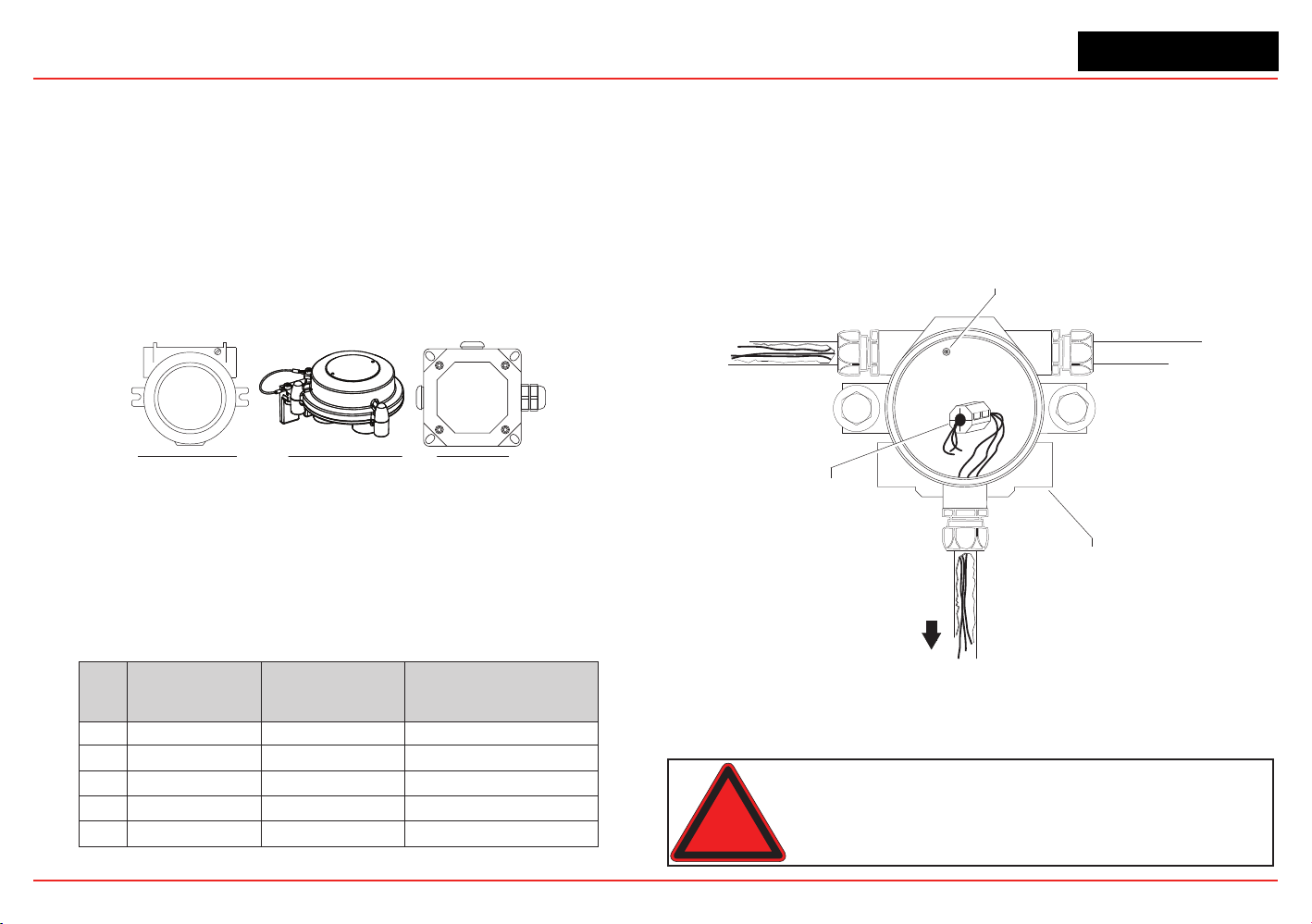
XNX Universal Transmitter
Section 2 - Installation and Operation
45
mV Remote Sensor Mounting
Thesensorcanbemountedremotelyfromthetransmitter;the
installation will vary by installed location, sensor and thread type
used. To remotely mount the sensor, follow this procedure:
1. Unscrew the transmitter’s weatherproof cover and loosen
the retainer locking screw with the supplied hex key.
2. Run conduit from one of the transmitter’s available conduit
ports to the location of the remote terminal housing.
A terminal housing provides a mounting base for the
sensor. The installation wiring enters the terminal housing
via conduit.
UL/CSA Aluminum Junction Box
2441-0022
UL/CSA Stainless Steel Junction Box
2110B2103
ATEX/IEC Junction Box
00780-A-0100
Figure 47. Remote Terminal Housings
The distance between the XNX Transmitter and remote
installation must comply with these parameters to insure proper
operation. Distances are dependent on sensor types and the
wire gauge used.
AWG Metric Wire Gauge
MPD CB1, 705 Series.
Sensepoint Series
Sensors
MPD IC1, IV1 & IF1 Sensors
24 0.25 mm
2
12m (47 ft.) 30m (97 ft.)
22 20m (65 ft.) 50m (162 ft.)
20 0.5 mm
2
30m (97 ft.) 80m (260 ft.)
18 50m (162 ft.) 120m (390 ft.)*
16 1.0 mm
2
80m (260 ft.)* 200m (650 ft.)*
* Frequency of Zero calibration may increase due to the changes in wire resistance from changing temperature.
3. Wire the pluggable terminal block as shown in Figure
45 then plug the connector into the back of the mV
personalityboard.InremotemountMPDcongurations,
the 3 wires connecting the pluggable terminal block and
the remote MPD must be routed through the supplied
ferrite bead (Honeywell Analytics part no. 0060-1051,
supplied in the accessory kit) as shown in Figure 48.
Internal Ground Lug
(do not use)
Power
Ferrite Bead
for Remote
Sensor Wiring
mV
Remote
Sensor
XNX Universal Transmitter
Figure 48. Ferrite bead wiring
4. Mounttheremotesensorjunctionboxwithsufcientroom
belowtotthesensorandweatherproofcover.
Warning: Install the junction box according to local codes and
manufacturer’s requirements.
XNX Universal Transmitter
Section 2 - Installation and Operation
46
5. Attach the conduit to the remote terminal box.
6. In the remote junction box, connect the wires from the
transmitter to the 3-way terminal block in the terminal box.
Note: The black and red wires from the MPD are not used with the
XNX mV personality board. Ensure that they are properly isolated
from live connections. Do NOT cut the wires.
Warning: The enclosures of remotely mounted 705HT sensors
contain aluminum. Be careful to avoid ignition hazards due to impact
or friction when installed in Zone 1 locations.
Allcableportdevicesandblankingelementsshallbecertiedin
typeofexplosionprotectionameproofenclosure“Exd”or“Exe”,
suitable for the conditions of use and correctly installed.
7. Attach and wire the sensor in the terminal box.
8. Fit the terminal box lid.
9. Fit the sensor.
10. Calibrate the sensor following the procedure in Section 3.2
- Calibration.
2.2.9 IR Personality Wiring
The XNX Universal Transmitter allows local programming and
congurationthroughthelocalLCDdisplayaswellasthrough
the HART protocol. Gas concentrations can be read at the
transmitter from Searchpoint Optima Plus or Searchline Excel,
via 4-20mA output as well as from the digital communication
connection on TB2 that can provide additional diagnostic
information. The gas concentration is taken from the digital
communication line as long as it is in agreement with the 4-20
mA output, otherwise the 4-20mA output takes precedence.
Caution: Dress the wires properly so that cabling does not contact
switches 1-4 on the back of the POD.
Thetransmitterprovidesa4-20mAoutputreectingtheinput
received. It also offers diagnostic information or data via HART
or any of the additional communication options offered.
Read Section 2.2
whichdenestheXNXpowerand4-20mA
output connections that are common to all personalities.
Warning: Power off the transmitter before changing S3 or S4. Both
switches must be set in either Source or Sink prior to applying power.
Caution: Do not force the POD into the enclosure. Doing so may
result in damage to the wiring or the POD or may alter the switch
settings. If resistance is felt, wires may be preventing the POD from
being properly positioned.
Do not adjust switch settings while power is applied to the
transmitter;doingsowillcausepermanentdamage.
Connecting a Searchpoint Optima Plus or Searchline Excel
Connections from the Searchpoint Optima Plus or Searchline
Excel to the transmitter are made via two pluggable terminal
blocks allowing ease of installation and service (see Figure
49). HA recommends that an 8” service length of wiring be
maintained.
Inremotemountcongurations,themaximumdistancebetween
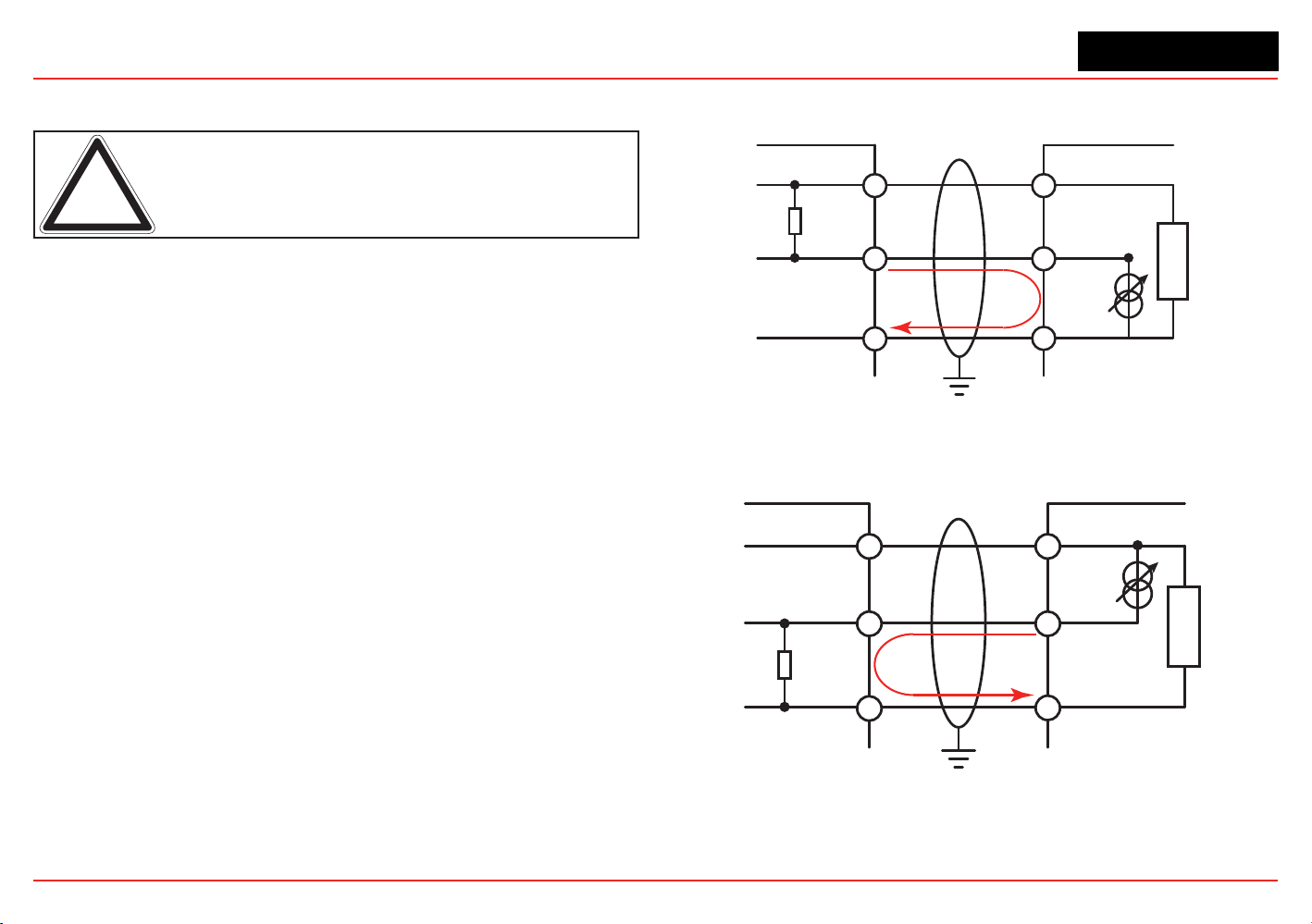
XNX Universal Transmitter
Section 2 - Installation and Operation
47
the XNX Transmitter and Optima Plus or Excel is 100 feet (33
meters) using 0.75 mm
2
(18 AWG) wire minimum.
Note: A second, black-handled screwdriver is included for use on
terminal blocks 2 and 4. This tool is smaller than the magnetic wand
and is designed to fit into the terminal connections on TB2 and TB4.
The Searchpoint Optima Plus or Searchline Excel can be
supplied in either Sink or Source mode operation and is typically
labeled on the white wire exiting the Searchpoint Optima Plus or
Searchline Excel. Use the table in Figure 50 to set S3 and S4 to
the same output type that appears on the wire tag of the IR
device.
For more information see the Searchpoint Optima Plus Operating
Instructions (2104M0508) or the Searchline Excel Technical
Manual (2104M0506).
Connecting Generic mA Devices
Use the following schematics to set switches S3 and S4 They
must
be set to the same output type (which appears on the wire
tag of the mA device).
The IR personality type provides for a generic mA input under
sensortypeconguration.Thetransmittercanbeusedto
convert the mA input to be read over HART or optional Modbus
or Foundation Fieldbus protocols and set optional relays (if
equipped).AdditionalcongurationofgastypeandunitID
for reporting is required (see Gas Selection). For Generic mA
devices, input values below 3mA will generate Fault 155.
XNX
+IR
Signal
-IR
R
L
1-7
1-9
1-8
+V
+mA
-V
mA Device
Current
Flow
24V 7W Max
XNX S3 and S4 must be in the UP position
Set mA Device and XNX to the same output type.
Figure 49. XNX mA input sink conguration
XNX
+IR
Signal
-IR
R
L
1-7
1-9
1-8
+V
-mA
-V
mA Device
Current
Flow
XNX S3 and S4 must be in the DOWN position
Set mA Device and XNX to the same output type.
Figure 50. XNX mA input source conguration
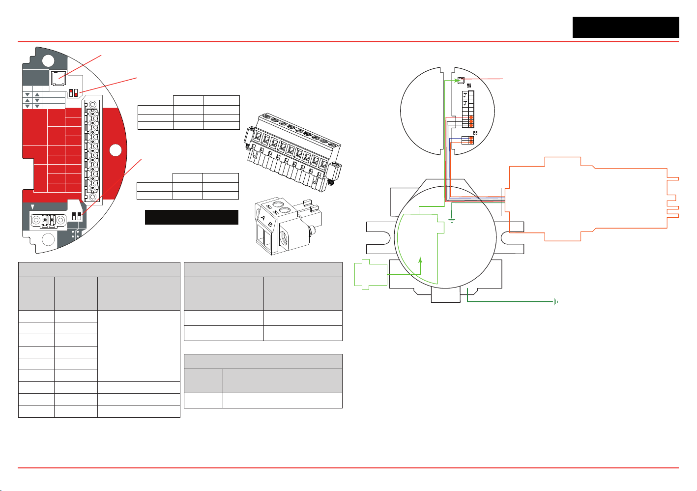
XNX Universal Transmitter
Section 2 - Installation and Operation
48
Note:
Honeywell Aanalytics recommends that Excel or Optima and the XNX transmitter be wired to building
ground. The system should be grounded at only one point.
HART
20 mA
Operation
LOCAL
J1
S1
+V 1-1
Searchline
Searchpoint
4-20mA
HART
18-32 VDC
13.2W max.
1-2
-V 1-3
1-4
+mA 1-5
-mA 1-6
1-7
- Ir
+ Ir
1-8
Sig 1-9
S1
Source
Sink
Isolated
S2
S2
Ir TB-1
TB-2 Ir Data
S3
Source
Sink
S4
▼▼
▲▼
▼▲
S2S1
Isolated
Sink
Source
J1 - Local HART Connector
S1 and S2 - 20mA Output
Jumper Switch
S3 and S4 - IR 20mA Input
Jumper Switch
XNX IR TB-1
▼
▲
▼
▲
S4S3
Sink
Source
TB2
Terminal No.
From Searchpoint
Optima Plus
Searchline Excel
A Blue
B Orange
TB1
Terminal
No.
Desc.
From Searchpoint
Optima Plus
Searchline Excel
1 +24v
See Section 2.2.4
Common Connections
.
2
3 0 VDC
4
5 +20mA
6 -20mA
7 +24VDC Red
8 0VDC Black
9 Sig - 20mA White
XNX
Desc.
From Searchpoint Optima Plus
Searchline Excel
Earth Green/Yellow
1
2
3
4
5
6
7
8
9
TB1
TB2
Figure 51. XNX IR
Personality Board Terminal
Blocks, Jumper Switches
and Wiring Guide
Local HART
IS Barrier
(optional)
HART
Adaptor
Optional Local HART
IS Barrier must be
connected to J1
Searchpoint
Optima Plus
4
3
2
1
Sig
Gnd
+24
+
9
8
7
6
5
J1 HART
S1 S2
Terminal Block 1
B
A
2
1
Terminal Block 2
IR Data
S3 S4
To Building
Ground
To Building
Ground
Figure 52. IR Personality Wiring - Searchpoint Optima Plus
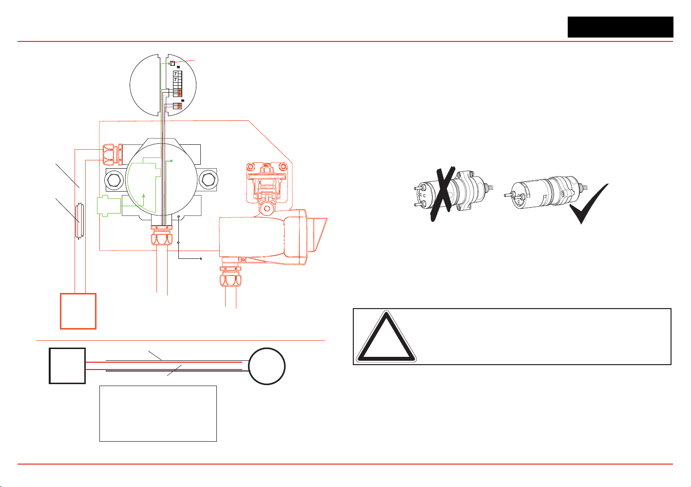
XNX Universal Transmitter
Section 2 - Installation and Operation
49
Local HART
IS Barrier
(optional)
Optional Local HART
IS Barrier must be
connected to J1
4
3
2
1
Sig
Gnd
+24
+
9
7
6
5
J1 HART
S1 S2
Terminal Block 1
B
A
1
2
Terminal Block 2
IR Data
S3 S4
8
HART
Adaptor
Searchline Excel
Internal
body screw
To local
building
ground
External
body screw
Mounting plate
must be connected to
the same earth ground
as the XNX transmitter
Isolation kit is not
important in this
configuration
Control
Room
Conduit/armored cable
Earth loop through the
conduit/armored cable
must be avoided
RFI and EMC shield
Control
Room
XNX
Transmitter
Armor
RFI and EMC shield
Notes:
Ground loops through the armor must be avoided.
If armor is connected to the XNX transmitter via a conductive
EXd cable gland, the armor must not be earthed at any other
location (this will prevent ground loops). Since it is already earthed
at the transmitter. Armor must be grounded only if an isolating gland
is used to connect it to the transmitter.
Ground loops through the RFI and EMC shield must be avoided.
RFI and EMC shield must be connected to a clean/instrumentation
earth ground at the control room. To avoid an earth loop, connect it
only at the control room (not at the transmitter).
Figure 53. IR Personality Wiring - Searchline Excel
Attaching the Searchpoint Optima Plus to the XNX Universal
Transmitter
ForM25entries,inserttheseal(P/N1226-0410)intotheproper
cable/conduitopeningthenthreadthelocknut(P/N1226-0409)
onto the Optima to the end of the threads. Thread the Optima
bodyintothetransmitteruntilthesealcompressesand/orthe
Optima bottoms out. Reverse until the semi-circular pattern of
holes on the front of the weather protection are on the bottom
(see below). Tighten the locknut to the XNX body.
Figure 54. Searchpoint Optima Plus orientation
The3/4”NPTportsdonotrequirethesealandlocknut.Theform
of the threads provide positive locking and sealing.
Note: When attaching the Searchpoint Optima Plus, coat the threads
with an anti-seize compound to prevent corrosion.
Searchline Excel and Searchpoint Optima Plus Remote Installation
Junction Boxes are available for the Searchline Excel and
Searchpoint Optima Plus to facilitate remote mounting from
the XNX Universal Transmitter. Junction boxes are available
forinstallationsrequiringUL/CSAorATEXapprovals.Consult
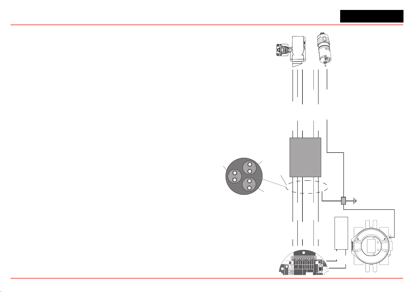
XNX Universal Transmitter
Section 2 - Installation and Operation
50
the Searchline Excel Technical Handbook (2104M0506) or
Searchpoint Optima Plus Operating Instructions (2104M0508)
forspecicsonremoteinstallationsorcontactyourHoneywell
Analytics representative for more information.
Searchpoint Optima Plus or Searchline Excel Wiring Recommendations
When wiring the XNX transmitter and the Searchpoint Optima
Plus or Searchline Excel for remote applications, the general
recommendationsoftheANSI/TIA/EIA-485-Astandardmustbe
adhered to with the following additions:
1. When mounting the Searchline Excel or Searchpoint
Optima Plus, run wiring connections between each Excel
or Optima and the transmitter in a dedicated separate
conduit.
2. Use 18 AWG twisted shielded cable for the RS485
connection between Excel or Optima and the XNX. Make
sure that the shield of the cable is grounded to earth and
XNX ground on one end ONLY.
3. Avoid running wiring near main cables or other high
voltage equipment.
4. Do
not
apply 120 ohm terminating resistors. These
resistors are not required due to low data rates.
5. Honeywell Analytics recommends that Excel or Optima
sensors and the XNX transmitter be wired to building
ground. The system should be grounded at one point only.
INSTALLATION TIP:
Always perform a soft reset after connecting the Searchpoint
OptimaandXNXtransmitterforthersttime.Thesoftresetis
performed by accessing the transmitter’s Calibration Menu.
HART
20 mA
Operation
LOCAL
J1
S1
+V 1-1
Searchline
Searchpoint
4-20mA
HART
18-32 VDC
13.2W max.
1-2
-V 1-3
1-4
+mA 1-5
-mA 1-6
1-7
- Ir
+ Ir
1-8
Sig 1-9
S1
Source
Sink
Isolated
S2
S2
Ir TB-1
TB-2 Ir Data
S3
Source
Sink
S4
IR Sens (silver)
IR +ve (red)
IR -ve (black)
RS485+ (yellow)
RS485- (blue)
IR Sens
IR +ve
IR -ve
RS485+
RS485-
Twisted Shielded Pair
18 AWG
Single Ground Point
RS485 Cable Shield
Ground ONE END ONLY
Power Supply
+ve
-ve
Junction Box
Searchline Excel
Searchpoint Optima Plus
Pair 1: Unit Ground and IR Sense
(Cable Shield Grounded ONE END ONLY)
Pair 2: RS485+ and RS485-
(Cable Shield Grounded ONE END ONLY)
Pair 3: IR +ve and IR -ve
(Cable Shield Grounded ONE END ONLY)
Unit Gnd (green)
Figure 55. XNX IR Remote
Wiring
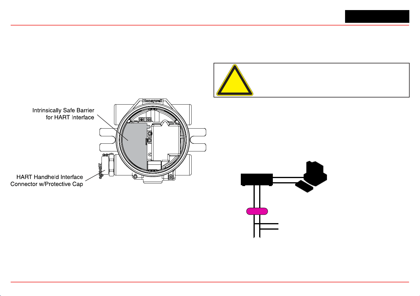
XNX Universal Transmitter
Section 2 - Installation and Operation
51
2.3 Options
2.3.1 Local HART Interface
Available with any sensor technology or option, this option
provides an external access to the HART interface in the
transmitter. An IS barrier inside the transmitter allows the user to
attach an external hand-held interrogator for programming and
conguration.Theexternalinterfaceisinstalledinthelowerleft
cable/conduitportofthetransmitterandisintrinsicallysafe(IS).
Figure 56. XNX Universal Transmitter with HART Interface IS Barrier installed
The HART protocol is a communication technology used with
smart process instrumentation, providing two-way digital
communication simultaneously with the 4-20mA analog signaling
used by traditional instrumentation equipment. For more
detailed information on HART, see the HART Protocol and www.
hartcomm.org.
Implementation of the HART protocol in the XNX transmitter:
•
MeetsHART6.0physicallayerspecication
• The physical layer is tested according to HART Physical
Layer Test Procedure, HCF_TEST-2.
• Data transfer rate: 1200 bps.
HART devices can operate in point-to-point or multidrop
congurations.
Caution: Device address changes must be performed only by
qualified service personnel.
Point-to-Point Mode
In point-to-point mode, the 4–20 mA signal is used to
communicate one process variable, while additional process
variables,congurationparameters,andotherdevicedataare
transferred digitally via HART protocol (Figure 57). The 4–20 mA
analog signal is not affected by the HART signal.
Control System
or Other Host Application
Multiplexer
Barrier
Handheld Terminal
Field Device
Note: Instrument power is provided by an interface
or external power source that is not shown.
Figure 57. Point-to-Point Mode of Operation
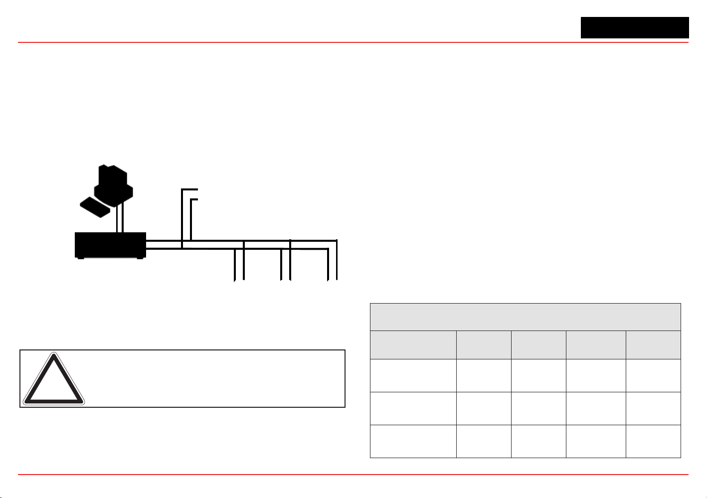
XNX Universal Transmitter
Section 2 - Installation and Operation
52
Multidrop Mode
The multidrop mode of operation requires only a single pair of
wires and, if applicable, safety barriers and an auxiliary power
supplyforupto8elddevices(Figure 58). All process values are
transmitteddigitally.Inmultidropmode,allelddevicepolling
addressesare>0,andthecurrentthrougheachdeviceisxedat
a minimum value (typically 4 mA).
Input/Output (I/O) System
Handheld Terminal
Field Devices
Control System or
Other Host Application
Note: Instrument power is provided by an interface
or external power source that is not shown.
Figure 58. Multidrop Mode of Operation
Note: Use multidrop connection for supervisory control installations
that are widely spaced, such as pipelines, custody transfer stations,
and tank farms.
In general, the installation practice for HART devices is the same
as conventional 4-20mA instrumentation. Individually shielded
twisted pair cable, either in single-pair or multi-pair varieties, is
the recommended wiring practice. Unshielded cables may be
used for short distances if ambient noise and cross-talk will not
affect communication.
Theminimumconductorsizeis0.51mmdiameter(#24AWG)for
cable runs of less than 5,000 ft (1,524m) and 0.81mm diameter
(#20AWG)forlongerdistances.
Cable Length
Most installations are well within the 10,000 ft (3,000 m)
theoretical limit for HART communication. However, the electrical
characteristics of the cable (mostly capacitance) and the
combination of connected devices can affect the maximum
allowable cable length of a HART network. The table below
shows the effect of cable capacitance and the number of
network devices on cable length. The table is based on typical
installations of HART devices in non-IS environments, i.e. no
miscellaneous series impedance.
Detailed information for determining the maximum cable length
foranyHARTnetworkcongurationcanbefoundintheHART
PhysicalLayerSpecications.
Cable Capacitance – pf/ft (pf/m)
Allowable Cable Lengths for 1 mm (18 AWG) Shielded Twisted Pair – feet (meters)
Number of Network
Devices
20 pf/ft
(65 pf/m)
30 pf/ft
(95 pf/m)
50 pf/ft
(160 pf/m)
70 pf/ft
(225 pf/m)
1
9,000 ft
(2,769 m)
6,500 ft
(2,000 m)
4,200 ft
(1,292 m)
3,200 ft
(985 m)
5
8,000 ft
(2,462 m)
5,900 ft
(1,815 m)
3,700 ft
(1,138 m)
2,900 ft
(892 m)
8
7,000 ft
(2,154 m)
5,200 ft
(1,600 m)
3,300 ft
(1,015 m)
2,500 ft
769 m)
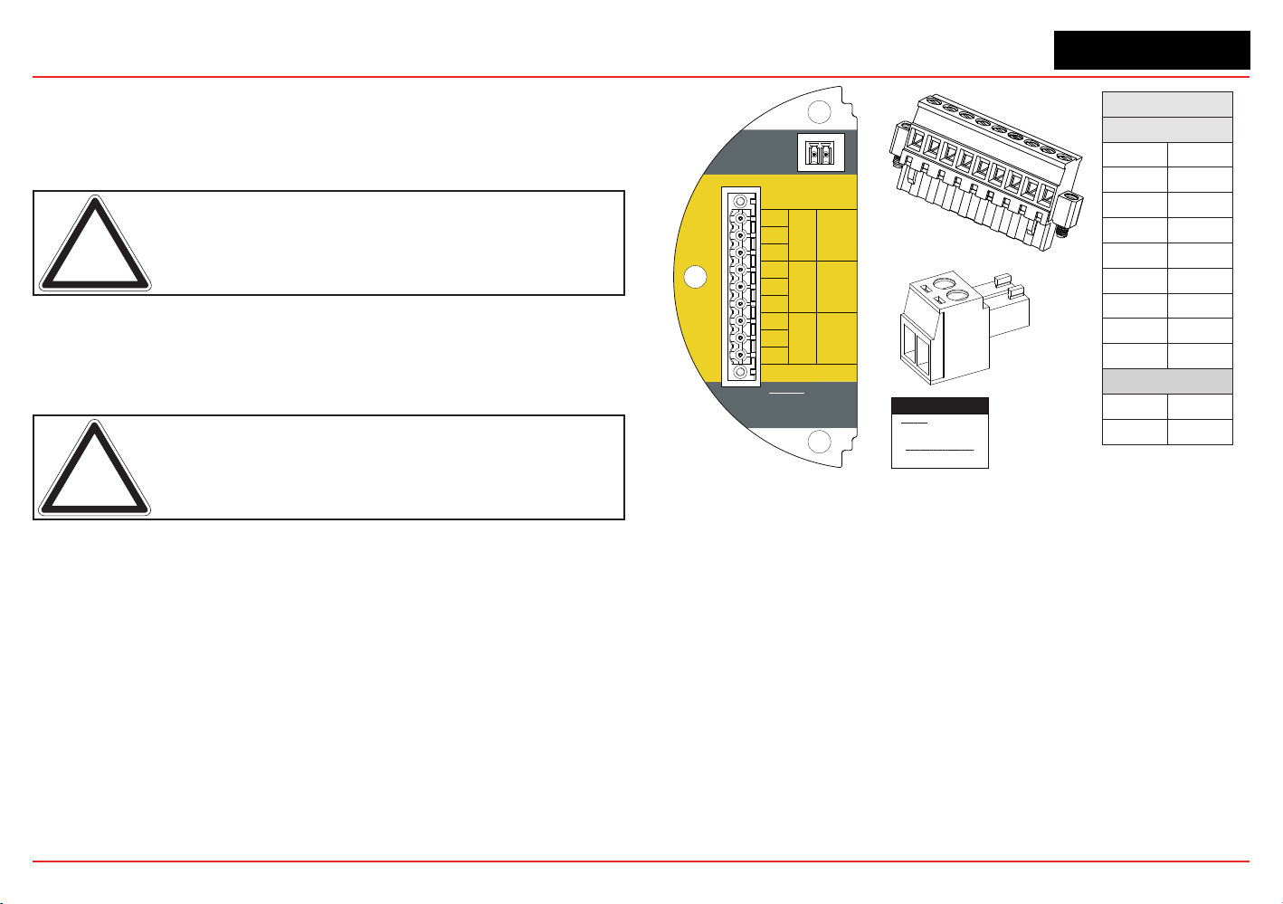
XNX Universal Transmitter
Section 2 - Installation and Operation
53
2.3.2 Relays
The relay option (XNX-Relay) provides 3 form “C” SPCO contacts
for alarm and fault indication. TB4 allows alarms to be reset
remotely.
Note: This option is not available when the Modbus or Foundation
Fieldbus options are installed.
Wiringfortherelaysisthroughanavailablecable/conduitportto
a pluggable terminal block. See Figure 35 for the terminal block
legend.
Note: A second, black-handled screwdriver is included for use on
terminal blocks 2 and 4. This tool is smaller than the magnetic wand
and is designed to fit into the terminal connections on TB4.
The XNX transmitter has three relays: relay 1 is for alarm level
1, relay 2 is for alarm level 2, and relay 3 is for faults and special
states. All special states are indicated by the fault relay.
Honeywell Analytics recommends that the fault relay be used in all
installations to maintain safe operation. See Set Alarm Values for
more information.
The relay state is refreshed every 2 seconds. The fault relay is
normallyenergizedindicatingproperoperation.Intheeventof
power failure or fault, the C-NO connection will open.
Warning: Power
externally supplied.
Disconnect at source
prior to servicing.
3-5
3-4
3-3
3-2
3-1
3-6
3-7
3-8
3-9
C
NC
TB4
Remote
Reset SW
Relay Ratings
250VAC 5A
24VDC 5A
NO
C
NC
NO
NC
C
NO
Fault Level 2 Level 1
TB-3 RELAY
TB3 Relay Connections
Warning: Power externally
supplied, disconnect at source
prior to servicing
Relay Contact Ratings:
250 VAC 5 amps
24 VDC 5 amps
Relay
TB3
1
NC
2
C
3
NO
4
NC
5
C
6
NO
7
NC
8
C
9
NO
TB4
1
1
2
2
1
2
3
4
5
6
7
8
9
TB3
1
2
TB4
Figure 59. XNX Relay Option Board Terminal Blocks
2.3.3 Modbus
The optional Modbus interface allows all transmitter local
user interface (LUI) functions and parameter settings to be
transmitted.
Modbus is a master-slaves protocol. Only one master (at a
time) is connected to the bus. Up to 247 slave nodes are also
connected to the same serial bus. Modbus communication is
always initiated by the master. The slave nodes never transmit
data without receiving a request from the master node. The slave
nodes never communicate with each other. The master node
initiates only one Modbus transaction at a time.
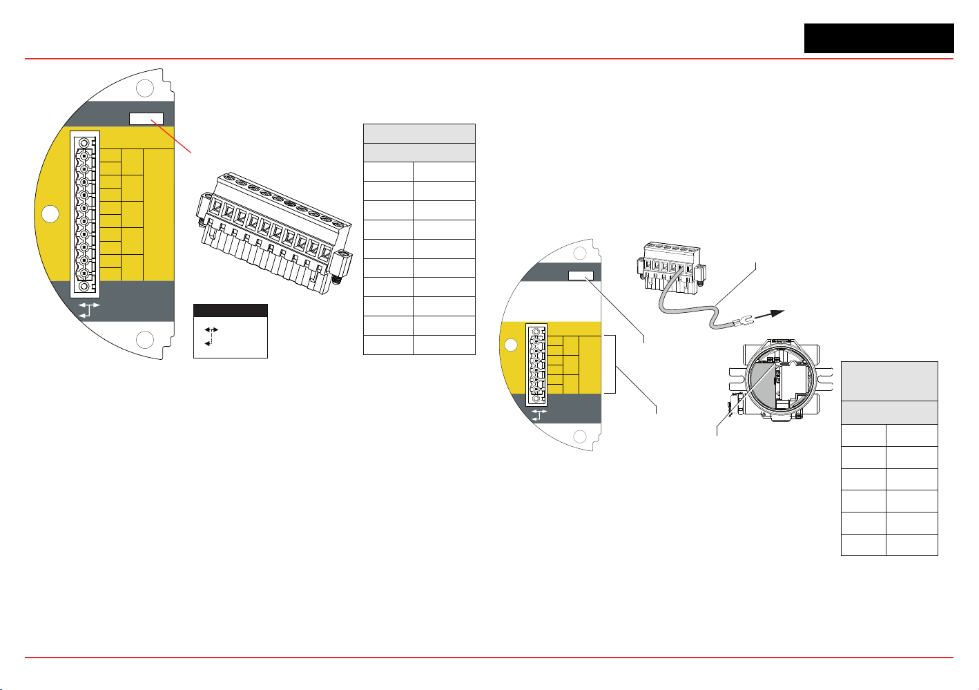
XNX Universal Transmitter
Section 2 - Installation and Operation
54
Terminals 3-1 through 3-4 are provided to facilitate
bus wiring; there is no internal connection to other XNX
circuitry. Terminal 3-1 is connected internally to 3-2.
Similarly, terminal 3-3 is connected to 3-4
3-5
3-4
3-3
3-2
3-1
3-6
3-7
3-8
3-9
3-10
A
-
-
+
+
A
B
B
S
TB-3 Modbus
S
Use shorting jumper
supplied to maintain
connection during
service
S5 EOL Term
Out
In
R
T
=120
TB3 Modbus Connections
Use Jumper
to maintain
connection
during service
SW5 - Loop Termination
Modbus
TB3
1
+
2
+
3
-
4
-
5
A
6
A
7
B
8
B
9
S
10
S
1
2
3
4
5
6
7
8
9
10
Figure 60. XNX Modbus Option Board Terminal Block / Jumper Switch
Modbus connections to the XNX are made through a pluggable
terminal block on the Modbus interface circuit board. Modbus
RTUprotocolusesASCII/Hexprotocolsforcommunication.See
Figure 35 for the terminal block legend. A loop termination point
(SW5) is included on the Modbus interface board to provide
termination of the Modbus loop.
2.3.4 Foundation Fieldbus
Foundation Fieldbus connections to the XNX transmitter are
made through a pluggable terminal block on the Foundation
Fieldbus option board, shown in Figure 60. A simulation switch
(SW5)isincludedontheboardtoenable/disablesimulation
mode. Terminals 3-1 through 3-4 are provided to facilitate bus
wiring;thereisnointernalconnectiontootherXNXcircuitry.
Terminal 3-1 is connected internally to 3-2. Similarly, terminal 3-3
is connected internally to 3-4.
+
+
TB-3 Modbus
Use shorting jumper
supplied to maintain
connection during
service
S5 Sim Mode
Out
In
3-1
3-2
3-3
3-4
3-5
3-6
F+
F+
F-
F-
FS
FS
TB-3 FFB
Jumper
assignments
1
2
3
4
5
6
to internal
ground lug
SW5 -
Sim switch
Internal ground lug
Foundation Fieldbus
ground cable
Foundation
Fieldbus
TB3
1
F+
2
F+
3
F-
4
F-
5
FS
6
FS
Figure 61. Foundation Fieldbus Option Board, Terminal Block, Jumper Switch
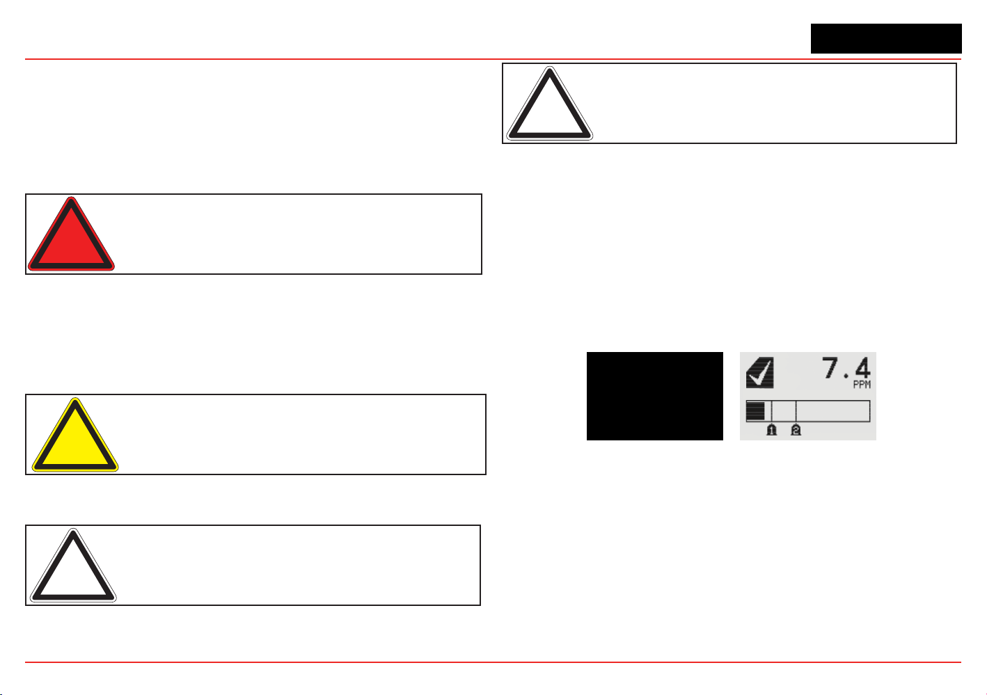
XNX Universal Transmitter
Section 2 - Installation and Operation
55
2.4 Powering the XNX for the First Time
2.4.1 XNX Units Congured for EC, mV, and IR
(except Searchline Excel)
Aftermounting,wiringthetransmitter,wiringthespecicmVorIR
sensor or installing the EC cartridge, the installation is visually and
electrically tested as described below.
Warning: Minimum and maximum controller alarm levels should not
be set at less than 10% or greater than 90% of the full scale range
of the sensor. CSA and FM agency limits are 60% LEL or 0.6mg/m
3
.
1. Verify that the transmitter is wired correctly according to
this manual and the associated control equipment manual.
2. If equipped, unscrew the weatherproof cover, loosen the
sensor retainer locking screw, and unscrew the retainer.
3. For EC sensors, plug in the sensor cartridge, taking care to
align the sensor pins with the connector holes in the PCB.
Caution: For toxic sensors, remove the shorting clip from the bottom
of the sensor prior to installation. No shorting clip is provided with O
2
sensors.
4. Retthesensorretainer,tightenthelockingscrewandret
the weatherproof cover.
Note: Before replacing the cover on the transmitter housing, coat the
threads with anti-seize compound to prevent corrosion buildup.
Note: Inspect the cover O-ring for cracking or any other defects that
might compromise the integrity of the seal. If it is damaged, replace
with the O-ring supplied in the accessory kit.
5. Apply power to the transmitter. This will in turn provide
power to the sensor.
6. During warmup, the XNX transmitter will be forced to 2mA
(inhibit mode).
7. The transmitter will enter a boot-up routine displaying the
initializationscreen.Thetransmitterloadsitsoperating
system, data from the sensor, sensor software version
numbers, gas type, the detection range and span
calibration gas level, estimated time to next calibration
due, and self test result. This will take about 45 seconds.
Figure 62. XNX Initialization and General Status Screens
Inthenalstagesofboot-up,warningsandfaults
may be observed until the user performs the proper
conguration,calibration,andresetactivities
described in the following sections. See Section 5 for
descriptions of warnings and faults.
Once the General Status screen appears, the
transmitter and sensor are in normal monitoring mode.
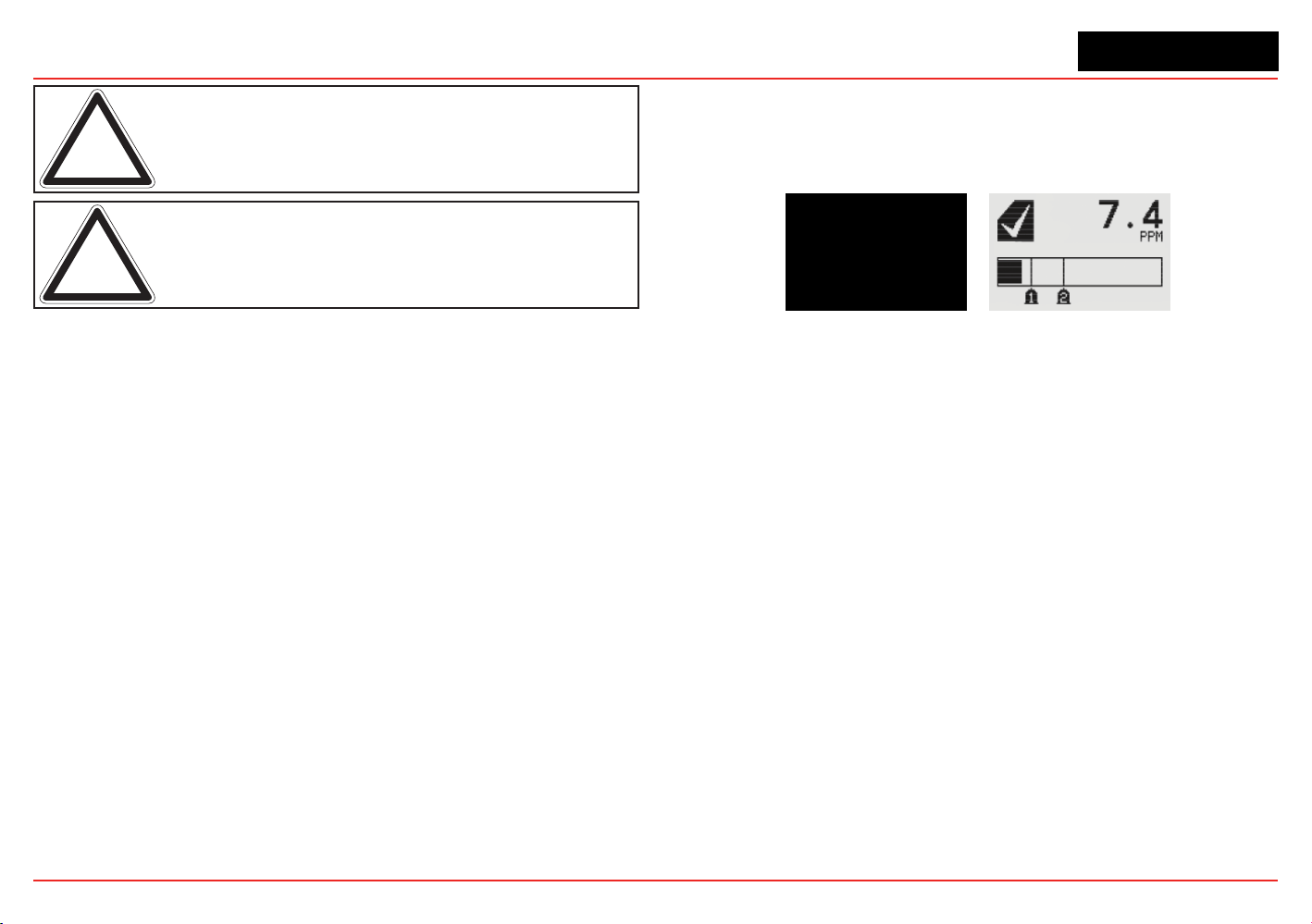
XNX Universal Transmitter
Section 2 - Installation and Operation
56
Note: Calibration of sensors attached to the transmitter is mandatory
before the sensor can be used for gas monitoring. Refer to Section
3 - Calibration for the procedure.
Note: For initial commissioning, refer to EN 60079-29-2.
2.4.2 LCD and LED Test
TheLCDandLEDtestisperformedintheinitializationafter
powering on. All LCD pixels and LEDs (red, green, and yellow)
are turned on for 1.5 seconds. The LCD then goes blank and the
LEDs turn off.
2.4.3 XNX IR Units Congured for Searchline Excel
WhenpoweringthetransmitterttedwithaSearchlineExcel
sensor, the following procedure must be followed to assure
proper installation.
1. Verify that the transmitter is wired correctly according to
this manual and the associated control equipment manual.
2. Apply power to the XNX transmitter. This will in turn
provide power to the sensor.
3. Thesensoroutputwillbeforcedto2mA(defaultfault/
inhibit).
4. The XNX transmitter will enter a boot-up routine, displaying
theinitializationscreen.Thetransmitterwillloadits
operating system, data from the sensor, sensor software
version numbers, gas type, the detection range and span
calibration gas level, estimated time to next calibration
due, and self test result. This will take about 45 seconds.
Figure 63. XNX Initialization and General Status Screens
Inthenalstagesofboot-up,warningsandfaults
may be observed until the user performs the proper
conguration,calibration,andresetactivities
described in the following sections. See Section 5 for
descriptions of warnings and faults.
5. When the XNX completes boot-up, perform a soft reset
(see Section 3.6 Soft Reset) on the Excel sensor from the
Calibration Menu. When the soft reset is intitated, the RS-
485 communication will be temporarily interrupted and
faultsF120and/orF161maybeobserved.TheRS-485
communication will be re-established in a few minutes and
the faults will automatically be reset in the Non-Latching
mode.F120and/orF161mustberesetmanuallyinthe
Latching mode.
6. Set the Path Length for the application, then align the
transmitter and receiver (see Section 3.5 Align Excel).
7. Once the alignment is complete, a Zero Calibration
must be performed on the Excel sensor to complete
the commissioning process. (See the Searchline Excel
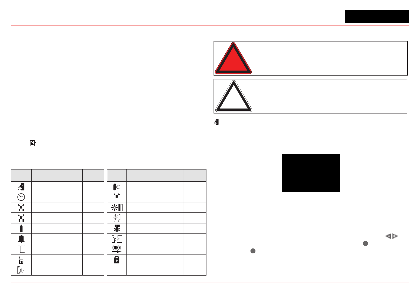
XNX Universal Transmitter
Section 2 - Installation and Operation
57
TechnicalManualforcalibrationinformationP/N
2104M0506).
8. Reset any faults that appear in the transmitter’s display.
The XNX transmitter and Searchline Excel sensor are now
ready to monitor.
2.5 Conguring the XNX Universal
Transmitter
The XNX Universal Transmittercanbeconguredviathefront
panelbyusingthemenusavailableinCongureMenu.For
information on accessing and navigating the menus, see Section
1.4.1.
2.5.1 Congure Menu
FunctionsintheCongureMenuandthesecuritylevelsrequired
to change them are explained in this table.
Symbol Description
Security
Level
Symbol Description
Security
Level
Select Language 1 Calibration Interval 2
Set Date & Time 1
✓
Accept New Sensor
Type
2
Set mV Sensor Type 2 Beam Block Options 2
Set mA Sensor Type 2 Path Length 2
Gas Selection 2 Unit ID 2
Range & Alarms 2 Relay Options 2
Latching/Non-
latching
2 Fieldbus Options 2
Set Units 2 CongureSecurity 2
mA Levels 2
Warning: When configuring or communicating with the transmitter
using the front panel displays, resume monitoring by exiting all
menus and returning to the General Status menu manually. No time
outs are invoked.
Note: With the exception of Inhbit Mode, gas measurement
continues in the background allowing users to navigate screens
without taking the transmitter offline.
Select Language
Available languages for the XNX transmitter are English, Italian,
French, German, Spanish, Russian, Mandarin, and Portuguese.
Figure 64. Select Language Menu
Different screens are used to display each of the eight available
languages, one language per screen. Each language screen
will appear in three languages: the selected language, Russian,
and Mandarin. To select a new display language, use the
switches to navigage through the selections. Use
✓
to make the
selection or
✖
to discard the selection and return to the previous
menu.
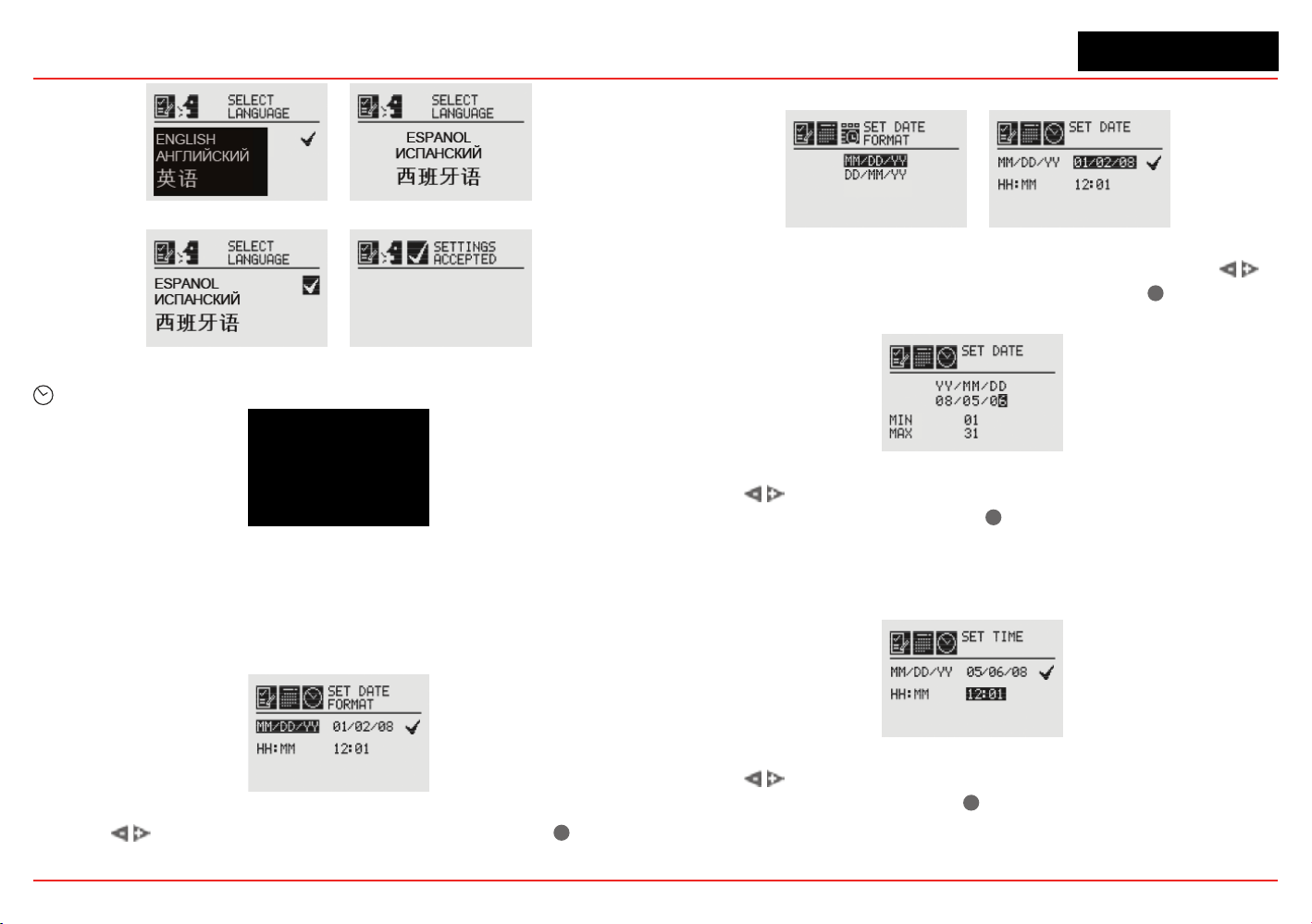
XNX Universal Transmitter
Section 2 - Installation and Operation
58
Figure 65. Language Selection Screen
Figure 66. Accept Language Change Screen
Set Date & Time
Figure 67. Set Date & Time Menu
Select “Set Date and Time” to change the date format and set
thecurrenttime/dateintotheXNX.
Set Date Format
Figure 68. Set Date Format Menu
Use the switchestohighlight“MM/DD/YY.”Select
✓
to set
the date format.
Set Date
Figure 69. Set Date Format Screen / Set Date Menu
Use the Set Date selection to set the current date. Use the
switches to select the year, month, and day. Select
✓
to set the
desired date.
Figure 70. Setting the Date Screen
Use the switches to decrement or increment the values until
the desired value appears. Select
✓
to set the value and move to
the next character. Repeat for each character to be changed.
Set Time
Figure 71. Set Time Menu
Use the switches to decrement or increment the values until
the desired value appears. Use
✓
to select the value and move
to the next character. Repeat for each character to be changed.
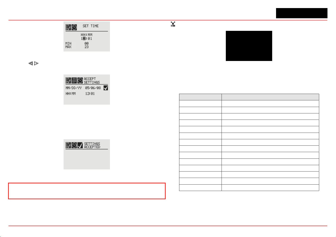
XNX Universal Transmitter
Section 2 - Installation and Operation
59
Figure 72. Set Time Screen
Use the switches to navigate to the ü. Select it to save the
changes. If ü is not selected, no changes will be saved.
Figure 73. Accept Time-Date Changes
When the new settings have been saved, the “Settings
Accepted” screen will be displayed.
Figure 74. Time-Date Settings Accepted
The remainder of this section requires Level 2 security access.
Set mV Sensor Type
Figure 75. Set mV Sensor Type Screen
Set mV Sensor Type sets the identity of the type of mV sensor
attached to the transmitter. The available mV sensor type
selections are:
Sensor Description
MPD-IC1 (5%V) MPD Carbon Dioxide 5%Vol
MPD-IV1 (5%V) MPD Methane 5%Vol
MPD-IV1 (100%L) MPD Methane 100%LEL
MPD-IF1 (100%L) MPD Flammable 100%LEL
MPD-CB1 (100%L) MPD Flammable 100%LEL
705-HT (20%L) 705 Flammable 20%LEL (High-Temp)
705-HT (100%L) 705 Flammable 100%LEL (High-Temp)
705-STD (100%L) 705 Flammable 100%LEL
SP-HT (20%L) Sensepoint Flammable 20%LEL (High-Temp)
SP-HT (100%L) Sensepoint Flammable 100%LEL (High-Temp)
SP-STD (100%L) Sensepoint Flammable 100%LEL
SP-PPM (10%L) Sensepoint Flammable PPM (10%LEL equiv)
SP-PPM Sensepoint Flammable PPM
SP-HT-NH3 Sensepoint Ammonia 30,000 PPM
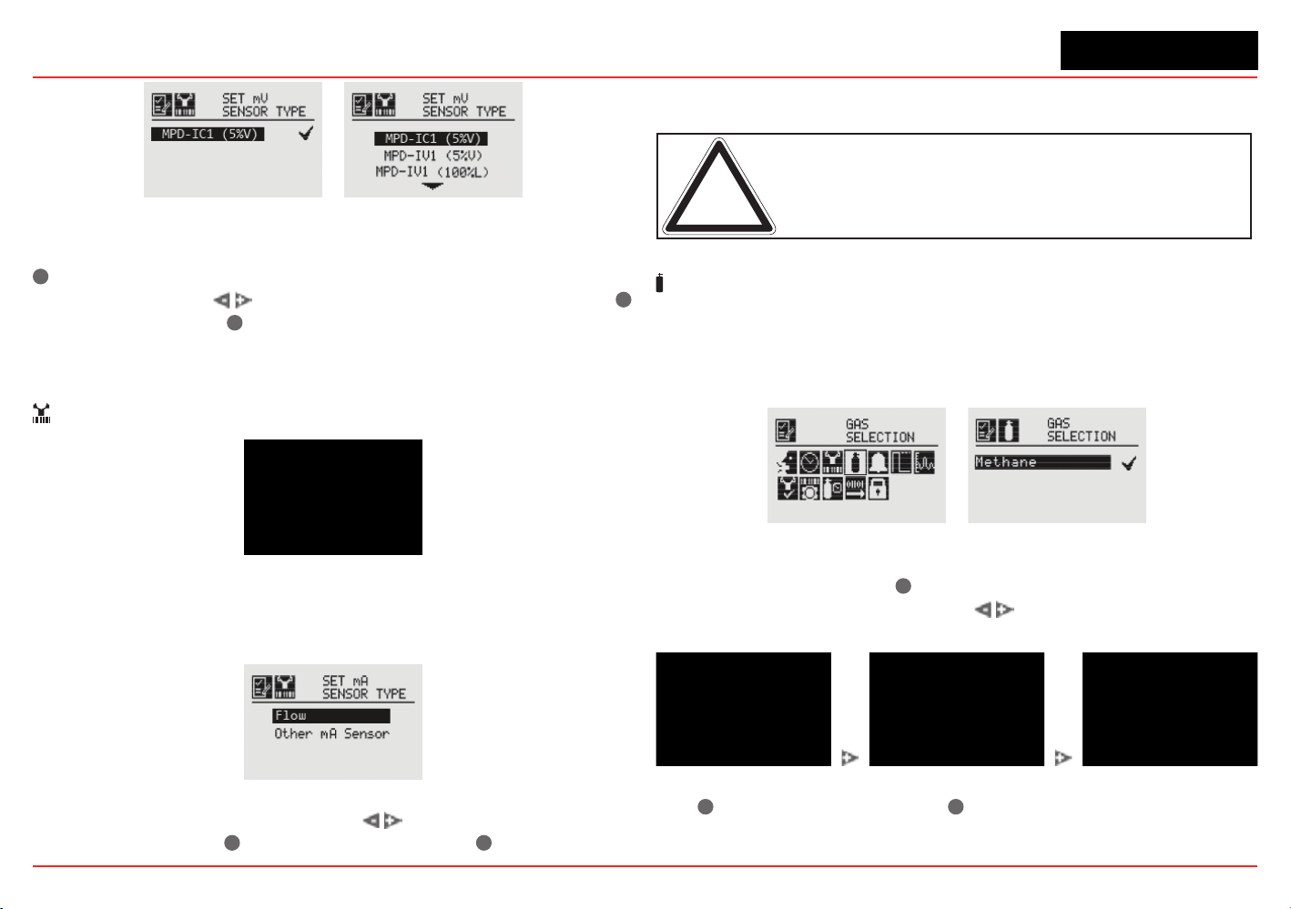
XNX Universal Transmitter
Section 2 - Installation and Operation
60
Figure 76. Current congured mV sensor and mV Available Sensor List
Therstscreendisplaysthecurrentlyconguredsensor.Select
✓
to navigate to the Sensor Selection screen. To select a new
mV sensor, use the
switches to scroll through the list. Use
✓
to select a sensor or
✖
to discard the sensor selection, retaining
the previously selected sensor, and return to the previous menu.
Set mA Sensor Type
Figure 77. Set mA Sensor Type Screen
SetmASensorTypeidentiesthetypeofmAsensorattached
tothetransmitter.TheavailablemAsensorchoicesare“Excel/
Optima” and “Other mA Sensor.”
Figure 78. mA Available Sensor List
To select a new mA sensor, use the switches to move
through the list. Use
✓
to make the selection or
✖
to discard the
selection, retain the previously selected sensor, and return to the
previous menu.
Note: This configuration option is not available for XNX transmitters
with EC sensors.
Gas Selection
Gas Selection sets the target gas for sensors capable of
detecting multiple gases. The available gases for each of the
capable sensors is determined by the device connected to the
XNX transmitter.
Figure 79. Gas Selection Menu
After selecting Gas Selection, the initial screen displays the
current target gas. Select
✓
to display the list of available gases
fortheconguredsensor.Usethe switches to scroll through
the list. A sample of the list is shown in Figure 81.
Figure 80. Available Target Gas List
Use
✓
to select the new gas or
✖
to discard the selection, retain
the previously selected gas, and return to the previous menu.
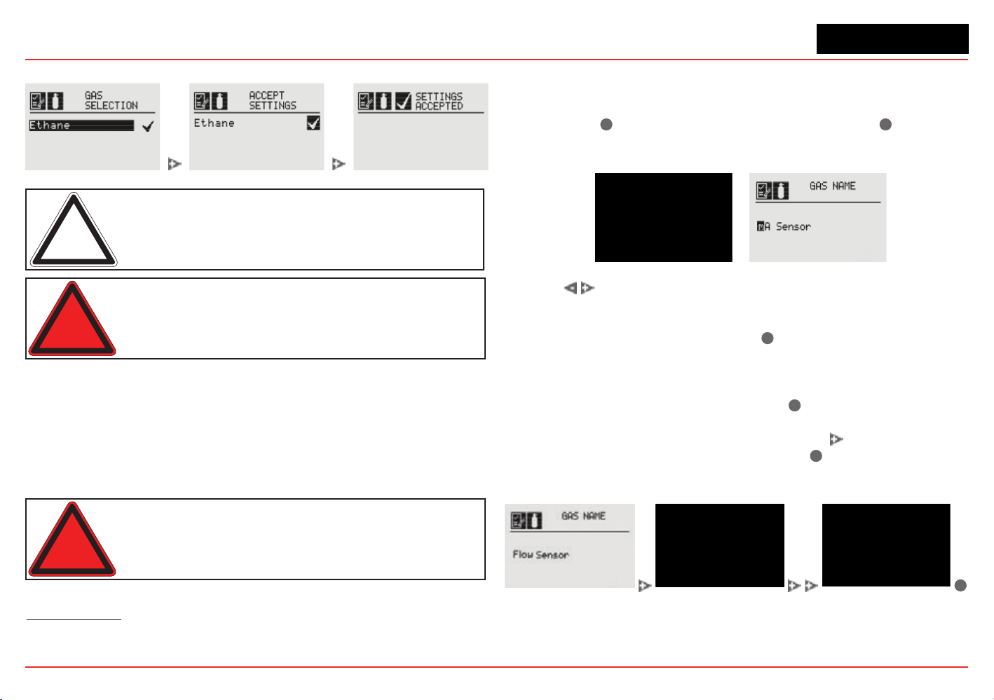
XNX Universal Transmitter
Section 2 - Installation and Operation
61
When a new gas is selected, these screens are displayed:
Figure 81. Select New Target Gas
Note: The gas selections available will vary with different types
of sensors. Gases listed with a “-2” suffix are compliant with
60079-20-1 LEL levels.
Warning: When selecting a new target gas for units with a
Searchpoint Optima Plus, the sensor must be recalibrated.
These are the XNX transmitter’s selectable gases:
• Butane (C
4
H
10
)
• Carbon Dioxide (CO
2
)
• Ethanol (C
2
H
5
OH)
• Ethylene (C
2
H
4
)
• Hexane (C
6
H
14
)
• Hydrogen (H
2
)
• Methane (CH
4
)
• Methanol (CH
3
OH)
• Propane (C
3
H
8
)
• Star 1 through Star 8
1
Warning: Do not use the XNX Universal Transmitter in oxygen-
enriched atmospheres. Concentrations displayed will be adversely
affected by oxygen depletion.
Changing the Gas or Units Name
If “Other mA Sensor” has been selected as the sensor type, the
existing gas and units can be renamed.
From the Gas Selection
menu, select
✓
to open the Gas Name menu. Select
✓
again to
opentheGasNameeditingdisplay.Therstletterofthecurrent
selection will be highlighted (Figure 82).
Figure 82. Gas Name Screen / Gas Name editing screen
Use the switches to cycle through the 76 options (26 capital
letters, 26 lower case letters, 10 numbers, 13 typographic
characters,andaspace).Whentherstcharacterofthenew
gas name has been reached, select
✓
to advance to the second
character. Repeat this procedure with each character until
the new gas name is displayed. In this example, “mA Sensor”
has been changed to “Flow Sensor” (Figure 83). The name
can be up to 15 characters long. Select
✓
to return to the Gas
Name screen. The new name will be displayed in reverse (light
characters on a dark background). Select the
switch twice to
display the Accept Settings screen. Select
✓
to accept the new
gasname.A“SettingsAccepted”screenwillbedisplayedbriey,
followed by the Gas Selection menu.
✓
Figure 83. Accepting the New Gas Name
Follow the same procedure to rename the units (“%” in the
illustrations). The units name can be up to 5 characters long.
1
In nonane detection applications, if an MPD-CB1 sensor is employed, use star rating 2; with SP-HT
sensors, use star rating 4.
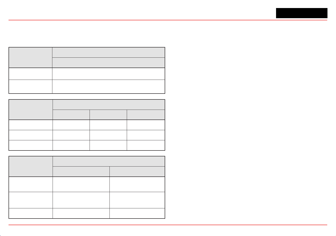
XNX Universal Transmitter
Section 2 - Installation and Operation
62
Gas Selections and Alarm Limits Based on mV Sensor Type
The following tables show the tranmsitter’s programmable alarm limits.
Note: -2 Gas Selection %LEL values are per IEC 60079-20-1:2010
MPD-IC1 (5%V)
Carbon Dioxide
Lower Alarm Limit
(% Vol)
0.5
Upper Alarm Limit
(% Vol)
5.0
MPD-IV1 (5%V/V, 100%LEL)
Methane Methane-1 Methane-2
Lower Alarm Limit
0.5% Vol 10% LEL 10% LEL
Upper Alarm Limit 5.0% Vol 60% LEL 60% LEL
% Volume Reference
n/a 5.0 4.4
MPD-IF1 (100%LEL)
Propane-1 Propane-2
Lower Alarm Limit
(% LEL)
10 10
Upper Alarm Limit
(% LEL)
60 60
% Volume Reference
2.0 1.7
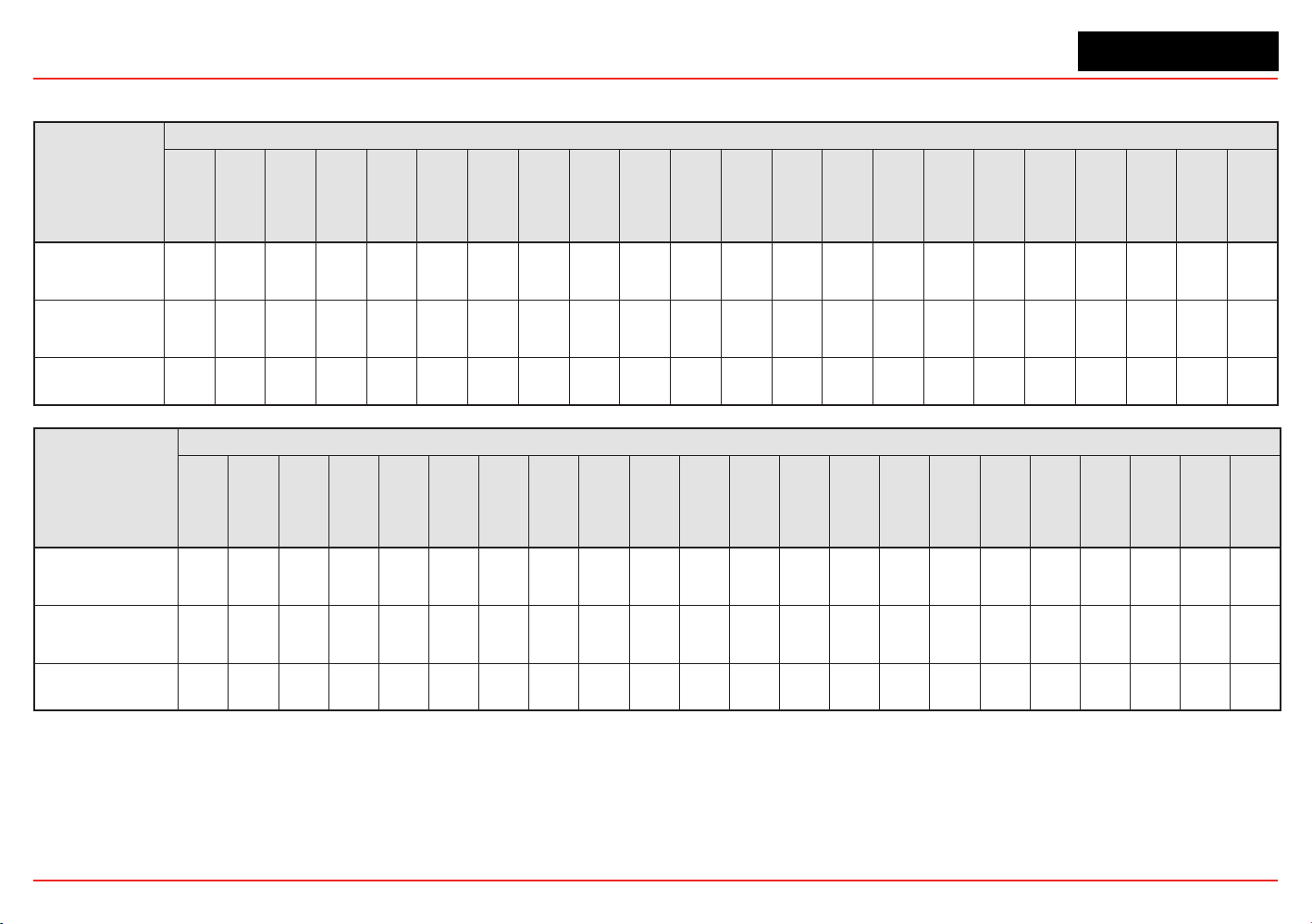
XNX Universal Transmitter
Section 2 - Installation and Operation
63
MPD-CB1 (100% LEL)
Hydrogen
Methane-1
Methane-2
Methanol
Ethelyne-1
Ethelyne-2
Ethanol-1
Ethanol-2
Propane-1
Propane-2
Butane-1
Butane-2
Hexane-1
Hexane-2
Star 1
Star 2
Star 3
Star 4
Star 5
Star 6
Star 7
Star 8
Lower Alarm
Limit (% LEL)
10 10 10 10 10 10 10 10 10 10 10 10 10 10 20 20 20 10 10 10 10 10
Upper Alarm
Limit (% LEL)
60 60 60 60 60 60 60 60 60 60 60 60 60 60 60 60 60 60 60 60 60 60
% Volume
Reference
4.0 5.0 4.4 5.5 2.7 2.3 3.3 3.1 2.0 1.7 1.5 1.4 1.2 1.0 n/a n/a n/a n/a n/a n/a n/a n/a
705-STD (100% LEL)
Hydrogen
Methane-1
Methane-2
Methanol
Ethelyne-1
Ethelyne-2
Ethanol-1
Ethanol-2
Propane-1
Propane-2
Butane-1
Butane-2
Hexane-1
Hexane-2
Star 1
Star 2
Star 3
Star 4
Star 5
Star 6
Star 7
Star 8
Lower Alarm
Limit (% LEL)
20 20 20 25 25 30 30 30 25 30 30 30 50 50 50 30 25 20 20 20 15 15
Upper Alarm
Limit (% LEL)
60 60 60 60 60 60 60 60 60 60 60 60 60 60 60 60 60 60 60 60 60 60
% Volume
Reference
4.0 5.0 4.4 5.5 2.7 2.3 3.3 3.1 2.0 1.7 1.5 1.4 1.2 1.0 n/a n/a n/a n/a n/a n/a n/a n/a
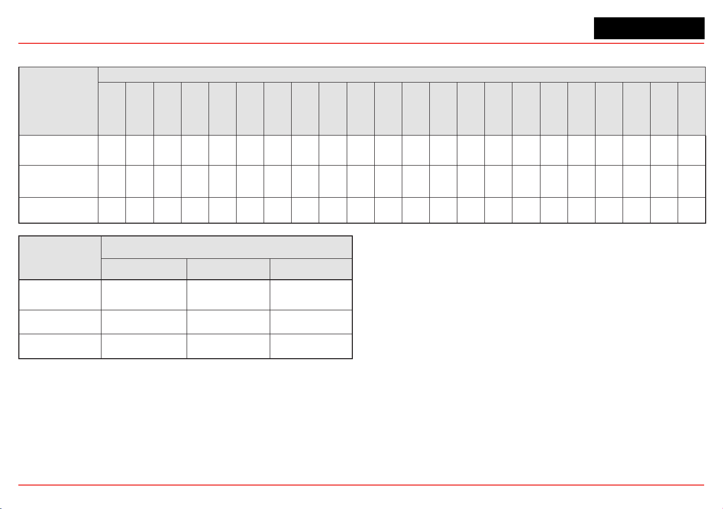
XNX Universal Transmitter
Section 2 - Installation and Operation
64
705-HT (100% LEL)
Hydrogen
Methane-1
Methane-2
Methanol
Ethelyne-1
Ethelyne-2
Ethanol-1
Ethanol-2
Propane-1
Propane-2
Butane-1
Butane-2
Hexane-1
Hexane-2
Star 1
Star 2
Star 3
Star 4
Star 5
Star 6
Star 7
Star 8
Lower Alarm
Limit (% LEL)
20 15 20 20 20 20 20 20 20 20 20 20 20 20 50 30 25 20 20 20 15 15
Upper Alarm
Limit (% LEL)
60 60 60 60 60 60 60 60 60 60 60 60 60 60 60 60 60 60 60 60 60 60
% Volume
Reference
4.0 5.0 4.4 5.5 2.7 2.3 3.3 3.1 2.0 1.7 1.5 1.4 1.2 1.0 n/a n/a n/a n/a n/a n/a n/a n/a
705-HT (20% LEL), SP-HT (20% LEL)
Hydrogen Methane-1 Methane-2
Lower Alarm Limit
(% LEL)
5.0 5.0 5.0
Upper Alarm Limit
(% LEL)
20 20 20
% Volume
Reference
4.0 5.0 4.4
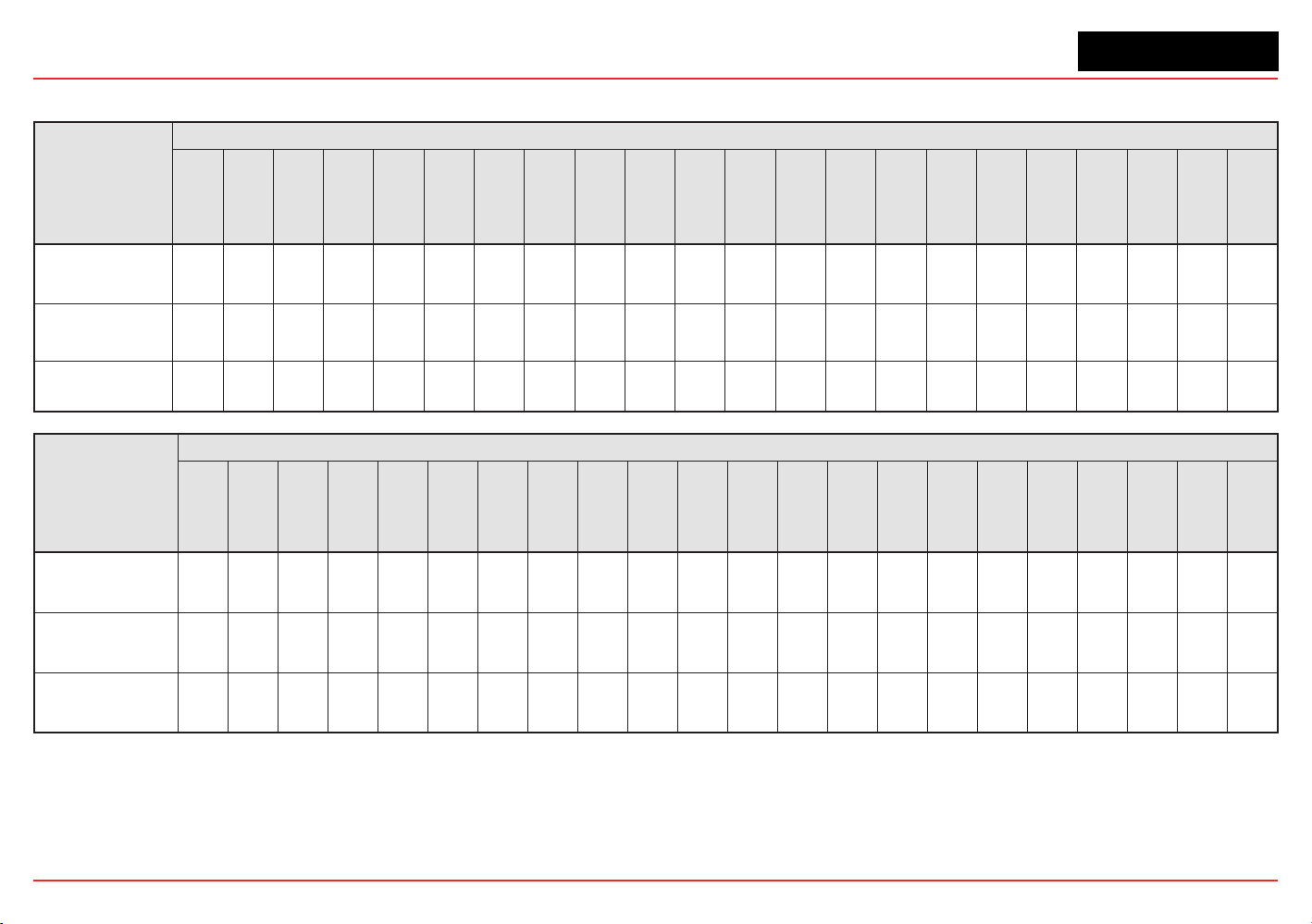
XNX Universal Transmitter
Section 2 - Installation and Operation
65
SP-STD (100% LEL)
Hydrogen
Methane-1
Methane-2
Methanol
Ethelyne-1
Ethelyne-2
Ethanol-1
Ethanol-2
Propane-1
Propane-2
Butane-1
Butane-2
Hexane-1
Hexane-2
Star 1
Star 2
Star 3
Star 4
Star 5
Star 6
Star 7
Star 8
Lower Alarm
Limit (% LEL)
20 15 20 20 20 20 20 20 20 20 20 20 20 20 50 30 25 20 20 20 15 15
Upper Alarm
Limit (% LEL)
60 60 60 60 60 60 60 60 60 60 60 60 60 60 60 60 60 60 60 60 60 60
% Volume
Reference
4.0 5.0 4.4 5.5 2.7 2.3 3.3 3.1 2.0 1.7 1.5 1.4 1.2 1.0 n/a n/a n/a n/a n/a n/a n/a n/a
SP-HT (100% LEL)
Hydrogen
Methane-1
Methane-2
Methanol
Ethelyne-1
Ethelyne-2
Ethanol-1
Ethanol-2
Propane-1
Propane-2
Butane-1
Butane-2
Hexane-1
Hexane-2
Star 1
Star 2
Star 3
Star 4
Star 5
Star 6
Star 7
Star 8
Lower Alarm
Limit (% LEL)
10 10 10 10 10 10 10 10 10 10 10 10 10 10 20 20 20 10 10 10 10 10
Upper Alarm
Limit (% LEL)
60 60 60 60 60 60 60 60 60 60 60 60 60 60 60 60 60 60 60 60 60 60
% Volume
Reference
4.0 5.0 4.4 5.5 2.7 2.3 3.3 3.1 2.0 1.7 1.5 1.4 1.2 1.0 n/a n/a n/a n/a n/a n/a n/a n/a
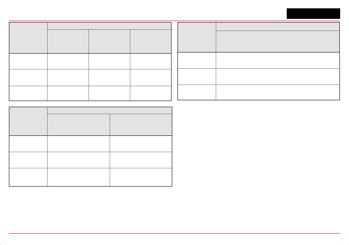
XNX Universal Transmitter
Section 2 - Installation and Operation
66
SP-PPM (10% LEL)
Hydrogen Methane-1 Methane-2
Lower Alarm
Limit (% LEL)
2.0 2.0 2.0
Upper Alarm
Limit (% LEL)
10 10 10
% Volume
Reference
4.0 5.0 4.4
SP-PPM
Hydrogen Methane
Lower Alarm
Limit (% LEL)
1000 ppm 1000 ppm
Upper Alarm
Limit (% LEL)
5000 ppm 5000 ppm
% Volume
Reference
n/a n/a
SP-HT-NH3
Ammonia
Lower Alarm
Limit (% LEL)
3000 ppm
Upper Alarm
Limit (% LEL)
30000 ppm
% Volume
Reference
n/a
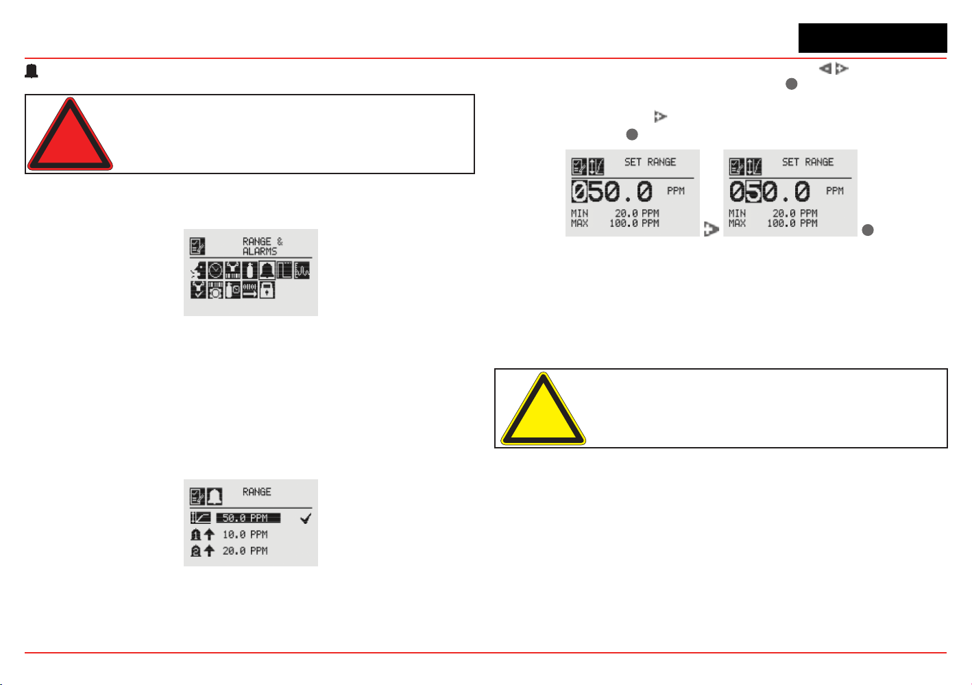
XNX Universal Transmitter
Section 2 - Installation and Operation
67
Range & Alarms
Warning: XNX Universal Transmitters carrying UL/CSA approvals
that are configured for devices measuring %LEL will not allow
adjustments to the full scale value. The range is fixed at 100%.
The Range & Alarms option applies only to units with
certicationsotherFthanUL/CSA.
Figure 84. Range & Alarms Menu
Set Range (full-scale)
Range is sensor dependent. The Set Range option allows the
full-scale range to be set for the sensor which is attached to the
transmitter. The full-scale range is based on the capability of the
sensor.TheselectablerangeforECsensorsisdenedinthe
Selectable Range column of the table in Section 6.3.2. The selectable
rangeforcatalyticbeadsensorsisdenedintheSelectableRange
column of the table in Section 6.3.5.
Figure 85. Range Option
When the Range option is highlighted, use the switches
to decrement or increment the value. Use
✓
to accept the
displayedvalueandmovetothenexteld.Whenalleldshave
been updated, use the switch to highlight ü on the right side
of the display. Use
✓
to accept the changes.
✓
Figure 86. Setting the Range Value
When complete, the display will return to the Range Option
screen.
Set Alarm Values
Set Alarm Values allows the values for Alarm Direction and Alarm
Limits for both Alarm 1 and Alarm 2 to be set.
Caution: Alarm 1 and Alarm 2 values must be less than the Upper
Limit value.
Use Alarm Direction to establish whether the alarm is to be
triggered by rising or falling gas concentrations. Alarms for
most target gases are triggered by rising concentration levels
butcertaingases;e.g.,oxygen,canbemeasuredfordepletion
levels.WhentheXNXtransmitterisconguredwithmVor
OPTIMA sensors and the meaurement units are LEL, the alarm
level setting is limited to 60%LEL.
If the concentration of the target gas remains above the alarm
values for 3 seconds or more, an alarm will be triggered.
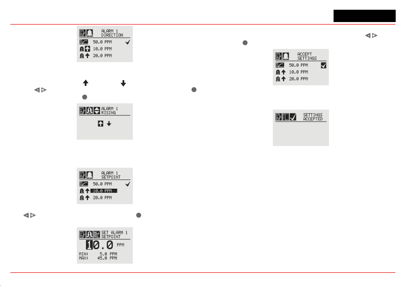
XNX Universal Transmitter
Section 2 - Installation and Operation
68
Figure 87. Alarm Direction
The icons next to the bell images indicate whether the alarm has
been triggered by rising (
) or falling ( ) gas concentrations.
Use the switches to highlight the appropriate trigger. Use
✓
to make the selection or
✖
to discard it.
Figure 88. Setting Alarm Rising/Falling
The Alarm Limits selection sets the alarm trigger level for both
alarms.
Figure 89. Alarm Limits
Use to set the desired alarm limit and
✓
select it. Repeat
for each alarm.
Figure 90. Setting an Alarm Setpoint
When complete, the display will return to the main Range &
Alarm screen. When all settings have been made, use
to
move to the
✓
on the display to Accept Settings.
Figure 91. Accept Settings
When the settings have been saved, the following screen will
appear on the display.
Figure 92. Settings Accepted Screen
See Section 6.1ProductSpecications for EC cell information.
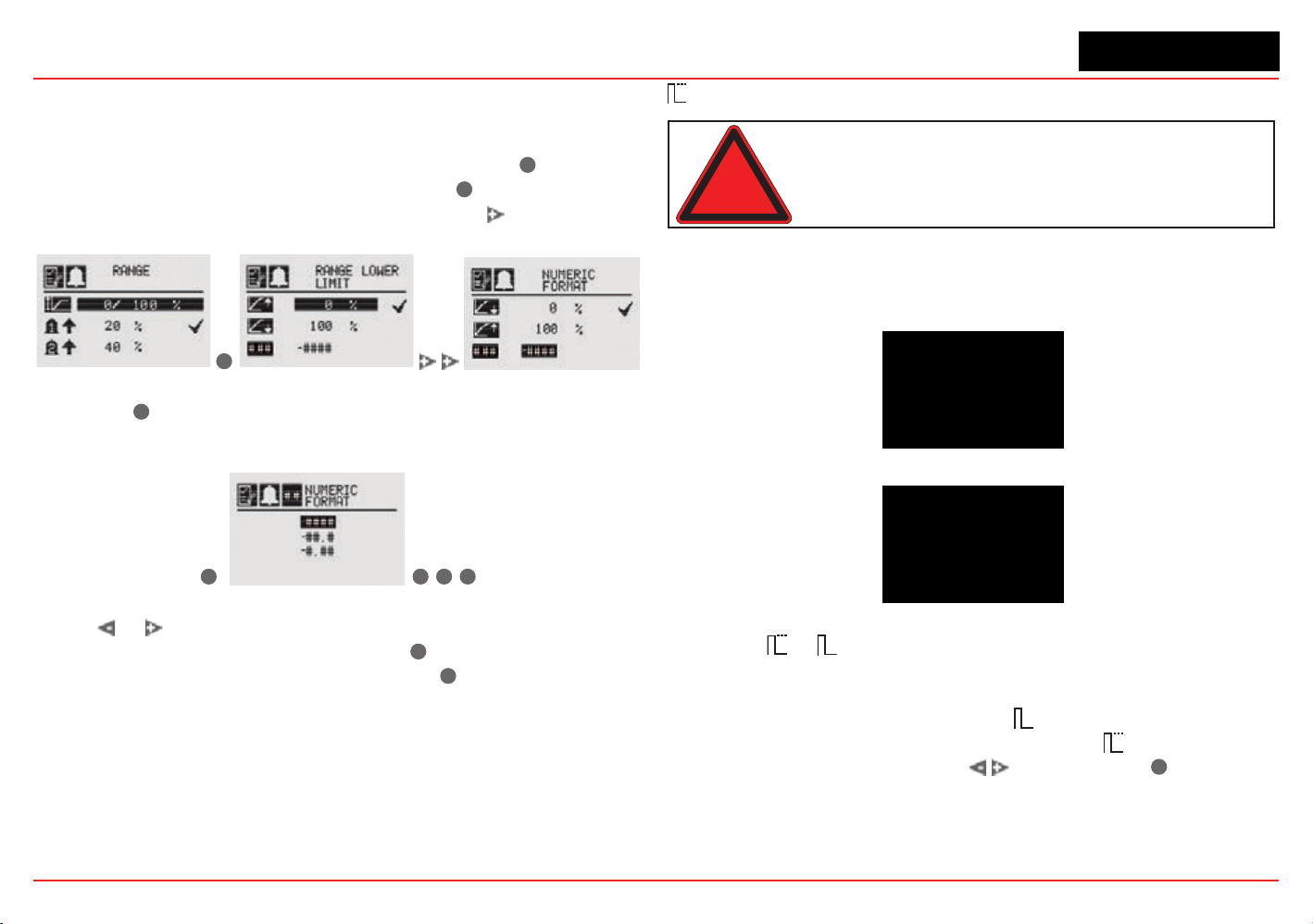
XNX Universal Transmitter
Section 2 - Installation and Operation
69
Selecting the Numeric Format
If “Other mA Sensor” has been selected as the sensor type, the
transmitter’s output can be displayed in one of three numeric
formats. From the Ranges & Alarms menu, select the
✓
switch to
open the Range menu (Figure 93). Select the
✓
switch again to
display the Range Lower Limit menu. Select the switch twice
to open therstNumericFormatmenu.
✓
Figure 93. Navigating to the rst Numeric Format menu
Select the
✓
switch to open the second Numeric Format menu,
which displays the formats available for numerical display (see
Figure 94).
✓
✓
✖
✖
Figure 94. Navigating to the second Numeric Format menu
Select or to cycle through the three options. When the
desired format is highlighted, select the
✓
switch to make the
selection the default display format. Select
✖
twice to return to
the Ranges & Alarms menu.
Latching / Non-Latching
Warning: There is a potential loss of sensitivity during exposure to high
concentrations of H
2
S. Under these conditions, set the control unit to latch
at overrange. In standalone configuration, set alarms to latching. When
resetting the overrange or alarm, verify correct operation of the transmitter.
Latching/Non-LatchingisusedtocontrolwhetherAlarms1and
2 and faults will latch alarms.
Figure 95. Alarm Latching/Non-Latching Screen
Figure 96. Alarm Latching
Select the
or
icon beside the alarm limit to display the
AlarmLatching/Unlatchingscreen.Alarmlatchingdetermines
whether alarms that are triggered are automatically reset when
the condition dissipates (latching off
) or remain active until
an operator resets them manually (latching on
). Highlight the
desired latching option with the switches. Use
✓
to accept
it.
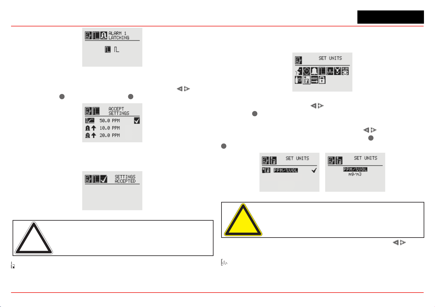
XNX Universal Transmitter
Section 2 - Installation and Operation
70
Figure 97. Setting Alarm Latching/Unlatching
Use the same procedure to set the desired values for Alarm
2 and Faults. When all settings have been made, use
to
navigate to the
✓
on the display. Use
✓
to accept settings.
Figure 98. Accept Settings
When the settings have been saved, the following screen is
displayed.
Figure 99. Settings Accepted Screen
Note: When non-latching is selected, external alarm latching is
recommended.
Set Units
The Set Units menu allows the units of measurement displayed
on the XNX main menu to be set. This option also sets the units
transmitted via HART, Modbus, or Foundation Fieldbus sensors
attached to the XNX transmitter, reporting concentrations in PPM
or %VOL (except oxygen).
Figure 100. Set Units Menu
To change the units, use the switches to highlight the units
icon. Use
✓
to select it. The transmitter’s display will change
to the Display Unit Selection screen which shows the available
choices for the sensor type installed. Use the switches to
highlight the desired unit of measurement. Use
✓
to select it or
✖
to discard the selection.
Figure 101. Display Unit Selection Screen
Caution: When changing units of measure, check alarm level
settings for the proper units and change as necessary.
Once the units of measurement have been set, use the
switches to navigate to the ‘ü’ to accept the values.
mA Levels
This option allows the user to select mA output levels for inhibit,
fault, and over range. Beam block and low signal apply to
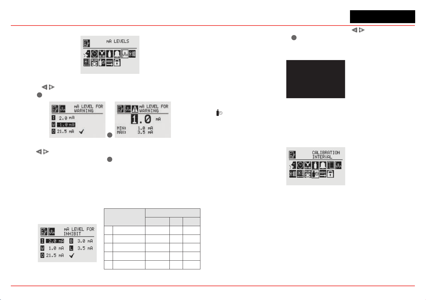
XNX Universal Transmitter
Section 2 - Installation and Operation
71
Searchline (see the table in the next column).
Figure 102. mA Levels Menu
Using the switches, move to the mA output to be changed
and use
✓
to select it.
✓
Figure 103. Set mA Levels for Warning
Use the switches to decrement or increment the value until
the desired value appears. Use
✓
to select the value and move
to the next setting. Repeat for each setting to be changed.
The default values and available output ranges for Inhibit,
Warning, Overrange, Beam Blocked, and Low Signal are shown
in the following table. See Section
5Warnings/Faults for more
information.
Signal
Output (mA)
Default Min Max
I
Inhibit 2.0 1.0 3.5
W
Warning 3.0 1.0 3.5
O
Overrange 21.0 20 22
B
Beam Blocked 1.0 1.0 4.0
L
Low Signal 1.0 1.0 4.0
Figure 104. Set mA Levels for Inhibit
After all changes have been made, use the switches to
move to the ‘ü’ and use
✓
on the front panel to accept and save
the settings. If ‘ü’ is not selected, none of the changes will be
saved.
Figure 105. mA Settings Saved
Calibration Interval
Calibration Interval allows a desired interval for sensor
calibration to be set for sensors attached to the transmitter. The
transmitter will generate a warning when the interval is reached.
Figure 106. Calibration Interval Menu
Calibration Interval will not appear when an IR personality board
is attached and the mA sensor type is set as ‘Other mA Sensor’.
The default calibration values for the “Calibration Required”
diagnostic vary based on sensor type. This value can be repro-
grammed in accordance with site requirements to ensure the
highest level of safety. Correct operation of each sensor should
beconrmedusingcalibrationwithacertiedgasofknowncon-
centration before commissioning.
Although the calibration Interval can be set to any value be-
tween 0 and 360 days, Honeywell Analytics recommends that the
interval for electrochemical and catalytic sensors be set to 180
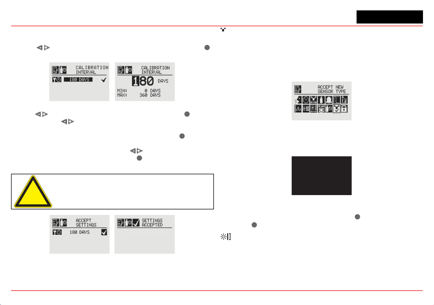
XNX Universal Transmitter
Section 2 - Installation and Operation
72
days (or fewer, in accordance with customer site procedures) to
assure the highest level of safety.
Use the
switches to highlight the current interval and use
✓
to select it.
Figure 107. Edit Interval and Setting Interval Value Screens
Use the switches to move to the desired position. Use
✓
to
select it. Use the
switches to decrement or increment the value
untilthedesiredvalueisreached.(Theminimumnumberofdaysis0;
themaximumnumberisdenedbythesensortype.)Use
✓
to select
thevalueandmovetothenexteld.Repeatforeacheld.Whenall
oftheeldshavebeenupdated,usethe switches to highlight
the
‘ü’
on the right side of the display. Use
✓
on the front panel to
save the settings.
Caution: Setting the Calibration Interval to zero turns off the
calibration notification. This can seriously affect sensor performance.
Figure 108. Saving New Interval and New Interval Accepted Screens
✓
Accept New Sensor Type
When replacing EC cells or mV sensors, use Accept New Sensor
Type to load default parameters into the XNX transmitter for
calibration and sensor life. Accept New Sensor Type is also used
when replacing an EC cell with another EC cell for a different
target gas. (See Section 4.2.2).
Figure 109. Accept New Sensor Type Menu
When changing the target gas by inserting a new sensor, the
transmitterwillprompttheuserforaconrmationofthechange
before adjusting to the properties of the new sensor.
Figure 110. Select New Sensor
In the display of the XNX transmitter, the old sensor type and
the new sensor type will be displayed. Use
✓
to accept the new
sensor or
✖
to reject it.
Beam Block Options
The Beam Block Options menu is available only if the XNX
transmitter is connected to a Searchline Excel sensor.

XNX Universal Transmitter
Section 2 - Installation and Operation
73
Figure 111. Beam Block Menu
If the infrared beam from the Excel transmitter is blocked or
inhibited in such a way that the intensity of the beam drops to a
level below the readable threshold set by the receiver, a warning
will be generated by the XNX transmitter. The Beam Block
Optionsmenuallowstheusertodenethemaximumperiodof
time the infrared beam can be blocked and the percentage of
signal loss before generating a warning through the transmitter.
Figure 112. Beam Block Warning Time
Use the switches to move to the desired beam block
time option and use
✓
to select it. Use the switches
to decrement or increment the value until the desired value
appears. Use
✓
to select the value and move to the next setting.
Figure 113. Setting Beam Block Warning Time
When the beam is blocked longer than the value set in Time to
Beam Block, a fault is generated by the transmitter.
Set Time to Fault sets the minimum time the beam is blocked
before generating a fault.
Figure 114. Beam Block Fault Time
Use the switches to move to the desired beam block
time option and use
✓
to select it. Use the switches
to decrement or increment the value until the desired value
appears. Use
✓
to select the value and move to the next setting.
Figure 115. Setting Beam Block Fault Time
When the beam is blocked longer than the value set in Time to
Fault, a fault is generated by the transmitter.
Low Signal Percentage sets the minimum percentage value of
the beam that is not blocked. When the percentage decreases
belowthedenedpercentage,afaultisgenerated.
Figure 116. Low Signal Percentage
Use the switches to move to the desired Low Signal
Percentage and use
✓
to select it. Use the switches
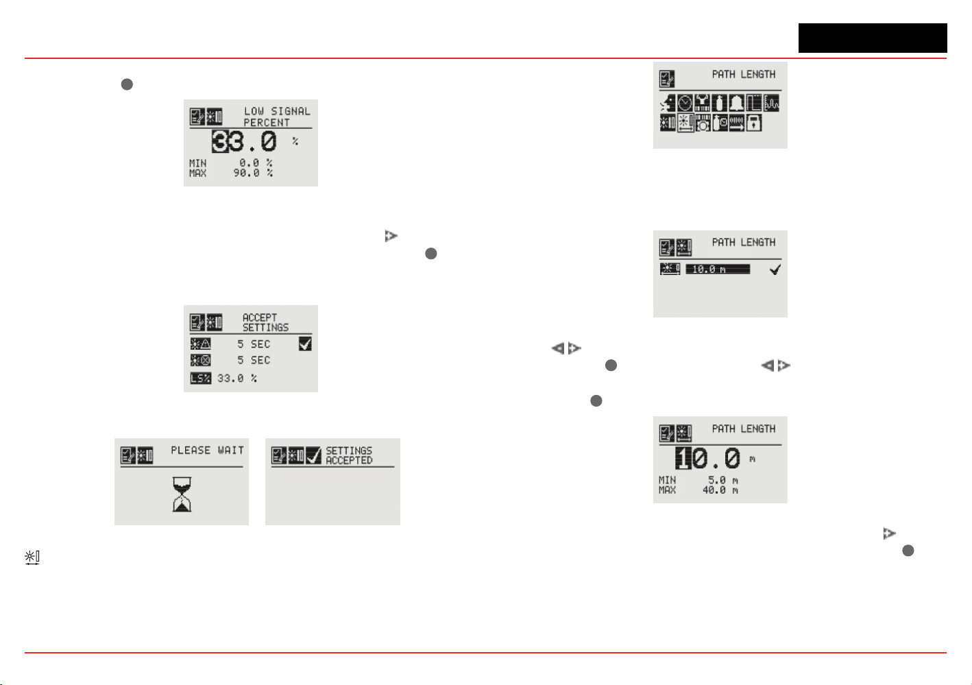
XNX Universal Transmitter
Section 2 - Installation and Operation
74
to decrement or increment the value until the desired value
appears. Use
✓
to select the value and move to the next setting.
Figure 117. Setting the Low Signal Percentage
Once the values for Beam Block Warning, Beam Block Fault
and Low Signal Percentage have been set, use the
switch to
highlight the ‘ü’ on the right side of the display. Then use
✓
to
accept the changes to the XNX. If ‘ü’ is not highlighted, none of
the changes will be saved.
Figure 118. Accept Beam Block Changes
Figure 119. Beam Block Changes Accepted
Path Length
The distance (in meters) between the transmitter and the receiver
is set through the Path Length menu. This menu is available only
if the transmitter is connected to a Searchline Excel sensor.
Figure 120. Path Length Menu
Setting the Path Length or distance between the transmitter and
receiver of the Excel lets the devices determine the optimum
settings for the beam strength for the application.
Figure 121. Current Path Length Setting
Use the switches to move to the desired Path Length
setting and use
✓
to select it. Use the switches to
decrement or increment the value until the desired value
appears. Use
✓
to select the value and move to the next setting.
Figure 122. Setting Path Length
Once the values for Path Length have been set, use the switch
to highlight the ‘ü’ on the right side of the display. Use the
✓
to
accept the changes.
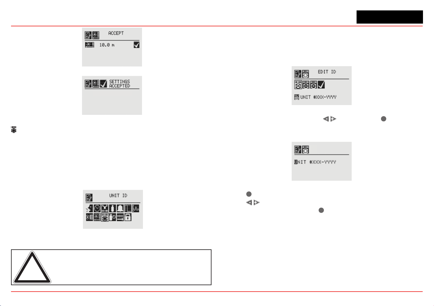
XNX Universal Transmitter
Section 2 - Installation and Operation
75
Figure 123. Accepting Path Length Changes
Figure 124. Path Length Changes Accepted
Unit ID
The Unit ID option allows a unique unit ID of up to 18 characters
to be set for each XNX transmitter. This character string can be
broadcast over any of the supported communication options,
providingameanstocreateauniqueidenticationforeachXNX
transmitter for accurate reporting. Available characters are A-Z,
a-z,0-9andspecialcharacters?!*%():&/,#+-
Figure 125. Unit ID Menu
Note: The XNX Unit ID is not the same as the HART tag in XNX
applications using HART protocol.
Edit ID
Each XNX is assigned a default Unit ID from the factory. The Edit
IDmenuallowstheassignedIDtobemodied.
Figure 126. Edit Unit ID Screen
From the Edit ID Screen, use the switches and
✓
to select
Edit ID. The current Unit ID is displayed. When editing an existing
ID, the list of available characters begins at the value displayed.
Figure 127. Editing the Unit ID
Use the
✓
switchtohighlighttherstcharactertobechanged.
Use the switches to decrement or increment the value until
the desired value appears. Use
✓
to accept the new value and
move to the next character. Repeat for each character to be
changed. The Unit ID can be up to18 characters long.
Clear ID
This option clears the current set Unit ID.
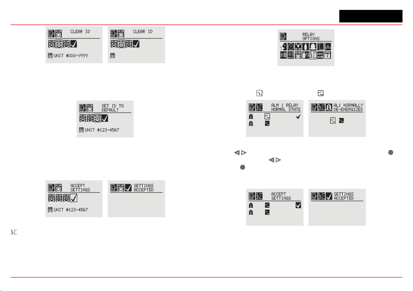
XNX Universal Transmitter
Section 2 - Installation and Operation
76
Figure 128. Clear Unit ID and Cleared Unit ID Screens
Set ID to Default
The Set ID to Default option returns the Unit ID to the factory
default.
Figure 129. Set ID to Default Screen
Once all changes have been made, Accept Settings must be
selected before exiting the Unit ID menu. When all changes
are saved, the transmitter will display the Settings Accepted
screen.
Figure 130. Accept Settings and Accepted Screens
Relay Options
The Relay Options menu allows the relays for both alarm
levelstobecongured.ThismenuisavailableonlyiftheXNX
transmitter is equipped with the optional relays.
Figure 131. Relay Options Screen
XNXrelayscanbesettoEnergizedorDe-energized.Thedefault
isDe-energized.Thetwostatesforeachrelayarerepresented
by the symbols forenergizedand forde-energized.
Figure 132. Alarm 1 Relay Current State and Setting New State
Use the switches to move to the desired alarm and use
✓
to select it. Use the
switches to change the state of the
relay. Use
✓
to accept the new state. Once the XNX transmitter
has accepted the new information, a Settings Accepted screen
appears.
Figure 133. Accept New Alarm Relay Settings and new Settings Accepted
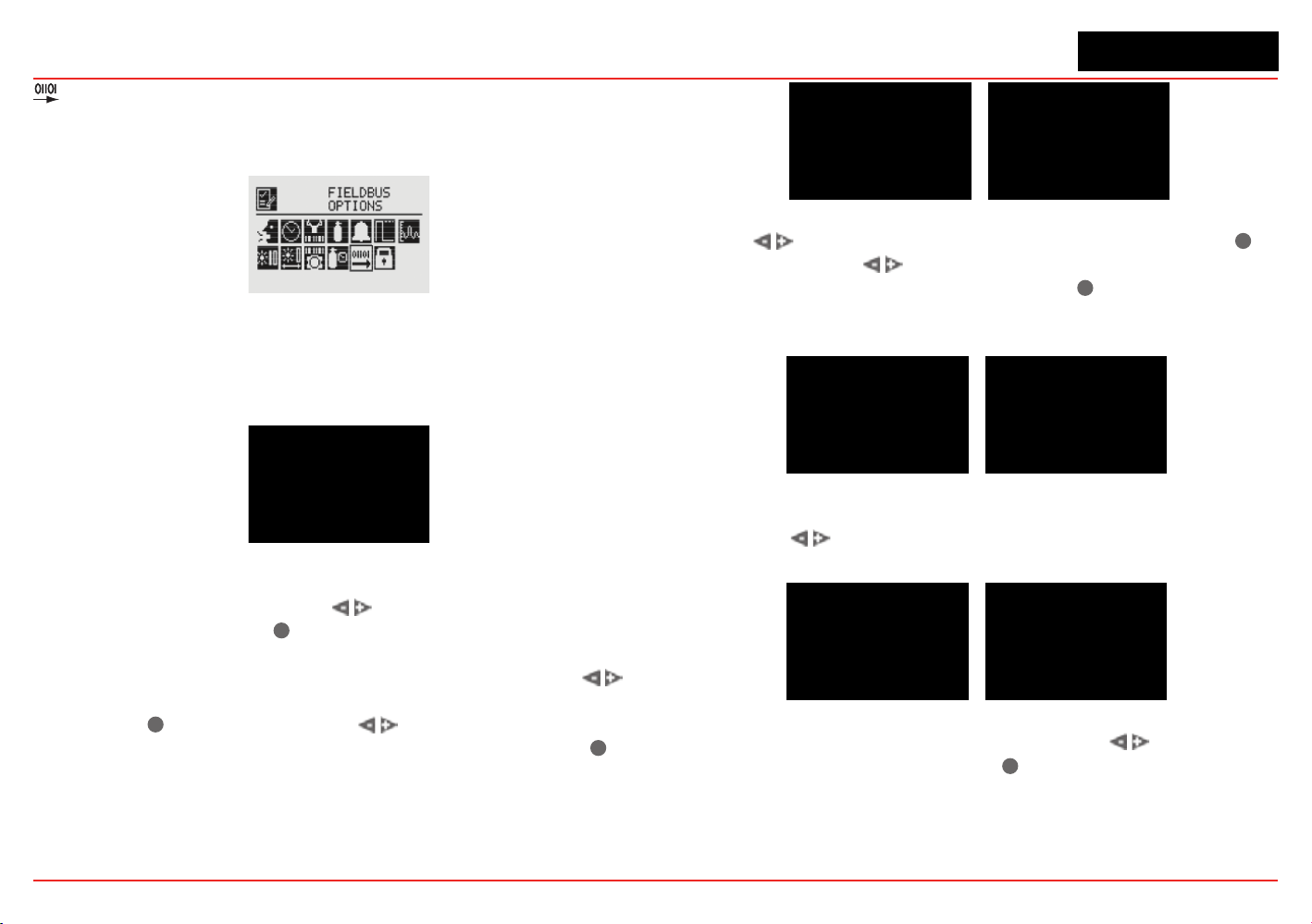
XNX Universal Transmitter
Section 2 - Installation and Operation
77
Fieldbus Options
TheFieldbusOptionsmenuallowscongurationoftheHART
addressortheoptionalModbuseldbusaddressandbaudrate.
Figure 134. Fieldbus Options Screen
SelecttheFieldbusOptionsicontoactivatetheHART/Modbus
screenstoallowselectionoftheprotocolstobeconguredor
changed.IftheXNXisconguredwithoutHARTorModbus,only
the installed options will be visible.
Figure 135. HART Options Screen
The HART menu provides the ability to select the HART mode.
From the HART screen, use the
switches to highlight the
HART option, then select
✓
. This displays the HART address
screen where the device address and whether the HART protocol
is active in the unit can be set. To set the address, use the
switches to highlight the number in the top line (between 0 and
63) and use
✓
to select it. Use the switches to decrement
or increment the value until the desired value appears. Use
✓
to
select the value and move to the next setting.
Figure 136. HART Address and Address Value Screens
Use the switches to move to the HART option and use
✓
to select it. Use the
switches to scroll through the options
until the desired option is highlighted. Use
✓
to accept the new
state. See Section 2.3.1 and Appendix A for more information
on available HART modes.
Figure 137. HART Mode Screens
Once the values for the HART address and Mode have been
set, use the
switches to navigate to the ‘ü’ then select it to
save the changes to the XNX.
Figure 138. HART Settings Accepted
When the Modbus option is available, use the switches to
move to the Modbus icon and use
✓
to select it. The Modbus
option allows the address and communication baud rate to be
set.
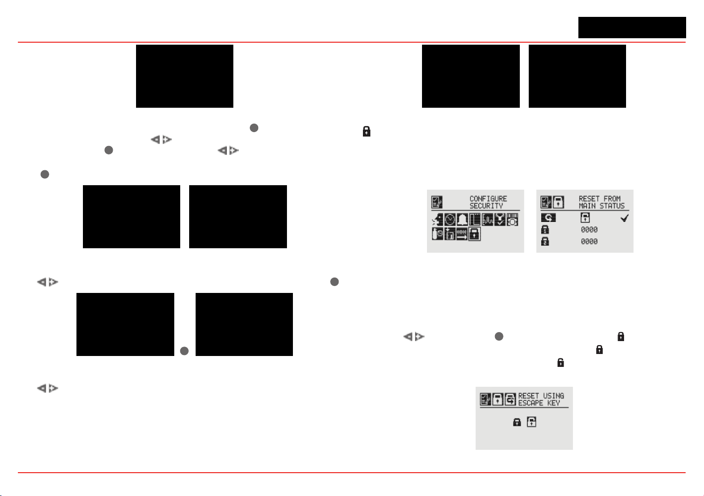
XNX Universal Transmitter
Section 2 - Installation and Operation
78
Figure 139. Modbus Options Screen
From the Set Fieldbus Address screen, select
✓
. To set the
Fieldbus address, use the
switches to move to the desired
position and use
✓
to select it. Use the switches to
decrement or increment the value until the desired value appears.
Use
✓
to select the value and moves to the next setting.
Figure 140. Set Fieldbus Address and Address Value Screens
The communications baud rate can be set from this screen. Use
the switches to highlight the proper baud rate and select
✓
.
✓
Figure 141. Set Baud Rate Screens
Once the values for the Fieldbus address have been set, use
the
switches to navigate to the ‘ü’ then select it to save the
changes.
Figure 142. Accept Settings and Fieldbus Address Settings Accepted
Congure Security
CongureSecurityisusedtosetorresetthelevel1andlevel
2passcodesthatcontrolaccesstothecongurationmenusof
the XNX transmitter.
Figure 143. Congure Security Screens
Easy Reset from Main Status
The Easy Reset from Main Status option controls the ability
to reset faults, warnings, and alarms from the General Status
screen (see Section 1.4.2).
Use the switches and
✓
to select the lock icon .TheLock/
Unlock screen will be displayed. Choose ‘Lock’ to prevent reset
without password access. The ‘Unlock’ choice allows resets
without requiring login or a passcode.
Figure 144. Lock/Unlock Screen
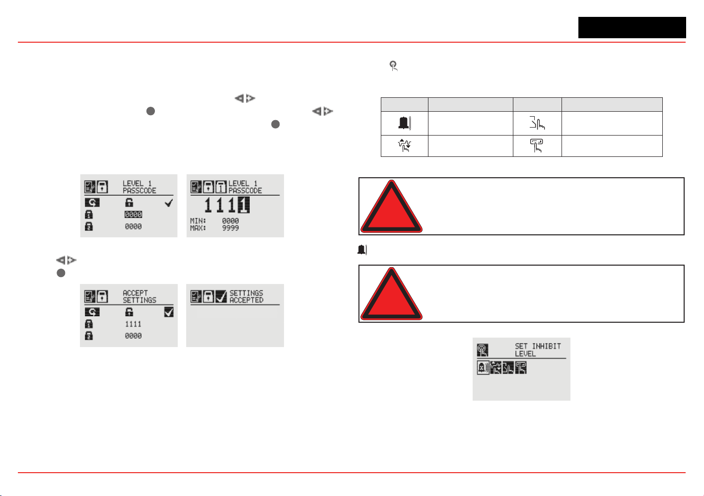
XNX Universal Transmitter
Section 2 - Installation and Operation
79
Level 1 and Level 2 Passcode
Level 1 and 2 passcode screens give the administrator the ability
to assign new passcodes for either or both access levels.
FromtheCongureSecurityScreen,usethe switches to
highlight Passcode 1. Use
✓
tochoosetherstdigitandthe
switches to decrement or increment the values. Use
✓
to accept
the new value and move to the next digit. Repeat until all four digits
have been selected. Follow the same procedure to change the
Level 2 passcode.
Figure 145. Setting Level 1 Passcode
Use the switches to move to “Accept Settings” on the display.
Choose
✓
to save the settings to the transmitter.
Figure 146. Accept Settings and Security Settings Accepted Screens
2.6 Verifying the XNX Conguration
2.6.1 Test Menu
The test menu icons are shown in this table:
Symbol Description Symbol Description
X
Inhibit Force Relay
Force mA Output Alarm/FaultSimulation
Warning: Keep the passwords in a secure area to prevent
unauthorized access to the transmitter. If the passwords are lost,
resetting the XNX transmitter will require a service technician.
X
Inhibit
Warning: When the XNX transmitter is placed in Inhibit Mode,
alarms are silenced. This will prevent an actual gas event from being
reported. Inhibit Mode must be limited to testing and maintenance
only. Exit Inhibit Mode after testing or maintenance activities.
Figure 147. Inhibit Screen
The Inhibit mode is designed to prevent alarms from being
triggered during testing or maintenance.
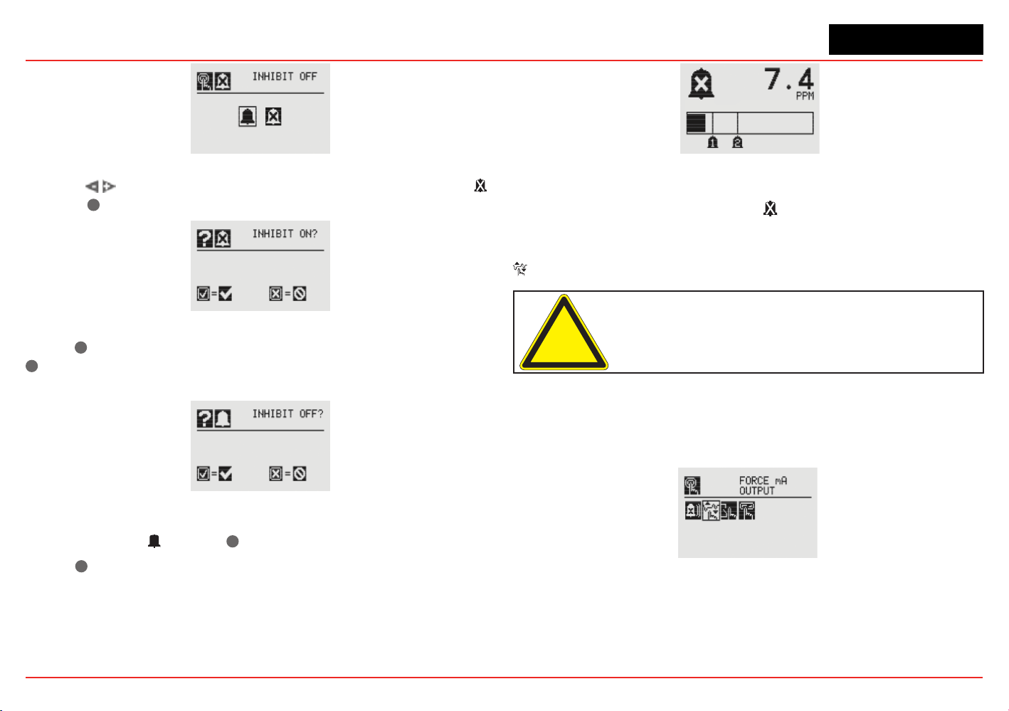
XNX Universal Transmitter
Section 2 - Installation and Operation
80
Figure 148. Inhibit Menu
Use the switches to inhibit alarms by selecting Inhibit On
with the
✓
.Theconrmationscreenappears.
Figure 149. Conrm Inhibit On
Select
✓
to place the transmitter alarms into inhibit mode. Select
✖
will cancel the choice and leave the alarms in normal operating
mode.
Figure 150. Conrm Inhibit Off
To return from Inhibit mode to to the normal monitoring mode,
select Inhibit Off with the
✓
.Aconrmationscreenappears.
Select
✓
to remove the XNX from Inhibit mode. Select ‘X” to
cancel the choice and leave the alarms in Inhibit mode.
Figure 151. Inhibit Status Screen
When the XNX transmitter is in Inhibit mode, the General Status
display will display the inhibit icon .
Force mA Output
Caution: The mA output set in this menu will revert to the normal
operating values when exiting the Test Menu. For more information
on setting the mA output levels for normal operation, see mA
Levels.
Force mA Output allows peripheral devices driven by mA output
from the XNX transmitter to be tested. Based on the mA output
values set in the mA Levels option (see mA Levels), the operator
chooses the mA level to output to the device.
Figure 152. Force mA Output Screen
The New mA Output screen shows the current mA output in the
left column. The output can be controlled by changing the value
in the column on the right.
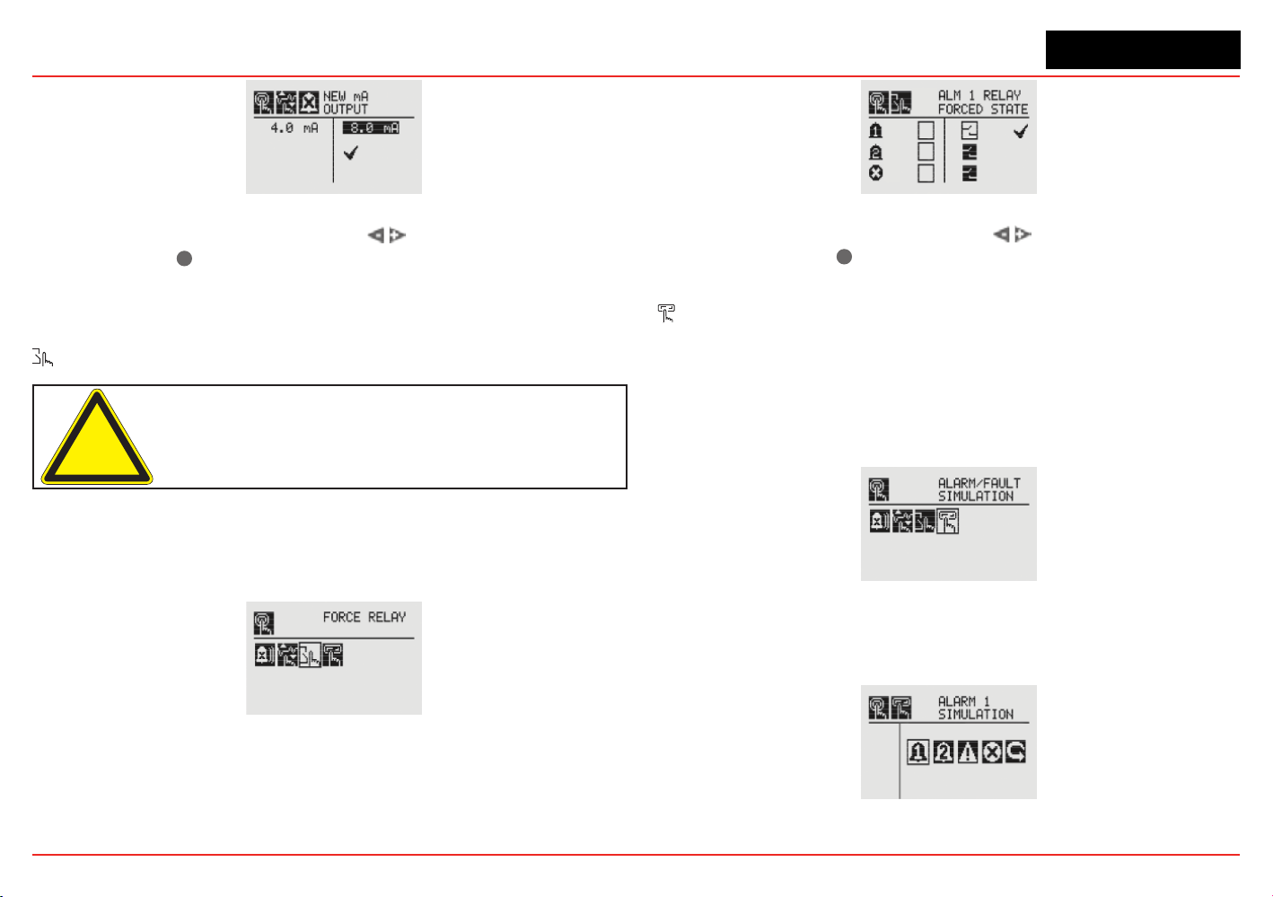
XNX Universal Transmitter
Section 2 - Installation and Operation
81
Figure 153. New mA Output Screen
Once the new value is input, use the switches to move to the
‘ü’ and use the
✓
magnetic switch on the front panel to set the
mA output.
Force Relays
Caution: Any relay conditions set in this menu will revert to the
normal operating values when exiting the Test Menu. For more
information on setting the relay options for normal operation, see
Relay Options.
The Force Relay menu allows peripheral devices driven by relays
from the transmitter to be tested. Depending on the relay options set
in the Relay Options menu (see Relay Options), the relay will be open
or closed.
Figure 154. Force Relays Screen
TheRelayStatescreenshowsthecurrentrelaycongurationin
the left column. The output can be controlled by changing the
value in the column on the right.
Figure 155. Relay State Screen
Once the new value is input, use the switches to move to
the ‘ü’ and use the
✓
magnetic switch on the front panel to
change the condition of the relay.
Alarm/Fault Simulation
Alarm and Fault simulation work in tandem with the previous
sections (Force mA Output and Force Relays) to allow thorough
testing of the XNX transmitter and the peripheral warning and
safety devices attached. Figure 156 shows the menu choices
for selecting an alarm or fault simulation.
Figure 156. Alarm/Fault Simulation Screen
Selectinganalarmleveltosimulateactivatesaconrmation
screen.
Figure 157. Alarm/Fault Simulation Menu

XNX Universal Transmitter
Section 2 - Installation and Operation
82
Figure 158. Conrmation
Selecting
✓
will simulate the alarm from the transmitter. If the
✖
is selected, the simulation will be aborted.
Figure 159. Warning and Fault Simulation Screens
To simulate a Warning or Fault from the transmitter, select the
appropriate icon from the menu.
Figure 160. Fault Simulation Conrmation
Aconrmationscreenwillappear.Select
✓
to simulate the
warning or fault from the transmitter. If the
✖
is selected, the
simulationwillbeaborted.UseAlarm/FaultResettoreset
alarms, faults, or warnings generated by the simulation.
Figure 161. Alarm/Fault Reset Screen
Aconrmationscreenwillappear.
Figure 162. Alarm/Fault Reset Screen
Select
✓
to reset the alarms, faults, or warnings generated by the
simulation. If the
✖
is selected, the simulation continues.
Caution: Relays and LEDs will return to their initial states after
simulations are completed unless faults and alarms are set to
latching by the user.
Warning: After changing parameters with a handheld device, verify
that the parameter settings are correct at the transmitter.
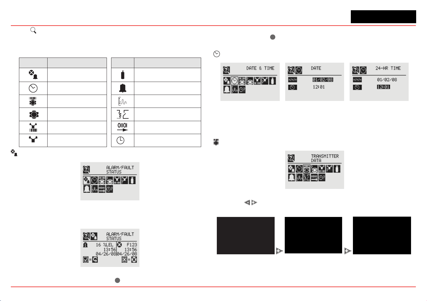
XNX Universal Transmitter
Section 2 - Installation and Operation
83
2.6.2
?
Information Menu
The Information Menu Displays the current status information for
these parmeters:
Symbol Description Symbol Description
Show Alarm/Fault Status Show Gas Data
Show Date/Time Show Range/Alarm Settings
Show Transmitter Data Show mA Level Settings
?
Show Transmitter Status Show Relay Settings
Show Sensor Data Show Fieldbus Settings
?
Show Sensor Status
?
Show Event History
Alarm/Fault Status
Figure 163. Alarm/Fault Status Screen
Select Alarm/FaultStatustodisplaytheAlarm/FaultStatus
screen allowing faults and alarms to be reset.
Figure 164. Alarm/Fault Status Screen
The ‘ü’ will be highlighted. Select
✓
to reset all faults and alarms
generatedbythetransmitterthenreturntotheAlarm/FaultStatus
screen. Select the
✖
switchtoreturntotheAlarm/FaultStatus
screen without resetting faults or alarms.
Date & Time
Figure 165. Date/Time Screens
The Date and Time screens display the date and time in the
formats currently set on the transmitter. To set the time and date
see Set Date & Time.
Transmitter Data
Figure 166. Transmitter Data Screen
Using the
switches, t
he Transmitter Data displays the ID, part
number,serialnumber,andversionnumberofthermware.
Figure 167. Transmitter ID, Part Number and Serial Number Screens

XNX Universal Transmitter
Section 2 - Installation and Operation
84
Figure 168. Transmitter Software, 4-20 Monitor and Option Version
TransmitterDataisalsousedtoupdatethecongurationofthe
XNX when an option board is added or changed. To add the new
option, use the
switches to navigate to the Option Revision
screen, then swipe the
✓
magnetic switch on the front panel to
display the Accept New Option Screen. The screen will show
the current option (if any) and the newly installed option. Use the
switches to highlight the option then swipe the
✓
magnetic
switch on the front panel to accept the change. The transmitter
will update the part number of the unit. The new option will then
be operational.
✓
✖
Figure 169. Updating The XNX for Option Boards Added or Changed
?
Transmitter Status
Figure 170. Transmitter Status Screen
Transmitter Status displays information about the XNX unit
including temperature, 4-20 mA output value, and supply
voltage.
Figure 171. Transmitter Temperature and Supply Voltage Screens
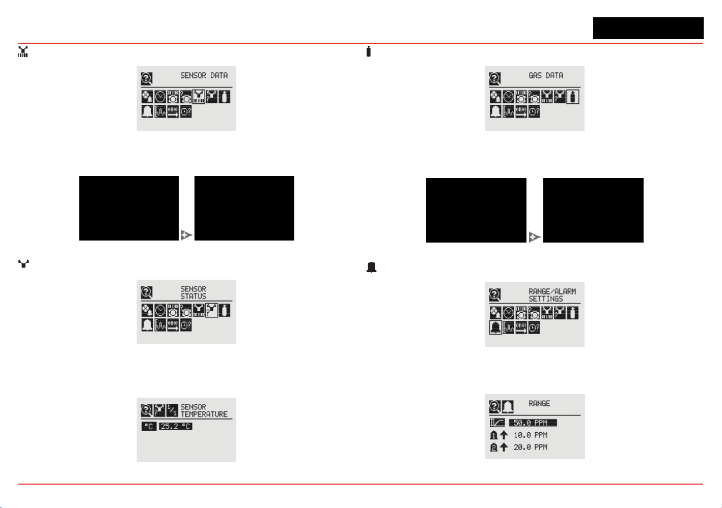
XNX Universal Transmitter
Section 2 - Installation and Operation
85
Sensor Data
Figure 172. Sensor Data Screen
Sensor Data displays information about the transmitter including
sensor type and sensor software revision.
Figure 173. Sensor Type and Software Screens
?
Sensor Status
Figure 174. Sensor Status Screen
Sensor Status displays the temperature of the sensor attached
to the transmitter. When equipped with an EC or mV sensor,
sensor life is also displayed.
Figure 175. Sensor Temperature Screen
Gas Data
Figure 176. Gas Settings Screen
GasDatadisplaysthecurrentdetectablegasasconguredfor
the attached sensor.
Figure 177. Gas Abbreviation and Full Scale Screens
Range/Alarm Settings
Figure 178. Range/Alarm Settings Screen
Range/AlarmSettingsdisplaysthecurrentlyconguredalarm
information.
Figure 179. Alarm Display Range Screen
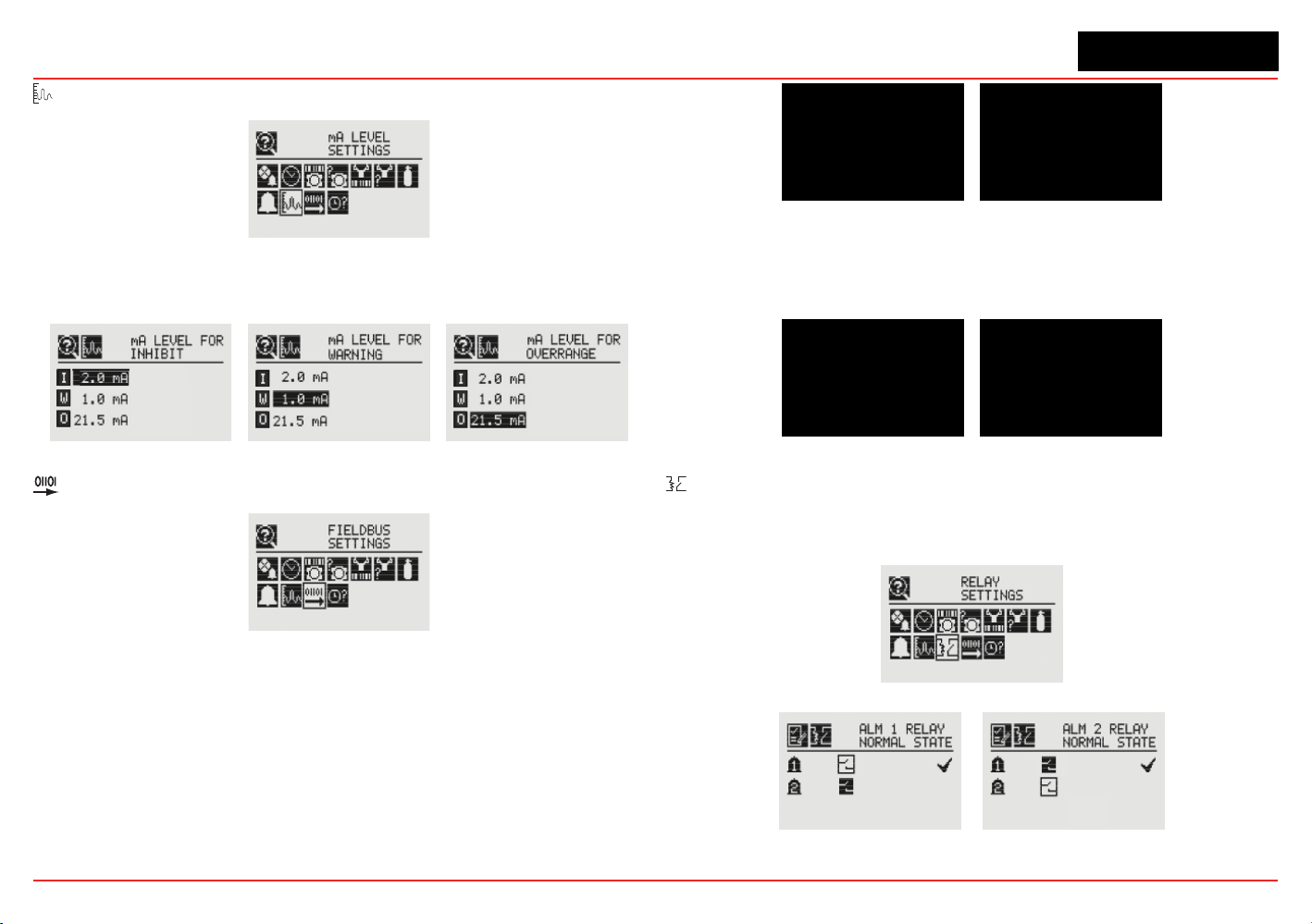
XNX Universal Transmitter
Section 2 - Installation and Operation
86
mA Level Settings
Figure 180. mA Level Settings Screen
mA Level Settings shows the current values for mA output for
Inhibit, Warning, and Overrange output.
Figure 181. mA Output Inhibit, Warning and Overrange Screens.
Fieldbus Settings
Figure 182. Fieldbus Settings
FieldbusSettingsdisplaysthecurrentcongurationofboth
HART and Modbus. To change the settings see Fieldbus
Options. HART displays the current HART address assigned to
the transmitter.
Figure 183. HART Configuration Settings
Modbus displays the current address and communication data
rate assigned to the transmitter.
Figure 184. Modbus Conguration Display Screen
Relay Data
The Relay Menu is enabled only if the XNX transmitter is
equipped with the optional relays.
Figure 185. Relay Data Screen
Figure 186. Relay State Screens
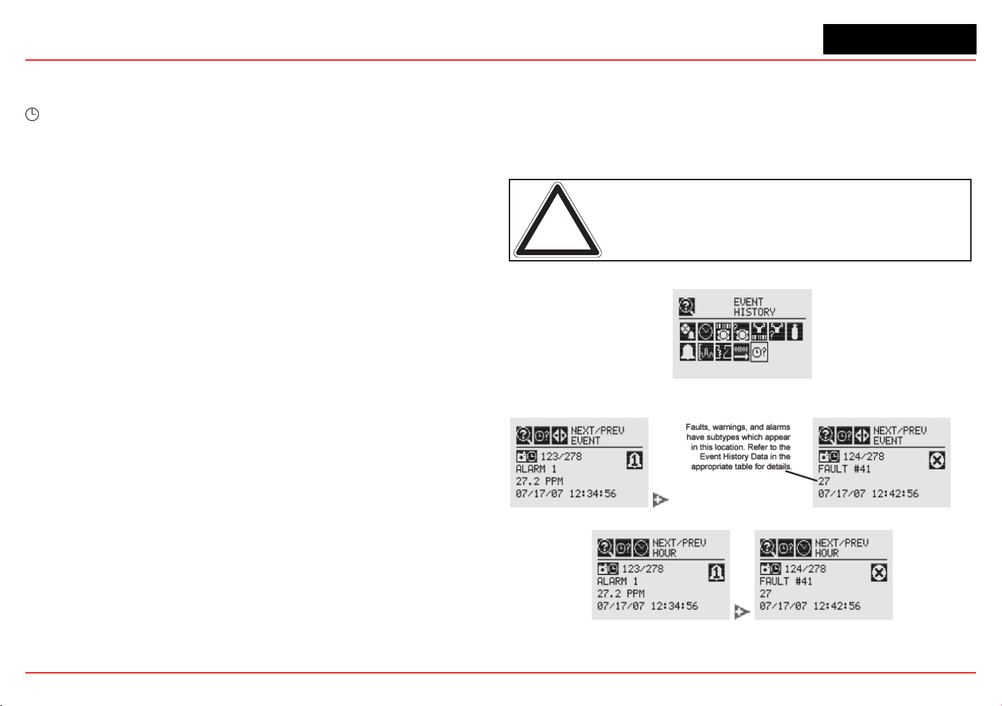
XNX Universal Transmitter
Section 2 - Installation and Operation
87
Relay Data displays the current setting of the optional relays on
the transmitter. To change the relay settings, see Relay Options.
?
Event History
The Event History screen lists all events that are activated by
the transmitter’s settings. Five types of events are recorded:
reset messages, alarm messages, warning messages, fault
messages, and informational messages. The events are listed in
chronological order beginning with the latest.
Eventscanbedisplayedthroughvebrowsingmodes:
• all events in order of occurrence
• all events by hour
• all events by day
• only the alarm events, in order of occurrence
• only the fault events, in order of occurrence
The Event History screen groups events into chronological order
(beginning from the unit’s installation). Events can also be viewed
by hour or by date.
Events listed in
hour
order are grouped without regard to date.
For example, all events that have occurred between noon and
1:00 o’clock since the transmitter’s installation can be isolated.
To view all events in hour order:
1. Usethemagneticwandtolterthedisplaybyhour.
2. Navigate through the displayed times.
Toisolatealloftheeventsfromaspecic
day
:
1. Usethemagneticwandtolterthedisplaybyday.
2. Navigate through the displayed days.
3. Filter the list by all events. This will display all events that
occurred on that day.
WhenthetransmitterisconguredwiththeSearchlineExcelor
Searchpoint Optima, the data reported in the event will be the
fault code from the Searchline Excel or Searchpoint Optima.
The transmitter records up to 1280 events in a circular buffer.
When event 1281 is recorded, the oldest event will be bumped
from the list.
Note: The leading zeros of faults and warnings are not displayed
in the event list; i.e., Fault 011 will be displayed as Fault 11.
Figure 187. Event History Screen
Figure 188. Chronological Event List
Figure 189. Chronological Event List by Hour
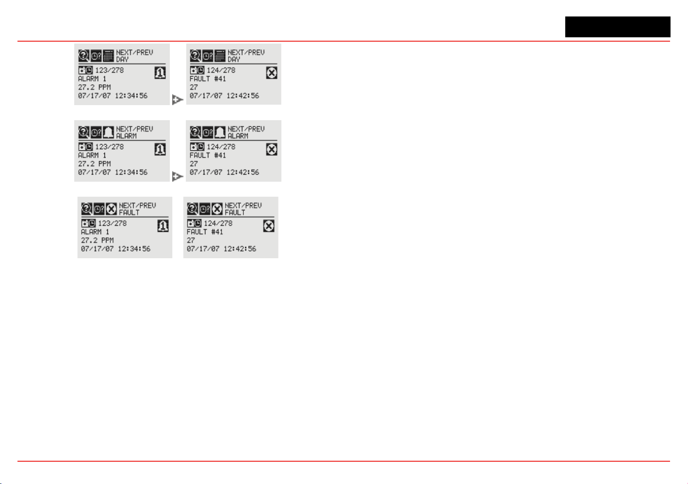
XNX Universal Transmitter
Section 2 - Installation and Operation
88
Figure 190. Chronological Event List by Day
Figure 191. Chronological Alarm List
Figure 192. Chronological Fault List
Thetransmitterisconguredwithvecable/conduitportsbuilt
into the housing for wiring and mounting sensors.

XNX Universal Transmitter
XNX Universal Transmitter Technical Manual
89
3 Calibration
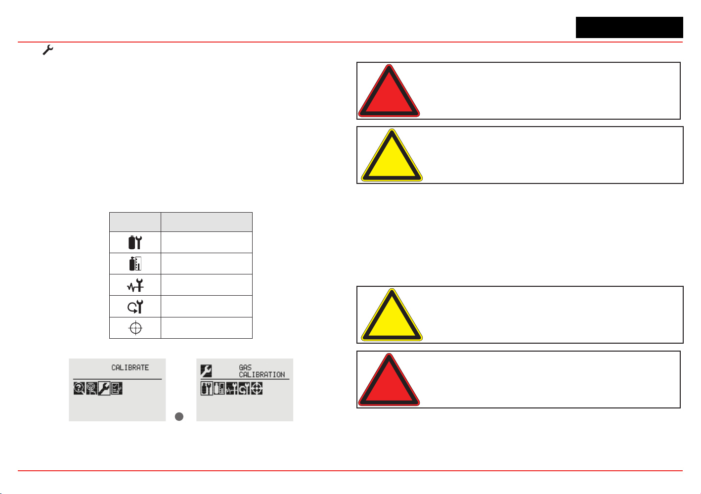
XNX Universal Transmitter
Section 3 - Calibration
90
3.1 Gas Calibration Menu
Each of the sensor technologies supported by the XNX
®
Universal Transmitter uses unique calibration procedures. The
description provided illustrates the XNX interface with the
sensor. The description does not replace the procedures found
in each sensor’s operating manual.
The Gas Calibration menu is used for Zero and Span calibration
as well as functional gas testing (bump test). The Gas
Calibration menu is accessed from the Main Menu.
This table shows the Gas Calibration menu icons:
Symbol Description
Gas Calibration
Bump Test
Calibrate mA Output
Soft Reset
Align Excel
✓
Figure 193. Gas Calibration Menu
3.2 Calibration
Warning: Do not use the XNX Universal Transmitter in oxygen-enriched
atmospheres. Concentrations displayed will be adversely affected by oxygen
depletion.
Caution: The calibration procedure should be performed only by qualified
personnel. Take appropriate precautions with cylinders of flammable and toxic
gases.
The default calibration values for the “Calibration Required”
diagnostic vary based on sensor type. This value can be
reprogrammed in accordance with site requirements to ensure
the highest level of safety. Correct operation of each sensor
should be conrmed before each use by calibration with a
certied test gas of known concentration before commissioning.
See Section 6 - Specications for calibration gas specications.
Caution: Recalibrate if the temperature of local environment has varied by more
than ±15°C from the temperature of calibration.
Warning: Honeywell recommends periodic bump tests (every 30 days or
in accordance with customer site procedures) to the sensor to insure proper
operation and compliance with the functional safety rating of the installation.
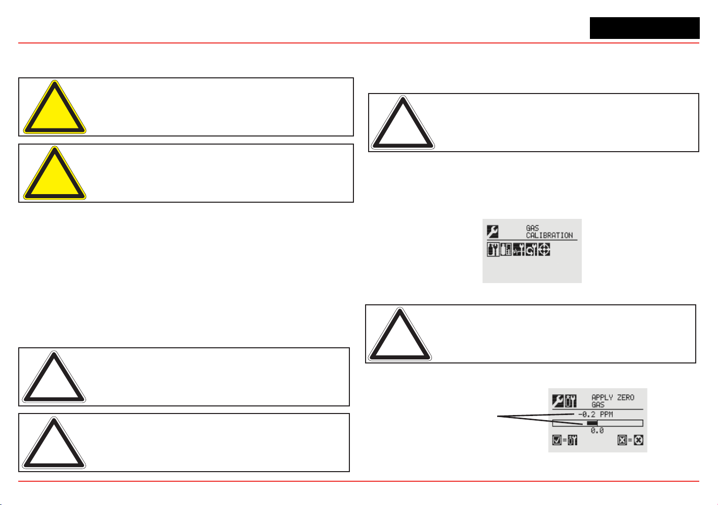
XNX Universal Transmitter
Section 3 - Calibration
91
3.2.1 Zero and Span Calibration for XNX EC Sensors,
mV Sensors, and Searchpoint Optima
Caution: Before initial calibration, allow the sensor to stabilize for 30 minutes
after applying power. When in Zero and Span Calibration modes, the current
output from the sensor is inhibited (default 2mA) to avoid false alarms.
Caution: For most sticky gases (e.g., HCl, Cl
2
) use PTFE tubing with short
pieces of rubber tube for the final connection (due to the inflexibility of PTFE). This
minimizes adhesion of the gas to the tube surface and allows more accurate
measurement.
To calibrate the sensor, use an appropriate span gas cylinder,
tubing, magnet, and calibration gas ow housing. Set the ow
regulator to 300-375 ml/min for XNX EC sensors or 500 ±200 ml/
min for XNX mV sensors. A compressed gas cylinder (20.9%Vol
oxygen) should be used to perform the zero calibration if the
area where the sensor is located contains any residual amount
of the target gas. If no residual gas is present, background air
can be used to perform the zero calibration. Contact a Honeywell
Analytics representative for details about suitable calibration kits.
To calibrate the sensor, follow the procedure in Section 3.2.2.
Note: The oxygen sensor does not require a zeroing procedure. Background
air (20.9%Vol oxygen) can be used to span the oxygen sensor in place of a
compressed air cylinder (20.9%Vol oxygen). See Section 6.3.2 for other sensors.
Note: EN performance standards require 10 minutes stabilization time for
application of zero and span gas for performance-approved EC, mV, and IR
sensors prior to calibration.
3.2.2 Calibration Procedure
This section outlines the steps for calibrating the transmitter’s
attached sensors.
Note: The Zero Calibration procedure should be performed prior to the Span
Calibration procedure.
1. If using a compressed gas cylinder, push the calibration
gas ow housing onto the bottom of the sensor and apply
the gas.
2. Access the Gas Calibration Menu.
Figure 194. Gas Calibration Menu
Note: The Gas Calibration menu is for both Zero Calibration and Span
Calibration.
Zero Calibration
Sensor Reading
at Current Settings
Figure 195. Zero Calibration Screen
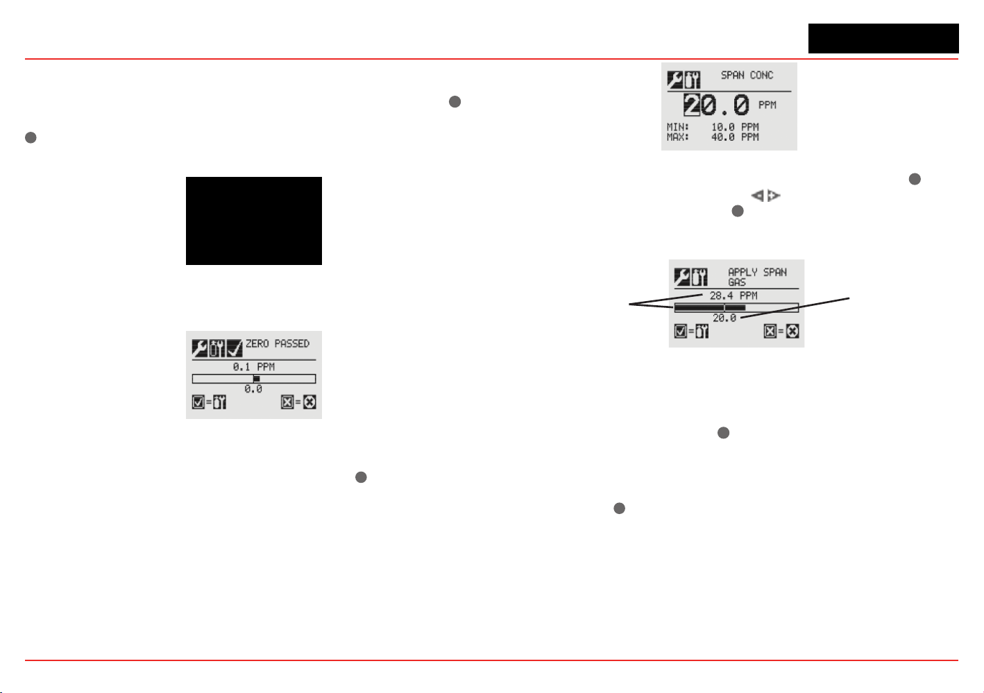
XNX Universal Transmitter
Section 3 - Calibration
92
As the sensor detects the gas and the concentration increases,
the values displayed will reect the changing concentration.
When the concentration values are stable, 3 minutes, select
✓
to
allow the transmitter to calculate the zero adjustment. Selecting
✖
will return to the Gas Calibration menu.
Figure 196. Zero Calibration in Progress
3. If the zero calibration is successful, the transmitter will
display the Zero Passed screen.
Figure 197. Zero Calibration Passed
Span Calibration
If a Span Calibration is not required, select the
✖
to skip the
Span Calibration and return to the Calibration menu.
4. When the Zero Calibration is complete, the Span
Concentration screen appears. The gas concentration
for the Span Gas Calibration can be changed. If the Span
Calibration is skipped, the Gas Calibration screen displays.
Figure 198. Span Gas Concentration Screen
5. Enter the concentration of the span gas by selecting
✓
to
choose the rst digit. Use the
switches to increment or
decrement the values. Use
✓
to accept the new value and
move to the next digit. Continue until all digits have been
selected.
Sensor Reading
at Current Settings
Calibration Gas
Concentration
Figure 199. Span Calibration Screen
6. Apply the span gas. As the sensor detects the gas and the
concentration increases, the values displayed will reect
the changing concentration. When the concentration
values are stable, select
✓
to perform the span. The Span
Calibration process also determines whether the sensor
is within the proper range to accurately detect the target
gas.
Selecting
✖
will cancel the span calibration and return to
the Gas Calibration menu.
7. When the sensor has completed the calibration and the
span algorithms have determined that it is within range,
the Span Passed screen will appear.
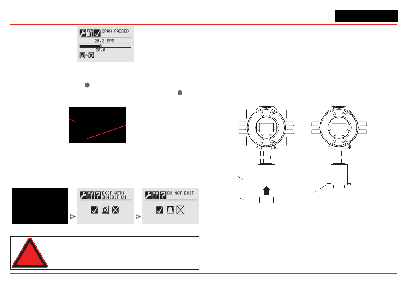
XNX Universal Transmitter
Section 3 - Calibration
93
Figure 200. Span Passed Screen
If the calibration is not successful, the Span Failed screen
will display. Selecting
✓
will return to the Span Concentration
screen to begin the span calibration again. Selecting
✖
will
exit Span Calibration and return to the Gas Calibration Menu.
Arrow indicates
gas values too low
Selecting ‘✔’ returns to
the Span Concentration
screen
Figure 201. Span Calibration Failed
Once the Zero Gas and Span calibrations are completed
successfully, the user will be prompted to:
• exit with inhibit off
• exit with inhibit on, or
• not exit.
Figure 202. Span Calibration Failed
Warning: When the XNX transmitter is placed in Inhibit Mode, alarms are
silenced. This will prevent an actual gas event from being reported. Inhibit Mode
must be limited to testing and maintenance only. Exit Inhibit Mode after testing
or maintenance activities.
3.2.3 Using the Calibration Cup
Refer to Figure 203 to attach the calibration cup:
1. Snap the calibration cup into the weather protector. The
two protrusions on the cup t into recesses in the weather
protector.
2. Attach the hose from the gas cylinder to the calibration cup.
Note that the cup’s ow is unidirectional. There is an arrow
on the bottom showing ow direction
3. Adjust the calibration ow rate
1
.
weather
protector
calibration cup
attach gas
cylinder hose
Figure 203. Attaching the Calibration Cup
1 300-375 ml/min for XNX EC sensors, 500 ±200 ml/min for XNX mV sensors, unless
otherwise directed
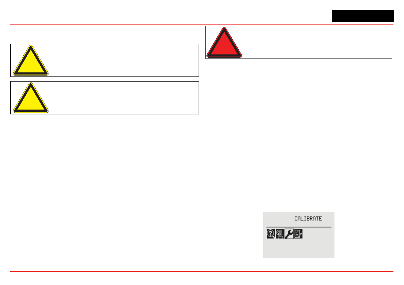
XNX Universal Transmitter
Section 3 - Calibration
94
3.2.4
Zero and Span Calibration of XNX EC Hydrogen
Sulde (H
2
S) Sensors
Caution: Before initial calibration, allow the sensor to stabilize for 30 minutes
after applying power. When in zero and span calibration modes, the current
output from the sensor is inhibited (default 2mA) to avoid false alarms.
Caution: Recalibrate if the temperature of local environment has varied by
more than ±15°C from the temperature of calibration.
Hydrogen Sulde sensors can be affected by extreme humidity
changes. A sudden increase in ambient humidity can result in a
short-term positive drift in the instrument’s reading. A sudden
decrease in ambient humidity can result in a short-term negative
drift in the instrument’s reading. These are most likely to be
noticed during calibration with dry or cylinder gas.
When calibrating hydrogen sulde cartridges, the following
should be taken into account while following the procedure in
Section 3.2.2.
1. To zero the sensor, use a compressed gas cylinder of
20.9%Vol oxygen (not nitrogen). Do not use background
air.
If a span calibration is to be performed, the span calibration gas
should be applied to the sensor immediately after the zeroing
procedure. Do not allow the sensor to return to ambient air
conditions.
Warning: Long-term exposure (> 20 minutes) to concentrations exceediing the
full-scale range of the sensor can cause it to lose sensitivity. The ouput of the
sensor may then decrease in value even though high levels of toxic gas are still
present. Before re-calibrating the transmitter, verify the absence of gas.
3.2.5 705/705HT Calibrating
For complete calibration and conguration information, see the
Type 705 Operating Instructions (P/N: 00705M5002).
3.2.6 Sensepoint/Sensepoint HT Calibrating
For complete calibration and conguration information, see the
Sieger Sensepoint Technical Handbook (P/N: 2106M0502).
3.2.7 Calibrating the Searchpoint Optima Plus
Complete calibration and conguration information can be
found in the Searchpoint Optima Plus Operating Instructions
(P/N:2108M0501). If properly installed and maintained, the
Searchpoint Optima Plus sensor will not require routine
calibration. This is due to the inherent stability of the IR
absorption process and the unit’s fully compensated optical
conguration.
1. From the Calibration menu, select the Gas Calibration option.
Figure 204. Calibration menu
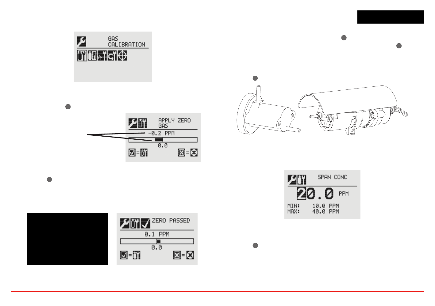
XNX Universal Transmitter
Section 3 - Calibration
95
z
Figure 205. Gas Calibration menu
2. Perform a zero calibration. When concentration values are
stable, select
✓
✓for XNX to calculate the zero adjustment
Sensor Reading
at Current Settings
Figure 206. Apply Zero Gas screen
3. Select ✓
✖
to return to the Gas Calibration menu. If the zero
calibration was successful, the transmitter will display the
Zero Passed screen
Figure 207. Zero Calibration screens
4. Begin the span calibration by entering the concentration
value of the calibration gas: Select
✓
✓ to choose the rst
digit. Use +/- to increment/decrement values. Select
✓
✓ to
accept the value and move to the next digit. Use calibration
cover P/N 2108B0272 to perform span calibration at a ow
regulator of 1 LPM. (If a span calibration is not required,
select
✖
to return to the calibration menu.)
Figure 208. Searchpoint Optima Plus
5. Continue until all three digits have been entered.
Figure 209. Span Concentration screen
6. Apply the span gas. When concentration values are stable,
select
✓
✓ to calculate the span adjustment. This process
also determines if the sensor is within range to accurately
detect the target gas.
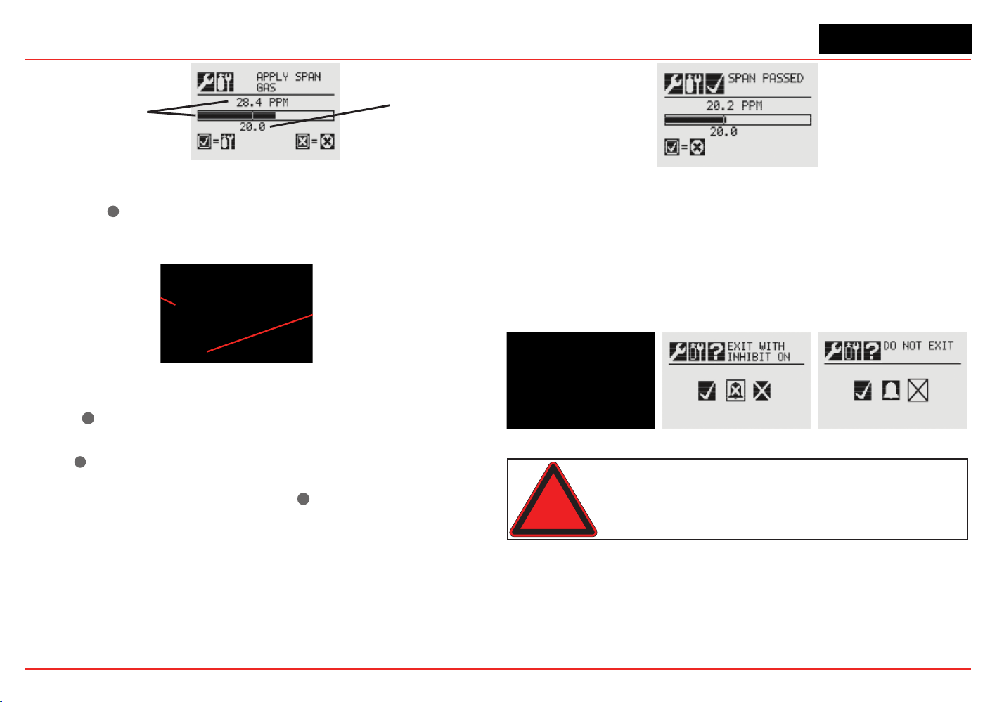
XNX Universal Transmitter
Section 3 - Calibration
96
Sensor Reading
at Current Settings
Calibration Gas
Concentration
Figure 210. Span adjustment calculation
7. Select ✓
✖
to return to the Gas Calibration menu. If the
calibration is not successful, the Span Failed screen will be
displayed.
Arrow indicates
gas values too low
Selecting ‘✔’ returns to
the Span Concentration
screen
Figure 211. Span Failed screen
Select ✓
✓
to return to the Span Concentration screen to repeat
the span calibration.
Select
✖
to exit Span Calibration and return to main
Calibrate screen. If Span Calibration is exited, the previous
calibration values will be used. Select
✓
✓ to return to the Span
Concentration screen.
If the calibration is successful, the Span Passed screen will be
displayed.
Figure 212. Span Passed screen
8. Exit the Calibration Menu. After the zero and span
calibrations have been successfully completed, the user will
be prompted to:
• Exit and turn alarm and fault inhibit off,
• Exit and leave the transmitter in inhibit mode. or
• Not exit
Figure 213. Calibration exit options
Warning: When the XNX transmitter is placed in Inhibit Mode, alarms are
silenced. This will prevent an actual gas event from being reported. Inhibit Mode
must be limited to testing and maintenance only. Exit Inhibit Mode after testing
or maintenance activities.
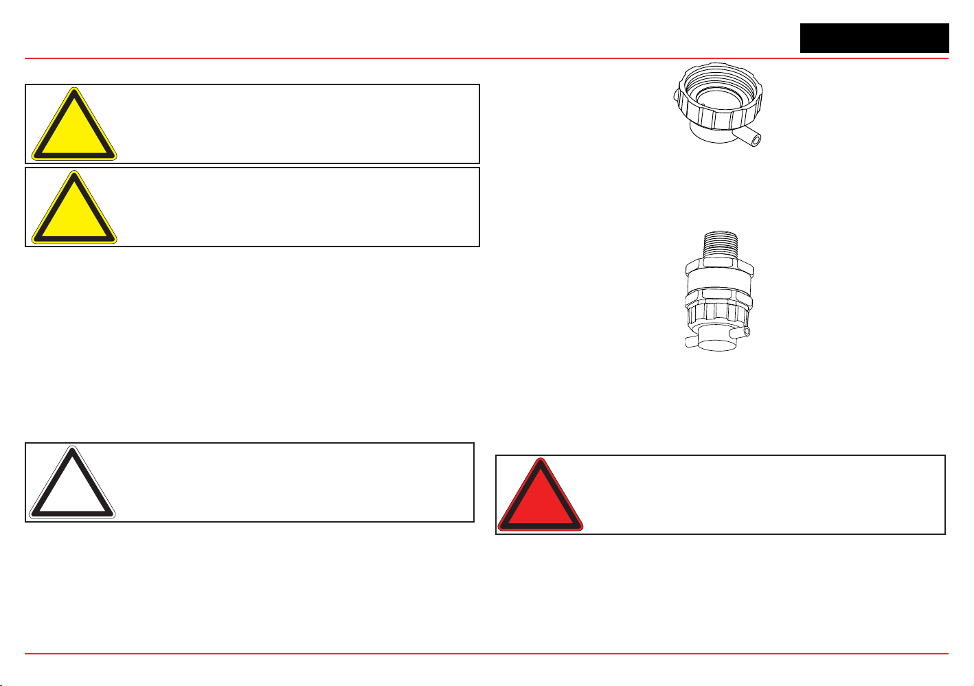
XNX Universal Transmitter
Section 3 - Calibration
97
3.2.8
Zero and Span Calibration for MPD Sensors
Caution: Extended or frequent exposure to elevated concentrations
of combustible gases may affect sensor sensitivity. Verify sensor
performance by frequent calibration.
Caution: Before initial calibration allow the sensor to stabilize for 30 minutes
after applying power. When in zero and span calibration modes, the current
output from the sensor is inhibited (default 2mA) to avoid false alarms.
The Gas Calibration menu is for both zero and span calibrations.
This section describes how to calibrate MPD ammable sensors
tted to the transmitter. The calibration adjustments are made on
the transmitters display. Gassing is performed at the sensor,
which may be locally or remotely located.
The following equipment is required:
• Flow housing (P/N: 1226A0411)
• Test gas
• Regulator
Note: Zero gas and Span gas should be at about the same humidity levels to
avoid erroneous cell responses.
1. At the MPD, remove the weatherproof cap, if equipped.
2. Fit the ow housing onto the MPD.
Figure 214. Flow Housing
3. Reverse the cap removal procedure. Figure 215 shows the
ow housing accessory tted to the MPD.
Figure 215. MPD with Flow Housing
4. Connect the ow housing (using either gas pipe) to the
regulated cylinder containing a known concentration of the
target gas at approximately the sensor alarm point, e.g., 50%
LEL methane in air.
Warning: As some test gases are hazardous, exhaust the flow housing outlet
to a safe area.
5. Follow the procedure in Section 3.2.1 for both zero and
span calibrations.
6. Apply the target gas to the sensor. Pass the gas through
the ow housing at a rate of
300-375 ml/min for XNX EC
sensors or 500 ±200 ml/min for XNX mV sensors
.
XNX Universal Transmitter
Section 3 - Calibration
98
Sensors should be calibrated at concentrations
representative of those to be measured. It is always
recommended that the sensor be calibrated with the target
gas it is to detect.
Caution: Responsibility for identifying and recording a sensor calibration
made with a different gas rests with the user. Refer to local regulations where
appropriate.
Ensure that the sensor and the vicinity around it is clear of
all traces of the calibration gas before continuing. This is to
avoid triggering spurious alarms.
If calibration fails at any point, discard the cartridge and
replace it with a new one (see Section 4.1) .
7. Remove the test equipment, ret the weatherproof cap to
the sensor (if previously removed for the test), and return
the system to normal operation.
3.2.9 MPD Flammable Sensor Operational Life
The pellistors used in ammable gas sensors can suffer
from a loss of sensitivity when in the presence of poisons or
inhibitors, e.g., silicones, suldes, chlorine, lead, or halogenated
hydrocarbons. The pellistors are poison resistant to maximize the
operational life of the ammable sensor. The typical operating life
of the pellistor sensor used in the MPD-CB1 is 60 months.
3.2.10 XNX EC Sensor Operational Life
The typical life of a toxic gas sensor dependst on the application,
frequency, and amount of gas exposure. Under normal conditions
(3 month visual inspection and 6 month test/recalibration) the toxic
sensor has an expected life equal to or greater than these lifetimes:
• 12 months for ammonia, hydrogen chloride, and hydrogen
uoride sensors (see further ammonia information below).
• 24 months for chlorine dioxide, oxygen, and other toxic
sensors.
See Section 4 - Maintenance for sensor replacement procedures.
Caution: Oxygen deficient atmospheres (less than 6%V/V) may result in
inaccurate readings and performance.
Ammonia electrochemical cells are reliable and suitable for
applications where no background concentration of ammonia exists.
Under these conditions the cells are expected to operate for 12 to 24
months.
These ammonia cells are of the consumptive type. Their operating
life can be adversely affected by continuous or excessive exposure
to ammonia, or by prolonged exposure to high temperatures and
moisture.
To ensure continued detection availability, bump test the sensors
regularly and implement an appropriate cell replacement program.
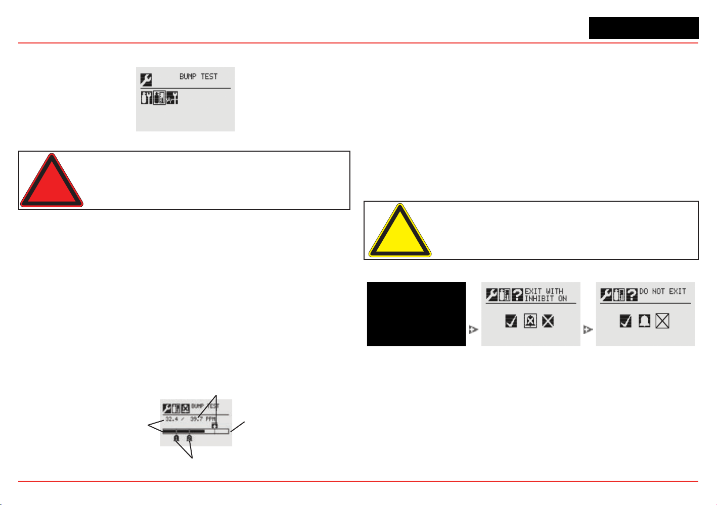
XNX Universal Transmitter
Section 3 - Calibration
99
3.3 Functional Gas Testing (Bump Testing)
Figure 216. Bump Test Menu
Warning: Exposure to desensitizing or contaminating substances or
concentrations causing operation of any alarm may affect sensor sensitivity.
Following such events, it is recommended to verify sensor performance by
performing a functional gas test (bump test).
It is recommended that the sensor be tested frequently to ensure
that the system is operating properly. Different sensor types may
require more frequent maintenance, depending on the
environmental conditions and the gases present. The
weatherproof cover has a spigot for attaching tubing from a gas
cylinder. This may be used for a simple functional (bump) test of
the sensor. However, environmental conditions may make this
unsuitable for some gas typesor applications. It is the
responsibility of the user to ensure suitability of this method for
each application.
1. When bump gas is applied to the sensor, the bump test
screen displays the current reading of the sensor and the
peak reading that occurred during the bump test.
Peak Reading
Full Scale
Alarm Levels
Current Sensor
Reading
Figure 217. Bump Test Screen
2. If the difference between the reading and the applied
gas concentration is outside the acceptable limits for the
application, follow the procedures for zeroing and calibrating
the sensor (see Section 3.2.1).
3. If the reading is still inaccurate, replace the sensor (see
Section 4.1).
Once the bump test is completed successfully, the transmitter
will exit the calibration procedure. Before returning to the Gas
Calibration menu, the user will be prompted to exit and turn
alarm and fault inhibit off, exit and leave the transmitter in inhibit
mode, or not exit.
Caution: Exiting before the gas level has fallen below the level of Alarm 1 will
cause the transmitter to go into alarm.
Figure 218. Exiting the calibration procedure
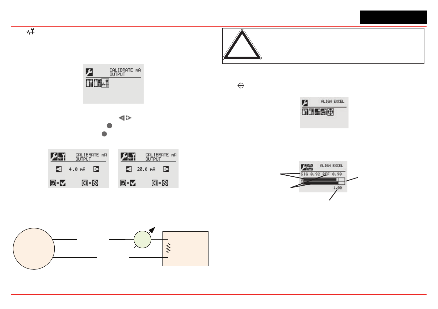
XNX Universal Transmitter
Section 3 - Calibration
100
3.4 Calibrate mA Output
Use Calibrate mA Output to adjust the milliamp output to provide
the correct output levels at peripheral devices connected to the
transmitter.
Figure 219. Calibrate mA Output Menu
To adjust the 4mA output, use the
switches to increase or
decrease the output, then use
✓
to accept the new value and
move to the 20mA setting or
✖
to discard the selection and
return to the previous menu.
Figure 220. Calibrate mA Output Screens
During installation, an mA meter must be connected in series
with the 4-20 mA loop as shown below.
Control Equipment
XNX
mA
Meter
4-20 mA loop
4-20 mA loop
Remote end
R load
Figure 221. 4-20 mA loop with mA meter
Note: Calibrated mA output is required for proper operation of internal
diagnostics.
An F165 fault will be reported if the 4-20 mA calibration fails.
3.5 Align Excel (Searchline Excel)
Figure 222. Align Excel Menu
For detailed information on Aligning the Searchline Excel, see the
Searchline Excel Technical Manual (P/N: H-MAN0530-V1).
Alignment Bargraph
Signal Strength
1.00 Signal Strength Target
Reference Value
Figure 223. Align Excel Screen
Align the unit using the information found in the Searchline Excel
manual. As the alignment is performed, the transmitter display will
indicate the signal strength in the form of a bar graph. Align the
Excel until the signal strength bar graph reaches or exceeds 1.00 as
shown on the display.
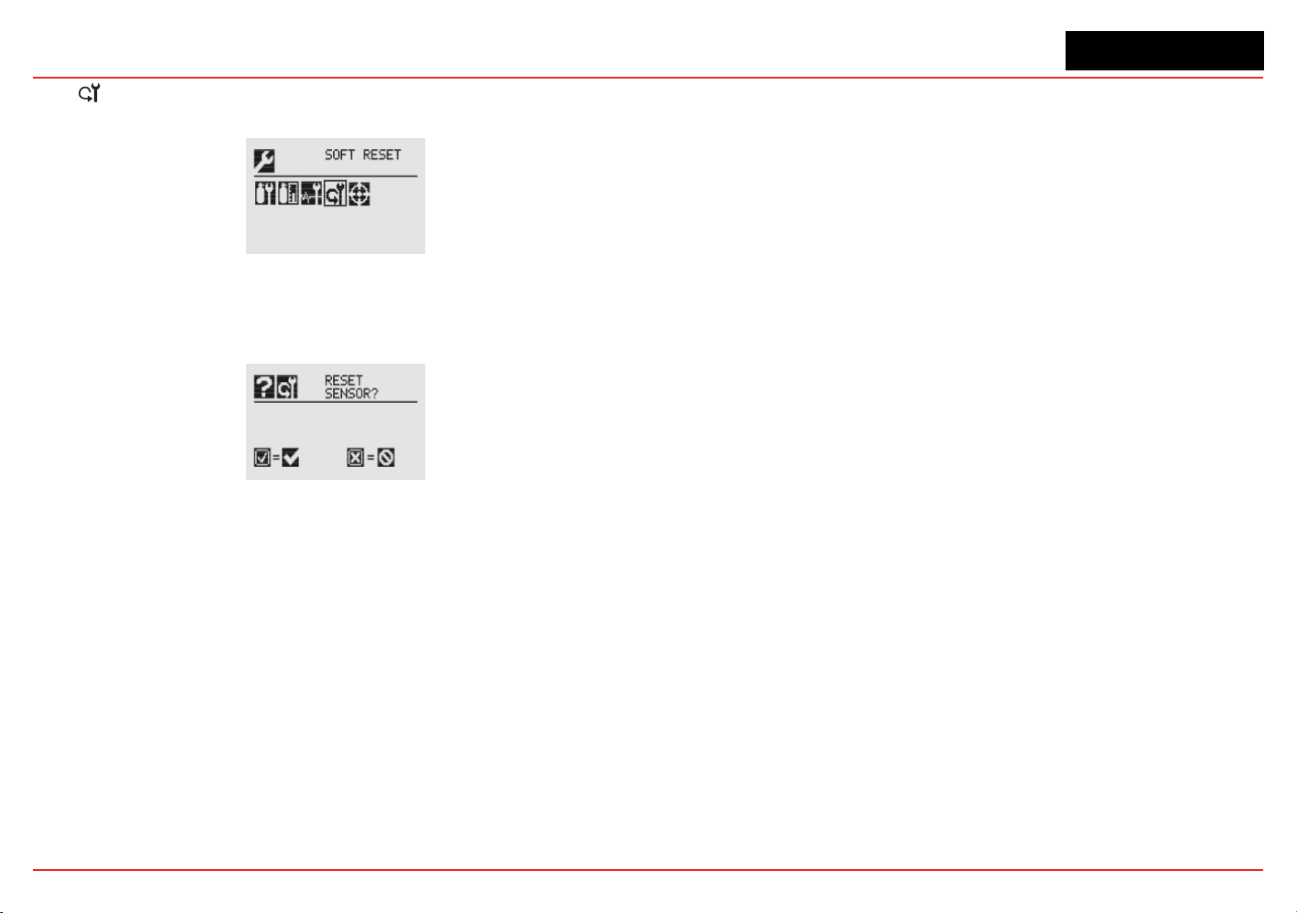
XNX Universal Transmitter
Section 3 - Calibration
101
3.6 Soft Reset
(Searchline Excel and Searchpoint Optima Plus only)
Figure 224. Soft Reset Menu
For transmitters connected to a Searchline Excel or Searchpoint
Optima Plus sensor, the Soft Reset sends these infrared devices
a signal to restart the sensor.
Figure 225. Soft Reset Sensor Screen

XNX Universal Transmitter
Section 3 - Calibration
102

XNX Universal Transmitter
XNX Universal Transmitter Technical Manual
103
4 Maintenance
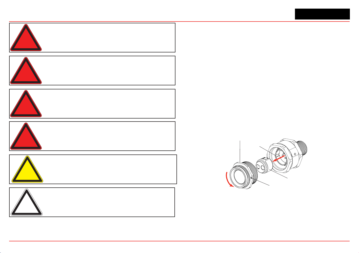
XNX Universal Transmitter
Section 4 - Maintenance
104
Warning: When servicing or replacing sensors, reduce the risk of ignition
of hazardous atmosphere by declassifying the area or disconnecting the
equipment from the supply circuit before opening the sensor enclosure.
Keep the assembly tightly closed during operation.
Warning: Take care when handling sensors as they may contain corrosive
solutions. Do not tamper or in any way disassemble the sensor cell. Do not
expose to temperatures outside the recommended range. Do not expose
the sensor to organic solvents or ammable liquids.
Warning: At the end of their working lives, sensors must be disposed of in an
environmentally safe manner, in accordance with local waste management
requirements and environmental legislation. Sensors should NOT be
incinerated as they may emit toxic fumes.
Warning: Verify all outputs, including display, after installation, after service
events, and periodically to ensure the safety and integrity of the system.
Caution: The following procedure should be followed carefully and
performed only by suitably trained personnel. A fault condition will be
signaled by the sensor if it is removed with the unit under power.
Note: If the power-on self-test was skipped during maintenance activities,
restart the transmitter.
4.1 MPD Sensor Cartridge Replacement
Using Figure 226 as a guide, follow this procedure:
1. Verify that the label on the new sensor is the correct gas
type.
2. Remove power from the transmitter.
3. Unscrew the weatherproof cover (if equipped), loosen the
retainer locking screw, and unscrew the sensor retainer.
4. Remove the old sensor by pulling without twisting.
5. Slide the replacement cell into the MPD body taking care
to align the tab with the alignment slot, then press the cell
rmly to seat it into the body.
6. Ret the sensor retainer, tighten the locking screw and ret
the weatherproof cover (if equipped).
7. Recalibrate the sensor following the procedures in Section
3.2.2.
Cell Alignment Slot
Sensor Cell
IR or Cat Bead
Sensor Retainer
and Locking Screw
Internal O-ring
(critical to performance times)
Figure 226. Removing the Plug-in Sensor
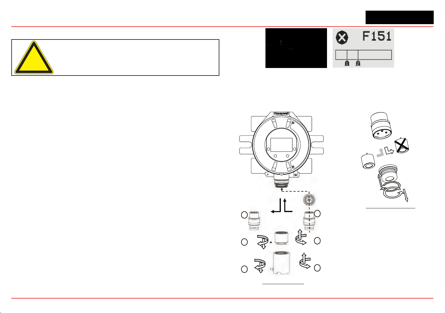
XNX Universal Transmitter
Section 4 - Maintenance
105
4.2 XNX
®
EC Sensor Cartridge Replacement
Caution: For toxic sensors, remove the shorting clip from the bottom of the
sensor prior to installation. No shorting clip is provided with oxygen sensors.
The serviceable sensor allows replacement of the cell inside
the sensor. The sensor cell can be replaced with a cell of the
same type or changed to detect a different target gas. Both
procedures follow.
When replacing oxygen (O
2
) sensor cells, the initial warm-up time
is between 10 and 15 minutes. This warm-up is required only
after sensor cell replacement.
4.2.1 Replacing with the Same Cartridge Type
To replace the cell follow this procedure:
1. Unscrew the weatherproof cover, loosen the sensor
retainer locking screw, and unscrew the sensor retainer.
2. Remove the old sensor by pulling without twisting.
3. Unscrew the sensor cap.
4. Remove the old cell by pulling without twisting.
5. Verify that the new cell is the same type as the old one.
6. Plug the new cell into the sensor, taking care to align the
sensor pins with the connector holes in the PCB.
7. Ret the sensor retainer, tighten the locking screw, and
ret the weatherproof cover.
8. Sensor warm-up will begin and the XNX display will
alternate between two screens: “Fault 151” and “WARM.”
Figure 227. Sensor screens during warmup
9. Follow the procedure to accept the new sensor in Accept
New Sensor Type.
10. Recalibrate the sensor following the procedures in Section 3.2.1.
Transmitter
Sensor Retainer &
Locking Screw
Old Sensor
3
2
1
4
5
6
New Sensor
EC Sensor Removal
Sensor Cap
Old cell
New cell
Sensor Cell Replacement
Figure 228. XNX EC Sensor Cell Replacement
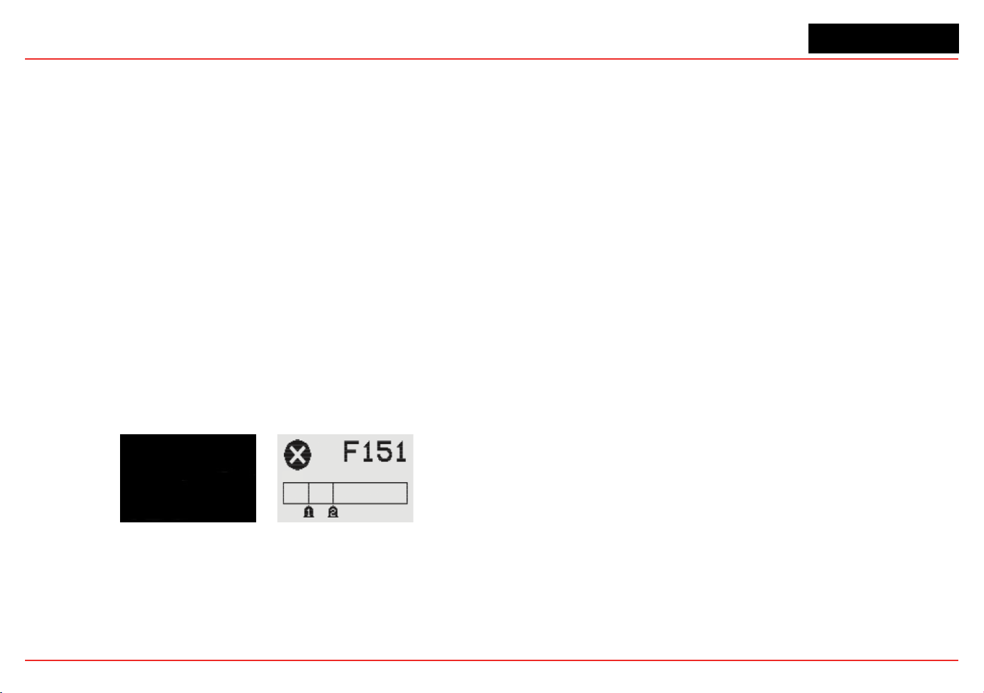
XNX Universal Transmitter
Section 4 - Maintenance
106
4.2.2 Replacing with a Different Cartridge Type
To replace the cell with a cell for a different gas, follow this
procedure:
1. Unscrew the weatherproof cover, loosen the sensor
retainer locking screw, and unscrew the sensor retainer.
2. Remove the old sensor by pulling without twisting.
3. Unscrew the sensor cap.
4. Remove the old cell by pulling without twisting.
5. Plug the new cell into the sensor, taking care to align the
sensor pins with the connector holes in the PCB.
6. Ret the sensor, taking care to align the sensor pins with
the connector.
7. Ret the sensor retainer, tighten the locking screw, and
ret the weatherproof cover.
8. The transmitter will enter sensor warm-up mode. However,
due to the change in sensor cell type, the transmitter
will not enter monitor mode until the unit has been
recongured. The display will show the sensor warm-up
screen:
Figure 229. Sensor screens during warmup
Note the message “G:TBV:O2”. “TBV” indicates that the
operator must recongure the transmitter to recognize
the new sensor cell. “O2” will reect the target gas of the
new cell, i.e., H2S, NO2, etc. The display will also alternate
the warm-up screen with the Fault 151 screen. This
indicates that the communication between the transmitter
and the original cell is no longer recognized. This fault
condition will clear after the transmitter has been properly
recongured.
The reconguration of the XNX for a new cell/target gas is
achieved through Accept New Sensor Type. Recalibrate
the sensor following the procedures in Section 3.2.2.
4.2 XNX EC Sensor Cartridge Replacement

XNX Universal Transmitter
XNX Universal Transmitter Technical Manual
107
5 Warnings and Faults

XNX Universal Transmitter
Section 5 - Warnings/Faults
108
5.1 Warning Messages
Warning Description
Applicable
Sensors
Latching / Non-Latching
Frequency of Diag-
nostic
Event History Data Action For Resolution
W001
XNX
®
24 VDC
Supply Bad
All Non-latching 2 seconds
XNX supply
voltage x1000
Check wire of 24V power supply to XNX as well as power supply opera-
tion.
W002
XNX Tempera-
ture Error
All Non-latching 2 seconds
XNX tempera-
ture (Celsius)
Check location for heat sources. Fit with sunshade or other protection.
Change location of XNX. Check temperature in Info->Transmitter Status
to ensure temperature is being measured properly.
W003
Simulated
Warning/Fault
All Non-latching Enabled by user 0 Performing an alarm/fault reset will clear all simulation.
W005
Sensor Tem-
perature Error
Optima Non-latching
XNX polls sensor
every 2 seconds,
diagnostic fre-
quency controlled
by sensor
Sensor fault or
warning code
(Note 4)
Check location for heat sources. Fit with sunshade or other protection.
Change location of XNX. Check temperature in Info->Sensor Status to
ensure temperature is being measured properly.
Sensor Tem-
perature Error
Excel Non-latching
XNX polls sensor
every 2 seconds,
diagnostic fre-
quency controlled
by sensor
Sensor fault or
warning code
(Note 4)
Check location for heat sources. Fit with sunshade or other protection.
Change location of XNX. Check temperature in Info->Sensor Status to
ensure temperature is being measured properly.
Sensor Tem-
perature Error
ECC Non-latching 2 seconds
Sensor temper-
ature (Celsius)
Check location for heat sources. Fit with sunshade or other protection.
Change location of XNX. Check temperature in Info->Sensor Status to
ensure temperature is being measured properly.
W006
Negative Drift ECC, mV Non-latching 2 seconds
Raw gas con-
centration of
sensor
Check sensor location for external interference. Perform zero calibra-
tion. If problem persists after zero calibration and no interference exists,
replace sensor.
Negative Drift
Optima,
Excel
Non-latching
XNX polls sensor
every 2 seconds,
diagnostic fre-
quency controlled
by sensor
Sensor fault or
warning code
Check sensor location for external interference. Perform zero calibra-
tion. If problem persists after zero calibration and no interference exists,
replace sensor.
W007
Calibration
Required
All Non-latching 2 seconds
Number of days
remaining until
calibration ex-
pires, negative
= number of
days expired
Time since the last span calibration has exceeded a dened limit. Per
-
forming a successful span calibration will clear the condition. The limit is
the user-dened calibration interval. W007 can be disabled by setting the
calibration interval to 0.

XNX Universal Transmitter
Section 5 - Warnings/Faults
109
Warning Description
Applicable
Sensors
Latching / Non-Latching
Frequency of Diag-
nostic
Event History Data Action For Resolution
W009
Sensor 24 VDC
Supply Bad
Optima,
Excel
Non-latching
XNX polls sensor
every 2 seconds,
diagnostic fre-
quency controlled
by sensor
Sensor fault or
warning code
(Note 4)
Check wire of 24V power supply to XNX as well as power supply opera-
tion. Also check wiring between XNX and Optima/Excel.
W010
Sensor Path
Obscured
Optima Non-latching
XNX polls sensor
every 2 seconds,
diagnostic fre-
quency controlled
by sensor
Sensor fault or
warning code
(Note 4)
Check location for external interference. Check sensor for dirty windows.
Beam Block Excel Non-latching
XNX polls sensor
every 2 seconds,
diagnostic fre-
quency controlled
by sensor
Sensor fault or
warning code
(Note 4)
Check location for external interference or obstructions in the IR path.
Check sensor for dirty windows. Check Excel alignment.
W011
Sensor In-
ternal Lamp
Issue
Optima Latching
XNX polls sensor
every 2 seconds,
diagnostic fre-
quency controlled
by sensor
Sensor fault or
warning code
(Note 4)
Remove and return to Honeywell for repair.
W012
Excessive
Float
Optima,
Excel
Non-latching
XNX polls sensor
every 2 seconds,
diagnostic fre-
quency controlled
by sensor
Sensor fault or
warning code
(Note 4)
Check sensor location for external interference, check sensor for opera-
tion and re-zero where appropriate.
W013
Sensor Loop
Failure, (Sen-
sor is losing/
has lost mA
output signal.
These are
detected by
Optima and
Excel.
Optima,
Excel
Latching
XNX polls sensor
every 2 seconds,
diagnostic fre-
quency controlled
by sensor
Sensor fault or
warning code
(Note 4)
Check that supply voltage is stable. Check wiring between Optima/
Excel and XNX. Check loop impedance of wiring. Check that switches
S3 and S4 are set correctly. If the switch settings need to be changed,
power down the transmitter before changing the switch settings. Once
the problem has been resolved, a Soft Reset must be performed for the
Calibration menu to clear W013.
W014
Sensor Real
Time Clock
issue
Excel Non-latching
XNX polls sensor
every 2 seconds,
diagnostic con-
trolled by sensor
Sensor fault or
warning code
(Note 4)
Reset “date and time” in Excel, re-cycle Excel power and conrm “date
and time.” If not retained, remove and return to Honeywell for repair.

XNX Universal Transmitter
Section 5 - Warnings/Faults
110
Warning Description
Applicable
Sensors
Latching / Non-Latching
Frequency of Diag-
nostic
Event History Data Action For Resolution
W015
Sensor Inter-
nal Failure
Optima,
Excel
Latching and Non-
latching
XNX polls sensor
every 2 seconds,
diagnostic fre-
quency controlled
by sensor
Sensor fault or
warning code
(Note 4)
Remove and return to Honeywell for repair.
Sensor has an
internal soft-
ware error
Excel Latching
XNX polls sensor
every 2 seconds,
diagnostic fre-
quency controlled
by sensor
Sensor fault or
warning code
(Note 4)
Cycle Excel power and conrm “fault cleared.” If not, replace sensor.
W016
Sensor Instal-
lation Not
Complete
Excel Non-latching
XNX polls sensor
every 2 seconds,
diagnostic fre-
quency controlled
by sensor
Sensor fault or
warning code
(Note 4)
Check Excel alignment. Perform a zero calibration.
W018
General Diag-
nostics
Optima,
Excel
Non-latching
XNX polls sensor
every 2 seconds,
diagnostic fre-
quency controlled
by sensor
Sensor fault or
warning code
(Note 4)
Check sensor connections, check sensor operation, t replacement sen-
sor, replace personalty board.
W019
Sensor Inter-
nal 5V Power
Supply Defect
Excel Non-latching
XNX polls sensor
every 2 seconds,
diagnostic fre-
quency controlled
by sensor
Sensor fault or
warning code
(Note 4)
Remove and return to Honeywell for repair.
W020
Forced mA
Timeout
All Latching 1 second Forced mA
Indicates that a forced mA condition was left on for more than 15
minutes. No action required as mA operation will be returned to normal
automatically.
W021
Forced Relay
Timeout
All Latching 1 second
Forced
relay status,
1=Alarm1 on,
2=Alarm2 on,
4=Fault on
Indicates that a forced relay condition was left on for more than 15
minutes. No action required as relay operation will be returned to normal
automatically.
W022
mV Sensor
Calibration
Needed
mV Latching
When user
changes sensor
type or gas
1=new sensor,
2=changed
personality,
3=changed gas
Generated after accepting a new mV sensor or changing the mV sensor
type or changing the mV gas selection. This is a warning to user that a
span calibration should be performed. If a span calibration is not per-
formed, the default calibration values will be used.

XNX Universal Transmitter
Section 5 - Warnings/Faults
111
Warning Description
Applicable
Sensors
Latching / Non-Latching
Frequency of Diag-
nostic
Event History Data Action For Resolution
W023
Low Optical
Sample Signal
Excel Non-latching
XNX polls sensor
every 2 seconds,
diagnostic fre-
quency controlled
by sensor
Sensor fault or
warning code
(Note 4)
Check location for external interference or obstructions in the IR path.
Check sensor for dirty windows. Check Excel alignment. Check Beam
Block Low Signal Percentage setting in the transmitter.
W024
Reex Failure
Warning
ECC Latching
Dependent on
sensor, typically 8
hours; Once fault
is detected: every
15 minutes
0 ECC sensor is nearing end of life. Replace sensor.
W025
Safety variable
fail warning
All Latching 2 seconds Note 3 Contact Honeyewell Analytics Service Department.

XNX Universal Transmitter
Section 5 - Warnings/Faults
112
NOTES
Note 3:
Subtypes Decimal Description
Fault 2 Event
Bits
1
CRC error in safety critical RAM block
2
Error reloading safety critical RAM block from EEPROM
4
Error loading data from Personality board
8
Excel signal level has been below the low signal level
threshold for at least 24 hours
16
Excel beam blocked
32
Personality board error code > 0
64
Option board error code > 0
128
IR mA input > 1 mA and < 3.4 mA
256
IR mA input < 1.0 mA
512
IR forced 10 mA not within +/-1 mA
1024
gains from PGA don't match local copy
2048
error reading or writing EEPROM
4096
ECC reex failure
8192
RAM test failure
16384
Program memory CRC failure
32768
Op code test failure
Fault 3 Event
Bits
1 Interrupt integrity test failure
Note 4:
Optima and Excel fault and warning codes are displayed in the Event History data eld.

XNX Universal Transmitter
Section 5 - Warnings/Faults
113
5.2 Fault Messages
Fault Description
Appli-
cable
Sensors
Latching / Non-
Latching
Frequency of
Diagnostic
Event History Data Action For Resolution
F101
Unexpected Sen-
sor Reset
All Non-latching
ECC & mV: main
loop x2;
Optima & Excel: 2
seconds
Note 2. Optima or
Excel: Sensor fault or
warning code (Note 4)
If repeated, check supply voltage, check cable loop impedance, check
terminal connections
F103
XNX Temperature
Error
All Non-latching 2 seconds
XNX temperature
(Celsius)
Check location for heat sources. Fit with sunshade or other protec-
tion. Change the transmitter’s location. Check temperature in Info-
>Transmitter Status to ensure temperature is being measured properly.
F104
XNX 24 VDC Sup-
ply Bad
All Non-latching 2 seconds
XNX supply voltage
x1000
Check the wire of the 24V power supply to the transmitter and the power
supply operation.
F105
3.3VDC Supply
Bad on XNX, per-
sonality board, or
option board
All Non-latching 2 seconds
1=XNX,
2=Personality board,
3=Option board
Check Transmitter Status
F106
XNX Real Time
Clock Failure
All Non-latching 2 seconds
Total seconds since
Jan 1, 1970
Either clock was incorrectly set or the battery for the clock has failed.
Note: the clock will stop running on January 1, 2036.
F107
XNX Internal Fail-
ure (RAM, ROM,
EEPROM, Opcode)
All
Non-latching ex-
cept for EEPROM
error
At power up and
8 hours
Note 3 Contact Honeywell Analytics’ Service Department.
F108
XNX mA Output
Loop Failure
All Latching 2 seconds
mA output error (mea-
sured mA - set mA)
Check wiring of mA output from XNX. Check that switches S1 and S2 are
set correctly. Note that if F108 is not resolved quickly, an F149 (Internal
Communication Failure - mA) will also be generated. When the cause of
F108 is resolved, both the F108 and F149 will be cleared.
F109
Simulated Warn-
ing/Fault
All Non-latching Enabled by user 0 Performing an alarm/fault reset will clear all simulation.
F110
Sensor software
mismatch
Optima Latching
Only checked at
power up
Sensor rmware ver-
sion x10
Contact Honeywell Analytics’ Service Department.
F111
Negative Drift ECC, mV Non-latching 2 seconds
Raw gas concentra-
tion of sensor
Check sensor location for external interference. Perform zero calibra-
tion. If problem persists after zero calibration and no interference exists,
replace sensor.
Negative Drift; may
indicate a failed IR
sensor
Optima,
Excel
Non-latching
XNX polls sensor
every 2 seconds,
diagnostic fre-
quency controlled
by sensor
Sensor fault or warn-
ing code
Check sensor location for external interference. Perform zero calibra-
tion. If problem persists after zero calibration and no interference exists,
replace sensor.

XNX Universal Transmitter
Section 5 - Warnings/Faults
114
Fault Description
Appli-
cable
Sensors
Latching / Non-
Latching
Frequency of
Diagnostic
Event History Data Action For Resolution
F112
Sensor 24 VDC
Supply Bad
Optima,
Excel
Non-latching
XNX polls sensor
every 2 seconds,
diagnostic fre-
quency controlled
by sensor
Sensor fault or warn-
ing code (Note 4)
Check the wire of the 24V power supply to the transmitter and the power
supply operation. Also check the wiring between the transmitter and the
Optima/Excel.
F113
Sensor Internal
5V Power Supply
Defect
Excel Non-latching
XNX polls sensor
every 2 seconds,
diagnostic fre-
quency controlled
by sensor
Sensor fault or warn-
ing code (Note 4)
Remove and return to Honeywell for repair.
F114
Sensor Internal
Lamp Issue
Optima Latching
XNX polls sensor
every 2 seconds,
diagnostic fre-
quency controlled
by sensor
Sensor fault or warn-
ing code (Note 4)
Remove and return to Honeywell for repair.
F116
Sensor Internal
Failure
Optima,
Excel
Non-latching
XNX polls sensor
every 2 seconds,
diagnostic fre-
quency controlled
by sensor
Sensor fault or warn-
ing code (Note 4)
Remove and return to Honeywell for repair.
F117
Sensor Loop
Failure, (Sensor
is losing/has lost
mA output signal.
These are detected
by Optima and
Excel, F161 is de-
tected by XNX and
will usually occur
before F117.)
Optima,
Excel
Latching
XNX polls sensor
every 2 seconds,
diagnostic fre-
quency controlled
by sensor
Sensor fault or warn-
ing code (Note 4)
Check that supply voltage is stable. Check wiring between Optima/Excel
and the transmitter. Check loop impedance of wiring. Check that switch-
es S3 and S4 are set correctly. If the switch settings need to be changed,
power down the transmitter before changing the switch settings. Once
the problem has been resolved, a Soft Reset must be performed for the
Calibration menu to clear F117.
F118
Sensor Real Time
Clock issue
Excel Non-latching
XNX polls sensor
every 2 seconds,
diagnostic con-
trolled by sensor
Sensor fault or warn-
ing code (Note 4)
Reset “date and time” in Excel, recycle Excel power, and conrm “date
and time. If not retained, remove and return to Honeywell for repair.

XNX Universal Transmitter
Section 5 - Warnings/Faults
115
Fault Description
Appli-
cable
Sensors
Latching / Non-
Latching
Frequency of
Diagnostic
Event History Data Action For Resolution
F119
Cartridge Internal
Electrical Failure
ECC, mV Non-latching
XNX polls sensor
every 2 seconds,
diagnostic fre-
quency controlled
by sensor
Note 5
Check cartridge connections, check sensor operation, t replacement
cartridge, replace personality board.
F120 No Sensor
ECC, mV,
Optima,
Excel
Non-latching 2 seconds Note 2
Indicates a loss of communication with the sensor. Check that the sen-
sor type indicated in the part number matches the installed hardware.
Check the wiring between ECC sensors or Optima/Excel and the XNX.
F121
Wrong Cartridge,
error loading sen-
sor parameters
All Non-latching
At power up and
when cartridge is
changed
0 Contact Honeywell Analytics’ Service Department.
F122
General Diagnos-
tics
Optima,
Excel
Non-latching
XNX polls sensor
every 2 seconds,
diagnostic fre-
quency controlled
by sensor
Sensor fault or warn-
ing code (Note 4)
Check sensor connections, check sensor operation, t replacement sen-
sor, replace personalty board.
F123
Sensor Tempera-
ture Error
Optima Non-latching
Sensor fault or warn-
ing code (Note 4)
Check location for heat sources. Fit with sunshade or other protection.
Change location of the transmitter. Check temperature in Info->Sensor
Status to ensure temperature is being measured properly.
Sensor Tempera-
ture Error
Excel Non-latching
XNX polls sensor
every 2 seconds,
diagnostic fre-
quency controlled
by sensor
Sensor fault or warn-
ing code (Note 4)
Check location for heat sources. Fit with sunshade or other protection.
Change location of the transmitter. Check temperature in Info->Sensor
Status to ensure temperature is being measured properly.
Sensor Tempera-
ture Error
ECC Non-latching 2 seconds
Sensor temperature
(Celsius)
Check location for heat sources. Fit with sunshade or other protection.
Change location of XNX. Check temperature in Info->Sensor Status to
ensure temperature is being measured properly.
F125
Calibration Re-
quired
All Non-latching 2 seconds
Number of days re-
maining until calibra-
tion expires, negative
= number of days
expired
Time since the last span calibration has exceeded a dened limit. Per-
forming a successful span calibration will clear the condition. The limit is
the maximum calibration interval.

XNX Universal Transmitter
Section 5 - Warnings/Faults
116
Fault Description
Appli-
cable
Sensors
Latching / Non-
Latching
Frequency of
Diagnostic
Event History Data Action For Resolution
F126
Sensor Path Ob-
scured
Optima Non-latching
XNX polls sensor
every 2 seconds,
diagnostic fre-
quency controlled
by sensor
Sensor fault or warn-
ing code (Note 4)
Check location for external interference. Check sensor for dirty windows.
F127 Beam Block Excel Non-latching
XNX polls sensor
every 2 seconds,
diagnostic fre-
quency controlled
by sensor
Sensor fault or warn-
ing code (Note 4)
Check location for external interference or obstructions in the IR path.
Check sensor for dirty windows. Check Excel alignment.
F128
Sensor Installation
Not Complete
Excel Non-latching
XNX polls sensor
every 2 seconds,
diagnostic fre-
quency controlled
by sensor
Sensor fault or warn-
ing code (Note 4)
Check Excel alignment. Perform a zero calibration.
F130
Option Communi-
cation Failure
All Non-latching 2 seconds
Option module ID:
0=None, 1=Foun-
dation
TM
Fieldbus,
2=Modbus
®
, 3=Relay
Check that installed option matches the option indicated in the XNX part
number. If the option has been changed, the new option must be set up
in Information->Transmitter Data as described in the manual.
F133 Not used
F143
Stabilization
Timeout
All Latching 2 seconds
Warm up time (sec-
onds x100)
Cycle power, contact Honeywell Analytics’ Service Department if prob-
lem persists.
F145 Reex Failure ECC Non-latching
Dependent on
sensor, typically 8
hours; Once fault
is detected: every
15 minutes
nA/mV ECC sensor is no longer functioning properly. Replace sensor.
F146
Unknown Sensor
Failure
Optima,
Excel
Non-latching 2 seconds
Sensor fault or warn-
ing code (Note 4)
Contact Honeywell Analytics’ Service Department.
F148
Internal option
board hardware
failure
All Non-latching 2 seconds
Option board error
status (Note 6)
Contact Honeywell Analytics’ Service Department.

XNX Universal Transmitter
Section 5 - Warnings/Faults
117
Fault Description
Appli-
cable
Sensors
Latching / Non-
Latching
Frequency of
Diagnostic
Event History Data Action For Resolution
F149
Internal 4-20 mA
monitoring circuit
communication
failure
All Non-latching 3.366 seconds 0 Contact Honeywell Analytics’ Service Department.
F150
mA Output Monitor
Communications
Watchdog Error
All Non-latching 138 us
Communication error
count
Contact Honeywell Analytics’ Service Department.
F151
Sensor Module
Type Changed
ECC Non-latching 2 seconds
Module type: 0=None,
1=ECC, 2=mV,
3=Excel, 4=Optima,
5=Generic mA
For ECC: Perform Accept New Sensor function, if problem persists
contact Honeywell Analytics’ Service Department. For others, contact
Honeywell Analytics’ Service Department.
F152
Option Module
Conguration Error
All Latching
Only at powerup
or every 125 ms
when no option
board detected
Option module ID:
0=None, 1=Founda-
tion Fieldbus, 2=Mod-
bus, 3=Relay
Conrm option properly installed, recongure unit.
F153
Signal/Data mis-
match error on IR
personality
Optima,
Excel
Non-latching 2 seconds Digital sensor reading
Check wiring to Optima/Excel. In particular, check the white wire be-
tween XnX and Optima/Excel. Note: power must be cycled to reset F153
after correcting the cause.
F154
mA Input Diagnos-
tic Failure
Optima,
Excel
Latching
5 minutes after
power up and
then every 8
hours
Input mA Contact Honeywell Analytics’ Service Department.
F155
Generic mA Sensor
Type Error
Generic
mA
Non-latching 2 seconds Input mA
Indicates that mA input from sensor is less than 3 mA. Check wiring
between XNX and sensor. Also check the switches S3 and S4 are set
correctly. If the switch settings need to be change, power down the XNX
before changing the switch settings. If wiring and switches are okay,
replace sensor.
F156
mV Current Control
Failure
mV Non-latching Main loop x16
constant current A/D
input mV
Check that correct mV sensor type is selected. Check wiring between
XNX and sensor. If sensor type and wiring are okay, replace sensor.
F157 Sensor Drift Fault ECC, mV Non-latching 2 seconds Current baseline Perform zero calibration. If problem persists, replace sensor.
F158
Sensor/Personal-
ity Part Number
mismatch
All Non-latching
"ECC & mV: main
loop x2;
Optima & Excel: 2
seconds"
Entire personality
part #
Check that installed option matches the option indicated in the XNX part
number, check wiring to Optima/Excel.

XNX Universal Transmitter
Section 5 - Warnings/Faults
118
Fault Description
Appli-
cable
Sensors
Latching / Non-
Latching
Frequency of
Diagnostic
Event History Data Action For Resolution
F159
Option Part Num-
ber Mismatch
All Non-latching
Only at powerup
or every 125 ms
when no option
board detected
Entire option part #
Check that installed option matches the option indicated in the XNX part
number, check wiring to Optima/Excel.
F160
Hardware Diagnos-
tic Failure
ECC, mV Non-latching Main loop x2
Gain1 high byte,
Gain2 low byte
Replace defective EC cartridge or mV personality board.
F161
mA Input Indicates
Fault
Optima,
Excel
Non-latching 1 second Input mA
Indicates mA input from Optima/Excel is below 1 mA, indicating a fault in
the sensor. Any other fault will also trigger this fault, so check for addi-
tional faults in event history to determine specic issue. If no other faults
indicated, check wiring between Optima/Excel and XNX. Also check that
switches S3 and S4 are set correctly.
F162
Error reloading
safety critical RAM
block
All Non-latching 2 seconds Note 3 Contact Honeywell Analytics’ Service Department.
F163
Interrupt integrity
fault
All Non-latching Main loop Note 3 XNX will reset if more than 600,000 successive errors occur.
F164 mV Sensor failure mV Latching 1 second
mV bridge voltage or
bridge current that
caused fault
Indicates that the sensor was changed or is bad. If the fault will not clear,
replace the sensor.

XNX Universal Transmitter
Section 5 - Warnings/Faults
119
Fault Description
Appli-
cable
Sensors
Latching / Non-
Latching
Frequency of
Diagnostic
Event History Data Action For Resolution
F165
mA Calibration
failure
all Latching 2 seconds
DAC: Digital to Analog
Converter (4-20 mA
output)
ADC: Analog to Digital
Converter (4-20 mA
internal feedback)
0 OK
1 DAC 4 mA point is
too low
2 DAC 4 mA point is
too high
4 DAC 20 mA point is
too low
8 DAC 20 mA point is
too high
16 ADC 4 mA point is
too low
32 ADC 4 mA point is
too high
64 ADC 20 mA point is
too low
128 ADC 20 mA point
is too high
Indicates that 4-20 mA calibration failed and discarded. Events history
parameter indicates which calibration point has failed. If 4-20 mA cali-
bration fails with F165, no changes take place so the 4-20 mA calibration
output stays as it was. Check 4-20 mA loop resistance. Repeat 4-20 mA
calibration. The fault clears itself after a successful 4-20 mA calibration.

XNX Universal Transmitter
Section 5 - Warnings/Faults
120
NOTES
Note 2:
Spi Event Bits
Decimal Description
1
SPI1 Starting TX
2
SPI1 transmitting
4
falling clock edge, 0 = rising edge
8
SPI1 port open, 0 = closed
16
SPI1 no response
32
SPI1 ECC no response
64
SPI1 missing data
128
Not used
256
SPI3 Starting TX
512
SPI3 transmitting
1024
falling clock edge, 0 = rising edge
2048
SPI3 port open, 0 = closed
4096
Not used8192
16384
32768
SPI2 Starting TX

XNX Universal Transmitter
Section 5 - Warnings/Faults
121
Note 3:
Subtypes Decimal Description
Fault 2
Event Bits
1 CRC error in safety critical RAM block
2 Error reloading safety critical RAM block from EEPROM
4 Error loading data from Personality board
8
Excel signal level has been below the low signal level
threshold for at least 24 hours
16 Excel beam blocked
32 Personality board error code > 0
64 Option board error code > 0
128 IR mA input > 1 mA and < 3.4 mA
256 IR mA input < 1.0 mA
512 IR forced 10 mA not within +/-1 mA
1024 gains from PGA don't match local copy
2048 error reading or writing EEPROM
4096 ECC reex failure
8192 RAM test failure
16384 Program memory CRC failure
32768 Op code test failure
Fault 3
Event Bits
1 Interrupt integrity test failure

XNX Universal Transmitter
Section 5 - Warnings/Faults
122
Note 4:
Optima and Excel fault and warning codes are displayed in the Event History data eld.
Note 5:
Subtypes Decimal Description
ECC Fault
Subtypes
1 I2C error reading or writing EEPROM
2 GALPAT RAM test failure
4 Program memory CRC failure
8 Opcode test failure
16 Can’t adjust PGA or EEPROM value doesn't match digital
pot
32 Reserved
64 Reserved
128 GALPAT RAM test failure in common area
mV Fault
Subtypes
1 I2C error reading or writing EEPROM
2 GALPAT RAM test failure
4 Program memory CRC failure
8 Opcode test failure
16
Can’t adjust PGA or EEPROM value doesn't match digital
pot
32 RAM safety variable failure
64 Interrupts integrity failure
128 Stack overow/underow failure

XNX Universal Transmitter
Section 5 - Warnings/Faults
123
Note 6:
Relay Option Board Error Status
Decimal Description
Relay Option Board Error
Status
1 Didn't receive STX or ETX
2 Received undened command
4 Exceeded maximum data bytes
8 Write collision or buffer overrun
16 CRC error in SPI packet
32 Stack overow or underow
64 Program memory CRC error
128 Galpat RAM test failure

XNX Universal Transmitter
Section 5 - Warnings/Faults
124
Number Description Contents of Data Field
I025
Alarms Congured Non-Latching N/A
I026
Alarm Relays Congured Normally
Energized
N/A
I027
Alarm Relays Congured Normally De-
Energized.
N/A
I028
Fieldbus Address Changed New address (e.g. 15)
I029
Fieldbus Speed Changed New speed (e.g. 19200)
I030
Sensor Type Changed iCurrentCalGlobalID
I031
Gas Selection Changed iCurrentCalGlobalID
I032
Time For Beam Block Fault Changed iBlockFltTime
I033
Time For Fault Detection Changed iOtherFltTime
I034
Level For Low Signal Fault Changed fLowSignalLevel
I035
Invalid Path Length Written fPathLen
I036
Path Length Changed fPathLen
I037
mA for Inhibit Changed f_mA_Flt_Step[0]
I038
mA for Warning Changed f_mA_Flt_Step[1]
I039
mA for Overrange Changed f_mA_Flt_Step[2]
I040
mA for Fault Changed f_mA_Flt_Step[3]
I041
mA for Low Signal Changed f_mA_Flt_Step[4]
I042
mA for Blocked Beam Changed f_mA_Flt_Step[5]
I043
Concentration for mA Full Scale Changed fDisplayRange
I044
Instrument Id Changed N/A
I045
Measuring Units Changed iMeasurementUnits
I046
Alarm 1 Recongured for Increasing
Concentrations
N/A
I047
Alarm 1 Recongured for Depleting
Concentrations
N/A
5.3 Informational Messages
Number Description Contents of Data Field
I001
Unused
I002
Force Relay Mode Started Bitpattern for relays. (E.G. 7.0 ==All)
I003
Force Relay Mode Ended. N/A
I004
Force mA Mode Started Force current. (E.G. 20.0)
I005
Force mA Mode Ended N/A
I006
Short-Term Inhibit Started N/A
I007
Short-Term Inhibit Ended N/A
I008
Long-Term Inhibit Started N/A
I009
Long-Term Inhibit Ended N/A
I010
mA Output Recalibrated N/A
I011
Bump Test Started N/A
I012
Bump Test Timed Out N/A
I013
Bump Test Completed Concentration < Al1 Peak concentration observed
I014
Bump Test Completed
Al1 < Concentration < Al2
Peak concentration observed
I015
Bump Test Completed. Al2 < Concentration Peak concentration observed
I016
Zero Calibration Successful N/A
I017
Zero Calibration Failed Error code
I018
Calibrate Span Successful 1 of 2 Percent change in span factor from previous
I019
Calibrate Span Successful 2 of 2 Absolute span factor
I020
Calibrate Span Failed Error code
I021
Calibrate Span Timeout N/A
I022
Password Changed 1,2 or 3 (access level)
I023
Performing Soft Reset N/A
I024
Alarms Congured Latching N/A

XNX Universal Transmitter
Section 5 - Warnings/Faults
125
Number Description Contents of Data Field
I048
Alarm 2 Recongured for Increasing
Concentrations
N/A
I049
Alarm 2 Recongured for Depleting
Concentrations
N/A
I050
Alarm 1 Value Changed fAlarmThres[0]
I051
Alarm 2 Value Changed fAlarmThres[1]
I052
Clock Set N/A
I053
Date Format Changed iDateFormat
I054
Sensor Boots N/A
I055
Unused
I056
Sensor RTC Adjusted Error in seconds or +/-999 if large
I057
Fault Set Latching
I058
Fault Set Non-Latching
I059
LCD Heater On
I060
LCD Heater Off
I061
Personality Power Up Sensor type
I062
Option Power Up Option type
I063
Loaded Same Cell
I064
Loaded Changed Cell
I065
Loaded Changed Gas
I066
Option Type Changed
I067
HART
®
Address Changed
I068
HART Mode Changed

XNX Universal Transmitter
Section 5 - Warnings/Faults
126

XNX Universal Transmitter
XNX Universal Transmitter Technical Manual
127
6 Specications
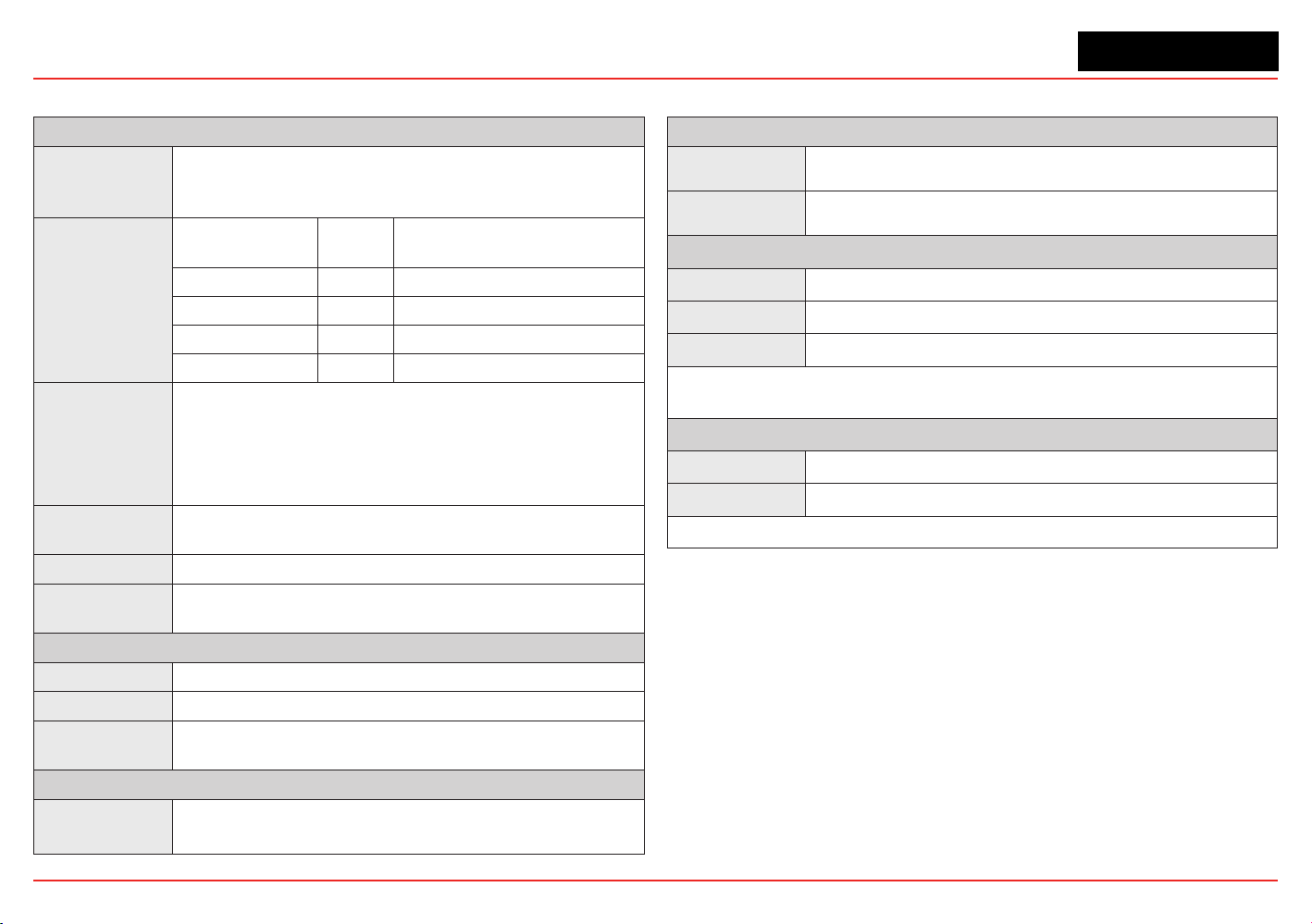
XNX Universal Transmitter
Section 6 - Specications
128
Electrical
Operating Voltage
EC/mV: 16V to 32V (24V nominal) ** Startup/Normal values **
IR: 18V to 32V (24V nominal) ** Startup/Normal values **
Power
Consumption
Conguration
Max
Power
Inrush
XNX EC 6.2 w <1A, <10ms@24VDC
XNX mV 6.5 w <750mA <2ms@24VDC
XNX IR (Optima) 9.7w <1A, <10ms@24VDC
XNX IR (Excel) 13.2w <1A, <10ms@24VDC
Termination
Crimp style pluggable with retaining screws, 12-28 AWG (2.5 to 0.5mm
2
) with
Shorting Jumpers: 14-28 AWG (2.0 to 0.5mm
2
)
NOTE:
To maintain EMC integrity, wiring must be shielded by either an integral shield
or run through conduit or pipe. Shield should provide 90% coverage
20 mA Signal
HART
®
over 3-wire 4-20mA (sink, source, or isolated) compliant with NAMUR
NE43
Cable Ports
5 – (2 right, 2 left, 1 bottom) Available in ¾” NPT, or M25
Recommended
Cable
See Section 2.2.2 Distance Considerations for Installation.
Construction
Material
LM25 Aluminum, (SS316 painted optional)
Dimensions
159 x 197 x 113.8 mm / 6.138 x 7.75 x 4.48 inches
Weight
2.27 kg (5 lb) Aluminum
5 kg (11 lb) Stainless
Mounting
XNX
®
Enclosure
Integral Mounting Lugs for Wall- or Optional Pipe-Mount, Optional Wall/Ceiling
Bracket
User Interface
Standard
Custom Backlit LCD, magnetic wand access
Optional
HART Handheld with IS Port
Environmental - Transmitter Operating
IP Rating
IP66
Temperature*
-40°C to +65°C / -40°F to +149°F
Humidity
0 to 99% RH non-condensing
*Operating temperatures will be limited by the sensors. See tables 6.2.2, 6.2.3, and 6.2.4 for more
information.
Environmental - Transmitter Storage
Temperature
-40°C to +65°C / -40°F to +149°F
Humidity
0 to 99% RH non-condensing
Unpowered battery life: (Real Time Clock) 3 years at rated storage temperature
6.1 Product Specications

XNX Universal Transmitter
129
Hazardous Area Approvals [See Section 6.2 Certifications by Part Number for other approvals (pending)]
XNX-UT**-*****
Class II, Div. 1 Groups F & G, Class II, Zone 20 & 21
FM Approvals Listed
AEx D IIB + H2 T6 -40 ºC ≤Tamb ≤65 ºC
AEx D [ia IIC} IIB + H2 T6 -40 ºC ≤Tamb ≤65 ºC (XNX UT*E-***** & XNX-UT*-*H****)
XNX-AM**-*****
UL/Demko 09 ATEX 0809943X / IEC Ex UL 09.0010X
II 2 D Ex tb IIIC T85 C Db
XNX-AM*E-***** & XNX-AM*-*H****
II 2 (1)D Ex tb [ia IIIC Da] IIIC T85 Db
XNX-BT**-*****
Class II, Div. 1 Groups F & G, Class II, Zone 20 & 21
INMETRO TUV 12.1018X
Ex d IIB + H2 T4 Gb IP 66 ≤ -40 ºC ta ≤+65 ºC
Ex d [ia IIC Ga] IIB + H2 T4 Gb IP 66 ≤-40 ºC ta ≤+65 ºC (XNX BT*E-***** & XNX-BT*-*H****)
FM Approvals Listed
AEx D IIB + H2 T6 -40 ºC ≤Tamb ≤65 ºC
AEx D [ia IIC} IIB + H2 T6 -40 º≤ Tamb ≤65 ºC (XNX BT*E-***** & XNX-BT*-*H****)
NOTES:
1. The temperature class (T6) is limited to T4 when the MPD sensor is attached locally to the transmitter.
2. XNX EC cartridges and Remote Mount Kit have been evaluated by Underwriters Laboratories (UL) to
Canadian National Standards.
3.
Peer to peer and multi-drop network (daisy chained) HART, Modbus®, and FoundationTM Fieldbus
Combustible Gas Detection and may be used only for diagnostics and data collection.
Performance Approvals
Communication Options
Relays
Type: 3 form “C” SPCO contacts for alarm and fault indication.
Rating: 250 VAC, 5A/24 VDC, 5A (2 Alarm, 1 Fault)
A remote reset is provided to silence alarms. (The Foundation Fieldbus, relay, and
Modbus options are mutually exclusive.)
Modbus
Modbus/RTU over RS-485 physical layer. Interface isolated; includes switchable
120 Ohm termination resistor.
Baud rates: 1200 to 38,400; 19,200 default.
(The Foundation Fieldbus, relay, and Modbus options are mutually exclusive.)
Foundation
Fieldbus
H1 Physical Layer.
31.25 kbit/s Manchester encoded signal.
AMIS-49200 Fieldbus MAU (media access unit).
SPC4-2 Fieldbus Controller.
Do not use Fieldbus communication in hazardous areas.
The Foundation Fieldbus, Relay, and Modbus options are mutually exclusive.
Class I, Div. 1 Groups A, B, C & D Class I, Zone 1 Group IIC
II 2 G Ex d IIC T6 (Tamb -40 °C to +65 °C) IP 66
II 2 (1)G Ex d [ia IIC Ga] IIc T6 (Tamb -40 °C to +65 °C) IP 66
Class I, Div. 1 Groups A, B, C & D Class I, Zone 1 Group IIC
Ex tb [ia IIC Da] IIIc T85 Db
Ex tb IIIC 85° Db
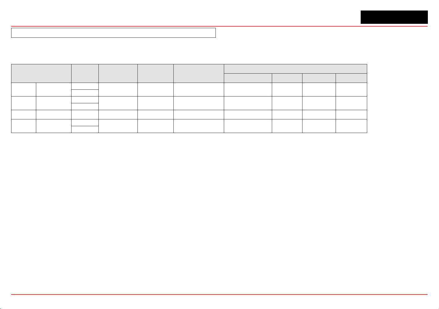
XNX Universal Transmitter
Section 6 - Specications
130
See Section 6.2 Certifications by Part Number for other approvals
6.2 Sensor Data
6.2.1 Operating and Storage Conditions for Performance Tested EC Cartridges
Gas
Cartridge
P/N
Operating Pres-
sure
Operating Air
Speed
Warm-up Time
(minimum)
Storage Conditions*
Temperature Pressure Humidity Time**
O
2
Oxygen
XNXXSO1SS
80 kPa ~ 120 kPa 0 ~ 6 m/sec 60 sec. 0 to 20°C, 32 to 68°F 80 to 120 KPa 5 to 95% RH 6 months
XNXXSO1FM
H
2
S Hydrogen Sulfide
XNXXSH1SS
80 kPa ~ 120 kPa 0 ~ 6 m/sec 60 sec. 0 to 20°C, 32 to 68°F 70 to 110 KPa 30 to 70% RH 6 months
XNXXSH1FM
H
2
S (High) Hydrogen Sulfide XNXXSH2SS 80 kPa ~ 120 kPa 0 ~ 6 m/sec 60 sec. 0 to 20°C, 32 to 68°F 70 to 110 KPa 30 to 70% RH 6 months
CO Carbon Monoxide
XNXXSC1SS
80 kPa ~ 120 kPa 0 ~ 6 m/sec 60 sec. 0 to 20°C, 32 to 68°F 70 to 110 KPa 30 to 70% RH 6 months
XNXXSC1FM
*Store in sealed packages **Check cartridge certificates

XNX Universal Transmitter
Section 6 - Specications
131
6.2.2 EC Sensor Performance Data, Factory Mutual Veried (see Section 6.3)
Gas Cartridge P/N
Selectable Full
Scale Range (Dis-
play and 4-20mA
Full Scale)
Default
Range
Range
Incre-
ments
Lower
Alarm
Limit
Lower
Detection
Limit
Lower
Explosive
Limit
(% Vol)
Zero
Deviation
Selectable
Cal Gas
Range
Default
Cal Point
Response
Time (T50)
sec
Response
Time (T90)
sec
Accuracy
Operating Temperature Operating Humidity
Min Max Min Max
O
2
Oxygen XNXXSO1FM n/a 23.0% Vol n/a 5.0%Vol 5% Vol n/a n/a
20.9 %Vol
(fixed)
20.9 %Vol T20 <10 <30 <+/-0.5 %Vol -30°C / -34°F 55°C /131°F 15% RH 90% RH
H
2
S Hydrogen Sulfide XNXXSH1FM 10.0 to 50.0 ppm 15.0 ppm 0.1 ppm 5.0 ppm 1.5 ppm n/a -2.5 ppm
30 to 70%
of the
selected full
scale range
10 ppm <20 <30
2 ppm or 10% of
reading, whichever is
greater
-40°C / -40°F 55°C / 131°F 15% RH 90% RH
CO Carbon Monoxide XNXXSC1FM
1
100 to 1000 ppm 300 ppm 100 ppm 30 ppm 15 ppm na/ -25 ppm 100 ppm <15 <30 See footnote 1 -40°C / -40°F 55°C / 131°F 15% RH 90% RH
FOOTNOTES:
1. XNXXSC1FM accuracy over temperature <±10% of reading 20°C/68°F to 55°C/131°F, <±20% of reading 20°C/68°F to -10°C/14°F, <±30% of reading -10°C/14F to -20°C/-4°F.
Recalibration is recommended if the temperature of the local environment has varied by more than -30°C.
NOTES:
• Performanceguresaremeasuredbytestunitscalibratedat50%offullscale,atambientconditionsof20°C,50%RH,withtheECweatherproofcoverattached
• IP rating of FM Cartridges is IP63.
• Barometric pressure effects on the O
2
sensor: The output from the O
2
sensor has pressure effects of <0.1% change of output per % change in pressure. When the barometric
pressure changes by ±20% the output from the O
2
sensorchanges<±0.4%Vol.However,theoxygensensorshowstransientbehaviorwhensubjectedtoarapidchangein
ambientpressureduetoeitherweatheroraltitude.Forexample,a10KPainstantaneouspositivepressurestepchangemaycauseanoverscalealarmconditionforaperiod
of about 12 seconds.
• OperatingtheXNXECsensoratextendedtemperaturerangesforaprolongedtimeperiodexceeding12hoursmycausedeteriorationinthesensorperformanceandshorten
sensorlife.ExtendedtemperaturerangeforXNXECsensorsis-40°Cot-20°C.
• Responsetimesmayincreaseatlowertemperatures.
• FM performance verification is limited to the requirements of the standards identified in Table 6.3 for each cartridge.
• ContactHoneywellAnalyticsforadditionaldataordetails.

XNX Universal Transmitter
Section 6 - Specications
132
6.2.3 EC Sensor Performance Data, DEKRA EXAM veried (see Section 6.3)
Gas Cartridge P/N
Selectable Full
Scale Range (Dis-
play and 4-20mA
Full Scale)
Default
Range
Range
Incre-
ments
Lower
Alarm
Limit
Lower
Detection
Limit
Zero
Variation
Selectable
Cal Gas
Range
Default Cal
Point
Response
Time (T50)
(sec)
T90 Response
T10 Recovery
Time (sec)
Accuracy
1
Operating Temperature Operating Humidity
Min Max Min Max
O
2
Oxygen XNXXSO1SS n/a 25.0 %Vol n/a 5.0%Vol 3.5 %Vol n/a
20.9 %Vol
(fixed)
20.9 %Vol T20 <10 <30 <+/-0.6 %Vol -30°C / -34°F 55°C /131°F 15% RH 90% RH
H
2
S
Hydrogen
Sulfide
XNXXSH1SS 10.0 to 50.0 ppm 15.0 ppm 0.1ppm 3.0 ppm 1.0 ppm 2.0 ppm
30 to 70%
of the
selected full
scale range
10 ppm <20 <30 <+/-0.3 ppm -40°C / -40°F 55°C / 131°F 15% RH 90% RH
H
2
S (High)
Hydrogen
Sulfide
XNXXSH2SS 50 to 500 ppm 100 ppm 10 ppm 5 ppm 1 ppm 2 ppm 50 ppm <20 <30 <+/-5 ppm -40°C / -40°F 55°C / 131°F 15% RH 90% RH
CO
Carbon
Monoxide
XNXXSC1SS 100 to 500 ppm 300 ppm 100 ppm 15 ppm 5 ppm 10 ppm 100 ppm <15 <30 <+/-2 ppm -40°C / -40°F 55°C / 131°F 15% RH 90% RH
FOOTNOTE:
1.AccuracyofreadingatdefaultAlarm1concentration(typically10%FSordefinedminimumalarmlevelsetting,whicheverisgreater)whenoperatedatdefaultfullscale.
NOTES:
• SensordriftbetweenLDLandnegativedriftfaultlimits(typcially>negativezerovariation)appearas0onthedisplayandoutputsofthedevice.
• Long-termdrift:XNXXSC1SS<5%/year,XNXXSO1SS<4%/year,XNXXSH1SSandXNXXSH2SS<2%/month.
• Performanceguresaremeasuredbytestunitscalibratedat50%offullscale,atambientconditionsof20°C,50%RH,withtheECweatherproofcoverattached.
• OperatingtheXNXECsensoratextendedtemperaturerangesforaprolongedtimeperiodexceeding12hoursmaycausedeteriorationinsensorperformanceandshorten
sensorlife.ExtendedtemperaturerangesforXNXECsensorcartridgesare-40°Cto-20°C.
• Barometric pressure effects on the O
2
sensor: The output from the O
2
sensor has pressure effects of <0.1% change of output per % change in pressure. When the barometric
pressure changes by ±20%, the output from the O
2
sensorchanges<±0.4%Vol.However,theoxygensensorshowstransientbehaviorwhensubjectedtoarapidchangein
ambientpressureduetoeitherweatheroraltitude.Forexample,a10KPainstantaneouspositivepressurestepchangemaycauseanoverscalealarmconditionforaperiod
of about 12 seconds.
• Responsetimesmayincreaseatlowertemperatures.
• ContactHoneywellAnalyticsforanyadditionaldataordetails.

XNX Universal Transmitter
Section 6 - Specications
133
6.2.4 Other EC Sensors
Gas Cartridge P/N
Selectable Full
Scale Range
(Display and
4-20mA Full
Scale)
Default
Range
Range
Incre-
ments
Lower
Alarm
Limit
Lower
Detection
Limit
Zero
Deviation
Selectable
Cal Gas
Range
Default
Cal Point
Response
Time (T50)
sec
Response
Time
(T90) sec
Accuracy
1
Typical
Accuracy
@ Lowest
Alarm
Level
Operating Temperature Operating Humidity
Min Max Min Max
HCl Hydrogen Chloride XNXXSR1SS 10.0 to 20.0 ppm 10.0 ppm 1.0 ppm 5.0 ppm 0.6 ppm -1.0 ppm
30 to 70%
of the
selected full
scale range
5.0 ppm
<45
2, 3
<150
2, 3
<+/-1.0 ppm or
20%
of applied gas
2, 3
<+/-1.0 @
3 ppm
-20°C/-4°F 40°C/104°F 15% RH 90% RH
H
2
S (Low) Hydrogen Sulfide XNXXSH3SS n/a 15.0 ppm n/a 3.0 ppm 1.0 ppm -2.5 ppm 10 ppm <20 <40 <+/-0.3 ppm
<+/-0.3 @
3 ppm
-40°C / -40°F 55°C / 131°F 15% RH 90% RH
SO
2
Sulfur Dioxide XNXXSS1SS 5.0 to 20.0 ppm 15.0 ppm 5.0 ppm 2.0 ppm 0.6 ppm -1.0 ppm 5.0 ppm <15 <30 <+/-0.3 ppm
<+/-0.3 @
2 ppm
-40°C / -40°F 55°C / 131°F 15% RH 90% RH
SO
2
(High) Sulfur Dioxide XNXXSS2SS 20.0 to 50.0 ppm 50.0 ppm 10.0 ppm 5.0 ppm 1.5 ppm -2.5 ppm 25 ppm <15 <30 <+/-0.6 ppm
<+/-0.6 @
5 ppm
-40°C / -40°F 55°C / 131°F 15% RH 90% RH
NH
3
Ammonia XNXXSA1SS 50 to 200 ppm 200 ppm 50 ppm 20 ppm 6 ppm -10 ppm 100 ppm <60 <180 <+/-4 ppm
<+/-4 @
20 ppm
-20°C / -4°F 40°C / 104°F 15% RH 90% RH
NH
3
(High) Ammonia XNXXSA2SS 200 to 1000 ppm 1,000 ppm 50 ppm 100 ppm 30 ppm -50 ppm 300 ppm <60 <180 <+/-20 ppm
<+/-20 @
100 ppm
-20°C / -4°F 40°C / 104°F 15% RH 90% RH
Cl
2
Chlorine XNXXSL2SS n/a 5.00 ppm n/a 0.50 ppm 0.15 ppm -0.25 ppm 2.0 ppm <20 <60 <+/-0.2 ppm
<+/-0.20 @
0.50 ppm
-10°C / 14°F 55°C / 131°F 15% RH 90% RH
Cl
2
(High) Chlorine XNXXSL1SS 5.0 to 20.0 ppm 5.0 ppm 5.0 ppm 1.0 ppm 0.6 ppm -1.0 ppm 2.0 ppm <20 <30 <+/-0.2 ppm
<+/-0.2 @
1 ppm
-10°C / 14°F 55°C / 131°F 15% RH 90% RH
ClO
2
Chlorine Dioxide XNXXSX1SS n/a 1.00 ppm n/a 0.10 ppm 0.03 ppm -0.05 ppm 0.5 ppm <30 <120 <+/-30%
<+/-0.03 @
0.1 ppm
-20°C / -4°F 55°C / 131°F 15% RH 90% RH
NO
Nitrogen
Monoxide
XNXXSM1SS n/a 100 ppm n/a 10 ppm 3 ppm -5 ppm 50 ppm <15 <30 <+/-2 ppm
<+/-2.0 @
10 ppm
-20°C / -4°F 55°C / 131°F 15% RH 90% RH
NO
2
Nitrogen Dioxide XNXXSN1SS 5.0 to 50.0 ppm 10.0 ppm 5.0 ppm 5.0 ppm 1.5 ppm -2.5 ppm 5 ppm <15 <30 <+/-0.2 ppm
<+/-0.2 @
5 ppm
-20°C / -4°F 55°C / 131°F 15% RH 90% RH
H
2
Hydrogen XNXXSG1SS n/a 1,000 ppm n/a 100 ppm 30 ppm -50 ppm 500 ppm <60 <90
2
<+/-8 ppm
<+/-8 @
100 ppm
-20°C / -4°F 55°C / 131°F 15% RH 90% RH
H
2
(High) Hydrogen XNXXSG2SS n/a
10,000
ppm
n/a 1000 ppm 300 ppm -500 ppm 5000 ppm <15 <30 <+/-150 ppm
<+/-150 @
1000 ppm
-20°C / -4°F 55°C / 131°F 15% RH 90% RH
HF Hydrogen Fluoride XNXXSF1SS n/a 12.0 ppm n/a 1.5 ppm 0.4 ppm -0.6 ppm 5.0 ppm 120 <240 <+/-0.5 ppm
<+/-0.5 @
1.5 ppm
-20°C / -4°F 55°C / 131°F 20% RH 75% RH
PH
3
Phosphine XNXXSP1SS n/a 1.20 ppm n/a 0.15 ppm 0.04 ppm -0.06 ppm 0.5ppm <15 <30 <+/- 0.02 ppm
<+/-0.02 @
0.15 ppm
-20°C / -4°F 40°C / 104°F 10% RH 90% RH
see footnotes and notes on following page

XNX Universal Transmitter
Section 6 - Specications
134
FOOTNOTES (SEE TABLE ON PREVIOUS PAGE):
1.AccuracyofreadingatdefaultAlarm1concentration(typically10%FSordefinedminimumalarmlevelsetting,whichevergreater)whenoperatedatdefaultfullscale.
2.Systemconditioningmayberequiredtoachievestatedresults.ContactHoneywellAnalyticsfordetails.
3.Measuredusingcalibrationflowhousingatcalibrationflowrate(300-375ml/min)withdrygas.
NOTES (SEE TABLE ON PREVIOUS PAGE):
• Datatakenatambientconditionsof20°C,50%RH.
• Datarepresentstypicalvaluesoffreshlycalibratedsensorswithoutoptionalaccessoriesattached.
• Performanceguresaremeasuredbytestunitscalibratedat50%offullscale.
• Standard temperaturerangeforXNXECSensorsis-20°Cto+55°C;ATEX,IECEx.
• ExtendedtemperaturerangesfortheXNXECSensorsare-40°Cto-20°C
• Accuracybetweenthetemperaturesof-40°Cand-20°Cis±30%attheappliedgasconcentration.
• OperatingtheXNXECSensorsatextendedtemperaturerangesforaprolongedtimeperiodexceeding12hoursmaycausedeteriorationinsensorperformanceandshorter
sensor life.
• Barometric pressure effects on the O
2
sensor: The output from the O
2
sensor has pressure effects of <0.1% change of output per % change in pressure. When the barometric
pressure changes by ±20% the output from the O
2
sensorchanges<±0.4%Vol.However,theoxygensensorshowstransientbehaviorwhensubjectedtoarapidchangein
ambientpressureduetoeitherweatheroraltitude.Forexample,a10KPainstantaneouspositivepressurestepchangemaycauseanoverscalealarmconditionforaperiod
of about 12 seconds.
• Recalibration is recommended if the temperature of local environment has varied by more than ±15°C from the temperature of calibration.
• Responsetimesmayincreaseatlowertemperatures.
• ContactHoneywellAnalyticsforanyadditionaldataordetails.
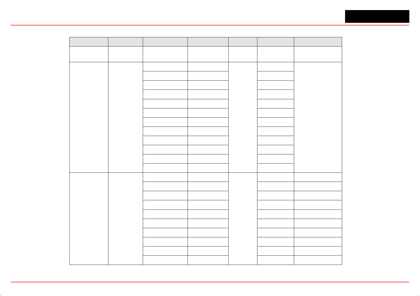
XNX Universal Transmitter
Section 6 - Specications
135
6.2.5 XNX EC Sensor Cross-sensitivity
Gas type Part Number Gas Type Applied Concentration Unit Reading Unit
O
2
XNXXS01SS
XNXXSO1FM
Carbon Dioxide 5 %vol 0.1
%vol (change O
2
reading) per %vol CO
2
HCl XNXXSR1SS
Carbon monoxide 2000
ppm
0
ppm HCl
Hydrogen 20000 0
Chlorine 5 5.6
Nitrogen dioxide 5 0.9
Propan-2-ol 500 0
Methanol 500 0
Hydrogen fluoride 5 6.7
Hydrogen suflfide 25 -3.6
Sulphur dioxide 50 22.4
Arsine 1 0
Phosphine 1 -0.14
Diborane 1 -1.3
H
2
S
(Low Range)
XNXXSH3SS
Ammonia 50
ppm
0 ppm H
2
S
Carbon Monoxide 100 <2 ppm H
2
S
Carbon Dioxide 5000 0 ppm H
2
S
Chlorine 0.5 0 ppm H
2
S
Ethylene 100 0 ppm H
2
S
Hydrogen 100 0 ppm H
2
S
Hydrogen Sulfide 10 10 ppm H
2
S
Nitrogen Monoxide 25 0 ppm H
2
S
Nitrogen Dioxide 3 0 ppm H
2
S
Sulfur Dioxide 2 0 ppm H
2
S
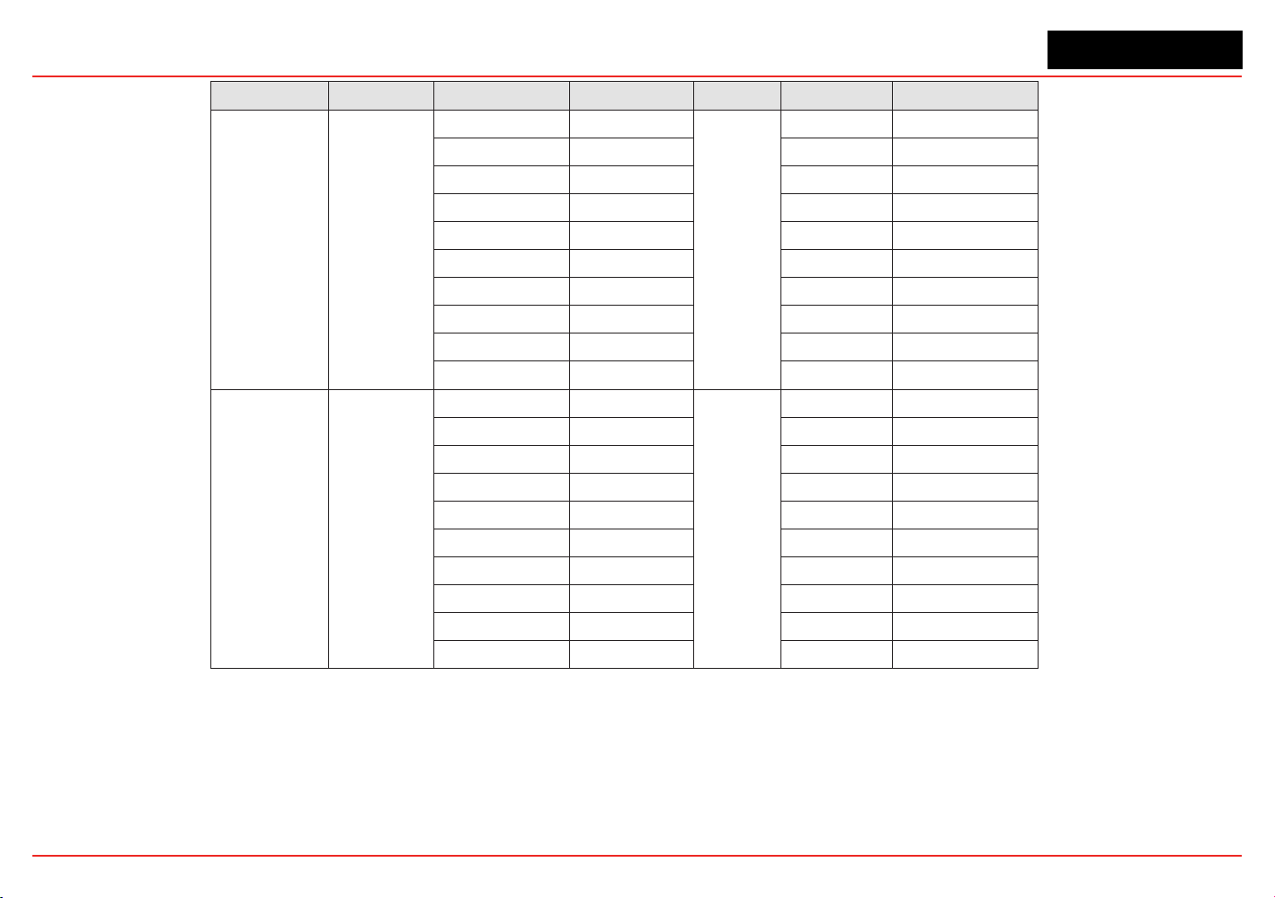
XNX Universal Transmitter
Section 6 - Specications
136
Gas type Part Number Gas Type Applied Concentration Unit Reading Unit
H
2
S
XNXXSH1SS
XNXXSH1FM
Ammonia 50
ppm
0 ppm H
2
S
Carbon Monoxide 100 <2 ppm H
2
S
Carbon Dioxide 5000 0 ppm H
2
S
Chlorine 0.5 0 ppm H
2
S
Ethylene 100 0 ppm H
2
S
Hydrogen 100 0 ppm H
2
S
Hydrogen Sulfide 10 10 ppm H
2
S
Nitrogen Monoxide 25 0 ppm H
2
S
Nitrogen Dioxide 3 0 ppm H
2
S
Sulfur Dioxide 2 0 ppm H
2
S
H
2
S
(High Range)
XNXXSH2SS
Ammonia 50
ppm
0 ppm H
2
S
Carbon Monoxide 100 <2 ppm H
2
S
Carbon Dioxide 5000 0 ppm H
2
S
Chlorine 0.5 0 ppm H
2
S
Ethylene 100 0 ppm H
2
S
Hydrogen 100 0 ppm H
2
S
Hydrogen Sulfide 10 10 ppm H
2
S
Nitrogen Monoxide 25 0 ppm H
2
S
Nitrogen Dioxide 3 0 ppm H
2
S
Sulfur Dioxide
2 0 ppm H
2
S

XNX Universal Transmitter
Section 6 - Specications
137
Gas type Part Number Gas Type Applied Concentration Unit Reading Unit
CO
XNXXSC1SS
XNXXSC1FM
Acetone 1000
ppm
0 ppm CO
Acetylene 40 80 ppm CO
Ammonia 100 0 ppm CO
Carbon Monoxide 100 100 ppm CO
Chlorine 2 0 ppm CO
Ethanol 2000 3 ppm CO
Ethylene 100 85 ppm CO
Hydrogen 100 20 ppm CO
Hydrogen Sulfide 25 0 ppm CO
Iso-Propanol 200 0 ppm CO
Nitrogen Monoxide 50 8 ppm CO
Nitrogen Dioxide 800 20 ppm CO
Sulfur Dioxide 50 0.5 ppm CO
SO
2
XNXXSS1SS
Carbon Monoxide 300
ppm
<3 ppm SO
2
Hydrogen Sulfide 15 0 ppm SO
2
Nitrogen Monoxide 35 0 ppm SO
2
Nitrogen Dioxide 5 ~-5 ppm SO
2
SO
2
XNXXSS2SS
Carbon Monoxide 300
ppm
<3 ppm SO
2
Hydrogen Sulfide 15 0 ppm SO
2
Nitrogen Monoxide 35 0 ppm SO
2
Nitrogen Dioxide 5 ~-5 ppm SO
2

XNX Universal Transmitter
Section 6 - Specications
138
Gas type Part Number Gas Type Applied Concentration Unit Reading Unit
NH
3
XNXXSA1SS
Alcohols 1000
ppm
0 ppm NH
3
Carbon Dioxide 5000 0 ppm NH
3
Carbon Monoxide 100 0 ppm NH
3
Hydrocarbons % range 0 ppm NH
3
Hydrogen 10000
ppm
0 ppm NH
3
Hydrogen Sulfide 20 2 ppm NH
3
NH
3
(High Range)
XNXXSA2SS
Alcohols 1000
ppm
0 ppm NH
3
Carbon Monoxide 100 0 ppm NH
3
Chlorine 5 0 ppm NH
3
Nitrogen Dioxide 10 0 ppm NH
3
Sulfur Dioxide 20 -40 ppm NH
3
Hydrogen 3000 0 ppm NH
3
Hydrogen Sulfide 20 20 ppm NH
3
Cl
2
XNXXSL2SS
Carbon Dioxide 20000
ppm
0 ppm Cl
2
Hydrogen Chloride 9 1.25 ppm Cl
2
Hydrogen Sulfide 25 -16.3 ppm Cl
2
Nitrogen Dioxide 50 1.25 (transient) ppm Cl
2
Sulfur Dioxide 50 9.1 ppm Cl
2
Cl
2
(High Range)
XNXXSL1SS
Carbon Dioxide 20000
ppm
0 ppm Cl
2
Hydrogen Chloride 9 1.25 ppm Cl
2
Hydrogen Sulfide 25 -16.3 ppm Cl
2
Nitrogen Dioxide 50 1.25 (transient) ppm Cl
2
Sulfur Dioxide 50 9.1 ppm Cl
2
ClO
2
XNXXSX1SS Refer To Cl2 Refer to Cl
2
Refer to Cl
2
Refer to Cl
2
Refer to Cl
2
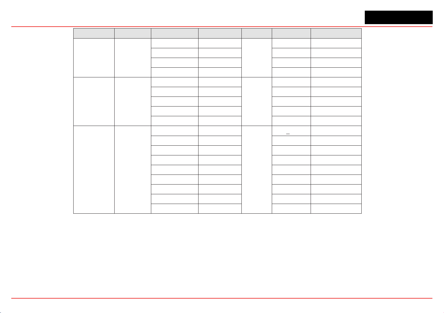
XNX Universal Transmitter
Section 6 - Specications
139
Gas type Part Number Gas Type Applied Concentration Unit Reading Unit
NO XNXXSM1SS
Carbon Monoxide 300
ppm
0 ppm NO
Sulfur Dioxide 5 0 ppm NO
Nitrogen Dioxide 5 <1.5 ppm NO
Hydrogen Sulfide 15 ~1.5 ppm NO
NO
2
XNXXSN1SS
Carbon Monoxide 300
ppm
0 ppm NO
2
Hydrogen Sulfide 15 ~ -1.2 ppm NO
2
Sulfur Dioxide 5 0 ppm NO
2
Nitrogen Monoxide 35 0 ppm NO
2
Chlorine 1 ~1 ppm NO
2
H
2
XNXXSG1SS
Carbon Monoxide 300
ppm
< 60 ppm H
2
Hydrogen Sulfide 15 <3 ppm H
2
Sulfur Dioxide 5 0 ppm H
2
Nitrogen Monoxide 35 »10 ppm H
2
Nitrogen Dioxide 5 0 ppm H
2
Chlorine 1 0 ppm H
2
Hydrogen Cyanide 10 »3 ppm H
2
Hydrogen Chloride 5 0 ppm H
2
Ethylene 100 »80 ppm H
2

XNX Universal Transmitter
Section 6 - Specications
140
Gas type Part Number Gas Type Applied Concentration Unit Reading Unit
H
2
(High Range) XNXXSG2SS
Ammonia 100 ppm 0 ppm H
2
Arsine 0.2 ppm 0 ppm H
2
Carbon Dioxide 1000 ppm 0 ppm H
2
Carbon Monoxide 100 ppm 150 ppm H
2
Chlorine 1 ppm 0 ppm H
2
Ethylene 500 ppm yes; n/d ppm H
2
Hydrogen Cyanide 20 ppm 0 ppm H
2
Hydrogen Sulfide 20 ppm 4 ppm H
2
Iso-Propanol 1100 ppm yes; n/d ppm H
2
Methane 1 % 0 ppm H
2
Nitrogen Dioxide 10 ppm -40 ppm H
2
Ozone 0.25 ppm 0 ppm H
2
Sulfur Dioxide 5 ppm 0 ppm H
2
HF XNXXSF1SS
Carbon Monoxide 2000 ppm 0 ppm HF
Hydrogen 20000 ppm 0 ppm HF
Chlorine 5 ppm 5.8 ppm HF
Nitrogen Dioxide 5 ppm 0.65 ppm HF
Iso-Propanol 500 ppm 0 ppm HF
Methanol 500 ppm 0 ppm HF
Hydrogen Fluoride 5 ppm 7 ppm HF
Hydrogen Sulfide 25 ppm -3.6 ppm HF
Sulfur Dioxide 50 ppm
28.3 ppm HF
Arsine 1 ppm 0 ppm HF
Phosphine 1 ppm -0.14 ppm HF
Diborane 1 ppm -1.3 ppm HF
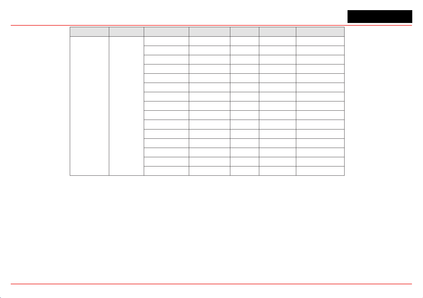
XNX Universal Transmitter
Section 6 - Specications
141
Gas type Part Number Gas Type Applied Concentration Unit Reading Unit
PH
3
XNXXSP1SS
Carbon Monoxide 2000 ppm <10 ppm PH
3
Hydrogen 5000 ppm <10 ppm PH
3
Chlorine 1 ppm -70 ppm PH
3
Nitrogen Dioxide 8 ppm -860 ppm PH
3
Ethanol 2000 ppm <10 ppm PH
3
Iso-Propanol 1000 ppm <10 ppm PH
3
Hydrogen Chloride 10 ppm <10 ppm PH
3
Hydrogen Fluoride 10 ppm <10 ppm PH
3
Hydrogen Sulfide 0.5 ppm 70 ppm PH
3
Ammonia 100 ppm 1050 (transient) ppm PH
3
Sulfur Dioxide 50 ppm 550 (transient) ppm PH
3
Silane 1 ppm 364 ppm PH
3
Arsine 1 ppm 680 ppm PH
3
Diborane 1 ppm 454 ppm PH
3
Germane 1 ppm 454 ppm PH
3
NOTES:
• Theguresofcross-sensitivityaretypicalvaluesandshouldnotbeusedasabasisforcrosscalibration.
• Cross-sensitivities may not be linear and should not be scaled.
• For some cross-interferentsbreakthroughmayoccurifgasisappliedalongertimeperiod.
• Therearemanygasesandvaporsthatcanpoisonelectochemicalcells.Itisdifculttogiveacompleteandexclusivelistofallspecies
whichwillhaveaneffectonthesensors.However,thesearesomecommonsubstanceswhichshouldbeavoided:
• Airbornegreases-Thesemayblockgasaccessintothesensorsandthereforereducesensitivity.
• Siliconecompounds-Theseareoftenfoundinsprays,aerosols,lubricants,polishes,adhesives,sealants,zebrastrip,cleaningagents,
andoorwaxes.Thesecompoundstendtoreducethesensitivityofthesensorsandgenerallywillhaveapermanenteffect.
• Solvents and organicvapors-Manyorganicvaporswilldamagethesensors.SomecommononesareIPA,toluene,xylene,other
benzinederivatives,petrol,anddiesel.Itisdifculttogiveafulllistoforganicvapors,astherearesomanyofthem.Generally,any
organic vapor should be avoided.
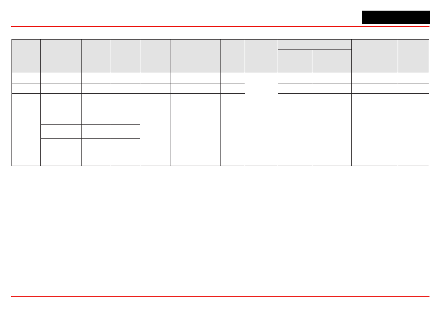
XNX Universal Transmitter
Section 6 - Specications
142
6.2.6 XNX MPD Sensor Performance Data
Sensor
Type
Gas
Typical
Response
Time
(T50) sec
Typical
Response
Time
(T90) sec
Maximum
Range
Accuracy
(% of full scale or
% of applied gas)
Drift
Over
Time
Operating
Humidity
Operating Temperature
Operating
Pressure
Operating
Air Speed
Min Max
MPD-IC1 Carbon Dioxide <30 <70
5.00 %Vol
±5%FS or ±15% < 3%/yr
0-95%
RH non-
condensing
-20°C / -4°F +50°C / 122°F 80kPa ~ 110kPa 0 ~ 6m/sec
MPD-IV1 Methane <15 <30
5.00 %Vol
±5%FS or ±15% < 3%/yr -20°C / -4°F +50°C / 122°F 80kPa ~ 110kPa 0 ~ 6m/sec
MPD-IF1 Propane <15 <30
100 %LEL
±5%FS or ±15% < 3%/yr -20°C / -4°F +50°C / 122°F 80kPa ~ 110kPa 0 ~ 6m/sec
MPD-CB1
Propane <15 <30
100 %LEL
±5%FS or ±15% < 3%/yr
-40°C /
-40°F
+65°C / 149°F 80kPa ~ 120kPa 0 ~ 6m/sec
Methane <10 <30
Hydrogen <10 <30
Butane-2 <15 <40
Nonane <20 <50
NOTES:
• Responsetimesmayvarydependinguponmolecularweight,size,andstructure.
• CSAapprovedhydrogensensorsareMPDUT-CB1and705STD.
• DEKRAEXAMapprovedsensorsareMPDAMCB1andSPHT
• Datatakenat20-25°C.ContactHoneywellAnalyticsforadditionaldataordetails.
• Responsetimesmayincreaseatlowertemperatures.
• Datarepresentstypicalvalueswithoutoptionalaccessoriesattached.
• Systemconditioningmayberequiredtoachievestatedresults.ContactHoneywellAnalyticsfordetails.
• Performanceguresaremeasuredusingasamplehumidityof50%RH.
• Performanceguresaremeasuredbetween40and60%offullscale.
• Performanceguresaremeasuredbytestunitscalibratedat50%offullscale.
• Useoftheweatherproofcapwillincreaseresponsetimes.
• FM6340performanceapprovalbasedonMPD-IC1withSPXCDWPT50<60T90<150.
• Useoftheweatherproofcapwillincreaseresponsetimes.
• FM6340performanceapprovalbasedonMPD-IC1withSPXCDWPT50<60T90<150.
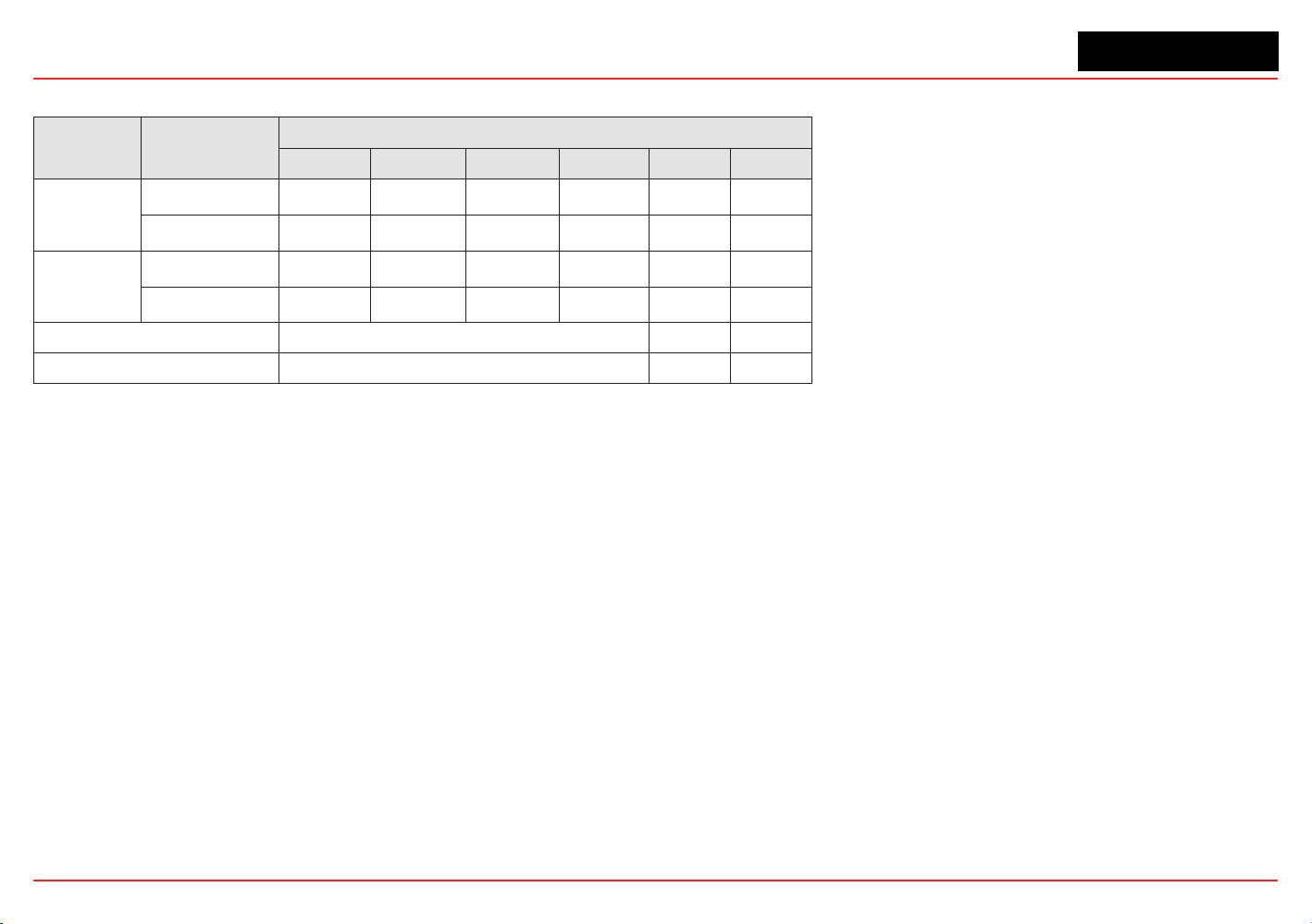
XNX Universal Transmitter
Section 6 - Specications
143
6.2.7 EN60079-29-1 Performance Approved Gases for mV Sensor Types
Sensor Type
EN60079-29-1
Reference
Veried Gas Selections
Hydrogen Methane-2 Propane-2 Butane-2 Star 2 Star 4
MPD AMCB1
Standard Test Gas
l l
Other Gases
l l
n-nonane
SP-HT
Standard Test Gas
l l
Other Gases
l l
n-nonane
Max Zero Deviation (see note 1) -7% LEL -9% LEL -7% LEL
LDL (see note 2) 3% LEL 5% LEL 3% LEL
NOTES:
1. Readings<0%LELarenotdisplayedorindicatedonthe20mAoutput.ValuesexceedingthezerodeviationlimitwillresultinF111faults.
2. Readings<LDLareshownas0%onthedisplayand20mAoutput.
6.2.8 Other Sensor Performance Data
Performance data for other supported sensors is available in their respective technical manuals.
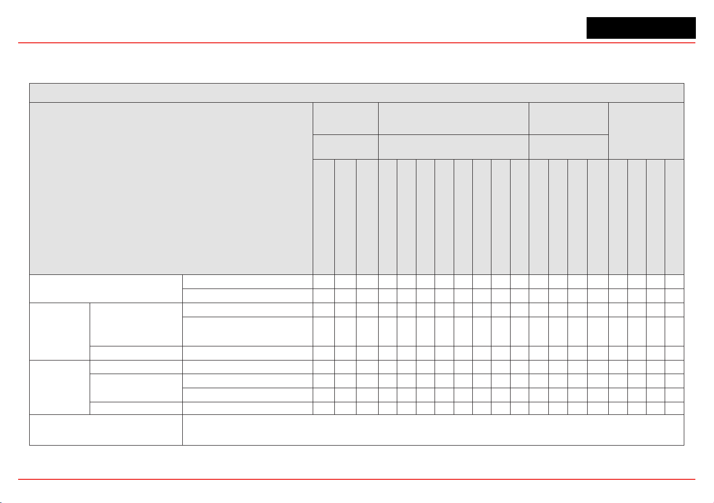
XNX Universal Transmitter
Section 6 - Specications
144
6.3 XNX Certications by Part Number Series
ContactHoneywellAnalyticsforinformationaboutapprovalsnotshowninthissection.
XNX Certications XNX-UT Series
XNX Part Number Series
XNX
Transmitter IR
Personality
XNX Transmitter mV Personality
XNX Transmitter
EC Personality
Options
XNX-UTSI-*****
XNX-UTAI-*****
XNX-UTSV-***** / XNX-UTAV-*****
XNX-UTSE-***** /
XNX-UTAE-*****
With Generic 20 mA Input
With Optima Plus
With Searchline Excel
MPD-UTCB1 (Cat Bead)
MPD-UTIV1 (IR Methane)
MPD-UTIF1 (IR Flam)
MPD-UTIC1 (IR CO
2
)
with 705
with Sensepoint
with Sensepoint PPM
with Sensepoint HT
With XNXXSO1FM O
2
Cartrdige
With XNXXSH1FM H
2
S Cartridge
With XNXXSC1FM CO Cartridge
SO
2
, NH
3
, Cl
2
, ClO
2
, NO, NO
2
, H
2
PPM HCL, HCN, HF, O
3
, PH
3
Modbus
Relays
Local HART
Foundation Fieldbus
C-UL Classied
For Hazardous Locations
UL 1203 T T T T T T T T N/A N/A N/A T T T T T T T T
UL 913-7th Edition N/A N/A N/A N/A N/A N/A N/A N/A N/A N/A N/A T T T T N/A N/A T N/A
CSA
Hazardous Location
CAN/CSA C22.2 No. 30 M-1986 T T T T N/A N/A T T N/A N/A N/A T T T T T T T N/A
CAN/CSA C22.2 No. 157-92
(Applies to Local HART Option and/or
EC Adaptors)
N/A N/A N/A N/A N/A N/A N/A N/A N/A N/A N/A T
T T T N/A N/A T N/A
Performance CSA C22.2 No. 152 N/A T N/A T N/A N/A N/A T N/A N/A N/A N/A N/A N/A N/A T T T T
FM Listed
US Toxic Performance Standard referenced in notes 1, 2, 3 N/A N/A N/A N/A N/A N/A 3 N/A N/A N/A N/A 1 2 3 N/A T T T T
Flammable Performance
FM 6310 / 6320 N/A T N/A T N/A N/A N/A T N/A N/A N/A N/A N/A N/A N/A T T T T
FM 6325 N/A N/A T N/A N/A N/A N/A N/A N/A N/A N/A N/A N/A N/A N/A T T T T
Toxic Gas Detector FM 6340 N/A N/A N/A N/A N/A N/A T N/A N/A N/A N/A N/A N/A N/A N/A T T T T
T = 3/4 NPT threaded Transmitters & Adapters
N/A = Not Applicable
1. ANSI/ISA 92.04.01, Part 1 2007
2. ISA 92.0.01, Part 3 1998
3. FM 6340
XNX Universal Transmitter
Section 6 - Specications
145
XNX Certications by XNX-AM Series
XNX Part Number Series
XNX Transmitter
IR Personality
XNX Transmitter mV Personality XNX Transmitter EC Personality
Options
XNX-AMSI-*****
XNX-AMAI-*****
XNX-AMSV-***** / XNX-AMAV-***** XNX-AMSE-***** / XNX-AMAE-*****
With Generic 20 mA Input
With Optima Plus
With Searchline Excel
MPD-AMCB1 (Cat Bead)
MPD-AMIV1 (IR Methane)
MPD-AMIF1 (IR Flam)
MPD-AMIC1 (IR CO
2
)
With 705 HT
With Sensepoint
With Sensepoint PPM
With Sensepoint HT
With Oxygen Cartrdige
With H
2
S Low Cartridge
With H
2
S Med Cartridge
With H
2
S High Cartridge
With CO Cartridge
SO
2
, NH
3
, Cl
2
, ClO
2
, NO, NO
2
,
H
2
PPM HCL, HCN, HF, O
3
, PH
3
Modbus
Relays
Local HART
Foundation Fieldbus
Electromagnetic &
Safety;
CE Mark
EMC Compliance
EU directive 2004/108/EC
M M M M M M M M M M M M M M M M M M M M M
EN 50270:2006
B B B B B B B B B B B B B B B B B B B B B
EU directive 94/9/EC
M M M M M M M M M M M M M M M M M M M M M
Hazardous Location
---
ATEX/DEMKO
IECEx
EN 60079-29-0: 2009
M M M M M M M N/A M M M M M M M M M M M M M
EN 60079-29-1: 2007
M M M M M M M N/A M M M M M M M M M M M M M
EN 60079-11: 2012
N/A N/A N/A N/A N/A N/A N/A N/A N/A N/A N/A M M M M M M N/A N/A M N/A
EN 60079-26: 2007
N/A N/A N/A N/A N/A N/A N/A N/A N/A N/A N/A M M M M M M N/A N/A N/A N/A
IEC 60079-31 1st Ed
M M M M M M M N/A N/A N/A M M M M M M M M M M M
IEC 60079-0 6th Ed
M M M M M M M N/A M M M M M M M M M M M M M
IEC 60079-1 6th Ed
M M M M M M M N/A M M M M M M M M M M M M M
IEC 60079-11 6th Ed
N/A N/A N/A N/A N/A N/A N/A N/A N/A N/A N/A M M M M M M N/A N/A M M
IEC 60079-26 2nd Ed
N/A N/A N/A N/A N/A N/A N/A N/A N/A N/A N/A M
1
M
1
M
1
M
1
M
1
M
1
N/A N/A N/A N/A
EN 60079-31: 2009
M M M M M M M N/A N/A N/A M M M M M M M M M M M
B = Both 3/4 NPT and M25
M=M25threadedTransmitters&Adapters
M
1
=WhenusedwithS3KRMKinaZone0location
N/A=NotApplicable
XNX Universal Transmitter
Section 6 - Specications
146
XNX Certications XNX-AM Series
XNX Part Number Series
XNX Transmitter
IR Personality
XNX Transmitter mV Personality
XNX Transmitter EC
Personality
Options
XNX-AMSI-*****
XNX-AMAI-*****
XNX-AMSV-***** / XNX-AMAV-*****
XNX-AMSE-***** / XNX-
AMAE-*****
With Generic 20 mA Input
With Optima Plus
With Searchline Excel
MPD-AMCB1 (Cat Bead)*
MPD-AMIV1 (IR Methane)
MPD-AMIF1 (IR Flam)
MPD-AMIC1 (IR CO
2
)
With 705 HT
With Sensepoint
With Sensepoint PPM
With Sensepoint HT*
With XNXXSO1SS O
2
Cartrdige
With XNXXSH1SS H
2
S
Cartridge
With XNXXSH2SS H
2
S
Cartridge
With XNXXSC1SS CO
Cartridge
SO
2
, NH
3
, Cl
2
, ClO
2
, NO, NO
2
,
H
2
PPM HCL, HCN, HF, O
3
, PH
3
Modbus
Relays
Local HART
Foundation Fieldbus
Performance*
EXAM
DEKRA GmbH
IEC 60079-29-1:2007***
EN 60079-29-1:2007***
N/A M N/A M N/A N/A N/A N/A N/A N/A M N/A N/A N/A N/A N/A N/A M M N/A
EN 45544:1999 N/A N/A N/A N/A N/A N/A N/A N/A N/A N/A N/A N/A M M M N/A N/A M M N/A
EN 50104:2010** N/A N/A N/A N/A N/A N/A N/A N/A N/A N/A N/A M N/A N/A N/A N/A N/A M M N/A
EN 50271:2010 N/A M N/A M N/A
N/A N/A N/A N/A N/A M M M M M N/A N/A M M N/A
TÜV Rhineland
IEC61508 B B B N/A N/A N/A N/A B B B B B B B B B N/A N/A N/A N/A
EN 50402 B B B N/A N/A N/A N/A B B B B B B B B B N/A N/A N/A N/A
DelaysresultingfromtransmissionerrorsbetweensensorandtransmitterextendresponsetimesT90bymorethanone-third.Theperioduntilfaultindicationis10seconds.
M=M25threadedTransmitters&Adapters
B=BothXNX-UT**-*****3/4”NPTandXNX-AM**-*****transmitters
N/A=NotApplicable
*Testedcomponents:handheldinpoint-to-pointmode,weatherproofcap(notusedforcalibration),calibrationmask.
**Testedapplications:oxygendeciencyandoxygenenrichment
***Testedgases:methane-2,butane-2,propane-2,hydrogen,n-nonane
XNX Universal Transmitter
Specications
151
XNX Certications - MPD-BT**.***** Part Number Series
XNX Part Number Series
XNX Transmitter
IR Personality
XNX Transmitter mV Personality
XNX Transmitter EC
Personality
Options
XNX-BTSI-*****
XNX-BTAI-*****
XNX-BTSV-*****
XNX-BTAV-*****
XNX-BTSE-*****
XNX-BTAE-*****
With Generic 20 mA Input
With Optima Plus
With Searchline Excel
MPD-BTCB1 (Cat Bead)
MPD-BTIV1 (IR Methane)
MPD-BTIF1 (IR Flam)
MPD-BTIC1 (IR CO2 )
with 705 HT
With XNXXSO1FM O
2
Cartrdige
With XNXXSH1FM H
2
S Cartridge
With XNXXSC1FM CO Cartridge
SO
2
, NH
3
, CL
2
, ClO
2
, NO, NO
2
, H
2
PPM HCL, HCN, HF, O
3
, PH
3
Modbus
Relays
Local HART
FOUNDATION Field Bus
UL Classied
UL 1203 T T T T T T T T T T T T T T T T
UL 913-7th Edition Applies to Local HART Option) N/A N/A N/A N/A N/A N/A N/A N/A T T T T N/A N/A T N/A
INMETRO
TÜV Rheinland
ABNT NBR IEC 60079-0:2008 B B B B B B B B B B B B B B B B
ABNT NBR IEC 60079-1:2009 B B B B B B B B B B B B B B B B
ABNT NBR IEC 60079-11:2013 N/A N/A N/A N/A N/A N/A N/A N/A B B B B N/A N/A T N/A
ABNT NBR IEC 60079-26:2008 B B B B B B B B B B B B B B B B
ABNT NBR IEC 60079-31:2014 B B B B B B B B B B B B B B B B
Portar:a INMETRO n°179 de 18/05/2010 B B B B B B B B B B B B B B B B
ABNT NBR IEC 60529-:2009 T T T T T T T T T T T T T T T T
FM Listed
Standard referenced in notes 1, 2, 3
N/A N/A N/A N/A N/A N/A 3 N/A 1 2 3 N/A
T T T T
FM 6310 / 6320
N/A T N/A T N/A N/A N/A T N/A N/A N/A N/A
T T T T
FM 6325
N/A N/A T N/A N/A N/A N/A N/A N/A N/A N/A N/A
T T T T
FM 6340
N/A N/A N/A N/A N/A N/A T N/A N/A N/A N/A N/A
T T T T
T = 3/4 NPT threaded Transmitters & Adapters
N/A = Not Applicable
1. ANSI/ISA 92.04.01, Part 1 2007
2. ISA 92.0.01, Part 3 1998
3. FM 6340
147
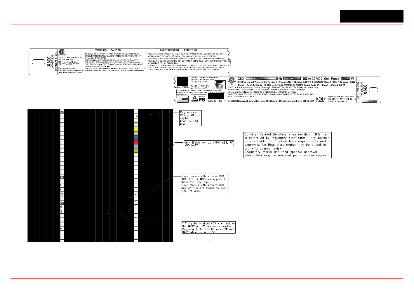
XNX Universal Transmitter
Specications
152
6..3.1 Certification Labels
Figure229.XNX-UT**-*****conguration
148
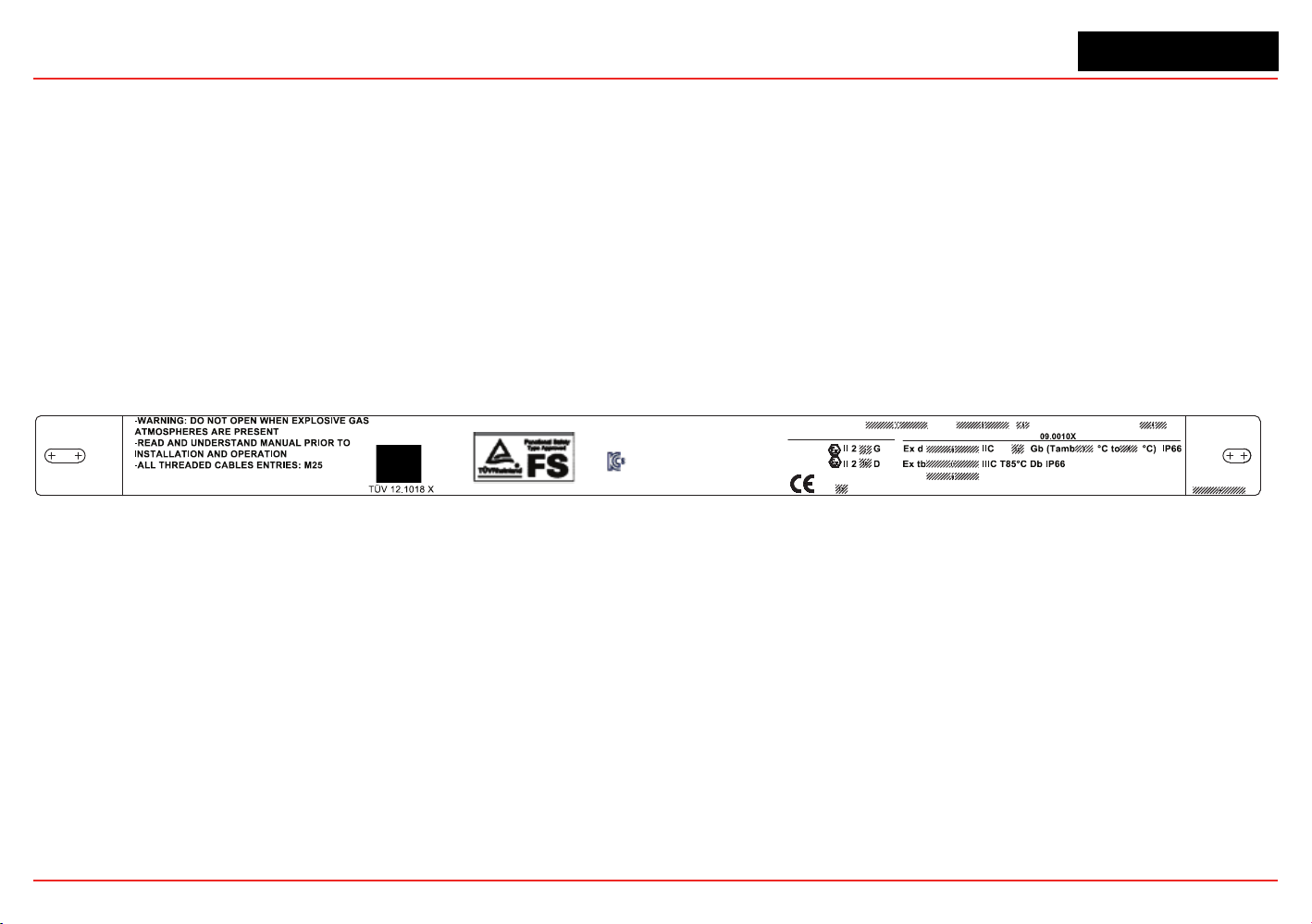
XNX Universal Transmitter
Specications
149
Certification Labels
XNX
UNIVERSAL
TRANSMITTER
XNX
UNIVERSAL
TRANSMITTER
Honeywell Analytics, Inc; 405 Barclay Blvd, Lincolnshire, IL 60069 USA
XNX- SN: to 32 VDC Max. Pmax = W
MADE IN USA
ATENÇÃO-NÃO ABRA ONDE UMA ATMOSFERA
EXPLOSIVA POSSA ESTAR PRESENTE
11-KB4BO-0120X
1180
0539
0539
XNX-AM
-
: Contact Ratings: 250 VAC 5A,
24 VDC 5A, Resistive Load Only
IECEx UL
DEMKO 09 ATEX 0809943X
BVS 10 ATEX G 001X
EN60079-29-1
PFG 10 G 002 X
Figure230.XNX-AM**-*****Conguration

XNX Universal Transmitter
Section 6 - Specications
150
6.4 Product Identication
6.4.1 XNX Universal Transmitter
TheXNXpartnumberingsystemcontainsalloftheinformationnecessarytoconveytheproductconguration,includingoptions.
Agency,portthread,enclosurematerial,andsensorpersonalitydenethestandardunit.Threeoptioneldsdeneoptionalrelayor
eldbusinterfacesandfactoryinstalledlocalHART.Thesensorandrangeeldisusedexclusivelybymillivoltunitstoassemblethe
denedMPDsensortypeandcorrespondingthreadtothetransmitter.AgencyapprovalsoftheMPDsensorareuniquebydevice
andpartnumber.EnsurethattheapprovalsofboththetransmitterandtheMPDsensormeettherequirementsoftheinstallation.
Enclosure Options
(See Section 6.2 for Agency Approvals)
Model
Port Thread Material Sensor
Interface
Option Local HART MPD Type Installed
XNX -
q q q q
-
q q q q q
AM - A
M25
Painted LM25
Aluminum
E - Electrochem N - None N - None NNN - None
AM - S
M25
Painted 316 Stain-
less Steel
I - Infrared R - Relay H - Local HART CB1 - MPD-CB1 (Catalytic Bead %LEL)
1
UT - A
3/4 “ NPT
Painted LM25
Aluminum
V - Millivolt M - Modbus IF1 - MPD-IF1 (IR %LEL Flam)
1
UT - S
3/4 “ NPT
Painted 316 Stain-
less Steel
F - Foundation
Fieldbus
IV1 - MPD-IV1 (IR CH4 0-5% Vol)
1
BT - A
3/4 “ NPT
Painted LM25
Aluminum
IC1 - MPD-IC1 (IR CO
2
0-5% Vol)
1
BT - S
3/4 “ NPT
Painted 316 Stain-
less Steel
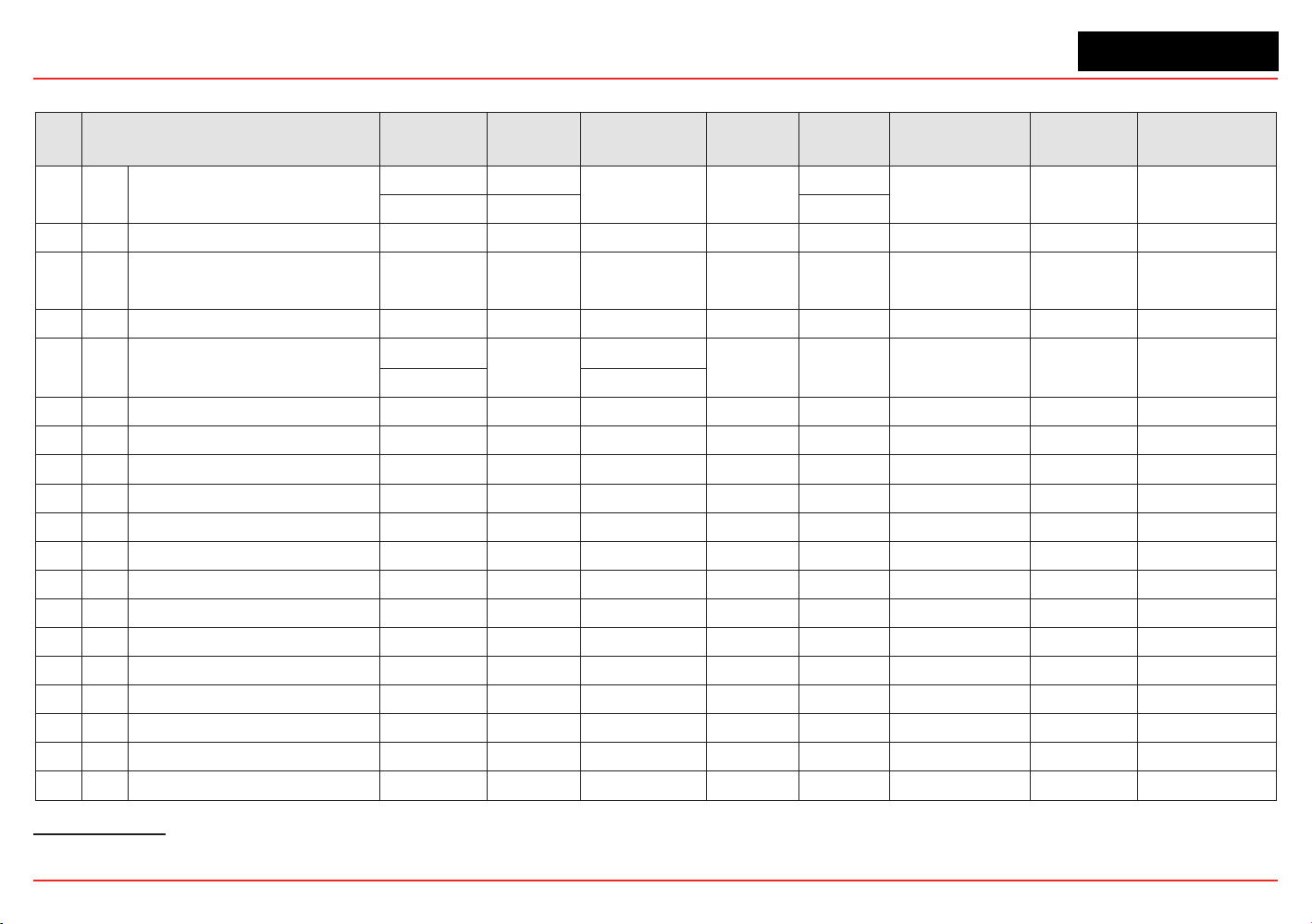
XNX Universal Transmitter
Section 6 - Specications
151
6.4.2 XNX EC Replacement Sensors
XNX
ID
Target Gas
Cartridge
Part No
Maximum
Range
Selectable
Range
Increment
Default
Range
Cal Gas Range Cal Gas P/N
Cal Gas
Description
1 O
2
Oxygen
XNXXS01SS 25.0 %Vol
N/A N/A
25.0 %Vol
20.9 %Vol N/A N/A
XNXXSO1FM 23.0% Vol 23.0% Vol
2 H
2
S Hydrogen Sulfide (Low Range) XNXXSH3SS 15.0 ppm N/A N/A 15.0 ppm 5.0 to 10.0 ppm GFV263 10 ppm H
2
S
3 H
2
S Hydrogen Sulfide
XNXXSH1SS
XNXXSH1FM
50.0 ppm 10.0 to 50.0 ppm 0.1 ppm 15.0 ppm 3 to 35 ppm GFV258 25 ppm H
2
S
4 H
2
S Hydrogen Sulfide (High Range) XNXXSH2SS 500 ppm 50 to 500 ppm 10 ppm 100 ppm 15 to 350 ppm GFV421 50 ppm H
2
S
5 CO Carbon Monoxide
XNXXSC1SS
1,000 ppm
100 to 500 ppm
100 ppm 300 ppm 30 to 200 ppm GFV295 100 ppm CO
XNXXSC1FM 100 to 1,000 ppm
6 SO
2
Sulfur Dioxide XNXXSS1SS 20.0 ppm 5.0 to 20.0 ppm 5.0 ppm 15.0 ppm 2 to 14 ppm Contact HA 7.5 ppm SO
2
7 SO
2
Sulfur Dioxide (High Range) XNXXSS2SS 50.0 ppm 20.0 to 50.0 ppm 10 ppm 50.0 ppm 6 to 35 ppm GFV441 25 ppm SO
2
8 NH
3
Ammonia XNXXSA1SS 200 ppm 50 to 200 ppm 50 ppm 200 ppm 150 to 140 ppm Contact HA 100 ppm NH
3
9 NH
3
Ammonia (High Range) XNXXSA2SS 1000 ppm 200 to 1,000 ppm 50 ppm 1,000 ppm 60 to 700 ppm Contact HA 300 ppm NH
3
10 Cl
2
Chlorine XNXXSL2SS 5.00 ppm N/A N/A 5.00 ppm 2 to 3 ppm GFV251 2 ppm Cl
2
in N
2
11 Cl
2
Chlorine (High Range) XNXXSL1SS 20.0 ppm 5.0 to 20.0 ppm 5.0 ppm 5.0 ppm 2 to 14 ppm GFV251 2 ppm Cl
2
in N
2
12 ClO
2
Chlorine Dioxide XNXXSX1SS 1.00 ppm N/A N/A 1.00 ppm 0.3 to 0.7 ppm Gas Generator 0.5 ppm
13 NO Nitrogen Monoxide XNXXSM1SS 100 ppm N/A N/A 100 ppm 30 to 70 ppm GFV216 50 ppm NO in N
2
14 NO
2
Nitrogen Dioxide XNXXSN1SS 50.0 ppm 5.0 to 50.0 ppm 5.0 ppm 10.0 ppm 2 to 35 ppm GFV435 5 ppm NO
2
15 H
2
Hydrogen XNXXSG1SS 1000 ppm N/A N/A 1,000 ppm 300 to 700 ppm GFV364 500 ppm H
2
16 H
2
Hydrogen (High Range) XNXXSG2SS 10,000 ppm N/A N/A 10,000 ppm 3,000 to 7,000 ppm Contact HA 5000 ppm H
2
in N
2
17 HCl Hydrogen Chloride XNXXSR1SS 20.0 ppm 10.0 to 20.0 ppm 1.0 ppm 10.0 ppm 4 to 12 ppm Contact HA 5 ppm HCl in N2
19 HF Hydrogen Fluoride XNXXSF1SS 12.0 ppm N/A N/A 12.0 ppm 4 to 8 ppm Contact HA 5 ppm HF in N
2
21 PH
3
Phosphine XNXXSP1SS 1.20 ppm N/A N/A 1.20 ppm 0.5 to 0.7 ppm GFV405 0.5 ppm PH
3
in N
2
1Indicatesagencyapprovalandportthreadspecication
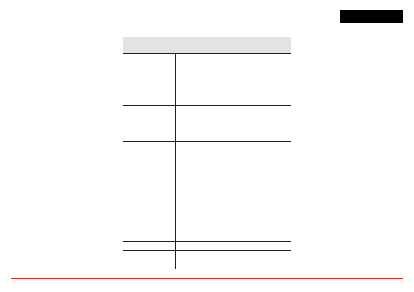
XNX Universal Transmitter
Section 6 - Specications
152
6.4.3 XNX EC Replacement Cells
Replacement
Cell P/N
Target Gas
Cartridge
Part No
S3KO1SS O
2
Oxygen
XNXXS01SS
XNXXSO1FM
S3KH1SS H
2
S Hydrogen Sulfide (Low Range) XNXXSH3SS
S3KH1SS
S3KH1SS
H
2
S Hydrogen Sulfide
XNXXSH1SS
XNXXSH1FM
S3KH2SS H
2
S Hydrogen Sulfide (High Range) XNXXSH2SS
S3KC1SS CO Carbon Monoxide
XNXXSC1SS
XNXXSC1FM
S3KS1SS SO
2
Sulfur Dioxide XNXXSS1SS
S3KS1SS SO
2
Sulfur Dioxide (High Range) XNXXSS2SS
S3KA1SS NH
3
Ammonia XNXXSA1SS
S3KA2SS NH
3
Ammonia (High Range) XNXXSA2SS
S3KL1SS Cl
2
Chlorine XNXXSL2SS
S3KL1SS Cl
2
Chlorine (High Range) XNXXSL1SS
S3KX1SS ClO
2
Chlorine Dioxide XNXXSX1SS
S3KM1SS NO Nitrogen Monoxide XNXXSM1SS
S3KN1SS NO
2
Nitrogen Dioxide XNXXSN1SS
S3KG1SS H
2
Hydrogen (Low Range) XNXXSG1SS
S3KG2SS H
2
Hydrogen (High Range) XNXXSG2SS
S3KR1SS HCl Hydrogen Chloride XNXXSR1SS
S3KY1SS HCN Hydrogen Cyanide XNXXSY1SS
S3KF1SS HF Hydrogen Fluoride XNXXSF1SS
S3KZ1SS O
3
Ozone XNXXSZ1SS
S3KP1SS PH
3
Phosphine XNXXSP1SS
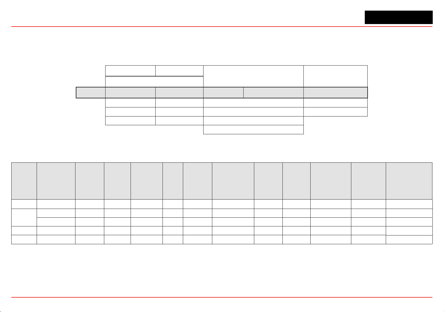
XNX Universal Transmitter
Section 6 - Specications
153
6.4.4 Multi Purpose Detector (MPD)
SimilartotheXNXTransmitter,theMPDpartnumberingsystemdenestheagencyapprovalandthreadtype.Theonlymaterialselection
isStainlessSteel.Foursensorselectionsareavailable.AgencyApprovalsarespecictothe4sensortypes.Ensuretheapprovalof
thespecicsensortypemeetstherequirementsoftheinstallation.
Model Type Port Cong
Installed Sensor Range
(See Section 6.2 for Agency Approvals)
MPD -
q q q q q
AM M25
CB - Catalytic Bead %LEL 1 - Default
UT 3/4” NPT
IF - IR %LEL Flammable 2 to 9 - Future
BT 3/4” NPT
IV - IR Methane 0-5% Vol
IC - R Carbon Dioxide 0-5% Vol
6.4.5 XNX Catalytic Bead and IR Replacement Sensor Cartridges
Sensor
Type
1, 2
Target Gas
Cartridge
Part No
Operating
Pressure
Range
(kPa)
Operating
Humidity
Range (%
RH non-
condensing)
Air
Speed
(m/s)
Maximum
Range
Selectable
Range
3
Increment
Default
Range
Cal Gas Range Cal Gas P/N
Cal Gas
Description
MPD-IC1 Carbon Dioxide 1226-0301 80 - 110 see footnote 4 0 - 6 5.00 %Vol 1.00 to 5.00 %Vol 1.00 %Vol 5.00 %Vol 1.50 to 3.5 %Vol
Contact HA
2.5 %VOL CO
2
in Air
MPD-IV1
Methane 1226-0299 80 - 110 0 - 95 0 - 6 5.00 %Vol 1.00 to 5.00 %Vol 1.00 %Vol 5.00 %Vol 1.50 to 3.5 %Vol GFV352 2.5 %VOL CH
4
in Air
Methane 1226-0299 80 - 110 0 - 95 0 - 6 100 %LEL 1.00 to 5.00 %Vol 1.00 %Vol 5.00 %Vol 1.50 to 3.5 %Vol GFV352 2.5 %VOL CH
4
in Air
MPD-IF1 Flammables 1226-0300 80 - 110 0 - 95 0 - 6 100 %LEL 20 to 100 %LEL
3
10 %LEL 100 %LEL 30 to 70 %LEL GFV406 1 %VOL C
3
H
8
in Air
MPD-CB1 Flammables 1226A0359 80 - 120 see footnote 5 0 - 6 100 %LEL 20 to 100 %LEL
3
10 %LEL 100 %LEL 30 to 70 %LEL GFV352 50 %LEL CH
4
in Air
1. Agency approved hydrogen sensors are MPD-CB1 and 705 STD.
2. When ordering replacement MPD sensor cartridges, the replacement cartridge must be the same type as factory congured. Substituting a different cartridge
will void agency certication.
3. On XNX %LEL units carrying UL/CSA certications, the range is xed at 100%LEL and is not adjustable.
4. Humidity: 5% to 95% RH non-condensing
5. Humidity: 0 to 99% RH non-condensing
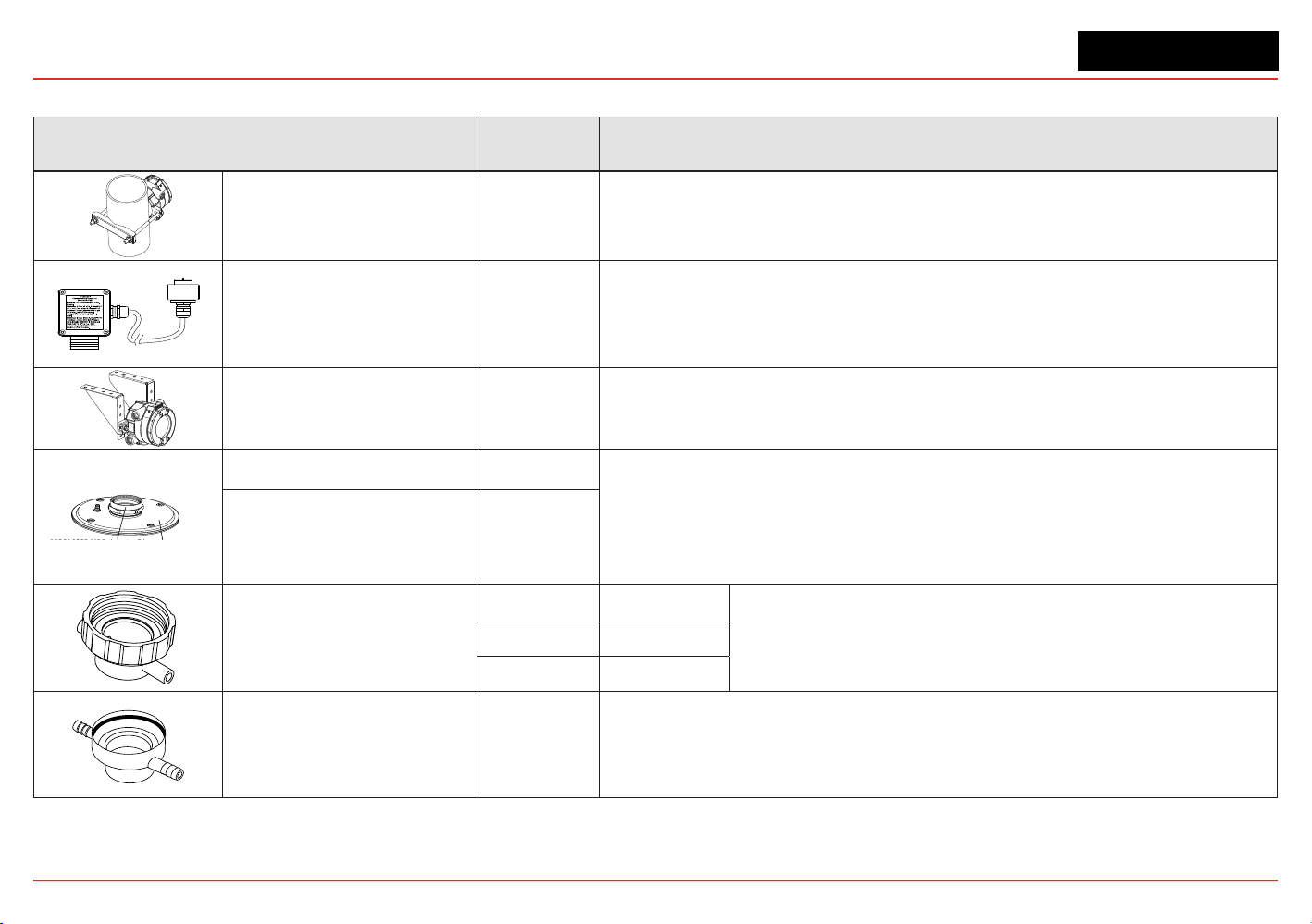
XNX Universal Transmitter
Section 6 - Specications
154
6.4.6 Accessories/Spares
Accessory/Spare Part Number Description
PipeMountKit 1226A0358
Foruseonpipesfrom2-6inches(50-150mm)indiameter.
Kitincludes:PipeMountBracket,(2)CarriageBolts,NutsandLockWashers.
RemoteECSensorMounting
Kit
S3KRMK
Theremotesensormountingkit(S3KRMK)allowstheXNXECsensorstoberemotely
mountedviaanIScablekit,upto50feet(15meters)fromthetransmitter.Thekitincludes
50feetofshieldedcable,cableglandsandremoteterminalbox.Thecablecanbecut
totherequiredlengthandterminatedattheremoteterminalbox.
CeilingMountBracketKit 1226A0355
TheoptionalCeilingMountBracketKitallowstheXNXtobemountedtotheceiling.
Kitincludes:(2)StainlessSteelCeilingMountBrackets,boltsandnuts.
1226A0382 MPD Adapter Ring
S3KDMK EC/MPD Duct Adapter Kit
DuctMountKit S3KDMK
Theductmountingkit(S3KDMK)canbeusedwiththeECsensortoallowdetectionof
O2,CO,H2andH2Sgasesinducts.
WhencombinedwiththeMPDInterfaceAdapter(1226A0382),theductmountingkitcan
accommodatetheMPDtodetectammablegasesinaductapplication.Theductmount
kit includes theadapter, gasket and required fasteners. The MPD Interface Adapter
includesonlytheadapterandrequirestheS3KDMKductmountkit.
MPDInterfaceAdapter 1226A0382
CalibrationGasFlowAdapter
1226A0411 MPD
02000-A-1645
SensepointHT
00780-A-0035 705
Calibration Cup S3KCAL
XNXEC-Thecalibrationcupisusedtoapplycalibrationtestgastothesensor.Itpushts
ontothebottomofthesensorandcanbettedwithoutremovingtheweatherproofcover.
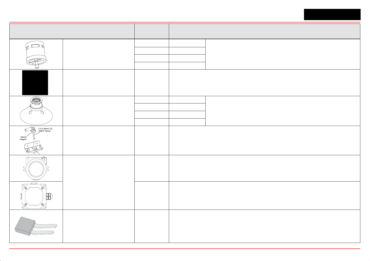
XNX Universal Transmitter
Section 6 - Specications
155
Accessory/Spare Part Number Description
Weatherproof Cap
Included XNXEC
TheweatherproofcapprotectstheXNXsensorsfromharshweather.
02000-A-1640 MPD
02000-A-1640 Sensepoint
02000-A-1635 705
ExtremeWeatherProtector SPXCDWP
SensorXNX-ECorMPD;theweatherprotectionisdesignedtoprotectthesensorfrom
environmentalconditionsinoutdoorexposureapplications.
Collecting Cone
S3KCC XNXEC
The collecting cone improves detection of lighter-than-air gases such
as hydrogen and methane.
02000-A-1642 MPD
02000-A-1642 Sensepoint
02000-A-1642 705
RemoteGassingKit 1226A0354
TheRemoteGassingKitenablesgastobeappliedremotelyforperformingfunctional
responsechecks.
KitIncludes:50’Teon
®
tubing,mountingbracket,tubecapanddeviceadaptersin1/4”
and1/8”IDtoattachtobumptestportsontheweatherproofcapofyourdevice.
RemoteMPDMounting
2441-0022 UL/CSAAluminumJunctionBox
00780-A0100 ATEX/IECJunctionBox(3)M20,(1)M25entries.“Exe”ATEXIECApproval
TerminalBlock/Shorting
Jumpers
ContactHA
Terminal block jumpers provide an electrical connection without connection to the
PersonalityBoard.Installthejumpersbetweenpins1and2andbetweenpins3and4
tosupportmulti-nodewiring.
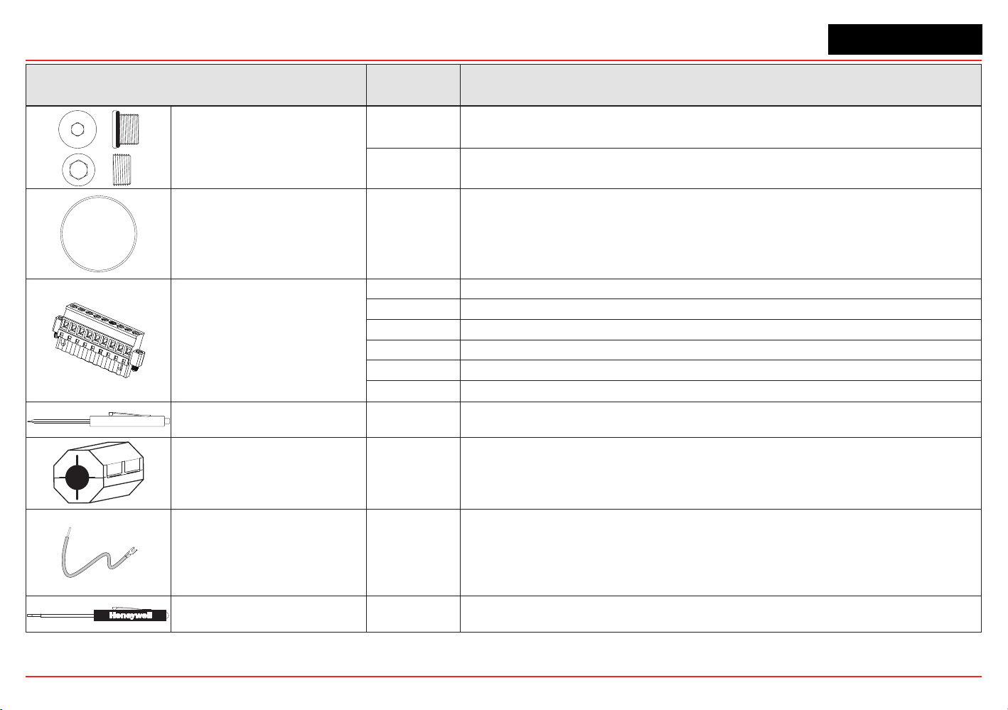
XNX Universal Transmitter
Section 6 - Specications
156
Accessory/Spare Part Number Description
Stopping Plugs
1226-0257
M25Plugw/protectivecapandO-ring.(CertiedforusewithXNXUniversalTransmitter
only)
1226-0258 3/4NPTw/protectivecap.(CertiedforusewithXNXUniversalTransmitteronly)
Replacement Cover O-ring 0235-1266 Replacement O-ring for the XNX front cover
1
2
3
4
5
6
7
8
9
Pluggable TerminalBlocks
1226A0302 TerminalBlockAss’y6-PinXNXEC
1226A0304 TerminalBlockAss’y9-PinXNXmV
1226A0305 IRTerminalBlockKitIncludes:9-Pinand2-PinTerminalBlocks
1226A0306 RelayTerminalBlockKitIncludes:9-Pinand2-PinTerminalBlocks
1226A0307 TerminalBlockAss’y10-PinXNXModbus
1226A0303 TerminalBlockAss’y6-PinFFB
MagneticWand/Screwdriver 1226-0254 Replacementwandforfrontpanelaccess
Ferrite Bead 0060-1051 Bead Ferrite MV XNX
FoundationFieldbusGround
Cable
0310-0041 CableGroundFoundationFieldbusXNX
Small Screwdriver 1226-0408
ReplacementscrewdriverforuseonTerminalBlockTB2andTB4(IRPersonalityand
RelayOption)
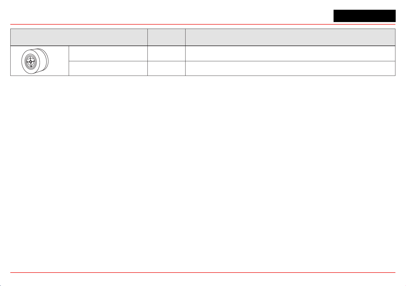
XNX Universal Transmitter
Section 6 - Specications
157
Accessory/Spare Part Number Description
WeatherHousing 0200-A-1635 ForusewithSeries2000,SensePoint,andSignalPointEECSensorProducts
WeatherHousing 0200-A-1640 ForusewithSeries2000,SensePoint,andSignalPointCombustibleSensorProducts

XNX Universal Transmitter
XNX Universal Transmitter Technical Manual
159
7 Control Drawings
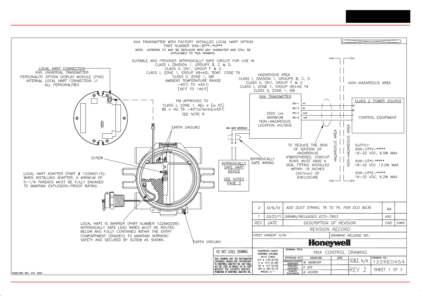
XNX Universal Transmitter
Section 7 - Control Drawings
159
7.1 XNX UL/INMETRO
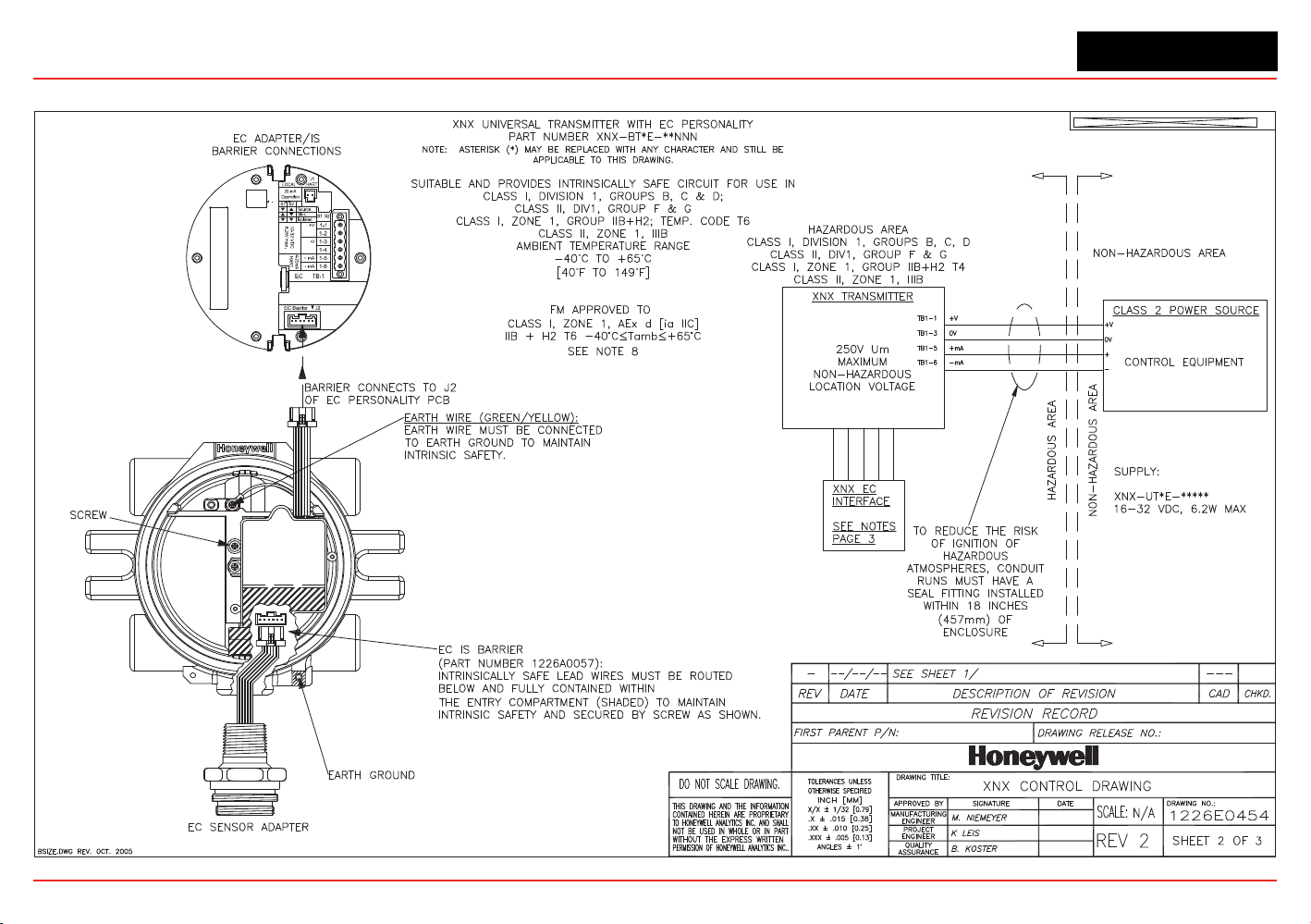
XNX Universal Transmitter
Section 7 - Control Drawings
160

XNX Universal Transmitter
Section 7 - Control Drawings
161
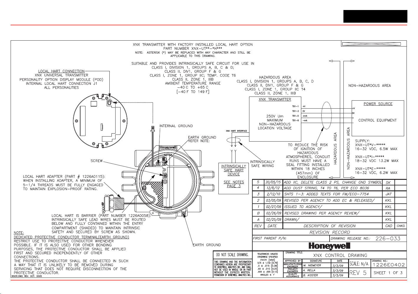
XNX Universal Transmitter
Control Drawings
XNX UL/CSA/FM
˚ ˚
˚ ˚
162
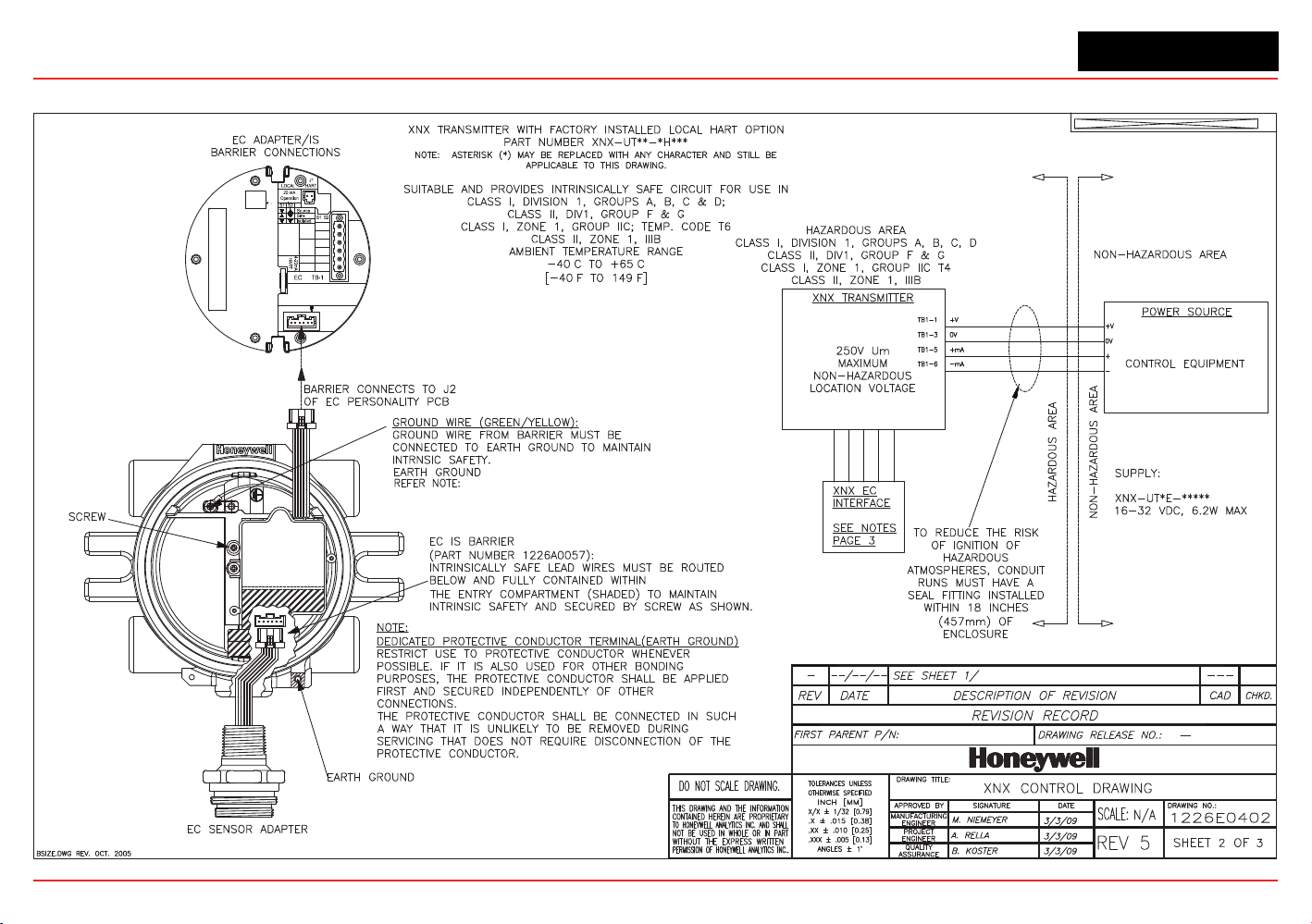
XNX Universal Transmitter
Control Drawings
18-32 VDC
6.2W max.
1-1
1-2
1-3
1-4
1-5
1-6
EC Barrier J2
+V
-V
+ mA
- mA
˚ ˚
˚ ˚
163
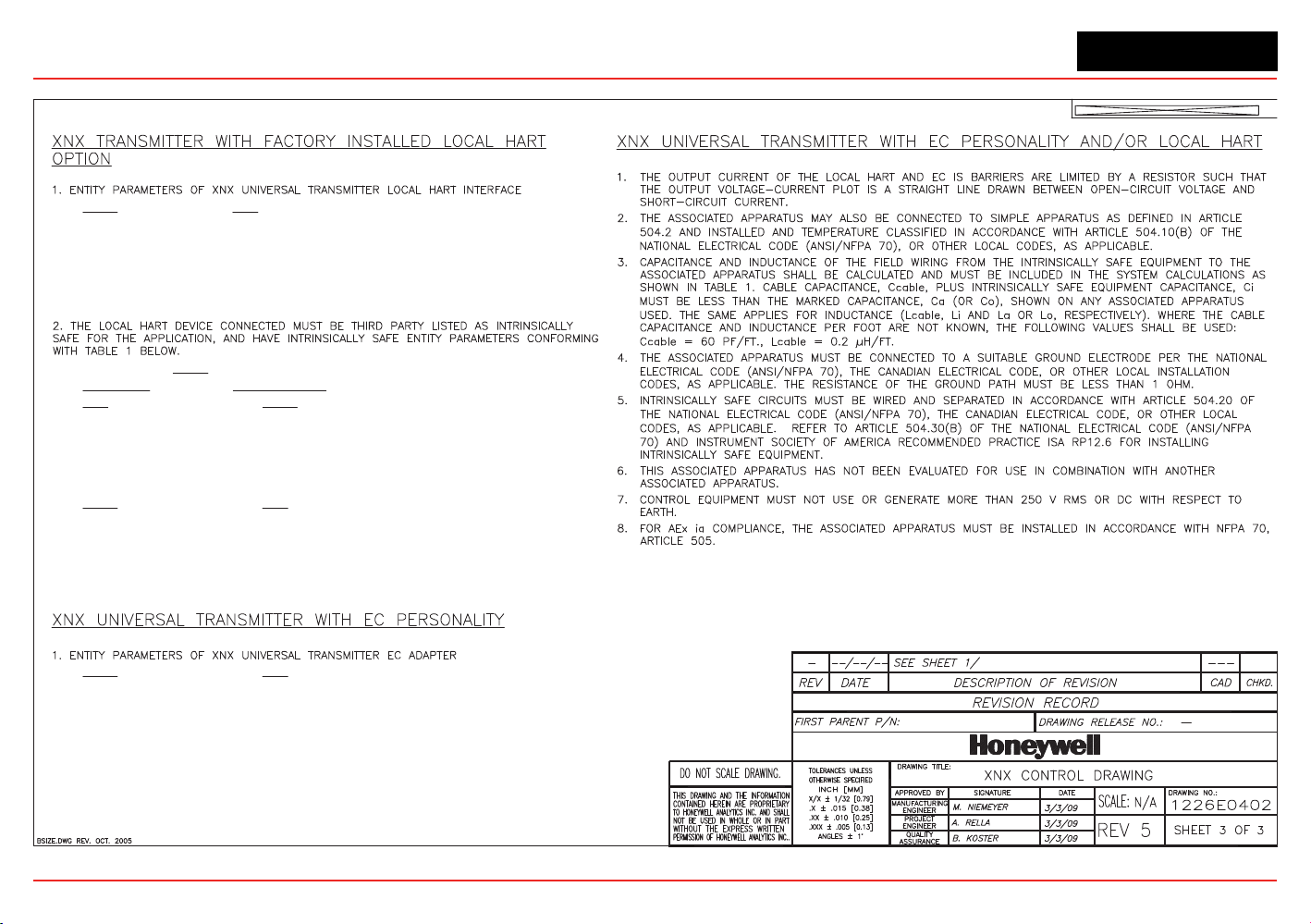
XNX Universal Transmitter
Control Drawings
OUTPUT INPUT
Uo = 24.15V Ui = 21.85V
Io = 136mA Ii = 120mA
Po = 0.82W Pi = 1.0W
Lo = 1.4mH Li = 0.0mH
Co = 0.122uF Ci = 0.0uF
TABLE 1
IS HART DEVICE XNX HART INTERFACE
INPUT OUTPUT
V max (or Ui)
Voc or Vt (or Uo)
I max (or Ii)
Isc or It (or Io)
P max, Pi
Po
Ci + Ccable
Ca (or Co)
Li + Lcable
La (or Lo)
OUTPUT INPUT
Voc or Vt (or Uo)
V max (or Ui)
Isc or It (or Io)
I max (or Ii)
Po
P max, Pi
Ca (or Co)
Ci + Ccable
La (or Lo)
Li + Lcable
OUTPUT INPUT
Voc or Vt (or Uo) = 5.88 V
V max (or Ui)
Isc or It (or Io) = 84 mA
I max (or Ii)
Po = 123 mW
P max, Pi
Ca (or Co) = 10uF
Ci + Ccable
La (or Lo) = 1 mH
Li + Lcable
164
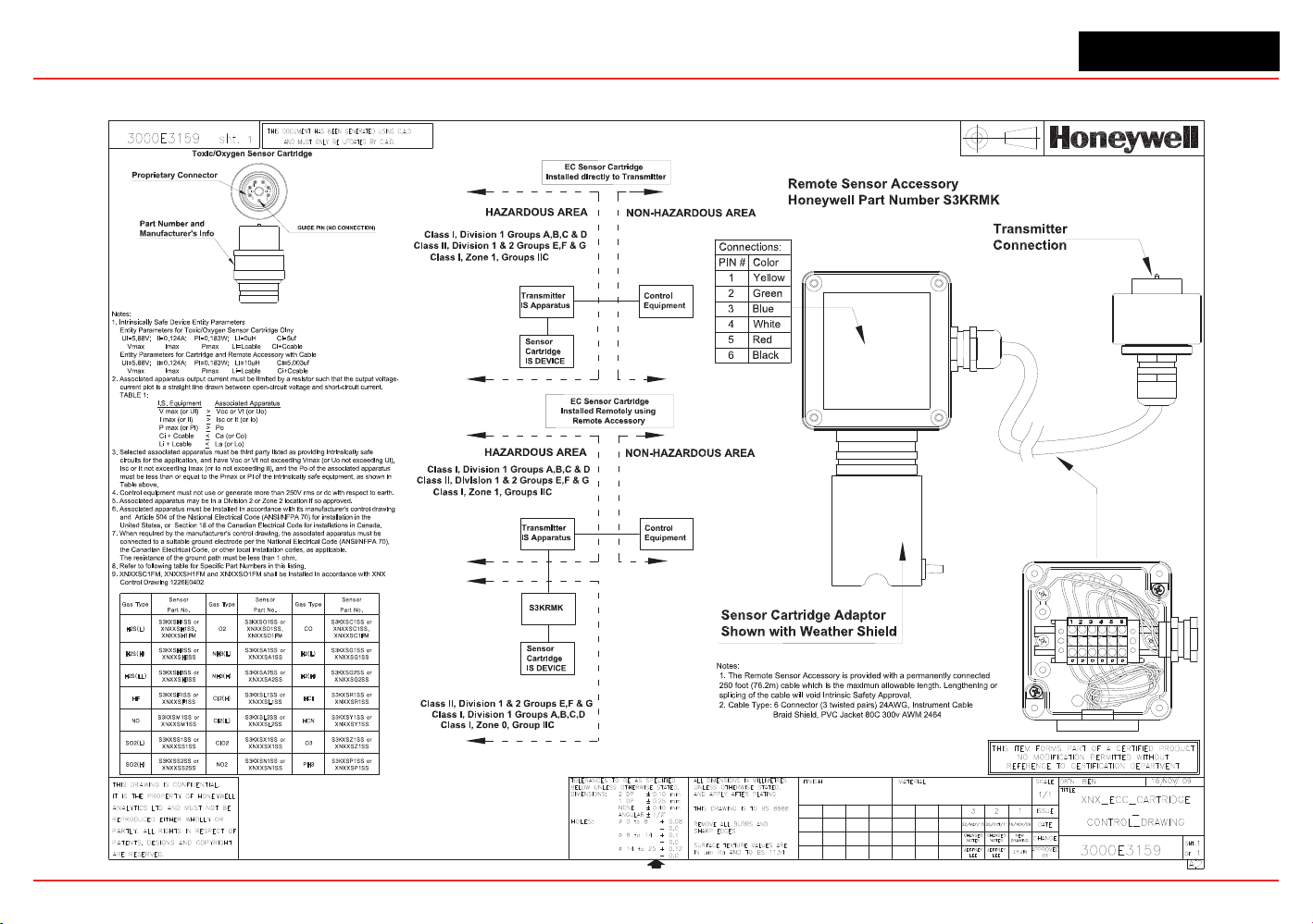
XNX Universal Transmitter
Control Drawings
Remote Sensor Mount
Sens or Se ns or Se ns or
Par t No. Part No. Part No.
S3KXSC1SS or
XNX X SC1SS,
XNX X SC 1FM
CO
NH3(H)
PH3
S3KXSP1SS or
XNXX SP1SS
HCN
S3KXSY1SS or
XNXX SY1SS
S3KXSZ1SS or
XNXX SZ1SS
S3KXSL2SS or
XNXX SL2SS
Cl2(L )
SO2(H)
S3KXSS2SS or
XNXX SS2SS
NO2
S3KXSN1SS or
XNXX SN1SS
SO2(L)
S3KXSS1SS or
XNXX SS1SS
S3KXSX1SS or
XNXX SX1SS
O3ClO2
NO
S3KXSM1SS or
XNXX SM1SS
HF
S3KXSF1SS or
XNXX SF1SS
S3KXSL1SS or
XNXX SL1SS
HCl
S3KXSR1SS or
XNXX SR1SS
S3KXSA2SS or
XNXX SA2SS
H2(H)
S3KXSG2SS or
XNXX SG2SS
H2S(L L)
S3KXSH3SS or
XNXX SH3S S
H2S(H)
S3KXSH1SS or
XNX X SH1SS,
XNX X SH1FM
S3KXSH2SS or
XNXX SH2S S
Cl2(H)
S3KXSG1SS or
XNXX SG1SS
Gas Type Gas Type Gas Type
O2
S3KXSO1SS or
XNX X SO1SS,
XNXX SO1FM
NH3(L)
S3KXSA1SS or
XNXX SA1SS
H2(L)
H2S(L )
165

XNX Universal Transmitter
XNX Universal Transmitter Technical Manual
167
Appendix A - HART
®
Protocol
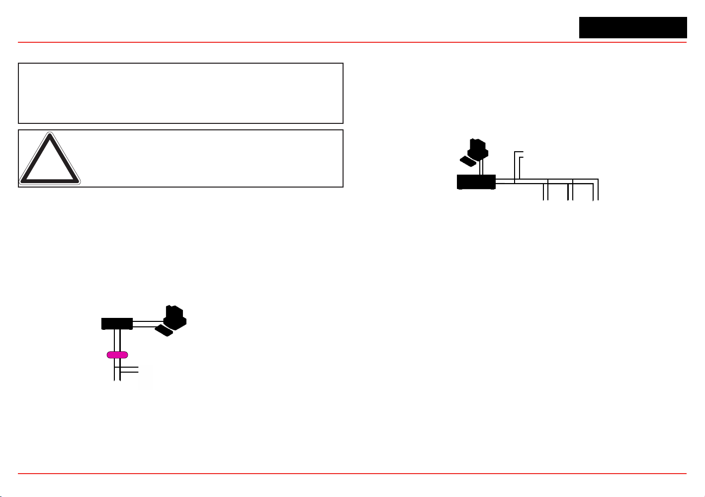
XNX Universal Transmitter
Appendix A - HART
®
Protocol
167
A.1 HART
®
Interface
The XNX Universal Transmitter is registered with the
HART Communication Foundation.
Note: Only qualified service personel should perform the procedures in this section.
Every XNX
®
gas sensor can communicate using the HART protocol
(dened by the HART Communication Foundation at http://www.
hartcomm.org). HART is unique among eldbuses in that the digital
signal is superimposed on a traditional 4-20 mA current loop. This
provides the reliability of analog signaling with the advanced
diagnostic capability of a digital device.
HART devices are usually connected as point-to-point networks. The
analog output of the XNX transmitter can also be disabled to facilitate
construction of multidrop, all-digital HART networks.
Control System
or Other Host Application
Multiplexer
Barrier
Handheld Terminal
Field Device
Note: Instrument power is provided by an interface
or external power source that is not shown.
Figure 233. HART Point-to-point Mode
If HART is not needed, the unit can be used as a 4-20 mA transmitter.
Since the transmitter is a slave, the internal modem will remain silent
if no master signal is present. Additionally the HART signal is at too
high a frequency (1200 Hz) to interfere with analog control equipment.
Another novel feature of HART networks is that two masters can
be present. The primary master is usually a distributed control
system (DCS), programmable logic controller (PLC), or a personal
computer (PC). The secondary master can be a handheld terminal.
The XNX transmitter has been tested with the handheld Emerson eld
communicator.
Input/Output (I/O) System
Handheld Terminal
Field Devices
Control System or
Other Host Application
Note: Instrument power is provided by an interface
or external power source that is not shown.
Figure 234. HART Multi-point Mode
The XNX device descriptor (DD) le provides HART users with data
on the capabilities and features of the XNX Universal Transmitter.
Select HART enabled devices are able to interface with XNX
transmitters when connected via HART communication. A copy of
the le is included on the Documentation CD. This DD le can be
installed on HART-enabled Emerson eld communicators using the
Emerson Easy Upgrade Utility. The DD les located on the resource
CD are compatible with the software integral to the transmitter. Older
transmitters using earlier versions of software require previous versions
of the DD les. Contact your local Honeywell representative with any
questions regarding software compatibility.
During manufacturing, Honeywell congures the 8-digit HART tag to
the XNX serial number. This can be used to conrm correct wiring
from the transmitter to the control system. If desired, the HART tag
can be modied. The xed XNX serial number can also be read over
HART.
For convenience, the transmitter presents the HART signal on two
interfaces. The 1200 Hz AC signal is capacitively coupled to the main
20 mA analog output. This may be monitored at the control system
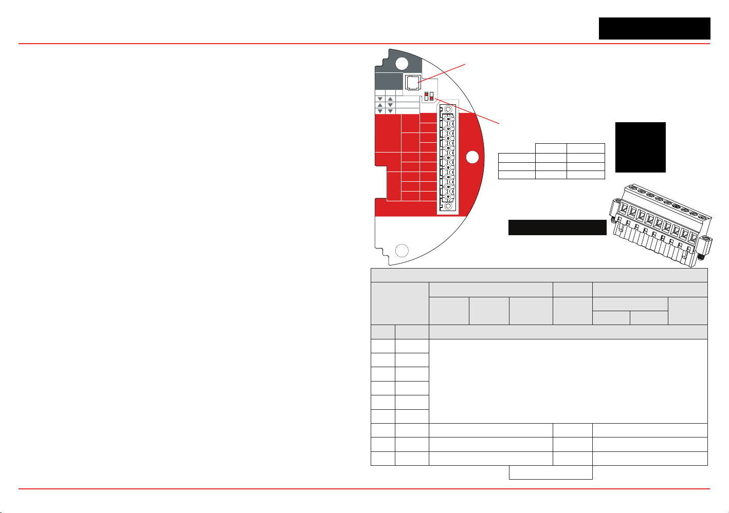
XNX Universal Transmitter
Appendix A - HART
®
Protocol
168
or at any point along the 20 mA loop. Additionally, the optional local
HART interface (P/N: XNX-HIF) permits temporary connection of a
HART terminal to the transmitter. This local HART port is transformer-
coupled to the main 20 mA output. This port is intrinsically safe and
polarity insensitive. See Section 2.3.1 for more information.
The internal HART modem functions as a high-impedance current
source. Thus transferring the HART signal requires a certain minimum
loop resistance between the slave and a low-impedance power
supply.
Normally, this resistance is supplied by the control system and so
need not be explicitly added. However, special treatment is needed
when the 20 mA output is not used and the local HART interface is
needed. (An installer might choose to communicate using relays,
Modbus
®
, or Foundation
TM
Fieldbus instead.) In this case, the
supplied 510 ohm resistor must be tted to create an “articial” 20
mA loop. The resistor should be connected between TB-1 terminal
1-3 and terminal 1-6. Additionally, S1 and S2 should be placed in
“source” conguration. This is shown schematically in Figure 237.
The digital HART interface provides all of the capabilities of the local
user interface. The XNX transmitter has been designed to use the
portable Emerson eld communicator with DevCom2000 software for
Microsoft Windows
®
and Emerson AMS Intelligent Device Manager.
Using HART, a service person can display information, test, calibrate,
and congure. A map of the HART menus is provided in Section
A.1.3.
ATEX Conditions for Safe Use of Intrinsically Safe
HART Handheld Devices
For installations in which both the Ci and li of the intrinsically safe
apparatus exceeds 1% of the Co and lo parameters of the associated
apparatus (excluding the cable), 50% of Co and lo parameters are
applicable and shall not be exceeded, i.e., the Ci of the device plus
the C of the cable must be less than or equal to 50% of the Co of
the associated apparatus, and the li of the device plus the l of the
cable must be less than or equal to 50% of the lo of the associated
apparatus.
Figure 235. XNX mV Personality
Board Terminal Blocks, Jumper Switches
and Wire Color Chart
HART
20 mA
Operation
LOCAL
J1
S1
+V 1-1
mV TB-1
MPD, 705
Sensepoint
4-20mA
HART
16-32 VDC
6.5W max.
1-2
-V 1-3
1-4
+mA 1-5
-mA 1-6
Sense
1-7
0v 1-8
Ref 1-9
S1
Source
Sink
Isolated
S2
S2
XNX mV TB-1
▼▼
S2S1
▼▼
Isolated
▲
Sink
▼
Source
J1 - Local HART Option Connector
S1 and S2 - 20mA Output
Jumper Switch
▼
▲
mV Sensor Type
Catalytic Bead MPD w/IR
MPD
705
705HT
S’point
S’point HT
S’point
PPM
IR 5%
IR Flam
CO
2
CH
4
TB-1 Desc. Wire Color from Sensor
1 24v
See Section 2.2.4.
2
3 Gnd
4
5 20mA +
6 20mA -
7 Sense Brown Red Brown
8 0v White Green White
9 Ref Blue Blue Blue
Internal Ground
1
2
3
4
5
6
7
8
9
510 Ohm Resistor
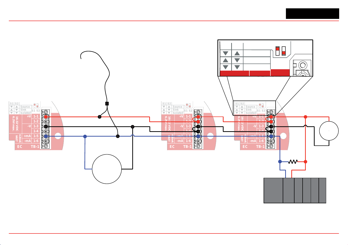
XNX Universal Transmitter
Appendix A - HART
®
Protocol
169
A.1.1 HART Sink, Source, and Isolated Wiring
The following gures illustrate the proper HART Multidrop wiring for the XNX.
S1
S1
Source
Sink
Isolated
S2
S2
+V 1-1
EC TB-1
4-20mA
HART
16-32 VDC
6.2W max.
1-2
-V 1-3
1-4
+mA 1-5
-mA 1-6
S1
S1
Source
Sink
Isolated
S2
S2
+V 1-1
EC TB-1
4-20mA
HART
16-32 VDC
6.2W max.
1-2
-V 1-3
1-4
+mA 1-5
-mA 1-6
S1
S1
Source
Sink
Isolated
S2
S2
+V 1-1
EC TB-1
4-20mA
HART
16-32 VDC
6.2W max.
1-2
-V 1-3
1-4
+mA 1-5
-mA 1-6
250 Ω
minimum
XNX
Address 1
XNX
Address 2
XNX
Address 7
HART
Handheld
Communicator
NOTE: Only addresses greater than 0 are valid for multidrop HART networks.
Other loop
powered
HART
devices
-
+
S1
S1
Source
Sink
Isolated
S2
S2
+V 1-1
1
6.
+
24
VDC
-
External HART
Automation Equipment
Figure 236. XNX Multidrop HART Network Wiring - XNX Sink
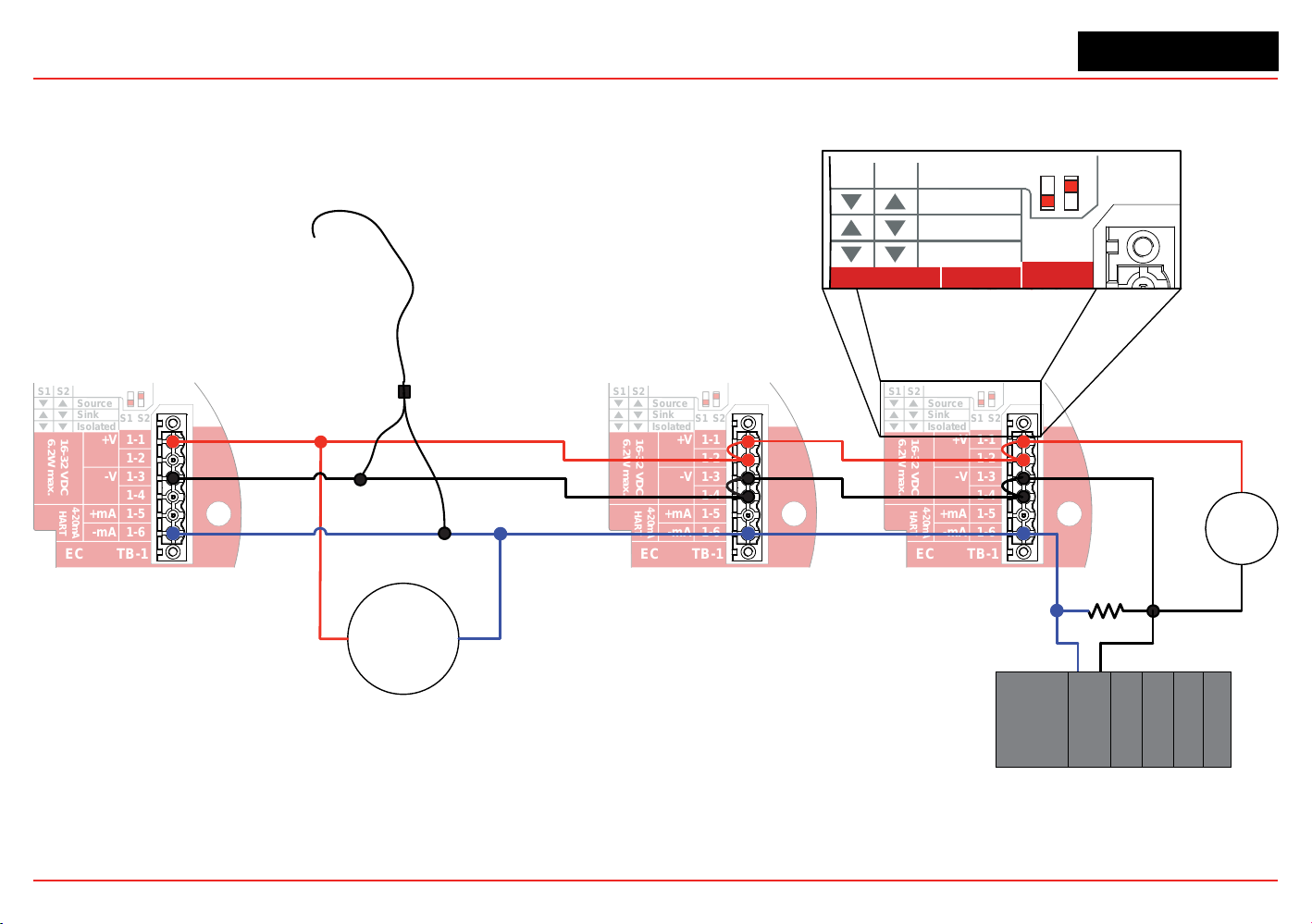
XNX Universal Transmitter
Appendix A - HART
®
Protocol
170
Figure 237. XNX Multidrop HART Network Wiring - XNX Source
S1
S1
Source
Sink
Isolated
S2
S2
+V 1-1
EC TB-1
4-20mA
HART
16-32 VDC
6.2W max.
1-2
-V 1-3
1-4
+mA 1-5
-mA 1-6
S1
S1
Source
Sink
Isolated
S2
S2
+V 1-1
EC TB-1
4-20mA
HART
16-32 VDC
6.2W max.
1-2
-V 1-3
1-4
+mA 1-5
-mA 1-6
S1
S1
Source
Sink
Isolated
S2
S2
+V 1-1
EC TB-1
4-20mA
HART
16-32 VDC
6.2W max.
1-2
-V 1-3
1-4
+mA 1-5
-mA 1-6
250 Ω
minimum
XNX
Address 1
XNX
Address 2
XNX
Address 7
Emerson
Field Communicator
NOTE: Only addresses greater than 0 are valid for multidrop HART networks.
Other loop
powered
HART
devices
-
+
S1
S1
Source
Sink
Isolated
S2
S2
+V 1-1
1
6.
+
24
VDC
-
External HART
Automation Equipment
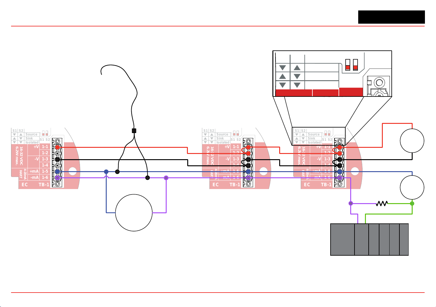
XNX Universal Transmitter
Appendix A - HART
®
Protocol
171
S1
S1
Source
Sink
Isolated
S2
S2
+V 1-1
EC TB-1
4-20mA
HART
16-32 VDC
6.2W max.
1-2
-V 1-3
1-4
+mA 1-5
-mA 1-6
S1
S1
Source
Sink
Isolated
S2
S2
+V 1-1
EC TB-1
4-20mA
HART
16-32 VDC
6.2W max.
1-2
-V 1-3
1-4
+mA 1-5
-mA 1-6
S1
S1
Source
Sink
Isolated
S2
S2
+V 1-1
EC TB-1
4-20mA
HART
16-32 VDC
6.2W max.
1-2
-V 1-3
1-4
+mA 1-5
-mA 1-6
250 Ω
minimum
XNX
Address 1
XNX
Address 2
XNX
Address 7
HART
Handheld
Communicator
NOTE: Only addresses greater than 0 are v
alid for multidrop HART networks.
Other loop
powered
HART
devices
-
+
S1
S1
Source
Sink
Isolated
S2
S2
+V 1-1
1
6.
External HART
Automation Equipment
+
24
VDC
-
+
24
VDC
-
Figure 238. XNX Multidrop HART Network Wiring - Isolated
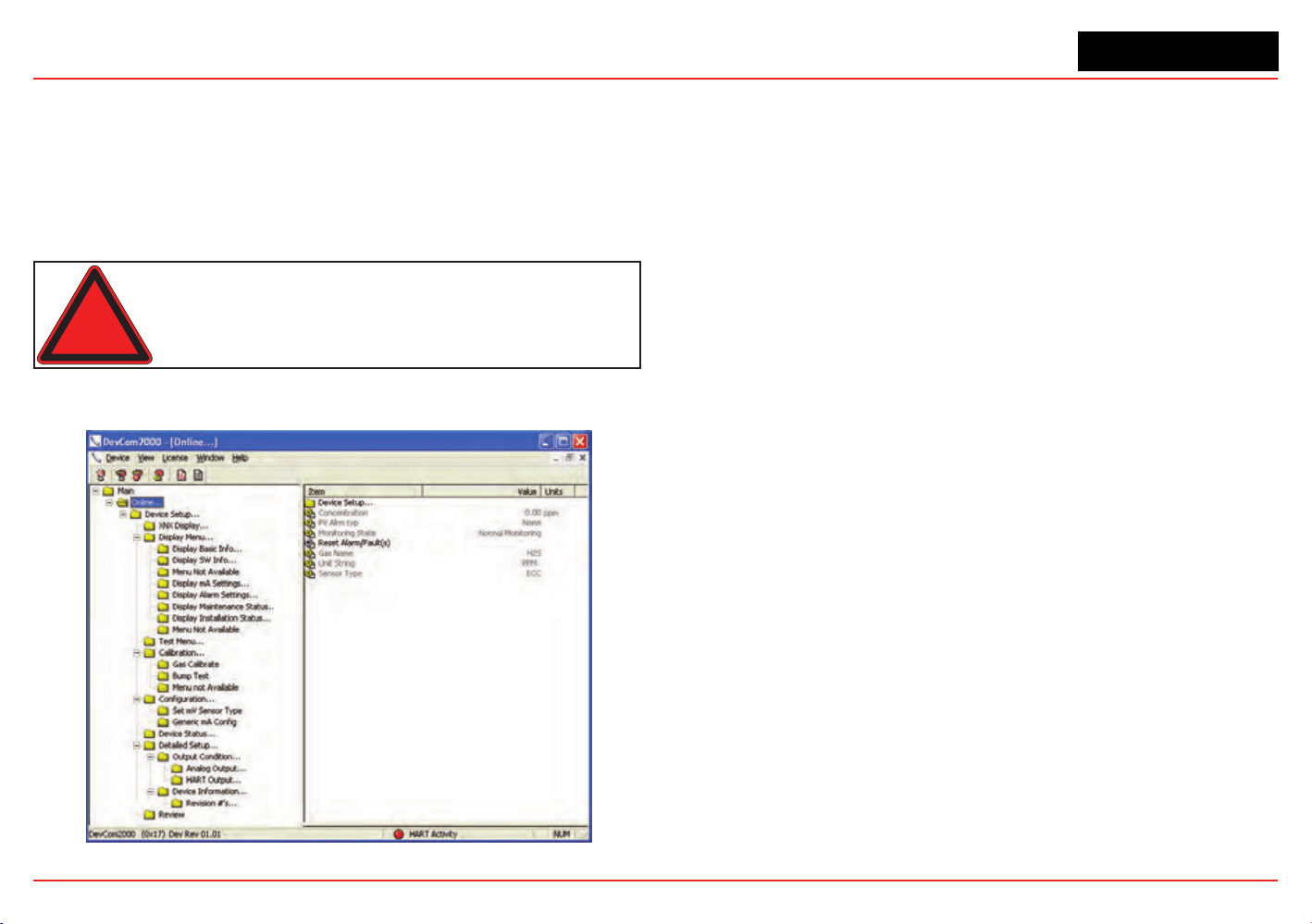
XNX Universal Transmitter
Appendix A - HART
®
Protocol
172
A.1.2 DevComm PC-based HART Interface
Overview
The XNX-HART interface facilitates remote access to all features
of the local user interface including displaying status, testing,
calibrating, and conguring. A device descriptor (DD) le is
available to adapt standard tools for use with the transmitter.
Warning: After changing parameters with a handheld device,
verify that the parameter settings are correct at the transmitter.
The following screens show some of the features of these two
interfaces for the XNX transmitter.
Figure 239. Presentation of XNX Data by DevComm2000
Figure240.XNXdatadisplayedonanEmersoneldcommunicator
Security level 1 is required to select the display language and to
adjust the date and time. All other conguration options require
security level 2 access.
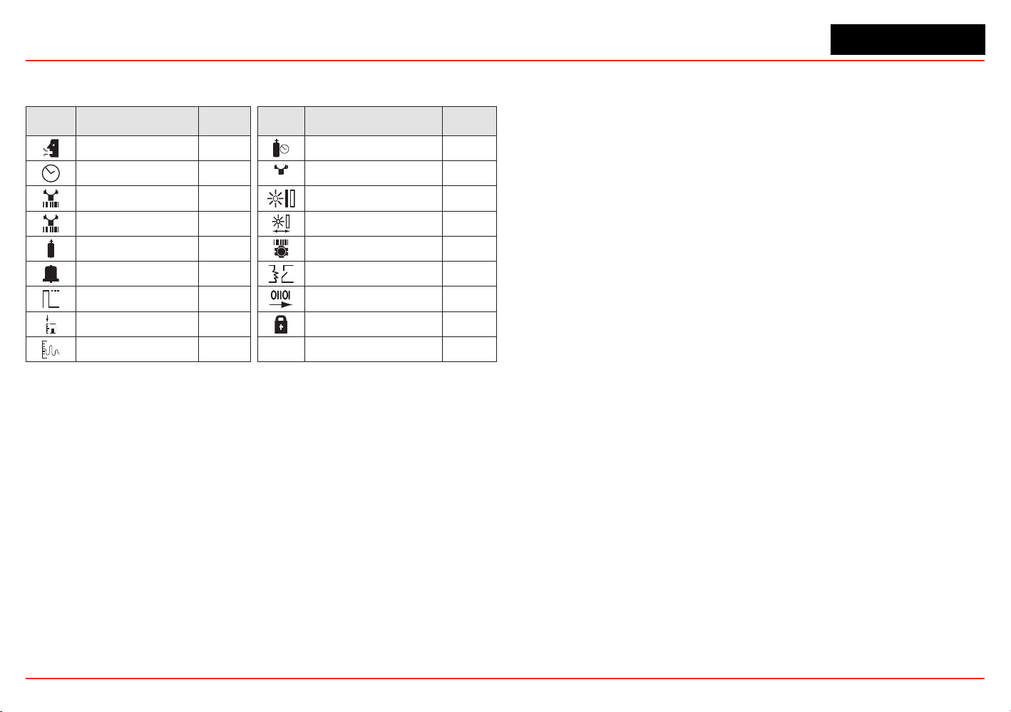
XNX Universal Transmitter
Appendix A - HART
®
Protocol
173
Functions in the Congure Menu and the security levels required
to change them are explained in this table.
Symbol Description
Security
Level
Symbol Description
Security
Level
Select Language 1 Calibration Interval 2
Set Date & Time 1
✓
Accept New Sensor
Type
2
Set mV Sensor Type 2 Beam Block Options 2
Set mA Sensor Type 2 Path Length 2
Gas Selection 2 Unit ID 2
Range & Alarms 2 Relay Options 2
Latching/Non-
latching
2 Fieldbus Options 2
Set Units 2 Congure Security 2
mA Levels 2
Functions
Conguration Summary
All of the HART status information can be extracted from the
transmitter as a PDF or text le. This includes voltages, signal
strengths, and conguration settings. An example summary,
which required only 5 mouse clicks, is shown below.
Figure 241. HART status information
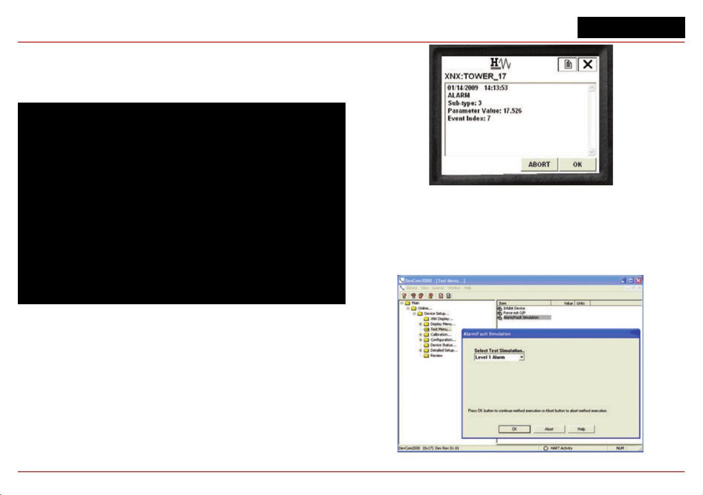
XNX Universal Transmitter
Appendix A - HART
®
Protocol
174
Information Screens
All of the information in the Conguration Summary can be
viewed live on various informational displays. For example,
alarm settings are shown in Figure 242.
Figure 242. Typical Alarm Settings Display
Event History
The XNX transmitter maintains a record of all signicant events.
All alarms, all warnings, and all faults are recorded. Additionally,
over sixty types of informational events are dened to record
important transactions such as recalibrations or conguration
changes. One-thousand records are maintained and every event
has a timestamp.
Figure 243. HART Event History Display
Test
The test menu provides methods for inhibiting the output,
exercising the analog output, or simulating alarms or faults.
These methods simplify common tasks by providing a simple
user interface.
Figure 244. Alarm Simulation
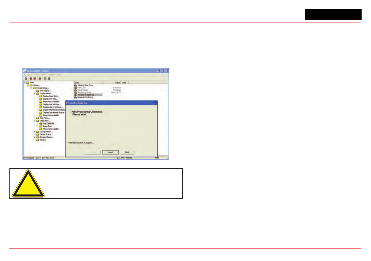
XNX Universal Transmitter
Appendix A - HART
®
Protocol
175
Calibration
The calibration menu permits calibrating zero or span and
bump testing. Additionally, when tted with a Searchline EXCEL
sensor, the Calibrate menu displays the optical signal strength
for mechanical alignment. The gas calibrate operation is shown
below.
Figure 245. Gas Calibrate Method
Caution: Do not back out of a menu selection while a calibration is in progress.
Conguration
All user settings of the XNX transmitter can be made either at
the local user interface or over HART. The conguration menu
facilitates convenient setup of alarm levels as shown in Figure
246. Methods are also provided to set time, units, and other
parameters.
Figure 246. Set Range and Alarm
Conclusion
The XNX HART interface adds value by facilitating remote
operation of Honeywell Analytics gas sensors. All functions
available locally are also available over HART.

XNX Universal Transmitter
Appendix A - HART
®
Protocol
176
A.1.3 Handheld Online Menu
When HART communication is established with the XNX, the Root menu is displayed:
Main Menu Key Sub Menus
Online...
1 Device Setup
2 Concentration 0.00
%LEL
3 PV Alrm Typ
4 Monitoring State Normal Monitoring
5 Reset Alarm Fault(s) None
6 Gas Name Methane
7 Sensor Type Optima
Device Setup...
1 User Login
2 XNX Display...
3 Display Menu...
4 Test Menu...
5 Calibration...
6 Configuration...
7 Device Status...
8 Detailed Setup...
9 Review
Current Login Level: Default
Want to change Login Level
1 Logout [Level 0]
2 Login [level1/2/3]
3 Exit
Online...
1 Device Setup
2 Concentration 0.00
%LEL
3 PV Alrm Typ
4 Monitoring State Normal Monitoring
5 Reset Alarm Fault(s) None
6 Gas Name Methane
7 Sensor Type Optima
Device Setup...
1 User Login
2 XNX Display...
3 Display Menu...
4 Test Menu...
5 Calibration...
6 Configuration...
7 Device Status...
8 Detailed Setup...
9 Review
XNX Display...
1 Concentration 0.00 %LEL
2 PV Alrm Typ None
3 Fault/Warn Number F
4 Monitoring State Normal Monitoring
5 Time Date Format mm/dd/yy hh:mm:ss
6 Time Date Stamp 09/18/08 11:57:57
7 Gas Name Methane LEL
Online...
1 Device Setup
2 Concentration 0.00
%LEL
3 PV Alrm Typ
4 Monitoring State Normal Monitoring
5 Reset Alarm Fault(s) None
6 Gas Name Methane
7 Sensor Type Optima
Device Setup...
1 User Login
2 XNX Display...
3 Display Menu...
4 Test Menu...
5 Calibration...
6 Configuration...
7 Device Status...
8 Detailed Setup...
9 Review
Display Menu...
1 Reset Alarm Faults
2 Event History
3 Display Basic Info...
4 Display SW Info...
5 Display Optical Performance
6 Display mA Settings
7 Display Alarm Settings
8 Display Maintenance Status
9 Display Installation Status
Display Basic Info...
1 Gas Name
Methane LEL
2 XNX ID SOUTH
TOWER
XNX HART Basic Menus (cont’d)

XNX Universal Transmitter
Appendix A - HART
®
Protocol
177
Main Menu Key Sub Menus
Online...
1 Device Setup
2 Concentration 0.00
%LEL
3 PV Alrm Typ
4 Monitoring State Normal Monitoring
5 Reset Alarm Fault(s) None
6 Gas Name Methane
7 Sensor Type Optima
Device Setup...
1 User Login
2 XNX Display...
3 Display Menu...
4 Test Menu...
5 Calibration...
6 Configuration...
7 Device Status...
8 Detailed Setup...
9 Review
Display Menu...
1 Reset Alarm Faults
2 Event History
3 Display Basic Info...
4 Display SW Info...
5 Display Optical Performance
6 Display mA Settings
7 Display Alarm Settings
8 Display Maintenance Status
9 Display Installation Status
Display SW Info...
1 Dev id
1081234
2 Fld dev rev
1
3 Sensor S/w Ve
r 48
4 Sensor s/n
0
5 Gas Name
Methane LEL
6 XNX ID SOUTH
TOWER
Online...
1 Device Setup
2 Concentration 0.00
%LEL
3 PV Alrm Typ
4 Monitoring State Normal Monitoring
5 Reset Alarm Fault(s) None
6 Gas Name Methane
7 Sensor Type Optima
Device Setup...
1 User Login
2 XNX Display...
3 Display Menu...
4 Test Menu...
5 Calibration...
6 Configuration...
7 Device Status...
8 Detailed Setup...
9 Review
Display Menu...
1 Reset Alarm Faults
2 Event History
3 Display Basic Info...
4 Display SW Info...
5 Display Optical Performance
6 Display mA Settings
7 Display Alarm Settings
8 Display Maintenance Status
9 Display Installation Status
Display Optical Performance...
1 Signal Strength
0.96
2 Ref Sig Strength
1.12
3 Sam Sig Strength
1.06
4 Baseline
0.92
5 Dynamic Reserve
96 %
6 Window Temp
28 degC
XNX HART Basic Menus (cont’d)

XNX Universal Transmitter
Appendix A - HART
®
Protocol
178
Main Menu Key Sub Menus
Online...
1 Device Setup
2 Concentration 0.00
%LEL
3 PV Alrm Typ
4 Monitoring State Normal Monitoring
5 Reset Alarm Fault(s) None
6 Gas Name Methane
7 Sensor Type Optima
Device Setup...
1 User Login
2 XNX Display...
3 Display Menu...
4 Test Menu...
5 Calibration...
6 Configuration...
7 Device Status...
8 Detailed Setup...
9 Review
Display Menu...
1 Reset Alarm Faults
2 Event History
3 Display Basic Info...
4 Display SW Info...
5 Display Optical Performance
6 Display mA Settings
7 Display Alarm Settings
8 Display Maintenance Status
9 Display Installation Status
Display mA Settings...
1 Overrange Current
21 mA
2 Warning Current
3 mA
3 Inhibit Current
2 mA
Online...
1 Device Setup
2 Concentration 0.00
%LEL
3 PV Alrm Typ
4 Monitoring State Normal Monitoring
5 Reset Alarm Fault(s) None
6 Gas Name Methane
7 Sensor Type Optima
Device Setup...
1 User Login
2 XNX Display...
3 Display Menu...
4 Test Menu...
5 Calibration...
6 Configuration...
7 Device Status...
8 Detailed Setup...
9 Review
Display Menu...
1 Reset Alarm Faults
2 Event History
3 Display Basic Info...
4 Display SW Info...
5 Display Optical Performance
6 Display mA Settings
7 Display Alarm Settings
8 Display Maintenance Status
9 Display Installation Status
Display Alarm Settings...
1 PV URV 100.000
%LEL
2 PV LRV 0.000
%LEL
2 Alarm Thresholds 1 20
%LEL
3 Alarm Thresholds 2 40
%LEL
4 Alarm Config
0x0C
5 Board Type Modbus/RTU
Interf...
Online...
1 Device Setup
2 Concentration 0.00
%LEL
3 PV Alrm Typ
4 Monitoring State Normal Monitoring
5 Reset Alarm Fault(s) None
6 Gas Name Methane
7 Sensor Type Optima
Device Setup...
1 User Login
2 XNX Display...
3 Display Menu...
4 Test Menu...
5 Calibration...
6 Configuration...
7 Device Status...
8 Detailed Setup...
9 Review
Display Menu...
1 Reset Alarm Faults
2 Event History
3 Display Basic Info...
4 Display SW Info...
5 Display Optical Performance
6 Display mA Settings
7 Display Alarm Settings
8 Display Maintenance Status
9 Display Installation Status
Display Maintenance Status..
1 Sensor Type ECC
2 Sensor Life 0 Hours
XNX HART Basic Menus (cont’d)

XNX Universal Transmitter
Appendix A - HART
®
Protocol
179
Main Menu Key Sub Menus
Online...
1 Device Setup
2 Concentration 0.00
%LEL
3 PV Alrm Typ
4 Monitoring State Normal Monitoring
5 Reset Alarm Fault(s) None
6 Gas Name Methane
7 Sensor Type Optima
Device Setup...
1 User Login
2 XNX Display...
3 Display Menu...
4 Test Menu...
5 Calibration...
6 Configuration...
7 Device Status...
8 Detailed Setup...
9 Review
Display Menu...
1 Reset Alarm Faults
2 Event History
3 Display Basic Info...
4 Display SW Info...
5 Display Optical Performance
6 Display mA Settings
7 Display Alarm Settings
8 Display Maintenance Status
9 Display Installation Status
Display Installation Status...
1 Power Supply Volt... 19403
mVolt
2 Operating Voltage 3297
mVolt
3 Sensor I/P Voltage 0
mVolt
4 Sensor Voltage 0
mVolt
5 XNX Temp
33 degC
6 Sensor Temp
41 degC
7 Loop current
4.000 mA
Online...
1 Device Setup
2 Concentration 0.00
%LEL
3 PV Alrm Typ
4 Monitoring State Normal Monitoring
5 Reset Alarm Fault(s) None
6 Gas Name Methane
7 Sensor Type Optima
Device Setup...
1 User Login
2 XNX Display...
3 Display Menu...
4 Test Menu...
5 Calibration...
6 Configuration...
7 Device Status...
8 Detailed Setup...
9 Review
Test Menu...
1 Inhibit Long-term
2 Force mA O/P
3 Alarm/Fault Simulation
XNX HART Basic Menus (cont’d)

XNX Universal Transmitter
Appendix A - HART
®
Protocol
180
Main Menu Key Sub Menus
Online...
1 Device Setup
2 Concentration 0.00
%LEL
3 PV Alrm Typ
4 Monitoring State Normal Monitoring
5 Reset Alarm Fault(s) None
6 Gas Name Methane
7 Sensor Type Optima
Device Setup...
1 User Login
2 XNX Display...
3 Display Menu...
4 Test Menu...
5 Calibration...
6 Configuration...
7 Device Status...
8 Detailed Setup...
9 Review
Calibration...
1 Gas Calibrn
2 Bump Test
3 Calibrate mA Offset
4 Soft Reset
5 Align Excel
Online...
1 Device Setup
2 Concentration 0.00
%LEL
3 PV Alrm Typ
4 Monitoring State Normal Monitoring
5 Reset Alarm Fault(s) None
6 Gas Name Methane
7 Sensor Type Optima
Device Setup...
1 User Login
2 XNX Display...
3 Display Menu...
4 Test Menu...
5 Calibration...
6 Configuration...
7 Device Status...
8 Detailed Setup...
9 Review
Conguration...
1 Config Security
2 Measure as mg/m3
3 Set Range & Alarm
4 Config Alarm Mode
5 Fieldbus Option
6 Set mV Sensor Type
7 Gas Selection
8 Config mA Status L...
9 Set Calibrn Interval
XNX ID SOUTH TOWER
Conc Unit %LEL
Time Date Format mm/dd/yy hh:mm:ss
Set Date-Time
XNX HART Basic Menus (cont’d)

XNX Universal Transmitter
Appendix A - HART
®
Protocol
181
Main Menu Key Sub Menus
Online...
1 Device Setup
2 Concentration 0.00
%LEL
3 PV Alrm Typ
4 Monitoring State Normal Monitoring
5 Reset Alarm Fault(s) None
6 Gas Name Methane
7 Sensor Type Optima
Device Setup...
1 User Login
2 XNX Display...
3 Display Menu...
4 Test Menu...
5 Calibration...
6 Configuration...
7 Device Status...
8 Detailed Setup...
9 Review
Detailed Setup...
1 Output Condition...
2 Device Information...
Online...
1 Device Setup
2 Concentration 0.00
%LEL
3 PV Alrm Typ
4 Monitoring State Normal Monitoring
5 Reset Alarm Fault(s) None
6 Gas Name Methane
7 Sensor Type Optima
Device Setup...
1 User Login
2 XNX Display...
3 Display Menu...
4 Test Menu...
5 Calibration...
6 Configuration...
7 Device Status...
8 Detailed Setup...
9 Review
Review
1 Manufacturer Honeywell
2 Model XNX
3 Sensor Type Optima
4 PV %LEL
5 Info Min Range 100.00 %LEL
6 Info Max Range 100.00 %LEL
7 PV % Range 0.000 %
8 PV Xfer fnctn Linear
9 PV 4.000 mA
PV Alrm typ None
Tag S. TOWER
Long tag
Descriptor SOUTH TOWER
Message CRACKING TOWER
Final asmbly num 0
Dev id 1081234
Universal rev 6
Fld dev rev 1
Software rev 38
Poll addr 0
Loop Curnt Mode Enabled
Cfg chng count 6
Num req preams 9
Num resp preams 7
XNX HART Basic Menus (cont’d)

XNX Universal Transmitter
XNX Universal Transmitter Technical Manual
183
Appendix B - Modbus
®
Protocol

XNX Universal Transmitter
Appendix B - Modbus Protocol
183
B.1 Modbus and the XNX transmitter
The XNX
®
gas sensor may be tted with the optional Modbus
®
interface card (P/N XNX-MB). Authoritative information on
the Modbus protocol can be found at www.modbus.org.
The XNX supports Modbus/RTU over an RS-485 physical
layer. The interface is isolated and includes a switchable 120
Ohm termination resistor. Baud rates from 1200 to 38,400 are
supported with 19,200 as the default (8 data bits, even parity, 1
stop bit).
Most of the operations that are possible with the HART
®
and
local user interfaces can also be performed using the Modbus
interface. This includes test, calibration and conguration
operations. This appendix describes only how to monitor XNX
status using Modbus.
The zero calibration procedure should be performed prior to
the span calibration. The calibration procedure is in Section
3.2.1.
Some of the relevant Modbus holding registers are listed in the
following table. In most installations, the XNX transmitter reads
only the rst ve registers (four data). The assignment of the rst
eight registers (or six data) is identical to the Honeywell Analytics
XCD gas sensor.
Building an effective Modbus automatic gas detection system
requires checking for faults (using iFaultWarnNumber or
iAlmFltLev) and checking iMonitoringState to conrm that the
XNX is not inhibited or in calibration. The pseudo code example
in Figure 247 suggests computation that should be made in
external automation equipment.
See Section 2.3.4 for information on installing the optional
Modbus hardware. See Section 2.5.1 for information on
setting the Modbus baud rate and address using the local
user interface. See Section A.1.1 for information on setting the
Modbus parameters using the HART interface.
if(
((fCurrentConc < TLV) or (iAlmFltLev & 3 == 0))
// low concentration
and
((iFaultWarnNumber < 1000) or (iAlmFltLev & 64 == 0))
// no fault
and
((iMonitoringState == 1) or (iMonitoringState == 7))
// not inhibited
and
(
(Transport layer SW indicates good Comm.)
or
(iHeartBeat changes every 5 seconds)
) // Modbus link healthy
) Then the area is safe.
Figure 247. Modbus Pseudo Code Example
Modbus connections are shown in the flollowing figure.
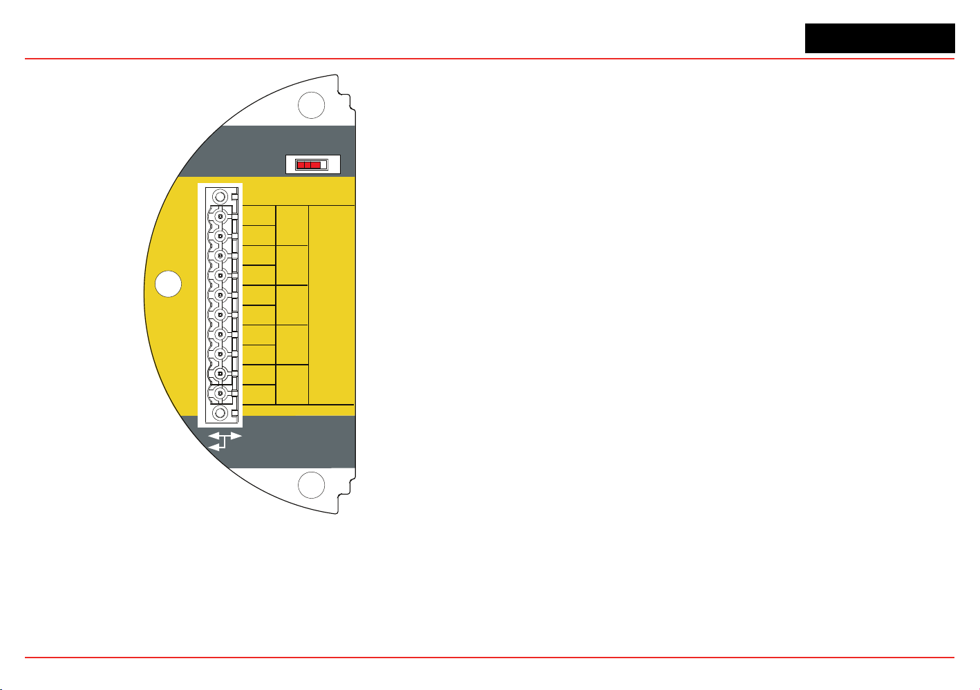
XNX Universal Transmitter
Appendix B - Modbus Protocol
184
Use shorting jumper
supplied to maintain
connection during
service
3-5
3-4
3-3
3-2
3-1
3-6
3-7
3-8
3-9
A
-
S5 EOL Term
-
+
+
A
B
B
S
TB-3
Modbus
In
Out
R =120Ω
T
3-10
S
Figure 248. Modbus connections
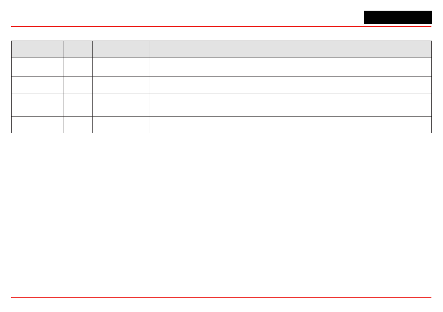
XNX Universal Transmitter
Appendix B - Modbus Protocol
185
B.2 Modbus Registers
Modbus Holding
Register Address
Datatype Variable Name Description
40001 Int16 ID MSB always 0x24 to facilitate automatic identication. LSB repeat of Modbus address.
40002 Int16 ID Identical to 40001
40003 to 40004 Float32 fCurrentConc
The reported gas concentration in current measurement units. For example, methane at 50% LEL would be reported as 50.0 here.
This concentration is forced to zero during inhibit mode.
40005 int16 iFaultWarnNumber
This is the integer representation of the fault status. If any fault exists this will take a value in the range 1000 to 1999. Otherwise,
if any warning exists, this will take a value in the range 1 to 999. Normally, this has the value zero. For example, if the XNX
temperature is out of range, this will take the value 1103.
40006 int8 iAlmFltLev
This register contains 4 meaningful bits regarding the presence of alarms or faults. The bit assignments are as follows: Bit 0:
AL1
active Bit 1: AL2 active Bit 4: Warning active Bit 6: Fault Active All others: For future expansion
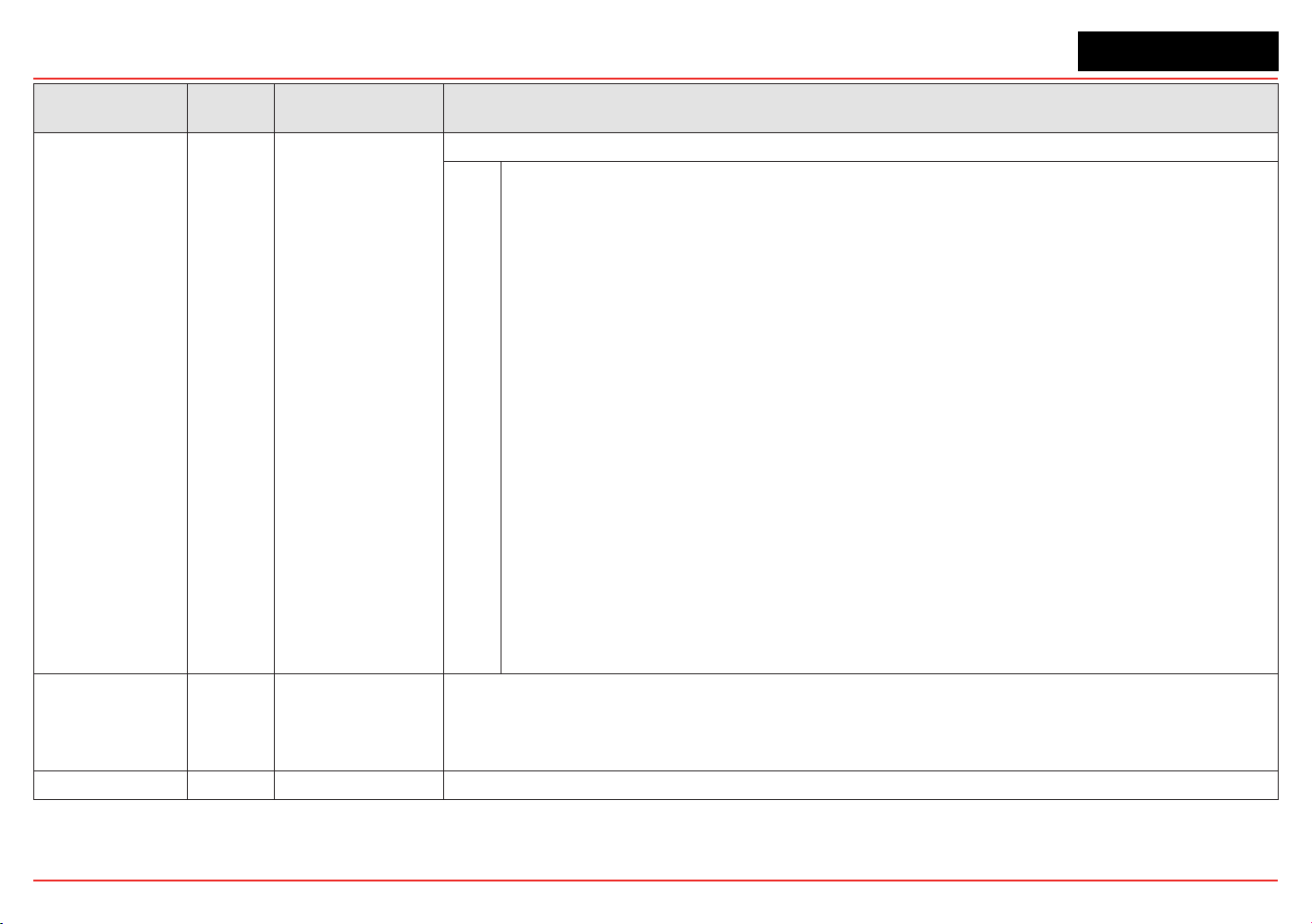
XNX Universal Transmitter
Appendix B - Modbus Protocol
186
Modbus Holding
Register Address
Datatype Variable Name Description
40007
uint8 iMonitoringState
This has the following meanings:
0
1
2
3
4
5
6
7
8
9
10
11
12
13
14
15
16
17
18
19
20
21-
255
reserved
normal monitoring
in warm-up
long-term inhibit
alarm simulation
fault simulation
Loop current stimulated
in warning MFlt
in Instrument Flt
in beam block
in bump test
short-term inhibit
performing zero calibration
performing span calibration
in pre-zero calibration
in pre-span calibration
in post-zero calibration, successful
in post-span calibration, successful
in post-zero calibration, failed
in post-span calibration, failed
in align Excel mode
for future expansion
40008 int16 iHeartBeat
This Heartbeat is provided to facilitate detection of communications problems in programming environments where the transport-
layer communication error information is unavailable. This increments approximately every 5 seconds.
It is the responsibility of the system integrator to notify plant personnel if a Modbus master fails to communicate with the XNX. This
register can facilitate this notication.
40009 to 40010 oat32 fSensorLifeDays This indicates the time remaining before the ECC sensor must be calibrated or replaced.
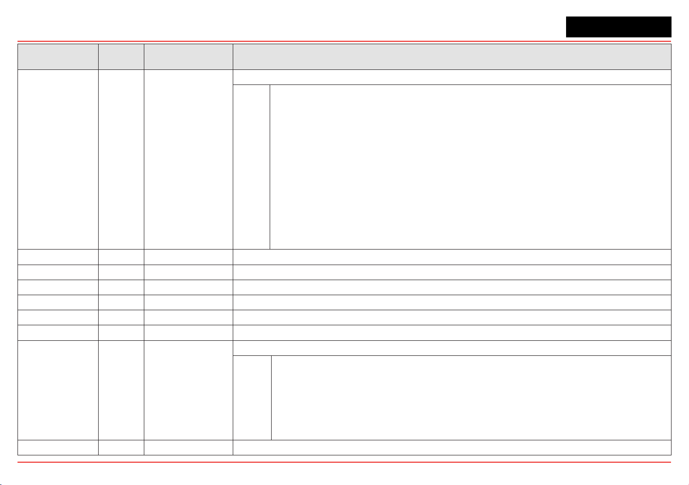
XNX Universal Transmitter
Appendix B - Modbus Protocol
187
Modbus Holding
Register Address
Datatype Variable Name Description
40011
int8 iMeasurementUnits
The meaning of this datum is as enumerated below:
0
1
2
3
4
5
6
7
8
9
10
11
12 to
255
Default
mg/m3
g/m3
%vol
ppm
%LEL
UEG
Ratio
%LEL*M
ppm*m
EG*m
%vol * meter
for future expansion
40012 to 40014 string[5] strGenericUnits User-dened 5 character string description for installed generic mA sensor
40015 int8 iWinTemp If a Searchline Excel is tted, this is the temperature of the window. Otherwise, this is the temperature of the window.
40016 int8 iTransTemp Temperature of the XNX in Celcius.
40017 int8 iSensorTemp Temperature of the sensor (Optima, Excel, ECC, etc)
40018 to 40026 string[18] strTransmitterID User-congured transmitter name.
40027 to 40035 string[18] sDateTime Format is “mm/dd/yy hh:mm:ss”. Month and day inverted if so congured.
40036
int8 iSensorType
The meaning of this datum is as enumerated below
1
2
3
4
5
7
Others
mV Bridge
Electrochemical Cell with toxic cartridge
Electrochemical Cell with O2 cartridge
Optima
Excel
generic mA input
for future expansion
40037 oat32 f_mA_Out The current produced by the XNX in milliamperes.

XNX Universal Transmitter
Appendix B - Modbus Protocol
188
Modbus Holding
Register Address
Datatype Variable Name Description
40038 int16 iTransVoltage24000 The voltage supplied to the XNX at the nominal 24.0 volt input, in millivolts.
40039 int16 iTransVoltage_3300 The voltage on a nominal 3.3 volt supply in the XNX, in millivolts.
40041 int16 iOptional3300 The voltage on a nominal 3.3 volt supply in the XNX option board, in millivolts.
40042 int16 iPersonality3300 The voltage on a nominal 3.3 volt supply in the XNX personality board, in millivolts.
40043 int16 iPersonality5000 The voltage on a nominal 5.0 volt supply in the XNX personality board, in millivolts.
40044 int16 iSensVoltage24000 The voltage supplied to an Optima or Excel sensor at the nominal 24.0 volt input, in millivolts.
40045 int16 iSensVoltage_5000 The voltage on a nominal 5.0 volt supply in Optima or Excel, in millivolts.
40046 to 40079 Contact HA for details.
40080 to 40081 int32 iTransSn Serial number of XNX.
40082 to 40083 int32 iSensSn Serial number of Optima, Excel, or ECC cartridge.
40084 int8 iSensSwVer Integer representation of software version in external sensor or mV personality module
40085 int8 iTransSwVer Software version of XNX.
40086 to 40155 Contact HA for details.

XNX Universal Transmitter
Appendix B - Modbus Protocol
189

XNX Universal Transmitter
XNX Universal Transmitter Technical Manual
191
Appendix C - Warranty
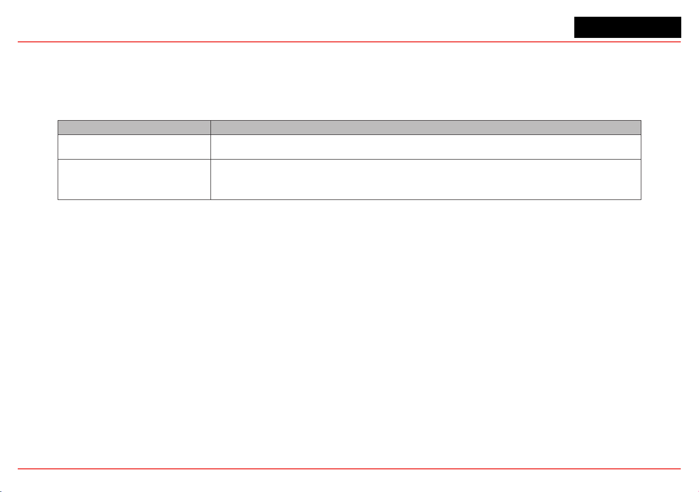
XNX Universal Transmitter
Appendix C - Warranty
191
Warranty Statement
All products are designed and manufactured to the latest internationally recognized standards by Honeywell Analytics under a Quality
Management System that is certied to ISO 9001.
The XNX
®
Universal Transmitter is warranted by Honeywell Analytics (herein referred to as ‘HA’) to be free from defects in material or
workmanship under normal use and service for:
Device Warranty Terms
XNX Universal Transmitter
(excludes consumables)
36 months from date of shipment to buyer
XNX Electrochemical Sensors
(Part Number XNX-XS****)
Multi-Purpose Detector (MPD)
12 months from date of commissioning by an approved Honeywell Analytics representative
or
18 months from date of shipment from Honeywell Analytics, whichever is sooner
Service in the eld or at the customer’s premises is not covered under these warranty terms. Time and travel expenses for on-site warranty
services will be charged at Honeywell Analytics’ normal billing rates. Contact your Honeywell Analytics Service Representative for information
on Service Contracts.
Warranty Conditions
1. The Honeywell Analytics (HA) Limited Product Warranty only extends to the
sale of new and unused products to the original buyer where purchased
from HA or from a HA authorized distributor, dealer or representative. Not
covered are: consumable items such as dry-cell batteries, lters and fuses
or routine replacement parts due to the normal wear and tear of the product;
any product which in HA’s opinion has been altered, neglected, misused or
damaged by accident or abnormal conditions of operation, handling, use or
severe sensor poisoning; defects attributable to improper installation, repair by
an unauthorized person or the use of unauthorized accessories/parts on the
product
2. Any claim under the HA Product Warranty must be made within the warranty
period and as soon as reasonably possible after a defect is discovered. If a
Warranty claim is being sought it is the responsibility of the buyer to obtain a
Service Event number (SE#) from HA and if practical return the product clearly
marked with the SE# and a full description of the fault.
3. HA, at its sole discretion, may elect to send replacement goods to buyer prior
to receipt of the defective goods. Buyer agrees to return defective goods with
in 30 days or to pay for the replacement goods.
4. Buyer is responsible for transportation costs from the buyer’s location to HA.
HA is responsible for transportation costs from HA’s location to the buyer.
5. If in the case of a xed installation or when it is not practical to return the
product, the buyer should submit a claim to HA Service Department. A service
engineer will attend on site on a day rate basis. Where a valid warranty claim
is identied, the faulty product will be repaired or replaced free of charge. A
warranty claim will be accepted if all conditions contained within this Warranty
are met.
6. When, in the opinion of HA, a warranty claim is valid, HA will repair or replace
the defective product free of charge and send it or any replacement back
to the buyer. If, in the opinion of HA the warranty claim is not valid, HA will,
at the option of the buyer, return the unit unaltered at the buyer’s expense,
repair the unit at the then prevailing rates, replace the unit with an appropriate
replacement item at the then prevailing price, or discard the unit. HA reserves
the right to charge for any attendance by its service engineer at the usual
rates in force at the time the claim was received.
7. In no event shall HA’s liability exceed the original purchase price paid by the
buyer for the product.
Consumer Claims
If you purchased your HA product as a consumer, the above warranty conditions do
not affect your rights under any applicable consumer protection legislation.
Honeywell Analytics reserves the right to change this policy at any time. Contact
Honeywell Analytics for current warranty information.

XNX Universal Transmitter
XNX Universal Transmitter Technical Manual
193
Index

XNX Universal Transmitter
Index
193
Symbols
4-20mA output 11, 37, 38
705, calibrating 94
705HT, calibrating 94
A
accessories 156
air speed, operating 132
alarm/fault simulation 81
alarm/fault status 83
alarms 67
alarm settings 83
approvals,
hazardous area 129
performance 129
B
battery life 128
baud rate 184
beam block options 72
bump test 22, 99, 100
C
cable
length 52
ports 128
recommended 132
cal gas range 134, 135,
133
Calibration 93–106
calibration
for MPD sensors 101
gas 90
gas ow adapter 15, 156
interval 71
span 90, 91
zero 90, 91
cal point 130, 131, 133
cartridges
catalytic bead replace-
ment 155
IR replacement 155
part numbers 130, 131,
133
Cautions 7
ceiling mount bracket kit
16, 156
cells, replacement 154
certications 11, 12
by part number series
145–147
chronological list, event,
by day 88
collecting cone 16, 157
Communications 11
conguration
displaying 22
verifying 79
congure menu 61
construction material 128
Control Drawings 159–166
remote sensor mount
165
controls 18
cover 12
cross-interferents 141
D
daisy-chain 32
date 22, 58, 81
dimensions 128
duct mount kit 16, 156
E
easy reset 78
EC. See
electrochemical
sensor
electrochemical sensor 40
cartridge, replacing with
different type 106
cartridge, replacing with
same type 105
cell 105
installation 40
operational life 98
enclosure
aluminum 12
stainless steel 12
event history 81, 87
F
eldbus
options 77
settings 83, 86
nish, marine 12
ow housing 97
force relays 80, 81
Foundation Fieldbus 54
functional gas test.
See
bump test
G
gas calibration 22, 90
gas data 83, 85
gases, selectable 61
gas name, changing 61
general status screen 19,
55
greases, airborne 141
H
H
2
S sensors, calibrating
94
HART
®
devices 52
handheld online menu
1751–179
interface 167–169
local 14
local handheld 51
output 11
protocol 51, 167–182
hex key 13
humidity 1284, 130, 131,
133
hydrogen sensors 142
I
information 7
information menu 83
inhibit 79
Installation and Operation
27–88
installation
daisy-chain 31, 32
maximum distance 31,
33
multiple transmitter 31
single transmitter 31
types of 31
intrinsic safety 5, 14
Introduction 9–26
IP rating 1284, 130
IS. See
intrinsic safety

XNX Universal Transmitter
Index
194
J
jumpers 38
jumper switch 54
L
language 22
selecting 57
latching 69
LCD. See
liquid crystal
display
LDL.
See
lower detection
limit
LED. See
light emitting
diode
light emitting diode 18,
20, 56
test 56
liquid crystal display 46,
56
lower detection limit 130,
131, 133
M
magnetic wand/screw-
driver 13, 17, 158
main menu 22
Maintenance 103–106
mA devices
generic, connecting 47
mA levels 70
mA
level settings 83, 86
output, calibrating 90,
100
output, forcing 80
sensor type 60
menu map 23
menu structure 20
messages
fault 113–119
informational 123–124
warning 1084–1117
Modbus
®
15, 54
interface card 184
protocol 183–188
registers 186–189
mounting kit, EC sensor
remote 41
mounting the enclosure
128
MPD. See
multi-purpose
detector
multi-purpose detector
155
ammable sensor 98
interface adapter 156
performance 142
sensor cartridge 104
multidrop mode 52
mV
personality wiring 43
remote sensor 45
N
navigation 18
non-latching. See
latching
notes 7
numeric format, selecting
69
O
off-scale readings 5
operating voltage 128
option board 38, 54
ordering information 152
organic vapors 141
O-ring, front cover 158
P
part numbers 83
parts list 13
passcode screens 79
personality board 36, 38
IR 48
mV 42, 44
personality, options, and
display (POD) 14, 36
personality wiring
electrochemical 39
IR 46, 48
pipe mount kit 15, 154
POD. See
personality, op-
tions, and display
point-to-point mode 51
power consumption 128
pressure
barometric 130, 131, 134
operating 132
product description 10, 12
R
range 67, 130, 131, 133
range/alarm settings 83,
85
real time clock 128
Reex cell fault diagnosis
10
relay
data 86
options 14, 53
settings 83
remote
sensor mounting kit 16,
156
gassing kit 16, 157
MPD mounting 157
response time 130, 131,
133
S
Safety 5–8
screwdriver 158
Searchline Excel 50, 56,
96
connecting 46
Searchpoint Optima Plus
50
connecting 46
security access level 59
security, conguring 78
Sensepoint HT, calibrat-
ing 94
sensors 14–26
cross-sensitivity 135–141
data 83, 85
location 28
mounting 28
performance 133
replacement 153
status 83, 85
types 59, 72
serial number 83
settings, displaying 22
shorting jumpers 157
signal 128
silicone compounds 141
simulation switch 38, 54
soft reset 101, 102
solvents 141
spares 156
Specications 127-158
stopping plugs 12, 158
switch conguration 37
system conditioning 142

XNX Universal Transmitter
Index
195
T
temperature 128, 130
ranges, extended 134
range, standard 134
terminal blocks 38, 54
connections 38
jumpers 157
pluggable 158
termination 128
test menu 79
time 22, 58, 83
transmitter
conguring 57
data 83, 84
information, displaying
21
status 83, 83
testing 22
U
units name, changing 61
units, setting 70
user interface 128
W
warm-up time 132
Warnings 5
Warnings and Faults
107–126
warranty 191–192
weatherproof cap 16, 157
weather protector 17, 157
weight 128
wiring 30
isolated 37
X
XNX front panel 17
Z
zero calibration 184


Find out more
www.honeywellanalytics.com
Americas
Honeywell Analytics
405 Barclay Boulevard
Lincolnshire, IL 60069
Tel: +1 847 955 8200
Toll free: +1 800 538 0363
Fax: +1 847 955 8208
Europe, Middle East, and Africa
Life Safety Distribution AG
Javastrasse 2
8604 Hegnau
Switzerland
Tel: +41 (0)1 943 4300
Fax: +41 (0)1 943 4398
Tel: +41 (0)1 943 4300
Fax: +41 (0)1 943 4398
Technical Services
www.honeywell.com
#508, Kolon Science Valley (l)
187-10 Guro-Dong, Guro-Gu
Seoul, 152-050
Korea
Tel: +82 (0)2 6909 0307
Fax: +82 (0)2 2025 0328
1998M0738 Revision 12
June 2015
© 2015 Honeywell Analytics
Please Note:
While every effort has been made to ensure
accuracy in this publication, no responsibility can
be accepted for errors or omissions.
Data may change, as well as legislation, and
you are strongly advised to obtain copies of the
most recently issued regulations, standards and
guidelines.
This publication is not intended to form the basis
of a contract.