Loading ...
Loading ...
Loading ...
XNX Universal Transmitter
Appendix A - HART
®
Protocol
168
or at any point along the 20 mA loop. Additionally, the optional local
HART interface (P/N: XNX-HIF) permits temporary connection of a
HART terminal to the transmitter. This local HART port is transformer-
coupled to the main 20 mA output. This port is intrinsically safe and
polarity insensitive. See Section 2.3.1 for more information.
The internal HART modem functions as a high-impedance current
source. Thus transferring the HART signal requires a certain minimum
loop resistance between the slave and a low-impedance power
supply.
Normally, this resistance is supplied by the control system and so
need not be explicitly added. However, special treatment is needed
when the 20 mA output is not used and the local HART interface is
needed. (An installer might choose to communicate using relays,
Modbus
®
, or Foundation
TM
Fieldbus instead.) In this case, the
supplied 510 ohm resistor must be tted to create an “articial” 20
mA loop. The resistor should be connected between TB-1 terminal
1-3 and terminal 1-6. Additionally, S1 and S2 should be placed in
“source” conguration. This is shown schematically in Figure 237.
The digital HART interface provides all of the capabilities of the local
user interface. The XNX transmitter has been designed to use the
portable Emerson eld communicator with DevCom2000 software for
Microsoft Windows
®
and Emerson AMS Intelligent Device Manager.
Using HART, a service person can display information, test, calibrate,
and congure. A map of the HART menus is provided in Section
A.1.3.
ATEX Conditions for Safe Use of Intrinsically Safe
HART Handheld Devices
For installations in which both the Ci and li of the intrinsically safe
apparatus exceeds 1% of the Co and lo parameters of the associated
apparatus (excluding the cable), 50% of Co and lo parameters are
applicable and shall not be exceeded, i.e., the Ci of the device plus
the C of the cable must be less than or equal to 50% of the Co of
the associated apparatus, and the li of the device plus the l of the
cable must be less than or equal to 50% of the lo of the associated
apparatus.
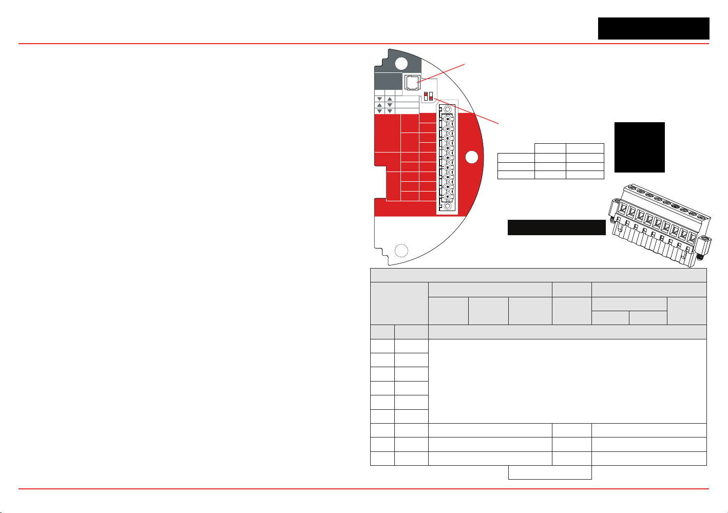
Figure 235. XNX mV Personality
Board Terminal Blocks, Jumper Switches
and Wire Color Chart
HART
20 mA
Operation
LOCAL
J1
S1
+V 1-1
mV TB-1
MPD, 705
Sensepoint
4-20mA
HART
16-32 VDC
6.5W max.
1-2
-V 1-3
1-4
+mA 1-5
-mA 1-6
Sense
1-7
0v 1-8
Ref 1-9
S1
Source
Sink
Isolated
S2
S2
XNX mV TB-1
▼▼
S2S1
▼▼
Isolated
▲
Sink
▼
Source
J1 - Local HART Option Connector
S1 and S2 - 20mA Output
Jumper Switch
▼
▲
mV Sensor Type
Catalytic Bead MPD w/IR
MPD
705
705HT
S’point
S’point HT
S’point
PPM
IR 5%
IR Flam
CO
2
CH
4
TB-1 Desc. Wire Color from Sensor
1 24v
See Section 2.2.4.
2
3 Gnd
4
5 20mA +
6 20mA -
7 Sense Brown Red Brown
8 0v White Green White
9 Ref Blue Blue Blue
Internal Ground
1
2
3
4
5
6
7
8
9
510 Ohm Resistor
Loading ...
Loading ...
Loading ...