Loading ...
Loading ...
Loading ...
XNX Universal Transmitter
Section 2 - Installation and Operation
37
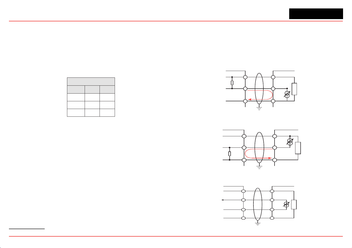
2.2.4
4-20mA Output, Common Connections, and
Power Settings
TheXNXUniversalTransmitterallowstheusertocongure
the 4-20mA output to Sink, Source, or Isolated mode
operation via two programming switches on the POD
1
. The
SwitchCongurationtableshowstheS1andS2settingand
correspondingoutputconguration.
Switch Conguration
Mode S1 S2
Source Down Up
Sink Up Down
Isolated Down Down
Mostcontrollersinthemarketwillacceptsource-congured
devices.Sink-conguredsignalsareusedinoldertechnology
controllers, which reduce the need for complete system
upgrades.In isolated-signal devices, if the controller fails or the
mAsignalwiresaredisconnectedorbroken,theelddevicewill
remain operational. Most controllers in the market will accept
isolatedcongureddevices.
Power and 4-20mA connections are made at TB-1 and are
identical for the EC, IR, and mV Personality Boards. For user
convenience, a second set of +Ve and -Ve power terminals have
been provided to eliminate the need for a secondary junction
box in multi-node systems when used with the supplied terminal
jumpers.
The total load resistance for the 4-20mA output should be
kept lower than 500Ω, including the resistance of the properly
selected 4-20mA cable and input impedance of the equipment
tobeconnnected.Theminimumloopimpedenceis200ohms;
1 The 4-20 mA output state is refreshed at least every two seconds (once per second is typical).
the maximum is 500 ohms. If the 20 mA output is not used, a 500
ohm resistor must be installed.
The XNX Universal Transmitter power consumption is dependent
onthesensorandoptionsforthespecicconguration.For
proper operation, the input voltage must be maintained at 16 to
32 VDC for EC and mV units and 18 to 32 VDC for IR units.
Controller
+VE
Signal
-VE
R
L
1
2
3
1-1
1-5
1-3
+V
+mA
-V
XNX
XNX Sink Configuration
Current
Flow
Figure 36. Sink wiring for XNX
XNX Source Configuration
Controller
+VE
Signal
-VE
R
L
1
2
3
1-1
1-6
1-3
+V
-mA
-V
XNX
Current
Flow
Terminate cable screen at the detector or controller, not both.
Figure 37. Source wiring for XNX
Controller
+V1
+V2
-V2
1-1
1-5
1-6
+V
+mA
-V
XNX
1-3
-mA
-V1
XNX Isolated Configuration
Figure 38. Isolated wiring for XNX
Loading ...
Loading ...
Loading ...